JP3850738B2 - Vacuum cleaner - Google Patents
Vacuum cleanerDownload PDFInfo
- Publication number
- JP3850738B2 JP3850738B2JP2002032474AJP2002032474AJP3850738B2JP 3850738 B2JP3850738 B2JP 3850738B2JP 2002032474 AJP2002032474 AJP 2002032474AJP 2002032474 AJP2002032474 AJP 2002032474AJP 3850738 B2JP3850738 B2JP 3850738B2
- Authority
- JP
- Japan
- Prior art keywords
- dust
- dust cup
- cyclone
- cleaning means
- cup
- Prior art date
- Legal status (The legal status is an assumption and is not a legal conclusion. Google has not performed a legal analysis and makes no representation as to the accuracy of the status listed.)
- Expired - Fee Related
Links
Images


Landscapes
- Filters For Electric Vacuum Cleaners (AREA)
Description
Translated fromJapanese【0001】
【発明の属する技術分野】
本発明は電気掃除機のサイクロン集塵装置に組み合わせられるフィルター清掃機構に関する。
【0002】
【従来の技術】
電動送風機により吸い込んだ吸気を旋回させて塵埃を分離するサイクロン集塵装置を備えた電気掃除機が広く使用されている。このようなサイクロン集塵式電気掃除機の例を図16に示す。
【0003】
図16の電気掃除機1は、電動送風機3を内蔵した本体2にサクションホース4及び接続パイプ5を介して吸込口体6を接続する。吸込口体6は床面fに面する吸込口7を有している。サクションホース4と接続パイプ5の間にはサイクロン集塵装置8が配置される。サイクロン集塵装置8の入口部は接続パイプ5に接続し、出口部はサクションホース4に接続しており、これにより、吸込口体6から接続パイプ5、サイクロン集塵装置8、サクションホース4を経て電動送風機3に至る吸気路が構成される。
【0004】
上記構成の電気掃除機1において、電動送風機3を駆動すると、吸気路に吸気流が発生し、吸込口体6の吸込口7から床面等の塵埃が吸い込まれる。気流は接続パイプ5を経てサイクロン集塵装置8に至り、ここで気流が高速旋回し、気流中の塵埃が遠心分離される。塵埃はダストカップ9に集積され、空気のみサクションホース4から電動送風機3に吸引され、本体2の外へと排出される。
【0005】
サイクロン集塵装置8の内部には、旋回気流の中心に位置するように排気筒が配置される。この排気筒には旋回する気流を排気する排気口が設けられ、ここに、ナイロン等の合成繊維を織って細かいメッシュを形成したフィルターが装着されている。このフィルターは、遠心力では気流から分離できなかった細かい塵埃を捕捉するためのものである。長時間の使用によりフィルターが目詰まりすると吸込気流の流量が減少し、吸塵能力が低下するので、このフィルターは適宜清掃し、目詰まりを解消しなければならない。本出願人は、サイクロン集塵装置の排気筒フィルター清掃機構に関し、これまでに次のような提案を行ってきた。
【0006】
第一に、特願2000−88500号記載のフィルター清掃機構がある。これは、着脱自在な排気筒に対しその側面を清掃する清掃手段を設け、この清掃手段を可動部材で作動させるようにしたものである。排気筒を取り出してフィルターへの塵埃付着状況を目で確認しつつ清掃できるため、フィルターの目詰まりを確実に解消できるものであるが、排気筒と可動部材を手で持って作業を行うため、手が汚れる上、周囲に塵埃が飛散するという難点があった。
【0007】
第二に、特願2000−238691号記載のフィルター清掃機構がある。これは、着脱自在な集塵室の開口部に清掃具を設け、吸気路に固定した排気筒に対し集塵室を移動させるか、あるいは集塵室に取り付けた排気筒を集塵室から引き抜くとき、清掃具がフィルターを摺擦するようにしたものである。フィルターから掻き落とされた塵埃は集塵室で受けられ、周囲に飛散することはないが、集塵室内の塵埃を捨てるとき、一々清掃具を取り外さねばならないという不便さがある。
【0008】
第三に、特願2000−241333号記載のフィルター清掃機構がある。
これは排気筒に設けた清掃具を様々な動力源で駆動するようにしたものであり、図17、18を用いてその機構の一例を紹介する。
【0009】
図17はサイクロン集塵装置8の構造を示す縦断面図であり、接続パイプ5の長手方向を垂直にした場合を示している。10はサイクロン集塵装置8のサイクロン本体である。サイクロン本体10は連結管11の部分と塵埃分離室12の部分からなり、接続パイプ5に連結する連結管11の上端をエルボ状に水平に曲げ、その先端に塵埃分離室12を一体形設した構成となっている。接続パイプ5の軸線と連結管11の軸線は同一直線上に並ぶ。
【0010】
塵埃分離室12はカップを伏せたような形状で、下端が開口部となっている。塵埃分離室12はほぼ円形の水平断面形状を有し、内周面の一部に連結管11の前記エルボ状部からの空気吹出口13を開口させている。空気吹出口13は、連結管11から塵埃分離室12の内周面に対し接線方向に気流が流入し、塵埃分離室12の内部に高速の旋回気流を形成するような位置と角度に設定されている。
【0011】
塵埃分離室12の中心付近、旋回気流の中心となる箇所には排気筒14を、その軸線がダストカップ9の軸線と平行になるようにして配置する。排気筒14は底面が閉じ、上面が開口した円筒形の部材であって、周壁には旋回する気流を塵埃分離室12から排気する複数個の排気口15が設けられている。排気口15の外周にはナイロン等の合成繊維を織って細かいメッシュを形成したフィルター16を装着する。フィルター16は排気筒14の外周にかぶせられる形で装着されており、このため排気口の縁は排気筒14の外側に露出しない。
【0012】
排気筒14の上面開口部は塵埃分離室12の天井面に形設された連結管17に挿入される。排気筒14は、その上部に形設した雄ネジ部14aを連結管17の内面の雌ネジ部に螺合することにより、塵埃分離室12の天井面から垂下する形で取り付けられるものである。連結管17の他端にはサクションホース4が接続する。
【0013】
サイクロン本体10にはダストカップ9が気密に連結する。ダストカップ9は下端が閉じ、上端が開口した円筒形の部品であり、上端開口部に向け緩やかなテーパで広がっている。ダストカップ9の上端開口部を塵埃分離室12の下端の開口部にあてがい、ダストカップ9の上端開口部が所定の嵌合しろ分だけ塵埃分離室12に差し込まれるようダストカップ9を押し上げると、塵埃分離室12の下端開口部がダストカップ9の外面に装着した環状のガスケット18に密着し、サイクロン本体10とダストカップ9との気密連結が成立する。この時、ダストカップ9の軸線方向は連結管11及び接続パイプ5の軸線方向と平行になる。すなわち、接続パイプ5の長手方向が垂直であればダストカップ9の軸線方向も垂直となる。排気筒14の軸線もこの時垂直になっており、ダストカップ9は排気筒14の軸線方向に摺動させて着脱することになる。
【0014】
排気筒14の下端には傘状の分離フード20が取り付けられている。分離フード20は、排気筒14の下端に螺合する雌ネジ部21を上端に有し、そこから斜め下へ円錐形に広がり、円錐形の広がりの先端から下に向けて円筒形の外輪22を垂設した形状になっている。外輪22とダストカップ9の間には環状の空間23が形成される。
【0015】
上記サイクロン集塵装置8に気流が吸い込まれると、気流は連結管11から空気吹出口13を通って塵埃分離室12の中に流れ込む。前述の通り、空気吹出口13は塵埃分離室12の内周壁に対し接線をなすような位置と角度に設けられており、このため塵埃分離室12に入った気流は塵埃分離室12の内周壁に沿って高速で旋回する。旋回するうちに気流中の塵埃は遠心力で塵埃分離室12の内周壁の方へ押しやられる。
【0016】
塵埃分離室12で発生した旋回気流は下降し、分離フード20の外側を通ってダストカップ9の中を下方に進む。気流が旋回を続けるうちに塵埃はますます遠心分離される。下降する旋回気流はダストカップ9の底面に近づくと上昇に転じる。
【0017】
ダストカップ9の底部に集積した塵埃が旋回気流によって再び舞い上がることを防ぐため、ダストカップ9の内周面には垂直方向に延びるリブ19が複数条形設される。リブ19はダストカップ9の底部より、ダストカップ9の高さの半分弱の高さまで延びる。旋回気流がリブ19に衝突すると気流は方向転換し、その際さらに塵埃が分離される。遠心力で、又はリブ19に衝突して気流から分離した塵埃はダストカップ9の底面の側壁に近い側に落ち、集積して行く。集積した塵埃は旋回気流に追従して旋回しようとするが、リブ19がその動きを抑制する。
【0018】
ダストカップ9の底面近くで上昇に転じた旋回気流は下降旋回気流の内側を通って上昇する。上昇旋回気流は分離フード20の縁を越して塵埃分離室12に帰還する。塵埃分離室12に帰還した旋回気流は次第に旋回半径を縮小しつつ排気筒14に接近し、最終的には排気筒14の内部に吸い込まれる。もし気流の中に塵埃が残留していたとしても、それはフィルター16により捕捉される。排気筒14の中へ抜けた気流はサクションホース4を経て電動送風機3に吸い込まれ、本体2の外へと排出される。
【0019】
連結管11の側面には、ダストカップ9の側面を受け止めるダストカップ保持部24が連結管11の軸線方向に沿う形で形設されている。ダストカップ保持部24の下部には、ダストカップ9の底部を支えるスライダ25を保持するスライダ保持部26が設けられる。スライダ25は連結管11の軸線方向に沿ってスライド可能である。スライダ25の正面にはダストカップ9の底面に設けた陥没部27に係合するブラケット28と、その上に少し間隔を明けて、水平な突片29が形設される。ダストカップ9の側面には、ブラケット28と突片29の間の隙間に差し込まれる水平な突片30と、それより少し上の箇所に、上向きフック31が形設される。スライダ保持部26にはこの上向きフック31を係合させる下向きフック32を形設する。
【0020】
スライダ25の裏面には凹部33が形設され、スライダ保持部26の内部にはこの凹部33に係合する凸部34を有するロック片35が配置される。ロック片35は下端を中心に垂直面内で回動可能であり、バネ36により、凸部34を凹部33に係合させる方向に付勢されている。
【0021】
ダストカップ9の陥没部27をブラケット28に係合させ、突片29とブラケット28の間に突片30を差し込んだ状態でダストカップ9を押し上げると、スライダ25も同時に引き上げられる。行程の最後で、すなわちダストカップ9の上端開口部が所定の嵌合しろ分だけ塵埃分離室12に差し込まれた時点で上向きフック31が下向きフック32に係合し、ダストカップ9の下部は水平方向に引いてもダストカップ保持部24から離れなくなる。この時丁度、ロック片35の凸部34がスライダ25の凹部33に係合し、スライダ25をロックする。このためスライダ25の降下は阻止され、ダストカップ9はサイクロン本体10に気密に連結した状態で保持される。
【0022】
ダストカップ9を取り外すときは、ロック片35に連結したロック解除ボタン(図示せず)を操作し、ロック片35をバネ36の付勢力に抗して押す。すると凸部34が凹部33から離脱する。図18のようにダストカップ9を押し下げるとスライダ25も共に下がり、上向きフック31と下向きフック32の係合が解除され、ダストカップ9をサイクロン本体10から分離することが可能になる。分離したダストカップ9は塵埃受け容器のところまで運び、内部に堆積した塵埃を捨てる。
【0023】
排気筒14はその外側に清掃手段40を保持する。清掃手段40はリング41の内側にブラシ42を設けたものである。リング41は塵埃分離室12の内寸法より僅かに小さい外寸法を有し、塵埃分離室12の内部をスムーズに動くことができる。ブラシ42は合成繊維製の剛毛を、その毛先がリング41の中心に向くよう植え込んだものである。ブラシ42の毛先は排気筒14の外面曲率に見合う曲率に揃えられていて、フィルター16に弾力的に接触する。
【0024】
排気筒14の外側に清掃手段40をかぶせた後、排気筒14に分離フード20を螺合すると、清掃手段40は排気筒14から脱落しなくなる。清掃手段40は排気筒14の外側を一定のストローク範囲内で、すなわち排気筒14の上部外面に形設したフランジ43を上限とし、分離フード20を下限とするストローク範囲内で、排気筒14の軸線方向に摺動可能である。塵埃分離室12の天井とリング41との間に挿入したバネ44が清掃手段40を排気筒14の先端方向に向けて付勢する。塵埃分離室12の下端開口部に挿入されたダストカップ9の上縁がリング41の下面に当たるので、ダストカップ9を押し上げると清掃手段40もバネ44に抗して押し上げられることになる。ダストカップ9が限界までサイクロン本体10に押し込まれると、清掃手段40は図17に示す高さに保持される。
【0025】
清掃手段40を持ち上げるため、ダストカップ9の嵌合しろは深く設定されており、そのためダストカップ9の上部が空気吹出口13を覆ってしまう。この問題を解決するため、ダストカップ9には、空気吹出口13をダストカップ9内に連通させる、空気吹出口13と同じ大きさの開口45が形設されている。陥没部27とブラケット28の係合により、ダストカップ9のサイクロン本体10に対する水平面内の取付角度は一定となるので、開口45と空気吹出口13の角度関係も一定であり、ダストカップ9をサイクロン本体10に嵌合しろ一杯まで差し込めば、空気吹出口13と開口45とはぴったり一致する。
【0026】
塵埃廃棄のため、ロック片35とスライダ25の係合を外し、図18のようにダストカップ9を降下させると、清掃手段40がバネ44によって押し下げられる。この時ブラシ42がフィルター16に接触しながら摺動し、フィルター16に付着していた塵埃をかき落とす。前述の通り、フィルター16が排気筒14の外側に被着され、排気口15の縁が排気筒14の外側に露出しないので、ブラシ42が排気口15の縁に引っかかることもなく、清掃手段40はスムーズに移動する。かき落とされた塵埃はダストカップ9に受け止められる。かき落とし動作は清掃手段40が分離フード20に当たって止まるまで続くが、その間中排気筒14はダストカップ9に包囲されており、ダストカップ9の外に塵埃が飛散することはない。
【0027】
フィルター16からダストカップ9に落ちた塵埃は、前からダストカップ9の内部に堆積していたゴミと一緒に捨てられる。ダストカップ9をダストカップ保持部24から外した後も、清掃手段40は排気筒14に保持され、サイクロン本体10の側に残る。ゴミ捨て後、ダストカップ9を再度サイクロン本体10に取り付けると、ダストカップ9が清掃手段40を押し上げる過程でブラシ42がフィルター16を今度は下から上へとこすって清掃する。ダストカップ9がリング41に密着し、排気筒14はダストカップ9に包囲されているので、フィルター16を離れた塵埃がダストカップ9の外に飛散することはない。このように、ダストカップ9を着脱する度にフィルター16の清掃が行われる。
【0028】
上記の通り、図17、18に記載した構成によれば、ダストカップを着脱する度にフィルターの清掃が行われる。しかしながらフィルターにびっしりと付着した塵埃を除去したり、摺動面の損傷や塵埃付着で動きが重くなった清掃手段を確実に動かすためには、清掃手段を付勢するバネを強力なものとしなければならず、ダストカップをサイクロン本体に差し込むのに大きな力を要することになる。と同時に、折角強力なバネを配置していても、摺動抵抗がそれ以上であれば結局は清掃手段が停止してしまい、フィルターを清掃することができないという問題があった。
【0029】
【発明が解決しようとする課題】
本発明は上記の点に鑑みなされたものであって、ダストカップの着脱毎にサイクロン集塵装置のフィルター清掃が確実に遂行される構成とすることを目的とする。
【0030】
【課題を解決するための手段】
本発明電気掃除機は次の構成を備える。
【0031】
(1)電動送風機の運転によって発生する気流により床面等の塵埃を吸込口から吸い込み、前記吸込口と連通する吸気路を介して吸い込んだ気流を旋回させて気流を塵埃と分離するサイクロン集塵装置を備え、このサイクロン集塵装置は、前記吸込口から吸い込んだ気流を旋回させる塵埃分離室を形成するサイクロン本体と、このサイクロン本体に着脱可能に連結し、気流から分離した塵埃を集積するダストカップと、このサイクロン本体に取り付けられ、前記塵埃分離室内の旋回気流の中心に位置し、旋回する気流を塵埃分離室から排気する排気口にフィルターを装着した排気筒とを有する電気掃除機において、前記フィルターは前記排気筒の外周にかぶせられる形で装着されるものであり、このフィルターの外側に清掃手段を設け、前記清掃手段は、前記フィルターに接触するブラシを内側に有するリングからなり、前記排気筒先端方向にバネで付勢されるとともに、前記ダストカップに分離可能に連結する連結手段を備え、前記ダストカップを前記サイクロン本体に着脱するときのダストカップのスライドに従って前記排気筒の外側を摺動するものであり、前記ダストカップを前記サイクロン本体から取り外したときにはサイクロン本体又は前記排気筒に保持されることとした。
【0032】
この構成によれば、ダストカップをサイクロン本体に着脱するときのダストカップのスライドに従って排気筒の外側で清掃手段を摺動させるものであるから、塵埃を捨てる都度確実にフィルターを清掃し、フィルターの目づまりを解消することができる。フィルターから落下する塵埃はその場でダストカップに受け止められ、周囲に飛散することがない。
【0033】
またサイクロン本体から外れるのはダストカップのみであり、清掃手段はサイクロン本体又は排気筒に保持されて後に残るので、清掃手段に一切手を触れる必要がなく、手の汚れを気にしなくて済む。
【0034】
また清掃手段を排気筒先端方向にバネで付勢したから、排気筒先端方向への清掃手段の摺動がアシストされ、フィルター清掃作業が楽になるとともに、ダストカップ自身のサイクロン本体からの分離も容易になる。
【0035】
(2)電動送風機の運転によって発生する気流により床面等の塵埃を吸込口から吸い込み、前記吸込口と連通する吸気路を介して吸い込んだ気流を旋回させて気流を塵埃と分離するサイクロン集塵装置を備え、このサイクロン集塵装置は、前記吸込口から吸い込んだ気流を旋回させる塵埃分離室を形成するサイクロン本体と、このサイクロン本体に着脱可能に連結し、気流から分離した塵埃を集積するダストカップと、このサイクロン本体に取り付けられ、前記塵埃分離室内の旋回気流の中心に位置し、旋回する気流を塵埃分離室から排気する排気口にフィルターを装着した排気筒とを有する電気掃除機において、前記フィルターは前記排気筒の外周にかぶせられる形で装着されるものであり、このフィルターの外側に清掃手段を設け、前記清掃手段は、前記フィルターに接触するブラシを内側に有するリングからなり、前記ダストカップは前記サイクロン本体から前記排気筒の軸線方向に摺動させて取り外すものとし、前記ダストカップには前記清掃手段から垂下するロッドに係合して清掃手段を一体的に移動可能に連結する係合部を設け、前記ダストカップを前記サイクロン本体から取り外したときには前記ロッドから前記係合部が外れ、前記ロッドは前記サイクロン本体又は前記排気筒に保持されることとした。
【0036】
この構成によれば、ダストカップと清掃手段とがロッドと係合部によって連結され、ダストカップを着脱するときに両者一体となって排気筒の軸線方向に移動するため、ダストカップを介して清掃手段を人力で力強く動かすことができ、フィルターから塵埃を確実に除去することができる。摺動抵抗大なるが故に清掃手段が動かないといったこともない。ダストカップを分離した後、ロッドはサイクロン本体又は排気筒に保持されて残るので、ダストカップを身軽にして塵埃受け容器のところまで運ぶことができ、ダストカップの取り扱いが容易になる。
【0037】
(3)上記構成の電気掃除機において、前記ダストカップは前記サイクロン本体に対し所定の位置関係をなしたとき、サイクロン本体に着脱可能となるものであり、この位置関係において前記係合部が前記ロッドに連結することとした。
【0038】
この構成によれば、ダストカップをサイクロン本体から取り外すためにはダストカップをサイクロン本体に対し所定の位置関係に置く必要があり、そこまで移動し、又はそこから移動するときにロッドを介してダストカップに連結した清掃手段によるフィルター清掃が確実に実行される。
【0039】
(4)上記構成の電気掃除機において、前記ロッドに係合して前記清掃手段の摺動を拘束するロック部材を設けた。
【0040】
この構成によれば、ダストカップをサイクロン本体から取り外したときのままの位置に清掃手段を維持しておくことができる。
【0041】
(5)上記構成の電気掃除機において、前記ロッドに係合して清掃手段の摺動を拘束するロック部材を設けるとともに、このロック部材は、前記ダストカップとサイクロン本体とが前記所定の位置関係をなし且つダストカップがサイクロン本体から取り外されたとき、自動的に拘束態勢に入るものとした。
【0042】
この構成によれば、ダストカップをサイクロン本体から取り外すだけで、ダストカップをサイクロン本体から取り外したときのままの位置に清掃手段が拘束される。
【0043】
(6)上記構成の電気掃除機において、前記ロック部材は、前記ダストカップが前記サイクロン本体から取り外されている間中前記拘束を続け、前記ダストカップが前記サイクロン本体に取り付けられる態勢に入ったとき、前記拘束を解除するものとした。
【0044】
この構成によれば、ダストカップをサイクロン本体から取り外すだけで清掃手段が拘束され、またダストカップをサイクロン本体に取り付ければそれだけで清掃手段の拘束が解除され、同時にダストカップと清掃手段の連結が復活する。
【0045】
前記塵埃分離室の一部に、前記清掃手段を前記旋回する気流から退避させておくための清掃手段受入部を設けてもよい。
【0046】
この構成によれば、清掃手段を旋回気流から退避させておけるので、旋回気流に含まれる塵埃が清掃手段に付着し堆積すること、また清掃手段が気流旋回の妨げとなることを防止できる。
【0047】
前記ダストカップを、バヨネット結合を用いて前記サイクロン本体に連結することとしてもよい。
【0048】
この構成によれば、ダストカップを簡単な操作でサイクロン本体に着脱できる。
【0049】
【発明の実施の形態】
以下、本発明電気掃除機の第1実施形態を図1〜図5に基づき説明する。第1実施形態はサイクロン集塵装置の部分を除くほか図16〜図18で紹介した従来構造例と構造が同じなので、従来構造例と共通する構成要素については前に使用した符号をそのまま付し、説明は省略するものとする。同じ原則を第2実施形態以降の実施形態の説明にも適用し、既述の構成要素には前と同じ符号を付し、支障のないかぎり説明を省略する。
【0050】
第1実施形態においては、ダストカップ9に図17のダストカップ9にあったような陥没部27が形設されていない。その代わり、背面側の側面に係合凹部51が形設されている。
【0051】
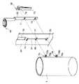
サイクロン本体10においては、ダストカップ保持部24からスライダ保持部26と、これに保持されていたスライダ25、及びロック片35が削除された。これに代えダストカップ保持部24の正面側(ダストカップ9に面する側)に、連結管11の軸線方向と平行する溝52を形設した。溝52は、清掃手段40のリング41から垂下する板状のロッド53を上下スライド自在に受け入れる。ロッド53の下端にはダストカップ9側の係合部である係合凹部51に係合する、ロッド53側の係合部である係合凸部54が形設されている。ロッド53と係合凸部54が、ダストカップ9に分離可能に連結する連結手段50を構成する。連結手段50は溝52に受け入れられる形でサイクロン本体10に保持される。図4に示すように係合凸部54は直方体形状であり、これを受け入れる係合凹部51も直方体形状になっている。なおリング41とロッド53は一体成形してもよいし、別々に成形したものを組み合わせてもよい。
【0052】
図3及び図4に示すように、ロッド53の片側の側面には垂直方向に間隔を置いて2個のノッチ55、56が形設される。ダストカップ保持部24に設けたロック手段60がノッチ55、56の一方に係合し、清掃手段40の摺動を拘束する。ロック手段60は、ダストカップ保持部24から水平に突出する支軸61と、ロック部材であるところの、垂直面内で回動できるよう支軸61に取り付けたロックレバー62と、ロックレバー62に図3において反時計方向の回転付勢力を与えるバネ63とからなる。ロックレバー62は一方の端がノッチ55、56に係合する係合部64、他方の端はダストカップ保持部24に設けた窓65から外部に突出する操作部66となっている。
【0053】
なおノッチ55、56の形状に関して言えば、ノッチ56は正面形状が矩形で上下の縁とも水平であるが、ノッチ55は上縁こそ水平であるが下縁は外側に向かって下がって行く斜面57となっている。そのため、ノッチ55からロックレバー62を外すのは単にロッド53を上方に押し上げるだけで良い。ノッチ55がロックレバー62に対し相対的に上方に移動することにより、係合部64が斜面57を滑り、ひとりでにノッチ55から抜け出す。
【0054】
ダストカップ9はガスケットを保持せず、サイクロン本体10の塵埃分離室12の下端開口部の内側に、オーリング形式のガスケット18が取り付けられている。ガスケット18はダストカップ9の外面に密着して気密を保つ。従来構造例と同様、ダストカップ9側にガスケットを装着することとしても構わない。
【0055】
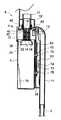
第1実施形態におけるフィルター16の清掃について説明する。図1はダストカップ9を使用状態にセッティングした状況を示す。ダストカップ9の上端開口部は塵埃分離室12の下端開口部の中に嵌合しろ一杯まで差し込まれている。上向きフック31は下向きフック32に係合している。連結手段50は連結状態にあり、清掃手段40はロッド53により、バネ44に抗する形で上方に持ち上げられている。この時ロッド53の下方のノッチ56にロックレバー62の係合部64が係合し、ロッド53の下方への動きを止めるので、ロッド53は上にも下にもスライドできない。従って清掃手段40は排気筒14の軸線方向の摺動を拘束される。清掃手段40が拘束されると同時に、連結手段50で連結したダストカップ9も下方への移動を拘束され、サイクロン本体10から抜け出すことはない。
【0056】
図1の状態で電動送風機3の駆動が行われると、サイクロン集塵装置8に気流が吸い込まれる。気流は連結管11から空気吹出口13を通って塵埃分離室12の中に流入し、排気筒14の周囲に高速の旋回気流を形成する。高速旋回に伴う遠心力により、気流に含まれていた塵埃は気流から分離され、ダストカップ9の中に落下し集積されて行く。
【0057】
ダストカップ9の中の塵埃を捨てるときは、電動送風機3を停止させた上で、ロックレバー62の操作部66を押して係合部64をノッチ56から外し、ダストカップ9を下方へ引き抜く。ダストカップ保持部24に沿って、すなわち自己の軸線に沿ってダストカップ9が下方にスライドする(図1の矢印Z2方向)に従い、ロッド53に引かれて清掃手段40が、ダストカップ9と軸線同士を平行にする排気筒14の外側を下方に摺動する。バネ44がこの摺動をアシストする。
【0058】
清掃手段40が摺動するにつれ、ブラシ42がフィルター16をこすり、フィルター16の外面に付着していた塵埃をこそぎ落とす。フィルター16が排気筒14の外周に装着され、排気口15の縁が排気筒14の外側に露出していないので、ブラシ42が排気口15の縁に引っかかることがなく、清掃手段40はスムーズに摺動する。フィルター16から離れた塵埃は分離フード20とダストカップ9の間の空間23を通ってダストカップ9の中に落下する。なおロックレバー62の操作部66を押す必要があるのはロッド53が下方へのスライドを始めるまでで、後は指を離しても良い。ロックレバー62の係合部64が側面に当たった状態でロッド53はスライドする。
【0059】
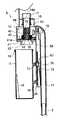
図5のようにブラシ42が分離フード20の上端に達したところで清掃手段40の摺動は終了する。この時ロックレバー62の係合部64もロッド53のノッチ55に係合しており、ダストカップ9を下に引いても清掃手段40をそれ以上摺動させることはできない。すなわち清掃手段40は排気筒14の軸線方向の摺動を拘束された形である。この状態になったらダストカップ9をダストカップ保持部24から引き離す。ロッド53の係合凸部54はダストカップ9の係合凹部51から抜け、連結手段50はダストカップ9との連結を解除した状態になる。このようにしてサイクロン本体10から取り外したダストカップ9を塵埃受け容器のところまで運び、塵埃を捨てる。ダストカップ9を取り外したとき、清掃手段40は排気筒14に保持され、連結手段50はサイクロン本体10に保持されて、それぞれ後に残る。
【0060】
塵埃を捨てた後、ダストカップ9をダストカップ保持部24にあてがい、ダストカップ9をサイクロン本体10に連結する体勢に置くと、ロッド53の係合凸部54がダストカップ9の係合凹部51に係合する。すなわち分離していた連結手段50が再びダストカップ9に連結する。連結が確実に行われるよう、図示しないが、ダストカップ9をあてがう際の目印となる標識がダストカップ保持部24に設けられている。
【0061】
連結手段50が連結状態となった後、ロックレバー62の操作部66を押して係合部64をノッチ55から外し、ダストカップ保持部24に沿ってダストカップ9を押し上げる。ダストカップ9が上昇する(図1の矢印Z1方向)に伴い、清掃手段40も排気筒14の外側を上方に摺動し、ブラシ42がフィルター16の外面を清掃する。なおロックレバー62の操作部66を押して係合部64をノッチ55から外さなくても、ダストカップ9を上方に強く押せば、ロックレバー62の係合部64はノッチ55の斜面57を滑ってノッチ55から抜け出す。従ってダストカップ9を強い力で押し上げるだけでロック手段60による清掃手段40の拘束は解除される。
【0062】
ダストカップ9の上部がガスケット18に嵌合した後、ダストカップ9をさらに押し込むと、上向きフック31が下向きフック32に完全に係合する。これが上方への摺動の限界である。この時ロックレバー62の係合部64がロッド53のノッチ56に係合し、ロッド53の下方へのスライドを阻止する。従って清掃手段40及びダストカップ9はこの位置で拘束され、塵埃吸い込み再開の準備が整ったことになる。
【0063】
上記実施形態では、清掃手段40の摺動をロック手段60で拘束し、これによりダストカップ9も拘束されることとしたが、ダストカップ9に対しロック手段(クランプ手段と言い換えてもよい)を設け、清掃手段40に対してはロック手段を設けない構成とすることもできる。清掃手段40にロック手段がないと、連結手段50を再連結する際、係合凸部54と係合凹部51をうまく位置合わせできるかどうかが問題になるが、清掃手段40がバネにより排気筒14の先端方向に付勢され、ダストカップ9を分離した後も自律的に位置を保っているのであれば、特に問題はない。
【0064】
上記実施形態にさらに改変を加えることも可能である。例えば、フィルター16を清掃するのがブラシである必要はない。ゴムあるいは合成樹脂からなる弾性片や、起毛した布をブラシの代わりに用いることができる。また清掃手段と連結手段の保持については、清掃手段が排気筒に保持され、連結手段がサイクロン本体に保持されるということを必須とするものではない。清掃手段が排気筒ではなくサイクロン本体に案内されて摺動するようにしてもよいし、連結手段が排気筒に案内されて摺動するようにしてもよい。要はダストカップをサイクロン本体から取り外したとき、清掃手段と連結手段がサイクロン本体又は排気筒のどちらかに保持されて後に残るようになっていればよい。
【0065】
本発明電気掃除機の第2実施形態を図6に示す。第2実施形態は第1実施形態の構成に改良を加えたものである。第1実施形態の構成では、ダストカップ9を引き下げてダストカップ保持部24から引き離した後、ロッド53に上向きの強い力がかかると、ロックレバー62の係合部64がノッチ55の斜面57を滑ってノッチ55から抜け出すことが考えられる。清掃手段40が上限まで上昇してロックレバー62の係合部64がノッチ56に係合したりすると、たとえバネ44を設けていたとしても清掃手段40は下降しない。すなわちロッド53の係合凸部54が、ダストカップ9の係合凹部51を待ち受けるべき位置から消えてしまうことになる。
【0066】
上記の問題に対処するため、第2実施形態では次のようにした。すなわち溝52の深さを、上の方では第1実施形態と同じにするが、塵埃分離室12の途中あたりから第1実施形態以上に深く掘り下げ、ロッド53が連結管11の方へ撓み得るようにする。他方ダストカップ9においては、係合凹部51の上方の口縁を面取りし、斜面58としている。
【0067】
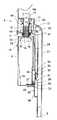
上記構成においては、ダストカップ9が取り外された後、清掃手段40が図6のように上限まで押し上げられ、ロックレバー62により保持されていた場合、ダストカップ9をダストカップ保持部24にあてがって押し上げて行くと、斜面58がロッド53の係合凸部54に当たる。斜面58は係合凸部54を図の右方に押しやり、ロッド53は図のように撓んでダストカップ9の上昇を許す。上向きフック31が下向きフック32に係合するところまでダストカップ9を押し上げると係合凸部54が係合凹部51に係合し、ダストカップ9はこの位置で拘束される。ダストカップ9とロッド53との係合がスムーズに進行するよう、ロッド53は撓みやすい合成樹脂あるいはバネ鋼で成形しておく。
【0068】
なお第2実施形態では、塵埃分離室12の上端に清掃手段受入部59が設けられている。清掃手段受入部59は空気吹出口13よりも上のレベルにあり、清掃手段40のリング41の平面形状と相似の水平断面を備える。清掃手段40が上限まで押し上げられたとき、清掃手段40は清掃手段受入部59にすっぽりとはまり込み、空気吹出口13より吹き出す旋回気流から退避する。ブラシ42もリング41より上のレベルに設けられており、そのため清掃手段40が気流旋回の妨げにならない。また旋回気流に含まれる塵埃が清掃手段40に付着して堆積することもない。
【0069】
図7〜図14に本発明電気掃除機の第3実施形態を示す。第3実施形態はロック手段60に改良を加えた点を特徴とする。すなわち第1実施形態のロック手段60は、清掃手段40の拘束を解くのにロックレバー62の操作部66を押す必要がある。ロックレバー62の係合部64が係合するノッチに斜面を設けておくことにより、ダストカップ9に強い力を加えれば自動的にロック解除となるようにすることが可能ではあるが、使用者が女性や子供である場合、そのような力を発揮することが無理なことも多い。
【0070】
そこで、ダストカップ9がサイクロン本体10から取り外されるとロック手段60は自動的に清掃手段40を拘束する態勢に入り、ダストカップ9がサイクロン本体10から取り外されている間中拘束を続けるが、ダストカップ9がサイクロン本体10に取り付けられる態勢に入れば拘束を解除するものとする。
【0071】
上記の機能を得るため、ロック手段60を次のように構成する。まず清掃手段40のロッド53には、ノッチではなく、上下2箇所に図14に見られるような穴71、72を設ける。ロッド53は、別体のカバーを連結管11の側面に固定して構成したダストカップ保持部24の中に入り込み、ダストカップ保持部24の内壁に沿ってスライドするものとする。このスライドを可能にするため、ダストカップ保持部24の正面にはロッド53を上下可能に通す溝70が設けられる(図14参照)。ロッド53は溝70を実質的に塞ぎ、溝70から塵埃が侵入してロック手段60の動きを妨げることはない。
【0072】
ダストカップ保持部24の中にロック手段60を配置する。ロック手段60は、ロック部材であるところの、下端を連結管11の側面に固定し、上部の自由端に係合凸部74を備えた板バネ73により構成される。係合凸部74は板バネ73の弾力によりロッド53に押し当てられる。
【0073】
ダストカップ9の側面には、ロッド53の穴71、72に対応する位置にフック75、76を設ける。穴71、72がロッド53側の係合部となり、フック75、76がダストカップ9側の係合部となる。フック75、76は、ダストカップ9の側面から水平に突出する軸部75a、76aの先端に正面形状矩形の頭部75b、76bを設けた形状であり、側面から見ると上向きフックのシルエットとなっている(図7参照)。
【0074】
ダストカップ保持部24の正面にはフック75、76の頭部を通す穴77、78を形設する(図10参照)。穴77、78は、ロッド53が下限まで下がったときの穴71、72に整列する位置に設けられる。
【0075】
穴77には、そこから横に張り出す水平溝80が形設される。水平溝80の上方には、穴77、78間の距離と同じ距離を隔てて、水平溝79が形設される。穴78と穴77、また穴77と水平溝79を結ぶように垂直な連絡溝81が設けられている。
【0076】
水平溝79、80は、その中でフック75、76の軸部75a、76aが水平方向に移動できるだけの幅(縦幅)を有している。また連絡溝81は、軸部75a、76aが垂直方向に移動できるだけの幅(横幅)を有している。フック75、76の頭部75b、76bは、軸部75a、76aに比べ縦方向にも横方向にもサイズが大きいので、水平溝79、80にも連絡溝81にも通すことができない。
【0077】
ロッド53の穴71、72は、板バネ73の係合凸部74及びフック75、76の頭部75b、76bを受け入れられる縦幅を有する。加えて、フック75、76の軸部75a、76bが水平溝79、80の中で水平方向に動くときの頭部75b、76bの動きを許容する横幅を有する。なお頭部75b、76bは図13に見られるように穴71、72の中に留まるものであり、ロッド53の裏側まで突き抜けることはない。ロッド53と穴71、72とが、ダストカップ9に分離可能に連結する連結手段50を構成する。
【0078】
水平溝79の下縁には、連絡溝81を右手に見る箇所に突起82が設けられている。これは、軸部75aが水平溝79に出入りするときにクリック感をもたらすとともに、軸部75aが水平溝79から抜け出すのに適度の抵抗を与えるためのものである。
【0079】
第3実施形態の動作は次のようになる。図7はダストカップ9を掃除機使用時の位置に置いた状況、図8はダストカップ9を着脱する状況を示す。図8の状況において、ダストカップ9により清掃手段40が下限まで引き下げられたばかりの段階では、ロッド53の穴71にはフック75の頭部75bが入り込んでおり、板バネ73の係合凸部74は穴71に入り込むことはできない。フック75、76を穴77、78から抜いてダストカップ9をダストカップ保持部24から引き離すと、フック75に代わって係合凸部74が穴71に入り込む(図8の実線状態)。これをもって清掃手段40は、ロック手段60がその摺動を拘束したことになり、清掃手段40は上にも下にも動かない。
【0080】
ダストカップ9がサイクロン本体10に取り付けられる態勢に入ると、すなわちダストカップ保持部24に押しつけられ、フック75、76が穴77、78に入ると、フック75が板バネ73の係合凸部74をロッド53の穴71から押し出す。これにより、ロック手段60による清掃手段40の拘束は解除される。
【0081】
ダストカップ9をそのまま押し上げると、図11に見られるように、フック75、76の軸部75a、76aが連絡溝81に入る。頭部75b、76bが連絡溝81を通らないので、この状態になるとフック75、76を引き抜くことはできない。フック75、76が上昇するにつれ、ロッド53も頭部75b、76bにより押し上げられて行く。
【0082】
フック75が上昇限界に達したら、すなわち水平溝79に届いたら、ダストカップ9を上から見て反時計方向にひねり、フック75、76を水平に移動させて軸部75a、76aを水平溝79、80に係合させる。軸部75aが突起82を乗り越えるとき、クリック感が生じる。
【0083】
フック75、76が垂直な連絡溝81から水平溝79、80に入った後は、ダストカップ9は下方に抜けなくなる。このように、垂直溝81とこれに直交する水平溝79、80、及びこれらの溝に係合するフック75、76は、いわゆる「バヨネット結合」、すなわち「抜き挿し」と「ひねり」を組み合わせて2物体の結合・分離を行う結合方式を構成するものである。
【0084】
バヨネット結合を設ける場合、通常は回転体の両側に対称的に結合部を設けるが、第3実施形態では回転体の片側だけに結合部を設けた形にしている。もちろん第3実施形態の構成で機能的に何ら問題はない。
【0085】
ダストカップ9を取り外すときは、ダストカップ9を上から見て時計方向にひねり、フック75の軸部75aに突起82を乗り越えさせて、軸部75a、75bを連絡溝81に一致させる。それからダストカップ9を図7に示す高さまで引き下ろす。ダストカップ9が下降すれば清掃手段40が排気筒14の外側を摺動する。清掃手段40が摺動するにつれ、ブラシ42がフィルター16をこすり、フィルター16の外面に付着していた塵埃をダストカップ9の中へとこそぎ落とすものである。
【0086】
第3実施形態では、清掃手段受入部59が設けられていることは第2実施形態と同様であるが、それに加えて、清掃手段40のリング41の周縁にガスケット41aが装着されている。ガスケット41aが清掃手段受入部59の内面に密着することにより、清掃手段40より上に塵埃が入り込むことが防止される。これにより、清掃手段40と清掃手段受入部59との間に塵埃が詰まって清掃手段40の動きが悪くなる、あるいは動きが悪いのを無理に動かそうとして機構が損傷するといった事態を避けることができる。
【0087】
サイクロン本体10とダストカップ9の間のガスケット18は、塵埃分離室12の下端開口部の内側にオーリング形式のものを装着するのでなく、シールリップを有する形式のものがダストカップ9の外面に取り付けられている。
【0088】
係合凸部74を有する板バネ73によりロック手段60を構成することとしたが、板バネ44に代えて普通の鋼板あるいは合成樹脂板を用い、これをねじりバネ等で回転付勢する構成としてもよい。
【0089】
なお、上限まで押し上げたダストカップ9は、ガスケット18及び41aとサイクロン本体10との間の摩擦により保持され、下がってくることはないが、安全のため別途ロック手段を設けておいてもよい。
【0090】
ダストカップ9の着脱の動きにクリック感を持たせるため、水平溝79の中に突起82を形設したが、突起82に代え、板バネやボール・スプリングといったクリック機構を用いてもよい。
【0091】
ダストカップ9がサイクロン本体10に取り付けられる態勢に入ったのに伴ってロック手段60による清掃手段40の拘束が解除されることについては、次のような手法も採用可能である。すなわちロック手段60をモータやソレノイドのような電動機構で動かすものとするとともに、ダストカップ保持部24にはダストカップ9の存在を検知するためのセンサを配置する。ダストカップ9がダストカップ保持部24から離れたことをセンサが検知したらロック手段60が電動機構で動かされてロッド53をロックし、ダストカップ9がダストカップ保持部24にあてがわれたことをセンサが検知したら電動機構がロック手段を逆に動かしてロックが解除されるようにするのである。
【0092】
図15に本発明電気掃除機の第4実施形態を示す。ここでもバヨネット結合によりダストカップ9をサイクロン本体10に固定するのであるが、そのバヨネット結合の溝と突起の関係を第3実施形態と逆にしている。
【0093】
まず、ダストカップ9の側面に垂直部85aと水平部85bとからなるL字形のバヨネット溝85を設ける。垂直部85aの上端には、ダストカップ9の口縁に向かって開く漏斗状の導入部85cが形設されている。水平部85bの奥の壁には、垂直部85aを右手に見る箇所に突起86が形設されている。
【0094】
87はサイクロン本体10の側から、より具体的にはダストカップ保持部24から、突出するバヨネットピンである。バヨネットピン87は軸線方向に進退可能で、図示しないバネにより、バヨネット溝85に係合する位置に押し出されている。
【0095】
ダストカップ9をダストカップ保持部24に、バヨネット溝85の導入部85cがバヨネットピン87の下に来るようにしてあてがい、そのままダストカップ9を上昇させると、バヨネットピン87が導入部85cから垂直部85aに入り込む。垂直部85aの底がバヨネットピン87に当たったところでダストカップ9を上から見て反時計方向にひねると、突起86がバヨネットピン87に当たる。そのままひねり続けるとバヨネットピン87が退避して突起86を乗り越え、水平部85bに入る。これにより、ダストカップ9はサイクロン本体10との連結を保つ。バヨネットピン87は、突起86を乗り越えないかぎり垂直部85aに入れないので、ダストカップ9は簡単には外れない。
【0096】
ダストカップ9をサイクロン本体10から取り外すときは、ダストカップ9を上から見て時計方向にひねる。そしてバヨネットピン87に突起86を乗り越えさせる。バヨネットピン87が突起86を乗り越えたという感触のあった時点でダストカップ9を下向きに引くと、バヨネットピン87は垂直部85aを通ってバヨネット溝85から抜ける。これにより、ダストカップ9をサイクロン本体10から取り外すことができる。
【0097】
以上本発明電気掃除機の各種実施形態につき説明したが、その他、発明の主旨を逸脱しない範囲で種々の変更を加えて実施することができる。
【0098】
【発明の効果】
本発明は以下に掲げるような効果を奏するものである。
【0099】
(1)電動送風機の運転によって発生する気流により床面等の塵埃を吸込口から吸い込み、前記吸込口と連通する吸気路を介して吸い込んだ気流を旋回させて気流を塵埃と分離するサイクロン集塵装置を備え、このサイクロン集塵装置は、前記吸込口から吸い込んだ気流を旋回させる塵埃分離室を形成するサイクロン本体と、このサイクロン本体に着脱可能に連結し、気流から分離した塵埃を集積するダストカップと、このサイクロン本体に取り付けられ、前記塵埃分離室の旋回気流の中心に位置し、旋回する気流を塵埃分離室から排気する排気口にフィルターを装着した排気筒とを有する電気掃除機において、前記フィルターは前記排気筒の外周にかぶせられる形で装着されるものであり、このフィルターの外側に清掃手段を設け、前記清掃手段は、前記フィルターに接触するブラシを内側に有するリングからなり、前記排気筒先端方向にバネで付勢されるとともに、前記ダストカップに分離可能に連結する連結手段を備え、前記ダストカップを前記サイクロン本体に着脱するときのダストカップのスライドに従って前記排気筒の外側を摺動するものであり、前記ダストカップを前記サイクロン本体から取り外したときにはサイクロン本体又は前記排気筒に保持されることとしたものであり、ダストカップをサイクロン本体に着脱するときのダストカップのスライドに従って排気筒の外側で清掃手段を摺動させるものであるから、塵埃を捨てる都度確実にフィルターを清掃し、フィルターの目づまりを解消することができる。フィルターから落下する塵埃はその場でダストカップに受け止められ、周囲に飛散することがない。またサイクロン本体から外れるのはダストカップのみであり、清掃手段はサイクロン本体又は排気筒に保持されて後に残るので、清掃手段に一切手を触れる必要がなく、手の汚れを気にしなくて済む。
【0100】
また清掃手段を排気筒先端方向にバネで付勢したから、排気筒先端方向への清掃手段の摺動がアシストされ、フィルター清掃作業が楽になるとともに、ダストカップ自身のサイクロン本体からの分離も容易になる。
【0101】
(2)電動送風機の運転によって発生する気流により床面等の塵埃を吸込口から吸い込み、前記吸込口と連通する吸気路を介して吸い込んだ気流を旋回させて気流を塵埃と分離するサイクロン集塵装置を備え、このサイクロン集塵装置は、前記吸込口から吸い込んだ気流を旋回させる塵埃分離室を形成するサイクロン本体と、このサイクロン本体に着脱可能に連結し、気流から分離した塵埃を集積するダストカップと、このサイクロン本体に取り付けられ、前記塵埃分離室内の旋回気流の中心に位置し、旋回する気流を塵埃分離室から排気する排気口にフィルターを装着した排気筒とを有する電気掃除機において、前記フィルターは前記排気筒の外周にかぶせられる形で装着されるものであり、このフィルターの外側に清掃手段を設け、前記清掃手段は、前記フィルターに接触するブラシを内側に有するリングからなり、前記ダストカップは前記サイクロン本体から前記排気筒の軸線方向に摺動させて取り外すものとし、前記ダストカップには前記清掃手段から垂下するロッドに係合して清掃手段を一体的に移動可能に連結する係合部を設け、前記ダストカップを前記サイクロン本体から取り外したときには前記ロッドから前記係合部が外れ、前記ロッドは前記サイクロン本体又は前記排気筒に保持されることとしたから、ダストカップと清掃手段とがロッドによって連結され、ダストカップを着脱するときに両者一体となって排気筒の軸線方向に移動するため、ダストカップを介して清掃手段を人力で力強く動かすことができ、フィルターから塵埃を確実に除去することができる。摺動抵抗大なるが故に清掃手段が動かないといったこともない。ダストカップの軸線と排気筒の軸線を平行としたので、ダストカップを軸線方向に抜き差しする動きをストレートに清掃手段の清掃動作に転換できる。ダストカップを分離した後、ロッドはサイクロン本体又は排気筒に保持されて残るので、ダストカップを身軽にして塵埃受け容器のところまで運ぶことができ、ダストカップの取り扱いが容易になる。
【0102】
(3)上記構成の電気掃除機において、前記ダストカップは前記サイクロン本体に対し所定の位置関係をなしたとき、サイクロン本体に着脱可能となるものであり、この位置関係において前記ロッドと係合部による前記ダストカップと前記清掃手段の連結又はその解除が行われることとしたから、ダストカップをサイクロン本体から取り外すためにはダストカップをサイクロン本体に対し所定の位置関係に置く必要があり、そこまで移動し、又はそこから移動するときにダストカップに連結した清掃手段によるフィルター清掃が確実に実行される。
【0103】
(4)上記構成の電気掃除機において、前記ロッドに係合して前記清掃手段の摺動を拘束するロック部材を設けたから、ダストカップをサイクロン本体から取り外したときのままの位置に清掃手段を維持しておくことができ、ダストカップをサイクロン本体に取り付ければ直ちにダストカップと清掃手段の連結が復活する。従って、ダストカップを清掃手段に連結するのに面倒な手順を踏む必要がない。
【0104】
(5)上記構成の電気掃除機において、前記清掃手段の摺動を拘束するロック部材を設けるとともに、このロック部材は、前記ダストカップとサイクロン本体とが前記所定の位置関係をなし且つダストカップがサイクロン本体から取り外されたとき、自動的に拘束態勢に入るものであることとしたから、ダストカップをサイクロン本体から取り外すだけで、ダストカップをサイクロン本体から取り外したときのままの位置に清掃手段が拘束される。従って、清掃手段を拘束するのにダストカップをサイクロン本体から取り外すだけで済む。
【0105】
(6)上記構成の電気掃除機において、前記ロック部材は、前記ダストカップが前記サイクロン本体から取り外されている間中前記拘束を続け、前記ダストカップが前記サイクロン本体に取り付けられる態勢に入ったとき、前記拘束を解除するものであることしたから、ダストカップをサイクロン本体から取り外すだけで清掃手段が拘束され、またダストカップをサイクロン本体に取り付ければそれだけで清掃手段の拘束が解除され、同時にダストカップと清掃手段の連結が復活する。従ってダストカップと清掃手段との連結又はその解除と、清掃手段の拘束又はその解除がダストカップの取り付け、取り外し動作だけで連係して遂行され、使い勝手が良い。
【0106】
前記塵埃分離室の一部に、この清掃手段を前記旋回する気流から退避させておくための清掃手段受入部を設けることとすれば、清掃手段を旋回気流から退避させておけるので、旋回気流に含まれる塵埃が清掃手段に付着し堆積すること、また清掃手段が気流旋回の妨げとなることを防止できる。
【0107】
前記ダストカップを、バヨネット結合を用いて前記サイクロン本体に連結することとすれば、面倒なロック解除操作を伴うこともなく、「抜き挿し」と「ひねり」を組み合わせた簡単な操作でダストカップをサイクロン本体に着脱できる。
【図面の簡単な説明】
【図1】 本発明電気掃除機の第1実施形態に係るサイクロン集塵装置の縦断面図
【図2】 図1のA−A線に沿って断面した水平断面図
【図3】 第1実施形態に係るサイクロン集塵装置の清掃手段とロック手段との関連を示す要部正面図
【図4】 第1実施形態に係るサイクロン集塵装置の清掃手段とロック手段の主たる構成要素の分解斜視図
【図5】 図1同様の縦断面図にして、ダストカップ着脱動作を説明するもの
【図6】 本発明電気掃除機の第2実施形態に係るサイクロン集塵装置の縦断面図にして、ダストカップ装着動作を説明するもの
【図7】 本発明電気掃除機の第3実施形態に係るサイクロン集塵装置の縦断面図
【図8】 図7同様の縦断面図にして、ダストカップ着脱動作を説明するもの
【図9】 第3実施形態に係るサイクロン集塵装置の水平断面図
【図10】 第3実施形態に係るサイクロン集塵装置の部分正面図
【図11】 図10同様の部分正面図にして、異なる状態を示すもの
【図12】 図10同様の部分正面図にして、さらに異なる状態を示すもの
【図13】 第3実施形態に係るサイクロン集塵装置の部分縦断面図
【図14】 第3実施形態に係るサイクロン集塵装置の構成要素の分解斜視図
【図15】 本発明電気掃除機の第4実施形態に係るサイクロン集塵装置の部分斜視図
【図16】 従来のサイクロン集塵方式電気掃除機の概略構成図
【図17】 従来のサイクロン集塵装置の縦断面図
【図18】 図17同様の縦断面図にして、ダストカップ着脱動作を説明するもの
【符号の説明】
1 電気掃除機
2 本体
3 電動送風機
4 サクションホース
5 接続パイプ
6 吸込口体
7 吸込口
8 サイクロン集塵装置
9 ダストカップ
10 サイクロン本体
11 連結管
12 塵埃分離室
13 空気吹出口
14 排気筒
15 排気口
16 フィルタ
17 連結管
24 ダストカップ保持部
40 清掃手段
41 リング
42 ブラシ
43 フランジ
44 バネ
50 連結手段
51 係合凹部(係合部)
52 溝
53 ロッド
54 係合凸部(係合部)
55、56 ノッチ
57 斜面
59 清掃手段受入部
60 ロック手段
61 支軸
62 ロックレバー(ロック部材)
63 バネ
64 係合部
65 窓
66 操作部
71、72 穴(係合部)
73 板バネ(ロック部材)
74 係合凸部
75、76 フック(係合部)
77、78穴
79、80 水平溝
81 連絡溝
82 突起
85 バヨネット溝
86 突起
87 バヨネットピン[0001]
BACKGROUND OF THE INVENTION
The present invention relates to a filter cleaning mechanism that is combined with a cyclone dust collector of a vacuum cleaner.
[0002]
[Prior art]
2. Description of the Related Art Vacuum cleaners equipped with a cyclone dust collecting device that separates dust by swirling intake air sucked by an electric blower are widely used. An example of such a cyclone dust collecting type vacuum cleaner is shown in FIG.
[0003]
The vacuum cleaner 1 of FIG. 16 connects the
[0004]
In the vacuum cleaner 1 configured as described above, when the
[0005]
An exhaust pipe is disposed inside the
[0006]
First, there is a filter cleaning mechanism described in Japanese Patent Application No. 2000-88500. This is provided with a cleaning means for cleaning the side surface of the detachable exhaust tube, and this cleaning means is operated by a movable member. Since the exhaust pipe can be taken out and cleaned while visually checking the dust on the filter, clogging of the filter can be reliably eliminated. In addition to dirty hands, there was a problem that dust was scattered around.
[0007]
Secondly, there is a filter cleaning mechanism described in Japanese Patent Application No. 2000-238691. This is because a cleaning tool is provided at the opening of the removable dust collection chamber, and the dust collection chamber is moved relative to the exhaust tube fixed to the intake passage, or the exhaust tube attached to the dust collection chamber is pulled out of the dust collection chamber. When the cleaning tool rubs the filter. Dust scraped off from the filter is received in the dust collection chamber and does not scatter around. However, when the dust in the dust collection chamber is discarded, there is an inconvenience that the cleaning tool must be removed one by one.
[0008]
Third, there is a filter cleaning mechanism described in Japanese Patent Application No. 2000-241333.
In this case, the cleaning tool provided on the exhaust pipe is driven by various power sources, and an example of the mechanism will be introduced with reference to FIGS.
[0009]
FIG. 17 is a longitudinal sectional view showing the structure of the cyclone
[0010]
The
[0011]
An
[0012]
The upper surface opening of the
[0013]
A
[0014]
An umbrella-shaped
[0015]
When airflow is sucked into the
[0016]
The swirling airflow generated in the
[0017]
In order to prevent dust accumulated at the bottom of the
[0018]
The whirling airflow that has turned upward near the bottom surface of the
[0019]
A dust
[0020]
A
[0021]
When the
[0022]
When removing the
[0023]
The
[0024]
If the
[0025]
In order to lift the cleaning means 40, the margin for fitting the
[0026]
When the
[0027]
The dust that has fallen into the
[0028]
As described above, according to the configuration described in FIGS. 17 and 18, the filter is cleaned each time the dust cup is attached and detached. However, in order to remove dust that has adhered to the filter, or to move the cleaning means that has become heavy due to damage to the sliding surface or adhesion of dust, the spring that biases the cleaning means must be strong. In other words, a large force is required to insert the dust cup into the cyclone body. At the same time, there is a problem that even if a strong spring is arranged, if the sliding resistance is more than that, the cleaning means will eventually stop and the filter cannot be cleaned.
[0029]
[Problems to be solved by the invention]
The present invention has been made in view of the above points, and an object of the present invention is to provide a configuration in which the filter cleaning of the cyclone dust collector is reliably performed every time the dust cup is attached and detached.
[0030]
[Means for Solving the Problems]
The vacuum cleaner of the present invention has the following configuration.
[0031]
(1) Cyclone dust collection that sucks dust on the floor or the like from the suction port by the air flow generated by the operation of the electric blower, turns the air flow sucked through the intake passage communicating with the suction port, and separates the air flow from the dust The cyclone dust collecting device includes a cyclone main body that forms a dust separation chamber that swirls the airflow sucked from the suction port, and a dust that is detachably connected to the cyclone main body and accumulates dust separated from the airflow. Attached to the cup and the cyclone body,Located in the center of the swirling airflow in the dust separation chamber,Swirling airflowDust separation chamberAn electric vacuum cleaner having an exhaust pipe fitted with a filter at an exhaust port for exhausting air from the filter, wherein the filterIs mounted on the outer periphery of the exhaust pipe and is attached to the outside of the filter.Providing a cleaning means, the cleaning means comprising:It consists of a ring with a brush inside that contacts the filter,It is biased by a spring toward the tip of the exhaust stackAnd connecting means for detachably connecting to the dust cup,The dust cupIt slides on the outside of the exhaust pipe according to the slide of the dust cup when being attached to and detached from the cyclone body.When the dust cup is removed from the cyclone body, the dust cup is held by the cyclone body or the exhaust pipe.
[0032]
According to this configuration, the dust cupSlide the cleaning means outside the exhaust stack according to the dust cup slide when attaching and detaching to the cyclone bodyTherefore, every time the dust is thrown away, the filter can be surely cleaned and the clogging of the filter can be eliminated. Dust falling from the filter is received by the dust cup on the spot and is not scattered around.
[0033]
Also, only the dust cup is removed from the cyclone body, and the cleaning means is retained after being held by the cyclone body or the exhaust pipe, so there is no need to touch the cleaning means at all and it is not necessary to worry about hand dirt..
[0034]
In addition, since the cleaning means is urged by the spring toward the tip of the exhaust pipe, the sliding of the cleaning means toward the tip of the exhaust pipe is assisted, making it easier to clean the filter and easily separating the dust cup from the cyclone body. become.
[0035]
(2) Cyclone dust collection that sucks dust on the floor surface from the suction port by the air flow generated by the operation of the electric blower and turns the sucked air flow through the intake passage communicating with the suction port to separate the air flow from the dust The cyclone dust collecting device includes a cyclone main body that forms a dust separation chamber that swirls the airflow sucked from the suction port, and a dust that is detachably connected to the cyclone main body and accumulates dust separated from the airflow. Attached to the cup and the cyclone body,Located in the center of the swirling airflow in the dust separation chamber,An electric vacuum cleaner having an exhaust pipe in which a filter is attached to an exhaust port for exhausting a swirling airflow from a dust separation chamber, wherein the filterIs mounted on the outer periphery of the exhaust pipe and is attached to the outside of the filter.Providing cleaning means;The cleaning means comprises a ring having a brush on the inside that contacts the filter,The dust cup is removed from the cyclone body by sliding in the axial direction of the exhaust pipe, and the dust cup is engaged with a rod hanging from the cleaning means so that the cleaning means can be integrally moved. When the dust cup is removed from the cyclone main body, the engagement portion is detached from the rod, and the rod is held by the cyclone main body or the exhaust pipe.
[0036]
According to this configuration,The dust cup and the cleaning means are connected by the rod and the engaging portion, and when the dust cup is attached / detached, the dust cup and the cleaning means move together in the axial direction of the exhaust pipe. And dust can be reliably removed from the filter. Since the sliding resistance increases, the cleaning means does not move. After separating the dust cup, the rod remains held in the cyclone body or exhaust stack, so the dust cup can be easily carried to the dust receiving container, and handling of the dust cup becomes easy..
[0037]
(3) In the vacuum cleaner with the above configuration,When the dust cup has a predetermined positional relationship with the cyclone main body, the dust cup can be attached to and detached from the cyclone main body. In this positional relationship, the engagement portion is connected to the rod..
[0038]
According to this configuration, the dust cup is removed from the cyclone body.In order to remove the dust cup, it is necessary to place the dust cup in a predetermined positional relationship with respect to the cyclone body. Executed.
[0039]
(4) In the vacuum cleaner configured as described above,Engaging the rodLock for restraining sliding of the cleaning meansProvided members.
[0040]
According to this configuration,Clean the dust cup as it was when it was removed from the cyclone body.Can be maintained.
[0041]
(5) In the vacuum cleaner configured as described above,A lock member that engages with the rod and restrains the sliding of the cleaning means is provided. The lock member is configured such that the dust cup and the cyclone main body have the predetermined positional relationship and the dust cup is removed from the cyclone main body. When things automatically enter into a restraint postureIt was.
[0042]
According to this configuration, just remove the dust cup from the cyclone body.The cleaning means is constrained to the position when the dust cup is removed from the cyclone body..
[0043]
(6) In the vacuum cleaner with the above configuration,The lock member continues the restraint while the dust cup is detached from the cyclone main body, and releases the restraint when the dust cup enters a state of being attached to the cyclone main body..
[0044]
According to this configuration,By simply removing the dust cup from the cyclone body, the cleaning means is restrained, and if the dust cup is attached to the cyclone body, the restraint of the cleaning means is released by itself, and at the same time the connection between the dust cup and the cleaning means is restored..
[0045]
SaidPart of the dust separation chamberThe aboveA cleaning means receiving portion is provided for retracting the cleaning means from the swirling airflow.May.
[0046]
According to this configuration, since the cleaning means can be retracted from the swirling airflow, it is possible to prevent dust contained in the swirling airflow from adhering to and accumulating on the cleaning means and preventing the cleaning means from hindering the airflow swirling.
[0047]
SaidConnect the dust cup to the cyclone body using bayonet couplingIt is good to do.
[0048]
According to this configuration, the dust cup can be attached to and detached from the cyclone body with a simple operation.
[0049]
DETAILED DESCRIPTION OF THE INVENTION
Hereinafter, 1st Embodiment of this invention vacuum cleaner is described based on FIGS. Since the structure of the first embodiment is the same as that of the conventional structure example introduced in FIGS. 16 to 18 except for the cyclone dust collector, the same reference numerals are used for the same components as in the conventional structure example. The description will be omitted. The same principle is applied to the description of the second and subsequent embodiments, and the same components as those described above are denoted by the same reference numerals, and the description thereof is omitted unless there is a problem.
[0050]
In the first embodiment, the recessed
[0051]
In the cyclone
[0052]
As shown in FIGS. 3 and 4, two
[0053]
In terms of the shape of the
[0054]
The
[0055]
Cleaning of the
[0056]
When the
[0057]
When throwing away the dust in the
[0058]
As the cleaning means 40 slides, the
[0059]
As shown in FIG. 5, the sliding of the cleaning means 40 ends when the
[0060]
After the dust is thrown away, when the
[0061]
After the connecting
[0062]
When the upper portion of the
[0063]
In the above embodiment, the sliding of the cleaning means 40 is restrained by the lock means 60 and thereby the
[0064]
It is possible to further modify the above embodiment. For example, it is not necessary to clean the
[0065]
A second embodiment of the electric vacuum cleaner of the present invention is shown in FIG. In the second embodiment, the configuration of the first embodiment is improved. In the configuration of the first embodiment, after the
[0066]
In order to deal with the above problem, the second embodiment is as follows. That is, the depth of the
[0067]
In the above configuration, after the
[0068]
In the second embodiment, a cleaning means receiving
[0069]
7 to 14 show a third embodiment of the electric vacuum cleaner of the present invention. The third embodiment is characterized in that the locking means 60 is improved. That is, the lock means 60 of the first embodiment needs to push the
[0070]
Therefore, when the
[0071]
In order to obtain the above function, the lock means 60 is configured as follows. First, the
[0072]
Locking means 60 is arranged in the dust
[0073]
On the side surface of the
[0074]
[0075]
The
[0076]
The
[0077]
The
[0078]
On the lower edge of the
[0079]
The operation of the third embodiment is as follows. FIG. 7 shows a situation where the
[0080]
When the
[0081]
When the
[0082]
When the
[0083]
After the
[0084]
When the bayonet coupling is provided, the coupling portions are usually provided symmetrically on both sides of the rotating body, but in the third embodiment, the coupling portions are provided only on one side of the rotating body. Of course, there is no functional problem with the configuration of the third embodiment.
[0085]
When removing the
[0086]
In the third embodiment, the cleaning means receiving
[0087]
The
[0088]
The locking means 60 is configured by the
[0089]
The
[0090]
In order to give a click feeling to the movement of attaching and detaching the
[0091]
The following method can also be employed for releasing the restraint of the cleaning means 40 by the lock means 60 as the
[0092]
FIG. 15 shows a fourth embodiment of the vacuum cleaner of the present invention. Here, the
[0093]
First, an L-shaped
[0094]
[0095]
When the
[0096]
When removing the
[0097]
Although various embodiments of the vacuum cleaner of the present invention have been described above, various modifications can be made without departing from the spirit of the invention.
[0098]
【The invention's effect】
The present invention has the following effects.
[0099]
(1) Cyclone dust collection that sucks dust on the floor or the like from the suction port by the air flow generated by the operation of the electric blower, turns the air flow sucked through the intake passage communicating with the suction port, and separates the air flow from the dust The cyclone dust collecting device includes a cyclone main body that forms a dust separation chamber that swirls the airflow sucked from the suction port, and a dust that is detachably connected to the cyclone main body and accumulates dust separated from the airflow. Attached to the cup and the cyclone body,Located in the center of the swirling airflow of the dust separation chamber,Swirling airflowDust separation chamberAn electric vacuum cleaner having an exhaust pipe fitted with a filter at an exhaust port for exhausting air from the filter, wherein the filterIs mounted on the outer periphery of the exhaust pipe and is attached to the outside of the filter.Providing a cleaning means, the cleaning means comprising:It consists of a ring with a brush inside that contacts the filter,It is biased by a spring toward the tip of the exhaust stackAnd connecting means for detachably connecting to the dust cup,The dust cupIt slides on the outside of the exhaust pipe according to the slide of the dust cup when being attached to and detached from the cyclone body.The dust cup is held by the cyclone body or the exhaust tube when the dust cup is removed from the cyclone body.Slide the cleaning means outside the exhaust stack according to the dust cup slide when attaching and detaching to the cyclone bodyTherefore, every time the dust is thrown away, the filter can be surely cleaned and the clogging of the filter can be eliminated. Dust falling from the filter is received by the dust cup on the spot and is not scattered around. Further, only the dust cup is detached from the cyclone main body, and the cleaning means is retained after being held by the cyclone main body or the exhaust pipe. Therefore, it is not necessary to touch the cleaning means at all, and it is not necessary to worry about dirt on the hands.
[0100]
In addition, since the cleaning means is urged by the spring toward the tip of the exhaust pipe, the sliding of the cleaning means toward the tip of the exhaust pipe is assisted, making it easier to clean the filter and easily separating the dust cup from the cyclone body. become.
[0101]
(2) Cyclone dust collection that sucks dust on the floor surface from the suction port by the air flow generated by the operation of the electric blower and turns the sucked air flow through the intake passage communicating with the suction port to separate the air flow from the dust The cyclone dust collecting device includes a cyclone main body that forms a dust separation chamber that swirls the airflow sucked from the suction port, and a dust that is detachably connected to the cyclone main body and accumulates dust separated from the airflow. Attached to the cup and the cyclone body,Located in the center of the swirling airflow in the dust separation chamber,An electric vacuum cleaner having an exhaust pipe in which a filter is attached to an exhaust port for exhausting a swirling airflow from a dust separation chamber, wherein the filterIs mounted on the outer periphery of the exhaust pipe and is attached to the outside of the filter.Providing cleaning means;The cleaning means comprises a ring having a brush on the inside that contacts the filter,The dust cup is removed from the cyclone body by sliding in the axial direction of the exhaust pipe, and the dust cup is engaged with a rod hanging from the cleaning means so that the cleaning means is integrally movable. When the dust cup is removed from the cyclone main body, the engagement portion is detached from the rod, and the rod is held by the cyclone main body or the exhaust pipe. When the dust cup is attached and detached, the cleaning means is connected to the cleaning means and moves together in the axial direction of the exhaust stack. Therefore, the cleaning means can be moved manually and powerfully through the dust cup, and dust can be removed from the filter. Can be reliably removed. Since the sliding resistance increases, the cleaning means does not move. Since the axis of the dust cup and the axis of the exhaust pipe are made parallel, the movement of inserting and removing the dust cup in the axial direction can be converted straight into the cleaning operation of the cleaning means. After the dust cup is separated, the rod remains held by the cyclone body or the exhaust pipe, so that the dust cup can be easily carried to the dust receiving container, and handling of the dust cup is facilitated.
[0102]
(3) In the vacuum cleaner configured as described above,When the dust cup has a predetermined positional relationship with the cyclone main body, the dust cup can be attached to and detached from the cyclone main body. In this positional relationship, the dust cup and the cleaning means are connected by the rod and the engaging portion, or the In order to remove the dust cup from the cyclone body, it is necessary to place the dust cup in a predetermined positional relationship with respect to the cyclone body. Filter cleaning by the cleaning means connected to the.
[0103]
(4) In the vacuum cleaner configured as described above,Since the lock member that engages with the rod and restrains the sliding of the cleaning means is provided, the cleaning means can be maintained in the position when the dust cup is removed from the cyclone body, and the dust cup is attached to the cyclone. As soon as it is attached to the main body, the connection between the dust cup and the cleaning means is restored. Therefore, it is not necessary to take a troublesome procedure to connect the dust cup to the cleaning means..
[0104]
(5) In the vacuum cleaner configured as described above,A lock member is provided for restraining the sliding of the cleaning means, and the lock member is automatically restrained when the dust cup and the cyclone body are in the predetermined positional relationship and the dust cup is removed from the cyclone body. Since it is in a state of being ready, simply removing the dust cup from the cyclone body restricts the cleaning means to the position as it was when the dust cup was removed from the cyclone body. Therefore, it is only necessary to remove the dust cup from the cyclone body to restrain the cleaning means..
[0105]
(6) In the vacuum cleaner configured as described above,The locking member is to continue the restraint while the dust cup is removed from the cyclone body, and to release the restraint when the dust cup enters a state of being attached to the cyclone body. By simply removing the dust cup from the cyclone body, the cleaning means is restrained, and if the dust cup is attached to the cyclone body, the restraint of the cleaning means is released by itself, and at the same time, the connection between the dust cup and the cleaning means is restored. Therefore, the connection or release of the dust cup and the cleaning means, and the restraint or release of the cleaning means are performed in conjunction with the dust cup attachment / detachment operation, which is easy to use..
[0106]
SaidPart of dust separation chamberInAnd a cleaning means receiving portion for retracting the cleaning means from the swirling airflow.If you want to provideSince the cleaning means can be retracted from the swirling airflow, it is possible to prevent dust contained in the swirling airflow from adhering to and accumulating on the cleaning means and preventing the cleaning means from obstructing the airflow swirling.
[0107]
SaidConnect the dust cup to the cyclone body using bayonet couplingIf you doThe dust cup can be attached to and detached from the cyclone body with a simple operation combining “insertion / removal” and “twist” without the troublesome unlocking operation.
[Brief description of the drawings]
FIG. 1 is a longitudinal sectional view of a cyclone dust collecting apparatus according to a first embodiment of a vacuum cleaner of the present invention.
2 is a horizontal sectional view taken along line AA in FIG.
FIG. 3 is a main part front view showing the relationship between the cleaning means and the locking means of the cyclone dust collecting apparatus according to the first embodiment.
FIG. 4 is an exploded perspective view of main components of a cleaning unit and a lock unit of the cyclone dust collecting apparatus according to the first embodiment.
FIG. 5 is a longitudinal sectional view similar to FIG.
FIG. 6 is a longitudinal sectional view of a cyclone dust collector according to a second embodiment of the vacuum cleaner of the present invention, and illustrates a dust cup mounting operation.
FIG. 7 is a longitudinal sectional view of a cyclone dust collecting apparatus according to a third embodiment of the electric vacuum cleaner of the present invention.
8 is a vertical sectional view similar to FIG. 7, illustrating the dust cup attaching / detaching operation.
FIG. 9 is a horizontal sectional view of a cyclone dust collector according to a third embodiment.
FIG. 10 is a partial front view of a cyclone dust collector according to a third embodiment.
11 is a partial front view similar to FIG. 10, showing different states.
FIG. 12 is a partial front view similar to FIG.
FIG. 13 is a partial longitudinal sectional view of a cyclone dust collector according to a third embodiment.
FIG. 14 is an exploded perspective view of components of a cyclone dust collector according to a third embodiment.
FIG. 15 is a partial perspective view of a cyclone dust collecting apparatus according to a fourth embodiment of the electric vacuum cleaner of the present invention.
FIG. 16 is a schematic configuration diagram of a conventional cyclone dust collecting type vacuum cleaner.
FIG. 17 is a longitudinal sectional view of a conventional cyclone dust collector
18 is a vertical sectional view similar to FIG. 17, illustrating the dust cup attaching / detaching operation.
[Explanation of symbols]
1 vacuum cleaner
2 body
3 Electric blower
4 Suction hose
5 Connection pipe
6 Suction port
7 Suction port
8 Cyclone dust collector
9 Dust cup
10 Cyclone body
11 Connecting pipe
12 Dust separation chamber
13 Air outlet
14 Exhaust pipe
15 Exhaust port
16 filters
17 Connecting pipe
24 Dust cup holder
40 Cleaning means
41 ring
42 brushes
43 Flange
44 Spring
50 connection means
51 Engaging recess(Engagement part)
52 Groove
53 Rod
54 engaging projection(Engagement part)
55, 56 notches
57 slope
59 Cleaning means receiving part
60 Locking means
61 Spindle
62 Lock lever(Lock member)
63 Spring
64 engaging part
65 windows
66 Operation unit
71, 72 holes(Engagement part)
73 leaf spring(Lock member)
74 Engaging projection
75, 76 hooks(Engagement part)
77, 78 holes
79, 80 Horizontal groove
81 Communication groove
82 projections
85 Bayonet groove
86 Protrusions
87 Bayonet Pin
Claims (6)
Translated fromJapanese前記フィルターは前記排気筒の外周にかぶせられる形で装着されるものであり、このフィルターの外側に清掃手段を設け、
前記清掃手段は、前記フィルターに接触するブラシを内側に有するリングからなり、前記排気筒先端方向にバネで付勢されるとともに、前記ダストカップに分離可能に連結する連結手段を備え、前記ダストカップを前記サイクロン本体に着脱するときのダストカップのスライドに従って前記排気筒の外側を摺動するものであり、前記ダストカップを前記サイクロン本体から取り外したときにはサイクロン本体又は前記排気筒に保持されることを特徴とする電気掃除機。It has a cyclone dust collector that draws in dust from the floor etc. from the suction port by the air flow generated by the operation of the electric blower and turns the air flow sucked in through the intake passage communicating with the suction port to separate the air flow from the dust The cyclone dust collector includes a cyclone main body that forms a dust separation chamber that swirls the airflow sucked from the suction port, a dust cup that is detachably connected to the cyclone main body and accumulates dust separated from the airflow, In the vacuum cleaner, which is attached to the cyclone main body,is located at the center of the swirling airflow in thedust separation chamber , and has an exhaust pipe fitted with a filter at an exhaust port for exhausting the swirling airflow from thedust separation chamber ,
The filteris mounted so as to be placed on the outer periphery of the exhaust pipe, and providedwith a cleaning means onthe outside of the filter ,
Said cleaning meanscomprises a ring having a brush in contact with the filter on the inside, the biased by chimney distal direction to the springRutotomoni, a connecting means for detachably coupled to the dust cup, a dust cup Inaccordance with the dust cup slide when attaching to and detaching from the cyclone body, and is held by the cyclone body or the exhaust cylinder when the dust cup is removed from the cyclone body. Characterized vacuum cleaner.
前記フィルターは前記排気筒の外周にかぶせられる形で装着されるものであり、このフィルターの外側に清掃手段を設け、
前記清掃手段は、前記フィルターに接触するブラシを内側に有するリングからなり、
前記ダストカップは前記サイクロン本体から前記排気筒の軸線方向に摺動させて取り外すものとし、
前記ダストカップには前記清掃手段から垂下するロッドに係合して清掃手段を一体的に移動可能に連結する係合部を設け、
前記ダストカップを前記サイクロン本体から取り外したときには前記ロッドから前記係合部が外れ、前記ロッドは前記サイクロン本体又は前記排気筒に保持されることを特徴とする電気掃除機。It has a cyclone dust collector that draws in dust from the floor etc. from the suction port by the air flow generated by the operation of the electric blower and turns the air flow sucked in through the intake passage communicating with the suction port to separate the air flow from the dust The cyclone dust collector includes a cyclone main body that forms a dust separation chamber that swirls the airflow sucked from the suction port, a dust cup that is detachably connected to the cyclone main body and accumulates dust separated from the airflow, In the vacuum cleaner, which is attached to the cyclone main body,is located at the center of the swirling airflow in the dust separation chamber, and has an exhaust pipe fitted with a filter at an exhaust port for exhausting the swirling airflow from the dust separation chamber,
The filteris mounted so as to be put on the outer periphery of the exhaust pipe, and providedwith a cleaning means onthe outside of the filter ,
The cleaning means comprises a ring having a brush on the inside that contacts the filter,
The dust cup is removed from the cyclone main body by sliding in the axial direction of the exhaust pipe,
The dust cup is provided with an engaging portion that engages with a rod that hangs down from the cleaning means and connects the cleaning means so as to be integrally movable,
When the dust cup is removed from the cyclone main body, the engaging portion is disengaged from the rod, and the rod is held by the cyclone main body or the exhaust pipe.
Priority Applications (1)
| Application Number | Priority Date | Filing Date | Title |
|---|---|---|---|
| JP2002032474AJP3850738B2 (en) | 2001-02-14 | 2002-02-08 | Vacuum cleaner |
Applications Claiming Priority (3)
| Application Number | Priority Date | Filing Date | Title |
|---|---|---|---|
| JP2001037004 | 2001-02-14 | ||
| JP2001-37004 | 2001-02-14 | ||
| JP2002032474AJP3850738B2 (en) | 2001-02-14 | 2002-02-08 | Vacuum cleaner |
Publications (2)
| Publication Number | Publication Date |
|---|---|
| JP2002315701A JP2002315701A (en) | 2002-10-29 |
| JP3850738B2true JP3850738B2 (en) | 2006-11-29 |
Family
ID=26609380
Family Applications (1)
| Application Number | Title | Priority Date | Filing Date |
|---|---|---|---|
| JP2002032474AExpired - Fee RelatedJP3850738B2 (en) | 2001-02-14 | 2002-02-08 | Vacuum cleaner |
Country Status (1)
| Country | Link |
|---|---|
| JP (1) | JP3850738B2 (en) |
Families Citing this family (32)
| Publication number | Priority date | Publication date | Assignee | Title |
|---|---|---|---|---|
| KR100468108B1 (en)* | 2002-11-21 | 2005-01-26 | 삼성광주전자 주식회사 | Grill assembly and cyclone dust collecting apparatus for vacuum cleaner having the grill assembly |
| JP4070638B2 (en)* | 2002-12-27 | 2008-04-02 | シャープ株式会社 | Electric vacuum cleaner |
| KR100485708B1 (en)* | 2003-02-21 | 2005-04-28 | 삼성광주전자 주식회사 | Cyclone dust collecting apparatus for Vacuum Cleaner |
| US7152277B2 (en)* | 2003-03-13 | 2006-12-26 | Samsung Gwangju Electronics Co., Ltd. | Filter assembly for cyclone type dust collecting apparatus of a vacuum cleaner |
| KR100518804B1 (en) | 2003-03-31 | 2005-10-06 | 삼성광주전자 주식회사 | Filter cleaning device of cyclone vacuum cleaner |
| KR100485699B1 (en)* | 2003-04-14 | 2005-04-28 | 삼성광주전자 주식회사 | Filter assembly for cyclone-type dust collecting apparatus of vacuum cleaner |
| GB2402868B (en) | 2003-06-02 | 2006-02-01 | Samsung Kwangju Electronics Co | A cyclonic dust-collector and a handle assembly for a vacuum cleaner |
| JP4477565B2 (en) | 2005-10-04 | 2010-06-09 | シャープ株式会社 | Dust collector and vacuum cleaner provided with the same |
| AU2011203418B2 (en)* | 2010-07-27 | 2014-01-09 | Bissell Inc. | Vacuum cleaner with latch mechanism |
| JP6118520B2 (en)* | 2012-07-31 | 2017-04-19 | 株式会社吉野工業所 | Application container |
| GB2546543B (en) | 2016-01-22 | 2019-01-02 | Dyson Technology Ltd | Separating apparatus and vacuum cleaner |
| GB2546541B (en) | 2016-01-22 | 2018-07-04 | Dyson Technology Ltd | Vacuum cleaning apparatus |
| GB2546542B (en) | 2016-01-22 | 2018-07-04 | Dyson Technology Ltd | Vacuum cleaner |
| US10966583B2 (en)* | 2019-01-23 | 2021-04-06 | Omachron Intellectual Property Inc. | Surface cleaning apparatus, cyclonic air treatment member and surface cleaning apparatus including the same |
| US11219906B2 (en) | 2019-01-23 | 2022-01-11 | Omachron Intellectual Property Inc. | Surface cleaning apparatus, cyclonic air treatment member and surface cleaning apparatus including the same |
| GB2569818B (en)* | 2017-12-30 | 2020-04-15 | Dyson Technology Ltd | A dirt separator |
| GB2569821B (en)* | 2017-12-30 | 2020-04-29 | Dyson Technology Ltd | A cleaning appliance |
| CN109077661A (en)* | 2018-09-26 | 2018-12-25 | 珠海格力电器股份有限公司 | Dust collector |
| US11213832B2 (en)* | 2019-01-23 | 2022-01-04 | Omachron Intellectual Property Inc. | Surface cleaning apparatus, cyclonic air treatment member and surface cleaning apparatus including the same |
| US11135602B2 (en)* | 2019-01-23 | 2021-10-05 | Omachron Intellectual Property Inc. | Surface cleaning apparatus, cyclonic air treatment member and surface cleaning apparatus including the same |
| US10974258B2 (en)* | 2019-01-23 | 2021-04-13 | Omachron Intellectual Property Inc. | Surface cleaning apparatus, cyclonic air treatment member and surface cleaning apparatus including the same |
| US10925451B2 (en)* | 2019-01-23 | 2021-02-23 | Omachron Intellectual Property Inc. | Surface cleaning apparatus, cyclonic air treatment member and surface cleaning apparatus including the same |
| US11129510B2 (en)* | 2019-01-23 | 2021-09-28 | Omachron Intellectual Property Inc. | Surface cleaning apparatus, cyclonic air treatment member and surface cleaning apparatus including the same |
| WO2020186342A1 (en) | 2019-03-15 | 2020-09-24 | Omachron Intellectual Property Inc. | Surface cleaning apparatus |
| US11457783B2 (en)* | 2019-06-05 | 2022-10-04 | Lg Electronics Inc. | Cleaner |
| CN110547726A (en)* | 2019-09-26 | 2019-12-10 | 珠海格力电器股份有限公司 | Dust collecting equipment |
| KR102222214B1 (en)* | 2019-09-30 | 2021-03-03 | 엘지전자 주식회사 | Clearner |
| CN113116219A (en)* | 2020-01-16 | 2021-07-16 | 江苏美的清洁电器股份有限公司 | Dust cup assembly of dust collector, dust collector and dust collector assembly |
| WO2021109725A1 (en)* | 2019-12-03 | 2021-06-10 | 江苏美的清洁电器股份有限公司 | Dust cup assembly of vacuum cleaner, vacuum cleaner, and vacuum cleaner assembly |
| WO2022143096A1 (en)* | 2020-12-28 | 2022-07-07 | 追觅创新科技(苏州)有限公司 | Vacuum cleaner main unit, and vacuum cleaner |
| CN112603193B (en)* | 2020-12-28 | 2022-06-17 | 追觅创新科技(苏州)有限公司 | Ejection assembly and cleaning device of a cleaning device |
| CN117146361B (en)* | 2023-11-01 | 2024-01-05 | 深圳市海天源过滤器有限公司 | Air filter and air supply device of filter |
- 2002
- 2002-02-08JPJP2002032474Apatent/JP3850738B2/ennot_activeExpired - Fee Related
Also Published As
| Publication number | Publication date |
|---|---|
| JP2002315701A (en) | 2002-10-29 |
Similar Documents
| Publication | Publication Date | Title |
|---|---|---|
| JP3850738B2 (en) | Vacuum cleaner | |
| US11191406B2 (en) | Cleaner | |
| RU2315540C2 (en) | Cyclone-type dust collecting apparatus (versions) and filter for the same | |
| US6991667B2 (en) | Attaching and detaching device for contaminant collecting receptacle of cyclone separator | |
| KR100560332B1 (en) | Dust collecting / fixing device and cyclone dust collecting device having the same | |
| CN115089055A (en) | Docking station for robot cleaner and cleaning system | |
| KR20190004609A (en) | Cleaner | |
| CN108135413B (en) | Cyclone dust collector and vacuum cleaner with same | |
| JP5677796B2 (en) | Electric vacuum cleaner | |
| US20140237761A1 (en) | Vacuum cleaner | |
| JP3788589B2 (en) | Vacuum cleaner | |
| CN112568782A (en) | Double-effect ash scraping cleaning device and ash scraping method | |
| JP5416548B2 (en) | Electric vacuum cleaner | |
| JP2005168775A (en) | Electric vacuum cleaner | |
| CN215502724U (en) | Cleaning device | |
| JP5735153B2 (en) | Dust collector and vacuum cleaner | |
| JP3667246B2 (en) | Vacuum cleaner | |
| JP5726690B2 (en) | Electric vacuum cleaner | |
| KR20160015622A (en) | Cleaner | |
| JP5996030B2 (en) | Electric vacuum cleaner | |
| JP6382247B2 (en) | Electric vacuum cleaner | |
| JP2002136459A (en) | Electric vacuum cleaner | |
| JP5860697B2 (en) | Electric vacuum cleaner | |
| JP6944500B2 (en) | Vacuum cleaner | |
| CN215305439U (en) | A double-effect scraping cleaning device |
Legal Events
| Date | Code | Title | Description |
|---|---|---|---|
| A621 | Written request for application examination | Free format text:JAPANESE INTERMEDIATE CODE: A621 Effective date:20040728 | |
| A977 | Report on retrieval | Free format text:JAPANESE INTERMEDIATE CODE: A971007 Effective date:20050926 | |
| A131 | Notification of reasons for refusal | Free format text:JAPANESE INTERMEDIATE CODE: A131 Effective date:20051101 | |
| A521 | Written amendment | Free format text:JAPANESE INTERMEDIATE CODE: A523 Effective date:20051214 | |
| A131 | Notification of reasons for refusal | Free format text:JAPANESE INTERMEDIATE CODE: A131 Effective date:20060322 | |
| A521 | Written amendment | Free format text:JAPANESE INTERMEDIATE CODE: A523 Effective date:20060517 | |
| TRDD | Decision of grant or rejection written | ||
| A01 | Written decision to grant a patent or to grant a registration (utility model) | Free format text:JAPANESE INTERMEDIATE CODE: A01 Effective date:20060829 | |
| A61 | First payment of annual fees (during grant procedure) | Free format text:JAPANESE INTERMEDIATE CODE: A61 Effective date:20060830 | |
| R150 | Certificate of patent or registration of utility model | Free format text:JAPANESE INTERMEDIATE CODE: R150 | |
| FPAY | Renewal fee payment (event date is renewal date of database) | Free format text:PAYMENT UNTIL: 20090908 Year of fee payment:3 | |
| FPAY | Renewal fee payment (event date is renewal date of database) | Free format text:PAYMENT UNTIL: 20100908 Year of fee payment:4 | |
| FPAY | Renewal fee payment (event date is renewal date of database) | Free format text:PAYMENT UNTIL: 20110908 Year of fee payment:5 | |
| FPAY | Renewal fee payment (event date is renewal date of database) | Free format text:PAYMENT UNTIL: 20120908 Year of fee payment:6 | |
| FPAY | Renewal fee payment (event date is renewal date of database) | Free format text:PAYMENT UNTIL: 20130908 Year of fee payment:7 | |
| LAPS | Cancellation because of no payment of annual fees |