JP3850097B2 - Endoscope connector device - Google Patents
Endoscope connector deviceDownload PDFInfo
- Publication number
- JP3850097B2 JP3850097B2JP08662097AJP8662097AJP3850097B2JP 3850097 B2JP3850097 B2JP 3850097B2JP 08662097 AJP08662097 AJP 08662097AJP 8662097 AJP8662097 AJP 8662097AJP 3850097 B2JP3850097 B2JP 3850097B2
- Authority
- JP
- Japan
- Prior art keywords
- casing
- base
- endoscope
- suction
- joint
- Prior art date
- Legal status (The legal status is an assumption and is not a legal conclusion. Google has not performed a legal analysis and makes no representation as to the accuracy of the status listed.)
- Expired - Fee Related
Links
- 238000003860storageMethods0.000claimsdescription5
- XLYOFNOQVPJJNP-UHFFFAOYSA-NwaterSubstancesOXLYOFNOQVPJJNP-UHFFFAOYSA-N0.000description65
- 239000004519greaseSubstances0.000description24
- 239000002184metalSubstances0.000description9
- 229910052751metalInorganic materials0.000description9
- 239000000853adhesiveSubstances0.000description7
- 230000001070adhesive effectEffects0.000description7
- 238000005452bendingMethods0.000description7
- 239000000463materialSubstances0.000description5
- 239000004033plasticSubstances0.000description5
- OKTJSMMVPCPJKN-UHFFFAOYSA-NCarbonChemical compound[C]OKTJSMMVPCPJKN-UHFFFAOYSA-N0.000description4
- 239000007864aqueous solutionSubstances0.000description4
- 230000001954sterilising effectEffects0.000description4
- 238000004659sterilization and disinfectionMethods0.000description4
- IAYPIBMASNFSPL-UHFFFAOYSA-NEthylene oxideChemical compoundC1CO1IAYPIBMASNFSPL-UHFFFAOYSA-N0.000description3
- 238000010586diagramMethods0.000description3
- 238000003780insertionMethods0.000description3
- 230000037431insertionEffects0.000description3
- 238000009423ventilationMethods0.000description3
- 238000005336crackingMethods0.000description2
- 238000010292electrical insulationMethods0.000description2
- 238000000034methodMethods0.000description2
- 238000000465mouldingMethods0.000description2
- 238000003825pressingMethods0.000description2
- 230000015572biosynthetic processEffects0.000description1
- 239000011248coating agentSubstances0.000description1
- 238000000576coating methodMethods0.000description1
- 238000004891communicationMethods0.000description1
- 238000005520cutting processMethods0.000description1
- 230000000694effectsEffects0.000description1
- 239000000835fiberSubstances0.000description1
- PCHJSUWPFVWCPO-UHFFFAOYSA-NgoldChemical compound[Au]PCHJSUWPFVWCPO-UHFFFAOYSA-N0.000description1
- 239000010931goldSubstances0.000description1
- 229910052737goldInorganic materials0.000description1
- 238000004519manufacturing processMethods0.000description1
- 230000002265preventionEffects0.000description1
- 229920002379silicone rubberPolymers0.000description1
- 229910000679solderInorganic materials0.000description1
- 239000007787solidSubstances0.000description1
Images


Landscapes
- Instruments For Viewing The Inside Of Hollow Bodies (AREA)
- Endoscopes (AREA)
Description
Translated fromJapanese【0001】
【発明の属する技術分野】
本発明は、光源装置等の外部装置と内視鏡とを接続するための内視鏡コネクタ装置に関する。
【0002】
【従来の技術】
一般に、 内視鏡は、光源装置や制御装置等の外部装置に接続されて使用される。外部装置と内視鏡との接続は、例えば先端にコネクタを有し且つ内視鏡の操作部に接続されるユニバーサルコード等の内視鏡コネクタ装置(特開平5−269080号公報等参照)を介して行なわれる。
【0003】
この種の内視鏡コネクタ装置は、外部装置に着脱自在に接続されるコネクタ本体を有している。コネクター本体は、電気絶縁性を有するプラスチック製の外装ケース部材内にライトガイドや信号線等の内蔵物の一端側が収容されて構成されている。コネクタ本体の側面には、例えば、外部装置としての吸引器から延びるチューブが接続される吸引口金と、送水チューブが接続される送水口金と、高周波処置時に内視鏡をアースさせるアースコードが接続されるアース口金と、エチレンオキサイドガス滅菌時に内視鏡内部と外部とを連通させるアダプタが接続される通気口金とが設けられている。また、外装ケース部材内には、これらの口金等を固定するためのベース部材(金属製もしくはプラスチック製)が配設されている。そして、外装ケース部材とベース部材は、複数の保持部材によって挟持されて保持・固定されている(組み付けられている)。
【0004】
【発明が解決しようとする課題】
ところで、外装ケース部材は、前述したように電気絶縁性のプラスチックによって形成されているため、締め付け力等の外力に対して非常に弱く、保持部材によって挟持されて組み付けられた状態で割れ等の破損を起こしてしまう場合がある。
【0005】
本発明は前記事情に着目してなされたものであり、その目的とするところは、大きな挟持力を付与することなくコネクタ本体の外装ケース部材を組み付けることができる内視鏡コネクタ装置を提供することにある。
【0006】
【課題を解決するための手段】
前記課題を解決するために、本発明は、内視鏡に接続される接続部材と、前記接続部材の端部に設けられ且つ内視鏡とともに使用される外部装置に着脱自在に接続され、接続部材に内装された要素の少なくとも一部を収納する収納室を形成するコネクタ本体とから成る内視鏡コネクタ装置において、前記コネクタ本体は、外装部材を形成するケーシング部材と、前記ケーシング部材を挟持する保持部材とを有し、前記保持部材と前記ケーシング部材との間に弾性部材のみが介挿され、かつ、前記保持部材と前記ケーシング部材との間に隙間を有することを特徴とする。
【0007】
【発明の実施の形態】
以下、図面を参照しながら本発明の実施形態について説明する。
図1は内視鏡を示している。図示のように、内視鏡1は、操作部2と挿入部4とからその本体が構成されている。挿入部4の先端側には湾曲部4aが設けられており、この湾曲部4aは、操作部2に設けられた湾曲操作ノブ3を回動操作することにより湾曲動作される。また、内視鏡1によって得られた画像は、操作部2に設けられた接眼部5を通じて観察できる。
【0008】
操作部2には、光源装置等の外部装置(図示せず)に接続される内視鏡コネクタ装置15が接続されている。内視鏡コネクタ装置15は、操作部2に接続される長尺なユニバーサルコード6と、ユニバーサルコード6の端部に設けられたコネクタ本体としてのコネクタ7とから成る。ユニバーサルコード6とコネクター7との間には、ユニバーサルコード6の座屈を防止する折れ止め16が設けられている。ユニバーサルコード6の内部には、ライトガイドと、ケーブル線と、吸引管路と、送気・送水管路とが配設されている。コネクター7には、アース口金8と、吸引口金9と、通気口金10と、ライトガイド口金11と、送水口金13と、加圧口金14とが設けられている。この場合、ライトガイド口金11は光源装置(図示せず)に接続され、アース口金8はアースに接続され、吸引口金9は吸引器(図示せず)に接続され、送水口金13および加圧口金14は送水装置 (図示せず)に接続される。
【0009】
図2はコネクター7を示している。図示のように、コネクター7は、第1のケーシング22と第2のケーシング23とから成る外装ケース部材を有している。これらのケーシング22,23は、後述するように、支持部材21と折れ止め16との間で挟持されることにより組み付けられている。
【0010】
支持部材21には、 図示しない光源装置に接続されるライトガイド口金11と、前記光源装置に設けられた送気ポンプに接続される送気管19とが突設されている。また、支持部材21には、光源装置にコネクタ7を固定するためのCリング20が着脱自在に取り付けられている。
【0011】
第1のケーシング22には、アース口金8と、吸引口金9と、ガード12と、送水口金13と、加圧口金14と、電気接点18とが突設されている。 この場合、電気接点18は、光源装置に接続されて、 調光信号等を光源装置に伝送する。また、第1のケーシング22の表面には、商品の名称・製造番号を示したメイハン17の固定領域を形成し且つ電気接点18を保護する凸部25が形成されている。なお、メイハン17は、プラスドライバーやマイナスドライバーで回すことができない2つのビス24によって、凸部25の内側の固定領域に固定されている。また、第1のケーシング22の表面には、使用上の注意や滅菌時の注意を示したシール54と、製造国を示す表示(成形によって形成)55が設けられている。
【0012】
第2のケーシング23には通気口金10が突設されている。エチレンオキサイドガス滅菌を行なう際に、通気口金10に図示しない通気アダプターを接続すると、内視鏡1の内部が外気と連通され、エチレンオキサイド滅菌時の気圧差による内視鏡1の損傷が防止される。
【0013】
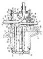
図3〜図7は、第1のケーシング22の部位におけるコネクタ7の断面を示している。
図3に示すように、第1のケーシング22は、電気絶縁性を有するプラスチックによって形成され、その内部にベース部材26が配設されている。ベース部材26は、その先端の突当面70によって支持部材21に位置決めされており、3本のネジ28,29,30によって支持部材21に固定されている。なお、ネジ30は、後述する継手36とベース部材26と支持部材21とを一体に固定している。
【0014】
支持部材21の傾きを防止して正確な位置決めを行なうために、3本のネジ28,29,30は、互いに同一直線上になく、三角形の各頂点を形成するように配置されている。また、ネジ28,29,30の曲がりを防止し且つネジ28,29,30の安定した締め付け作業を確保するために、ネジ28,29,30はベース部材26のビス案内用ガイド支柱97を貫通するように設けられている。なお、ビス案内用ガイド支柱97は、その手元側にビス逃げ用広口部98が設けられており、加工性が良好となっている。
【0015】
アース口金8と吸引口金9と送水口金13と加圧口金14はそれぞれ、第1のケーシング22に設けられた貫通孔81,82,83,84を貫通して、ベース部材26に固定されている。また、ガード12は、第1のケーシング22に設けられた凸部27と、この凸部27に略嵌合して接着固定されるカバー部材85とによって構成されている。
【0016】
ベース部材26に設けられた突当面86には、継手36が位置決めされて当接されている。そして、継手36は、前述したネジ30とビス58(図4参照)とによって、ベース部材26に固定されている。なお、継手36は、吸引口金9に接続される図示しない吸引管路と、送水口金13および加圧口金14に接続される図示しない送気・送水管路とを保持している。
【0017】
支持部材21と第1のケーシング22は、支持部材21と第1のケーシング22との間の水密を保つOリング31を介して接続され、互いに接触しないように位置決めされている。また、アース口金8は、 アース口金8と第1のケーシング22との間の水密を保つOリング38を介して第1のケーシング22に接続され、第1のケーシング22に接触しないように配置されている。また、吸引口金9は、吸引口金9と第1のケーシング22との間の水密を保つOリング39を介して第1のケーシング22に接続され、第1のケーシング22に接触しないように配置されている。また、送水口金13は、送水口金13と第1のケーシング22との間の水密を保つOリング40を介して第1のケーシング22に接続され、第1のケーシング22に接触しないように配置されている。また、加圧口金14は、加圧口金14と第1のケーシング22との間の水密を保つOリング41を介して第1のケーシング22に接続され、第1のケーシング22に接触しないように配置されている。また、継手36と第1のケーシング22は、継手36と第1のケーシング22との間の水密を保つOリング32を介して接続され、互いに接触しないように位置決めされている。
【0018】
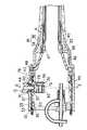
図4に示すように、支持部材21には長方形の内孔71(図7参照)を有する管状の保持部材66が設けられている。この保持部材66は、支持部材21に対して回転不能に接着固定され、送気管19の固定部73を保持している。この場合、固定部73は、図7に示すように、断面が円形の送気管19の手元側外面部分を両側から切り欠く(Dカット)ことによって形成されており、 これによって、送気管19には、保持部材66の内面に接して保持される平坦な2つの当接面72と、 保持部材66の内面の段差部に突き当たる突当面87とが形成される。したがって、送気管19は、その固定部73の当接面72によって保持部材66に回転不能に保持され、その突当面87によって軸方向の位置決めがなされる。なお、送気管19は、固定部73を保持部材66内に引き込み固定する固定部材65(図4参照)によって、支持部材21に固定される。 また、図4に示すように、固定部材65と支持部材21との間にはOリング63が介挿されており、これによって、固定部材65と支持部材21との間が水密に保たれている。また、固定部材65と送気管19との間にはOリング62が介挿されており、これによって、固定部材65と送気管19との間が水密に保たれている。
【0019】
図4に示すように、ライトガイド口金11は、支持部材21を貫通しており、支持部材 21に設けられた突当面89によって軸方向の位置決めがなされている。そして、ライトガイド口金11は、ネジ部88によって、ベース部材26に捩じ込んで固定されている。また、ライトガイド口金11と支持部材21との間にはOリング64が介挿されており、これによって、ライトガイド口金11と支持部材21との間が水密に保たれている。なお、ライトガイド口金11の内部にはライトガイドファイバー51が配設されている。
【0020】
ベース部材26には、挿入部4の先端から導かれたアース線56が固定されている。この場合、アース線56は、アース線56とベース部材26とを電気的に導通させるビス57によって、ベース部材26に固定されている。したがって、アース線56は、ベース部材26を介して、アース口金8に電気的に導通する。
【0021】
図7に示すように、電気接点18には、調光信号等を伝達するケーブル69が半田付けされて電気的に導通している。電気接点18は、略櫛状に形成され、第1のケーシング22に接着固定された保持部材93によってそのフランジ部94が引掛け保持された状態で、第1のケーシング22に固定されている。また、電気接点18と第1のケーシング22との間にはOリング68が介挿されており、これによって、電気接点18と第1のケーシング22との間が水密に保たれている。
【0022】
なお、図4中、59は、第1のケーシング22に設けられ、第1のケーシング22とベース部材26とを回転不能に位置決めする凸部である。また、60は、ベース部材26に設けられ、凸部59と係合して第1のケーシング22とベース部材26とを回転不能に位置決めする凹部である。
【0023】
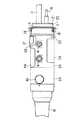
図8および図9は、第2のケーシング23の部位におけるコネクタ7の断面を示している。
図8に示すように、第2のケーシング23は、電気絶縁性を有するプラスチックによって形成されている。第2のケーシング23の内部には、通気口金10が固定される継手37が設けられている。継手37は、ビス53によって継手36に固定されている。継手36と第2のケーシング23は、継手36と第2のケーシング23との間の水密を保つOリング33を介して接続され、互いに接触しないように位置決めされている。また、 継手37と第2のケーシング23は、継手37と第2のケーシング23との間の水密を保つOリング42を介して接続され、互いに接触しないように位置決めされている。また、通気口金10は、通気口金10と第2のケーシング23との間の水密を保つOリング44を介して第2のケーシング23に接続され、第2のケーシング23に接触しないように配置されている。
【0024】
継手37は、ビス48によって、継手37とユニバーサルコード6とを接続する継手46に固定されている。また、継手46は、ビス47によって、ユニバーサルコード6に固定されている。
【0025】
折れ止め16は、インサート金属34の外側にシリコンゴム35をインサート成形して成る。継手46は、ネジ部90によってインサート金属34に捩じ込み固定され、その当接部49によって軸方向の位置決めがなされる。インサート金属34と継手37との間にはOリング43が介挿されており、これによって、インサート金属34と継手37との間が水密に保たれている。また、インサート金属34とユニバーサルコード6との間にはOリング45が介挿されており、これによって、インサート金属34とユニバーサルコード6との間が水密に保たれている。
【0026】
通気口金10は、第2のケーシング23に設けられた貫通孔91を貫通して、継手37に取り付けられている。この場合、通気口金10は、その端部に形成された固定部75が継手37に形成された保持部74に保持されて接着された状態で、保持部74と固定部75とを貫通するネジ50によって継手37に固定される。なお、固定部75は、その当接面92によって、保持部74に回転不能に保持される。
【0027】
また、通気口金10には、接着面積を増やすため、継手37と嵌合する大径の嵌合部79が設けられている。また、通気口金10には、コネクター7内に開口する通気孔80が設けられている。そして、この通気孔80によって、前述した通気アダプターが取り付けられた際、外気とコネクタ7(内視鏡1)内とが連通される。
【0028】
以上説明した第1のケーシング22と第2のケーシング23は、前述したように、支持部材21と折れ止め16との間で挟持される。この時、第1のケーシング22と第2のケーシング23の収納幅は、支持部材21の挟持面95(図3参照)とユニバーサルコード6の挟持面96(図8参照)とによって決定される。すなわち、支持部材21、ベース部材26、継手36、継手37、継手46、折れ止め16の位置で決定される。具体的には、第1のケーシング22と第2のケーシング23の長さの総和は挟持面95,96間の距離よりも小さく設定されており、支持部材21と第1のケーシング22との間には隙間76( 図4参照)が、第1のケーシング22と第2のケーシング23との間には隙間77(図4参照)が、第2のケーシング23と折れ止め16との間には隙間78(図8参照)が形成されるようになっている。したがって、第1のケーシング22と第2のケーシング23は、Oリング31,32,33,42,43,38,39,40,41,44により、支持部材21と折れ止め16との間で保持された状態となっている。
【0029】
図10にはコネクター7の側面図が、図11にはコネクター7の平面図が示されている。図11に示すように、第1のケーシング22には、電気接点18を保護するためのガード52と凸部25とが設けられている。この場合、ガード52の高さcおよび凸部25の高さdは、電気接点18の高さよりも高く設定されている。また、図10に示すように、ガード12は、その高さaが送水口金13および加圧口金14の高さよりも高く設定されており、送水口金13および加圧口金14を保護している。通気口金10は、その高さbがアース口金8および吸引口金9の高さよりも高く設定されており、アース口金8および吸引口金9を保護している。
【0030】
次に、上記構成のコネクタ7の組立方法について説明する。
(1)電気接点18を第1のケーシング22に取り付ける (図4および図7参照)
まず、 ケーブル69が半田付けされる電気接点18の部位に予め半田を付ける。そして、ケーブル69の先端部の被覆を除去して素線を露出し、この露出した素線部分と電気接点18とを半田付けする。次に、電気接点18にOリング68を取り付けるとともに接着剤を塗布し、電気接点18を第1のケーシング22の固定用孔99に挿入する。この状態で、第1のケーシング22に接触される保持部材93の接触面100に接着剤を塗布し、保持部材93を第1のケーシング22の内面に接着する。この時、保持部材93の櫛状部に電気接点18のフランジ部94が引掛かり、電気接点18が第1のケーシング22から抜けなくなる。(2)固定部材150を第1のケーシング22に取り付ける(図4参照)
第1のケーシング22の表面に設けられた保持穴149に、ビス24をねじ込むための固定部材150を接着固定する。
(3)ベース部材26と支持部材21とを第1のケーシング22に組み付ける (図3参照)
まず、第1のケーシング22にベース部材26を図面右側から挿入する。続いて、ケーブル69をベース部材26のガイド穴148(図7参照)に入れる。また、支持部材21に予め保持部材66を接着固定しておき、Oリング31にグリスを塗布し、このグリス付きのOリング31を支持部材21に装着しておく。この状態で、支持部材21を図面左側から第1のケーシング22に装着するとともに、ネジ28,29を図中左側からベース部材26に貫通させて支持部材21にねじ込み、ベース部材26と支持部材21とを固定する。
(4)各種口金を第1のケーシング22に取り付ける(図3参照)
Oリング40にグリスを塗布し、このグリス付きのOリング40を送水口金13に装着する。そして、送水口金13をベース部材26の内側から第1のケーシング22の貫通孔83に挿通して組み付け、固定部材147を第1のケーシング22の外側から送水口金13にねじ込んで、送水口金13をベース部材26と第1のケーシング22とに固定する。
【0031】
Oリング41にグリスを塗布し、このグリス付きのOリング41を加圧口金14に装着する。そして、加圧口金14をベース部材26の内側から第1のケーシング22の貫通孔84に挿通して組み付け、固定部材146を第1のケーシング22の外側から加圧口金14にねじ込んで、加圧口金14をベース部材26と第1のケーシング22とに固定する。
【0032】
Oリング38にグリスを塗布し、このグリス付きのOリング38をアース口金8に装着する。そして、アース口金8を第1のケーシング22の外側から貫通孔81に挿通して組み付け、アース口金8の端部に形成されたネジ部に接着剤を塗布してこれをベース部材26にねじ込み固定する。
【0033】
Oリング39にグリスを塗布し、このグリス付きのOリング39を吸引口金9の固定部材145に装着する。そして、吸引口金9をベース部材26の内側から第1のケーシング22の貫通孔82に挿通して組み付け、固定部材145を第1のケーシング22の外側から吸引口金9にねじ込んで、吸引口金9をベース部材26と第1のケーシング22とに固定する。
(5)継手36の組み付け(図3および図4参照)
まず、Oリング32とOリング33とにグリスを塗布し、これらグリス付きのOリング32,33を継手36に装着する。そして、継手36を図面右側からベース部材26に突き当たるまで第1のケーシング22内に挿入する。そして、ネジ30を、継手36側からベース部材26に挿入して貫通させ、支持部材21にねじ込み、これによって、支持部材21とベース部材26と継手36とを一体的に固定する。
【0034】
次に、ビス58を継手36に貫通させてベース部材26にねじ込み、ネジ30とベース部材26とを固定する。この時、継手36が第1のケーシング22に対して傾かないように、ネジ30とビス58の締め方およびトルクを調整する。
(6)送気管19およびライトガイド口金11を取り付ける(図4参照)
送気管19にチューブ61を装着する。そして、Oリング62にグリスを塗布し、このグリス付きのOリング62を送気管19に装着する。続いて、送気管19を図面右側から第1のケーシング22内に挿入して支持部材21の貫通孔144に挿通する。そして、送気管19の突当面87が保持部材66の内面の段差部に突き当たるまで、送気管19を押し込む。この時、送気管19は、固定部73の当接面72が保持部材66の長方形の内孔71に嵌まり込むことによって、保持部材66に回転不能に保持される。
【0035】
続いて、Oリング63にグリスを塗布し、このグリス付きのOリング63を固定部材65に装着する。 また、送気管19のネジ固定部142に接着剤を塗布し、固定部材65を図面右側から送気管19に挿通させる。そして、支持部材21に突き当たるまで固定部材65を送気管19にねじ込み、固定部材65と送気管19とによって、支持部材21と保持部材66とを挟み固定する。
【0036】
Oリング64にグリスを塗布し、このグリス付きのOリング64をライトガイド口金11に装着する。そして、支持部材21の突当面89に突き当たるまでライトガイド口金11を図面左側から支持部材21の貫通孔143に挿通して、ライトガイド口金11とベース部材26とをネジ部88によって固定する。この場合、ネジ部88には接着剤を塗布しておく。
(7)ガード12の形成等(図3および図4参照)
第1のケーシング22に形成された凸部27の表面およびカバー部材85の内面に接着剤を塗布し、カバー部材85を凸部27に接着固定する。一方、Cリング20を広げて支持部材21に装着する。この場合、Cリング20は、その弾性によって小径に戻り、支持部材21に保持される。また、シール54を第1のケーシング22の表面に貼りつける。
(8)継手37と第2のケーシング23との組み付け(図8参照)
Oリング42とOリング43とにグリスを塗布し、これらグリス付きのOリング42,43を継手37に装着する。そして、継手37を継手36に組み付け、ビス53によって継手36と継手37とを固定する。続いて、第2のケーシング23を図面右側から継手37の外周に被せる。
(9)通気口金10を第2のケーシング23に取り付ける(図8参照)
Oリング44にグリスを塗布し、このグリス付きのOリング44を通気口金10に装着する。そして、通気口金10を,第2のケーシング23の外側から第2のケーシング23の孔91に挿通して、継手37に組み付ける。この時、固定部75と保持部74とが当接面92によって回転不能に組み付けられる。さらに、ネジ50に接着剤を塗布し、図面右側から保持部74を介してネジ50を固定部75にねじ込み固定することにより、ネジ50と保持部74と固定部75とを一体に固定する。
(10)継手46とユニバーサルコード6の組み付け(図8参照)
継手46を継手37に組み付け、ビス48によって継手46と継手37とを固定する。Oリング45にグリスを塗布し、このグリス付きのOリング45をユニバーサルコード6に装着する。 そして、継手46にユニバーサルコード6を挿入し、ビス47によって継手46とユニバーサルコード6とを固定する。ユニバーサルコード6上に被せられる折れ止め16を図面右側から左側に向けて移動させ、ネジ部90を用いてインサート金属34を継手46にねじ込む。この時、継手46の当接部49にインサート金属34が突き当たり、折れ止め16が位置決めされる。
【0037】
以上説明したように、本実施形態の内視鏡コネクタ装置15は、コネクタ7の外装ケース部材を構成するケーシング22,23が、Oリング等の弾性部材のみによって、支持部材21と折れ止め16との間で保持された状態となっている。したがって、ケーシング22,23に大きな挟持力(押圧力)が作用せず、ケーシング22,23の割れ等の破損が防止される。
【0038】
ところで、本実施形態の内視鏡コネクタ装置15のコネクタ7は、一般に、チューブを介して図12に示すように外部装置(光源装置は図示せず)に接続される。すなわち、コネクター7の吸引口金9が吸引管路105を介して吸引ビン101に接続され、吸引ビン101は吸引管路104を介して吸引ポンプ103に接続される。なお、吸引ビン101は蓋102によって栓がされ、吸引ビン101内が密閉空間となっている。この構成では、吸引ビン101内の空気が吸引ポンプ103の吸引作用により吸引管路104を通じて吸引される。したがって、吸引口金9に接続され且つ内視鏡の先端で開口する吸引チャンネルから吸引された吸引物は、吸引管路105を通じて、吸引ビン101内に吸引される。
【0039】
一方、コネクター7の送水口金13は送水管路109を介して送水ビン106に接続され、送水ビン106は加圧管路108を介して加圧口金14に接続される。この場合、送水管路109は送水ビン106に溜められた水中に浸され、加圧管路108の開口端は水面の上方に位置している。なお、送水ビン106は蓋107で栓がされており、送水ビン106内が密閉空間となっている。また、コネクター7の送気管19は加圧口金14と連通しており、送気管19にはポンプ110が接続されている。この構成では、ポンプ110から送気された空気が加圧口金14を通って送水ビン106内に送られ、 送水ビン106内が加圧される。加圧された送水ビン106内の空気は送水ビン106内の水を押し出す。そして、押し出された水は、送水管路109を通じて、送水口金13に接続され且つ内視鏡の先端で開口する送水ノズルに送られ、この送水ノズルから吐き出される。
【0040】
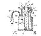
図13は、図12の構成を改善した例を示している。図示のように、吸引送水ビン111は、図12に示した吸引ビン101と送水ビン106とを一体にしたものである。吸引送水ビン111は、吸引ビン部120と送水ビン部121とから成り、吸引ビン部120と送水ビン部121との連通部には活性炭等のフィルター119が設けられている。
【0041】
コネクター7の吸引口金9は吸引管路115を介して吸引ビン部120に接続されている。また、吸引ビン部120は吸引管路114を介して吸引ポンプ103に接続されている。なお、吸引ビン部120は蓋113で栓がされており、吸引ビン部120内が密閉空間となっている。 この構成では、吸引ビン部120内の空気が吸引ポンプ103の吸引作用により吸引管路114を通じて吸引される。したがって、吸引口金9に接続され且つ内視鏡の先端で開口する吸引チャンネルから吸引された吸引物は、吸引管路115を通じて、吸引ビン部120内に吸引される。
【0042】
一方、コネクター7の送水口金13は送水管路117を介して送水ビン部121に接続されている。また、送水ビン部121は加圧管路116を介して加圧口金14に接続されている。 なお、送水ビン部121は蓋112で栓がされており、送水ビン部121内が密閉空間となっている。また、コネクター7の送気管19は加圧口金14と連通しており、送気管19にはポンプ110が接続されている。この構成では、ポンプ110から送気された空気が加圧口金14を通って送水ビン部121内に送られ、送水ビン部121内が加圧される。加圧された送水ビン部121内の空気は送水ビン部121内の水を押し出す。そして、押し出された水は、送水管路117を通じて、送水口金13に接続され且つ内視鏡の先端で開口する送水ノズルに送られ、この送水ノズルから吐き出される。
【0043】
この時、吸引管路115を通じて吸引された吸引物は、吸引管路115の先端に設けられた回収ネット118に収容される。そして、この回収ネット118で固形物と水溶液とがろ過分離されて、水溶液のみが吸引ビン部120内に収納される。吸引ビン部120内の水溶液は、活性炭等のフィルター119によってろ過され、体内に送水可能な水溶液となって送水ビン部121に移動する。
【0044】
このように、図13の構成では、図12の構成と異なり、吸引ビン101が吸引物で一杯にならないため、吸引物を捨てる手間が省ける。また、送水ビン106が空にならないため、給水する手間が省ける。
【0045】
図14は、内視鏡を収容して運搬するケース126を示している。図14の (a)に示すように、ケース126は、蓋部129と、蓋部129にヒンジ結合された底部128とからなる。また、底部128は、内視鏡が収容セットされる溝部127を有する内視鏡保持部134を備えている。この構成では、内視鏡を溝部127に収納した後、蓋部129と底部128とを合わせて運搬状態とする(図14の(b)参照)。この場合、ケース135の運搬は、蓋部129に設けられた取手130を利用して行なわれる。
【0046】
図15は、図14のケース126を改良した例を示している。図15の(a)に示すように、蓋部129には孔部131が設けられ、内視鏡保持部134には蓋部129と底部128とを合わせた状態で孔部131と対向一致する孔部132が設けられている。この構成では、蓋部129と底部128とを合わせて運搬状態にする(図15の(b)参照)と、孔部131,132同士が連通して取手133が形成される。
【0047】
このように、図15の構成では、図14の構成と異なり、取手133がケース126から突き出ないため、ケース126自身を小さくできる。したがって、輸送スペースが削減でき、輸送費用も少なくできる。
【0048】
なお、以上説明してきた技術内容によれば、以下に示すような各種の構成が得られる。
1.内視鏡に接続される接続部材と、前記接続部材の端部に設けられ且つ内視鏡とともに使用される外部装置に着脱自在に接続され、接続部材に内装された要素の少なくとも一部を収納する収納室を形成するコネクタ本体とから成る内視鏡コネクタ装置において、
コネクタ本体は、外装部材を形成するケーシング部材と、ケーシング部材を挟持する保持部材とを有し、
前記保持部材と前記ケーシング部材との間に隙間が形成されていることを特徴とする内視鏡コネクタ装置。
【0049】
2.内視鏡に接続される接続部材と、前記接続部材の端部に設けられ且つ内視鏡とともに使用される外部装置に着脱自在に接続され、接続部材に内装された要素の少なくとも一部を収納する収納室を形成するコネクタ本体とから成る内視鏡コネクタ装置において、
コネクタ本体は、外装部材を形成するケーシング部材と、ケーシング部材を挟持する保持部材とを有し、
前記ケーシング部材は、弾性部材のみを介して、保持部材により挟持されて保持されることを特徴とする内視鏡コネクタ装置。
【0050】
3.接続部材がケーシング部材から突出して設けられ、ケーシング部材が接続部材に対して弾性部材のみによって保持されることを特徴とする第2項に記載の内視鏡コネクタ装置。
4.第1項および第3項に記載の構成を有する内視鏡コネクタ装置。
【0051】
【発明の効果】
以上説明したように、本発明の内視鏡コネクタ装置は、コネクタ本体の外装部材を構成するケーシング部材が、弾性部材のみによって、保持部材に挟持されて保持される。 したがって、ケーシング部材に大きな挟持力(押圧力)が作用せず、ケーシング部材の割れ等の破損が防止される。
【図面の簡単な説明】
【図1】本発明の一実施形態に係わる内視鏡コネクタ装置を備えた内視鏡の全体図である。
【図2】本発明の一実施形態に係る内視鏡コネクタ装置の斜視図である。
【図3】図2の内視鏡コネクタ装置の先端側の縦断面図である。
【図4】図2の内視鏡コネクタ装置の先端側の横断面図である。
【図5】図3のA−A線に沿う断面図である。
【図6】図3のB−B線に沿う断面図である。
【図7】図4のC−C線に沿う断面図である。
【図8】図2の内視鏡コネクタ装置の基端側の縦断面図である。
【図9】(a)は図8のD−D線に沿う断面図、(b)は(a)のX−X線に沿う断面図である。
【図10】図2の内視鏡コネクタ装置の側面図である。
【図11】図2の内視鏡コネクタ装置の平面図である。
【図12】図2の内視鏡コネクタ装置を外部装置に接続した状態を示す図である。
【図13】図12の構成を改良した例を示す図である。
【図14】内視鏡ケースの一例を示す図である。
【図15】図14の構成を改良した例を示す図である。
【符号の説明】
1…内視鏡
6…ユニバーサルコード(接続部材)
7…コネクタ(コネクタ本体)
15…内視鏡コネクタ装置
16…折れ止め(保持部材)
21…支持部材(保持部材)
22,23…ケーシング
31,32,33,42,43,38,39,40,41,44…Oリング[0001]
BACKGROUND OF THE INVENTION
The present invention relates to an endoscope connector device for connecting an external device such as a light source device and an endoscope.
[0002]
[Prior art]
In general, an endoscope is used by being connected to an external device such as a light source device or a control device. The connection between the external device and the endoscope is, for example, an endoscope connector device such as a universal cord having a connector at the tip and connected to the operation portion of the endoscope (refer to Japanese Patent Laid-Open No. 5-269080). Is done through.
[0003]
This type of endoscope connector device has a connector body that is detachably connected to an external device. The connector main body is configured such that one end side of a built-in object such as a light guide or a signal line is accommodated in a plastic exterior case member having electrical insulation. For example, a suction base to which a tube extending from an aspirator as an external device is connected, a water supply base to which a water supply tube is connected, and a grounding cord for grounding an endoscope during high frequency treatment are connected to the side surface of the connector body. There are provided a ground base and a vent base to which an adapter for communicating the inside and outside of the endoscope at the time of ethylene oxide gas sterilization is connected. A base member (made of metal or plastic) for fixing these caps and the like is disposed in the exterior case member. The exterior case member and the base member are held and fixed (assembled) by being held by a plurality of holding members.
[0004]
[Problems to be solved by the invention]
By the way, the exterior case member is made of electrically insulating plastic as described above, so it is very weak against external force such as tightening force, and breakage such as cracks in the state of being sandwiched and assembled by the holding member. May occur.
[0005]
The present invention has been made paying attention to the above circumstances, and an object of the present invention is to provide an endoscope connector device capable of assembling an exterior case member of a connector main body without giving a large clamping force. It is in.
[0006]
[Means for Solving the Problems]
In order to solve the above-described problems, the present invention provides a connection member connected to an endoscope and an external device provided at an end of the connection member and used together with the endoscope. In an endoscope connector device including a connector main body that forms a storage chamber for storing at least a part of elements housed in a member, the connector main body sandwiches the casing member and a casing member that forms an exterior member. A holding member, and only an elastic member is interposed between the holding member and the casing member.And there is a gap between the holding member and the casing member It is characterized by that.
[0007]
DETAILED DESCRIPTION OF THE INVENTION
Hereinafter, embodiments of the present invention will be described with reference to the drawings.
FIG. 1 shows an endoscope. As shown in the drawing, the endoscope 1 is composed of an
[0008]
An
[0009]
FIG. 2 shows the
[0010]
The
[0011]
The
[0012]
The
[0013]
3 to 7 show a cross section of the
As shown in FIG. 3, the
[0014]
In order to prevent tilting of the
[0015]
The
[0016]
The joint 36 is positioned and abutted against the abutting
[0017]
The
[0018]
As shown in FIG. 4, the
[0019]
As shown in FIG. 4, the light guide base 11 passes through the
[0020]
A
[0021]
As shown in FIG. 7, a
[0022]
In FIG. 4,
[0023]
8 and 9 show a cross section of the
As shown in FIG. 8, the
[0024]
The joint 37 is fixed to a joint 46 that connects the joint 37 and the
[0025]
The anti-bending 16 is formed by insert-
[0026]
The
[0027]
In addition, the
[0028]
As described above, the
[0029]
FIG. 10 shows a side view of the
[0030]
Next, a method for assembling the
(1) The
First, solder is applied in advance to the portion of the
A fixing
(3) The
First, the
(4) Various bases are attached to the first casing 22 (see FIG. 3).
Grease is applied to the O-
[0031]
Grease is applied to the O-
[0032]
Grease is applied to the O-
[0033]
Grease is applied to the O-
(5) Assembly of the joint 36 (see FIGS. 3 and 4)
First, grease is applied to the O-
[0034]
Next, the
(6) Attach the
A
[0035]
Subsequently, grease is applied to the O-
[0036]
Grease is applied to the O-
(7) Formation of
Adhesive is applied to the surface of the
(8) Assembly of the joint 37 and the second casing 23 (see FIG. 8)
Grease is applied to the O-
(9) The
Grease is applied to the O-
(10) Assembly of joint 46 and universal cord 6 (see FIG. 8)
The joint 46 is assembled to the joint 37, and the joint 46 and the joint 37 are fixed with
[0037]
As described above, in the
[0038]
Incidentally, the
[0039]
On the other hand, the
[0040]
FIG. 13 shows an example in which the configuration of FIG. 12 is improved. As shown in the figure, the suction water supply bottle 111 is a combination of the
[0041]
The
[0042]
On the other hand, the
[0043]
At this time, the sucked material sucked through the
[0044]
In this way, in the configuration of FIG. 13, unlike the configuration of FIG. 12, the
[0045]
FIG. 14 shows a
[0046]
FIG. 15 shows an example in which the
[0047]
Thus, in the configuration of FIG. 15, unlike the configuration of FIG. 14, since the handle 133 does not protrude from the
[0048]
In addition, according to the technical content demonstrated above, the various structures as shown below are obtained.
1. A connecting member connected to the endoscope, and detachably connected to an external device provided at the end of the connecting member and used together with the endoscope, and stores at least a part of the elements incorporated in the connecting member In an endoscope connector device comprising a connector body that forms a storage chamber,
The connector body has a casing member that forms an exterior member, and a holding member that sandwiches the casing member.
An endoscope connector device, wherein a gap is formed between the holding member and the casing member.
[0049]
2. A connecting member connected to the endoscope, and detachably connected to an external device provided at the end of the connecting member and used together with the endoscope, and stores at least a part of the elements incorporated in the connecting member In an endoscope connector device comprising a connector body that forms a storage chamber,
The connector body has a casing member that forms an exterior member, and a holding member that sandwiches the casing member.
The endoscope connector device, wherein the casing member is held and held by a holding member only through an elastic member.
[0050]
3. The endoscope connector apparatus according to
4). An endoscope connector apparatus having the configuration according to any one of
[0051]
【The invention's effect】
As described above, in the endoscope connector device of the present invention, the casing member constituting the exterior member of the connector main body is held and held between the holding members only by the elastic members. Therefore, a large clamping force (pressing force) does not act on the casing member, and breakage such as cracking of the casing member is prevented.
[Brief description of the drawings]
FIG. 1 is an overall view of an endoscope provided with an endoscope connector device according to an embodiment of the present invention.
FIG. 2 is a perspective view of an endoscope connector device according to an embodiment of the present invention.
3 is a longitudinal sectional view of the distal end side of the endoscope connector device of FIG. 2. FIG.
4 is a cross-sectional view of the distal end side of the endoscope connector device of FIG. 2. FIG.
5 is a cross-sectional view taken along line AA in FIG.
6 is a cross-sectional view taken along line BB in FIG.
7 is a cross-sectional view taken along the line CC of FIG.
8 is a longitudinal sectional view of the proximal end side of the endoscope connector device of FIG. 2. FIG.
9A is a cross-sectional view taken along line DD in FIG. 8, and FIG. 9B is a cross-sectional view taken along line XX in FIG.
10 is a side view of the endoscope connector device of FIG. 2. FIG.
FIG. 11 is a plan view of the endoscope connector device of FIG. 2;
12 is a view showing a state where the endoscope connector device of FIG. 2 is connected to an external device. FIG.
13 is a diagram illustrating an example in which the configuration of FIG. 12 is improved.
FIG. 14 is a diagram illustrating an example of an endoscope case.
15 is a diagram showing an example in which the configuration of FIG. 14 is improved.
[Explanation of symbols]
1 ... Endoscope
6 ... Universal cord (connection member)
7. Connector (connector body)
15 ... Endoscope connector device
16 ... Bending prevention (holding member)
21: Support member (holding member)
22, 23 ... casing
31, 32, 33, 42, 43, 38, 39, 40, 41, 44 ... O-ring
Claims (1)
Translated fromJapanese前記接続部材の端部に設けられ且つ内視鏡とともに使用される外部装置に着脱自在に接続され、接続部材に内装された要素の少なくとも一部を収納する収納室を形成するコネクタ本体と
から成る内視鏡コネクタ装置において、
前記コネクタ本体は、
外装部材を形成するケーシング部材と、
前記ケーシング部材を挟持する保持部材と
を有し、前記保持部材と前記ケーシング部材との間に弾性部材のみが介挿され、かつ、前記保持部材と前記ケーシング部材との間に隙間を有することを特徴とする内視鏡コネクタ装置。A connection member connected to the endoscope;
A connector main body that is provided at an end of the connection member and is detachably connected to an external device used together with an endoscope, and forms a storage chamber for storing at least a part of the elements housed in the connection member. In an endoscope connector device,
The connector body is
A casing member forming an exterior member;
A holding member for sandwiching the casing member, and only an elastic member is inserted between theholding member and the casing member, and a gap is provided between the holding member and the casing member. Endoscope connector device characterized.
Priority Applications (1)
| Application Number | Priority Date | Filing Date | Title |
|---|---|---|---|
| JP08662097AJP3850097B2 (en) | 1997-04-04 | 1997-04-04 | Endoscope connector device |
Applications Claiming Priority (1)
| Application Number | Priority Date | Filing Date | Title |
|---|---|---|---|
| JP08662097AJP3850097B2 (en) | 1997-04-04 | 1997-04-04 | Endoscope connector device |
Publications (2)
| Publication Number | Publication Date |
|---|---|
| JPH10276963A JPH10276963A (en) | 1998-10-20 |
| JP3850097B2true JP3850097B2 (en) | 2006-11-29 |
Family
ID=13892076
Family Applications (1)
| Application Number | Title | Priority Date | Filing Date |
|---|---|---|---|
| JP08662097AExpired - Fee RelatedJP3850097B2 (en) | 1997-04-04 | 1997-04-04 | Endoscope connector device |
Country Status (1)
| Country | Link |
|---|---|
| JP (1) | JP3850097B2 (en) |
Families Citing this family (6)
| Publication number | Priority date | Publication date | Assignee | Title |
|---|---|---|---|---|
| JP4618928B2 (en)* | 2001-04-19 | 2011-01-26 | Hoya株式会社 | Endoscope display |
| JP2009142520A (en)* | 2007-12-17 | 2009-07-02 | Olympus Medical Systems Corp | Endoscopic instrument |
| EP2303100B1 (en) | 2008-04-16 | 2020-02-12 | United States Endoscopy Group, Inc. | Adaptor for a water bottle of an endoscope |
| CN102686142B (en) | 2009-08-31 | 2014-10-29 | 布拉蔻诊断公司 | In-line gas adapter for endoscopic apparatus |
| WO2011032067A1 (en) | 2009-09-14 | 2011-03-17 | Bracco Diagnostics Inc. | In-line gas adaptor for endoscopic apparatus |
| EP2830477A1 (en) | 2012-03-30 | 2015-02-04 | Bracco Diagnostics Inc. | Water bottle cap assemblies for an endoscopic device |
- 1997
- 1997-04-04JPJP08662097Apatent/JP3850097B2/ennot_activeExpired - Fee Related
Also Published As
| Publication number | Publication date |
|---|---|
| JPH10276963A (en) | 1998-10-20 |
Similar Documents
| Publication | Publication Date | Title |
|---|---|---|
| CN107809940B (en) | Endoscope with a detachable handle | |
| CN107771049B (en) | Endoscope comprising a chassis with a housing structure | |
| RU2050153C1 (en) | Device for performing blood vessel puncture | |
| US5020539A (en) | Ultrasonic endoscope apparatus | |
| US7014340B2 (en) | Illumination assembly having fluid-tight seal | |
| US4669449A (en) | Submergible laryngoscope metallic housing for fiber optics power source | |
| JP3850097B2 (en) | Endoscope connector device | |
| JPH07323001A (en) | Endoscope | |
| CN105596028B (en) | Ultrasonic endoscope cover and ultrasonic endoscope | |
| US5321783A (en) | Mount for optical fibers | |
| JPH0349405B2 (en) | ||
| EP0564565B1 (en) | Multipurpose optical fiber cable connector | |
| JP6923625B2 (en) | Medical or dental equipment with RFID memory tag | |
| JP3423499B2 (en) | Endoscope | |
| EP4056100A1 (en) | A tip part for a medical insertion vision device | |
| JPH0372974A (en) | Liquid spraying device | |
| JPH0345682Y2 (en) | ||
| JPH07191266A (en) | Waterproof cap for endoscope | |
| JPH08140924A (en) | End of endoscope | |
| EP0119085A2 (en) | Photoelectric brain scanner and its use | |
| JP3258440B2 (en) | Endoscope | |
| CN219306663U (en) | Photoacoustic endoscope and endoscope system | |
| JPH0452729Y2 (en) | ||
| JPH0644906B2 (en) | Ultrasound endoscope | |
| JP2001258831A (en) | Image forming device |
Legal Events
| Date | Code | Title | Description |
|---|---|---|---|
| A621 | Written request for application examination | Free format text:JAPANESE INTERMEDIATE CODE: A621 Effective date:20040227 | |
| A977 | Report on retrieval | Free format text:JAPANESE INTERMEDIATE CODE: A971007 Effective date:20051201 | |
| A131 | Notification of reasons for refusal | Free format text:JAPANESE INTERMEDIATE CODE: A131 Effective date:20051213 | |
| A521 | Written amendment | Free format text:JAPANESE INTERMEDIATE CODE: A523 Effective date:20060210 | |
| TRDD | Decision of grant or rejection written | ||
| A01 | Written decision to grant a patent or to grant a registration (utility model) | Free format text:JAPANESE INTERMEDIATE CODE: A01 Effective date:20060822 | |
| A61 | First payment of annual fees (during grant procedure) | Free format text:JAPANESE INTERMEDIATE CODE: A61 Effective date:20060829 | |
| FPAY | Renewal fee payment (event date is renewal date of database) | Free format text:PAYMENT UNTIL: 20090908 Year of fee payment:3 | |
| FPAY | Renewal fee payment (event date is renewal date of database) | Free format text:PAYMENT UNTIL: 20100908 Year of fee payment:4 | |
| FPAY | Renewal fee payment (event date is renewal date of database) | Free format text:PAYMENT UNTIL: 20110908 Year of fee payment:5 | |
| FPAY | Renewal fee payment (event date is renewal date of database) | Free format text:PAYMENT UNTIL: 20120908 Year of fee payment:6 | |
| LAPS | Cancellation because of no payment of annual fees |