JP3849863B2 - Roof material integrated solar cell module - Google Patents
Roof material integrated solar cell moduleDownload PDFInfo
- Publication number
- JP3849863B2 JP3849863B2JP2002162793AJP2002162793AJP3849863B2JP 3849863 B2JP3849863 B2JP 3849863B2JP 2002162793 AJP2002162793 AJP 2002162793AJP 2002162793 AJP2002162793 AJP 2002162793AJP 3849863 B2JP3849863 B2JP 3849863B2
- Authority
- JP
- Japan
- Prior art keywords
- solar cell
- roof
- cell module
- material block
- wiring
- Prior art date
- Legal status (The legal status is an assumption and is not a legal conclusion. Google has not performed a legal analysis and makes no representation as to the accuracy of the status listed.)
- Expired - Fee Related
Links
Images


Classifications
- Y—GENERAL TAGGING OF NEW TECHNOLOGICAL DEVELOPMENTS; GENERAL TAGGING OF CROSS-SECTIONAL TECHNOLOGIES SPANNING OVER SEVERAL SECTIONS OF THE IPC; TECHNICAL SUBJECTS COVERED BY FORMER USPC CROSS-REFERENCE ART COLLECTIONS [XRACs] AND DIGESTS
- Y02—TECHNOLOGIES OR APPLICATIONS FOR MITIGATION OR ADAPTATION AGAINST CLIMATE CHANGE
- Y02B—CLIMATE CHANGE MITIGATION TECHNOLOGIES RELATED TO BUILDINGS, e.g. HOUSING, HOUSE APPLIANCES OR RELATED END-USER APPLICATIONS
- Y02B10/00—Integration of renewable energy sources in buildings
- Y02B10/10—Photovoltaic [PV]
- Y—GENERAL TAGGING OF NEW TECHNOLOGICAL DEVELOPMENTS; GENERAL TAGGING OF CROSS-SECTIONAL TECHNOLOGIES SPANNING OVER SEVERAL SECTIONS OF THE IPC; TECHNICAL SUBJECTS COVERED BY FORMER USPC CROSS-REFERENCE ART COLLECTIONS [XRACs] AND DIGESTS
- Y02—TECHNOLOGIES OR APPLICATIONS FOR MITIGATION OR ADAPTATION AGAINST CLIMATE CHANGE
- Y02E—REDUCTION OF GREENHOUSE GAS [GHG] EMISSIONS, RELATED TO ENERGY GENERATION, TRANSMISSION OR DISTRIBUTION
- Y02E10/00—Energy generation through renewable energy sources
- Y02E10/50—Photovoltaic [PV] energy
Landscapes
- Photovoltaic Devices (AREA)
- Roof Covering Using Slabs Or Stiff Sheets (AREA)
Description
Translated fromJapanese【0001】
【発明の属する技術分野】
本発明は、住宅の屋根に取付けて太陽エネルギーを電気に変える太陽光発電用の屋根材一体型太陽電池モジュールに関し、詳しくは太陽電池モジュールの発電出力を取り出す配線構造に係わる。
【0002】
【従来の技術】
近年になり、地球環境の問題からクリーンなエネルギー源として太陽電池が注目されており、住宅の屋根面を利用してここに太陽電池モジュールを設置する太陽光発電装置の導入が国の補助金政策もあって急速に進んでいる。
【0003】
また、その形態としては既設の屋根の上に架台を設けて太陽電池モジュールを設置する方式も知られているが、最近では美観性,デザイン面から太陽電池モジュール自身に屋根材の機能を持たせて屋根の野地板に直接取付けるようにした屋根材一体型太陽電池モジュールの普及が進んでいる。
【0004】
この屋根材一体型太陽電池モジュールは、例えばプラスチックフィルム基板にアモルファスシリコン層,集電電極,透明電極などを成層した光電変換素子を封止材,表面保護材で封止してなる太陽電池を、モジュール基台を兼ねた板状の屋根材ブロック(金属瓦板)に重ねて一体化した上で、この屋根材ブロックから太陽電池の出力リード線を引き出した構造になるもので、前記屋根材ブロックには通常の金属瓦板と同様にその周縁に沿って縁曲げ係合部を形成しておき、太陽電池モジュールをアレイ状に並べて屋根に布設する際に、前記縁曲げ係合部を介して隣接する太陽電池モジュールの屋根材ブロックとの間を連結して通常の屋根瓦と同様な雨仕舞の機能を持たせるようにし、さらに各太陽電池モジュールから引き出した太陽電池の出力リード線をケーブルなどの外部配線に接続して屋内に設置したパワーコンディショナー(インバータ装置)に導き、太陽電池で発電した電気(直流)を交流に変換して住宅で使用する負荷への給電,および商用電源との連系を図るようにしている。
【0005】
次に、住宅の屋根に葺く屋根材一体型太陽電池モジュールの基本的なレイアウトおよびその配線構造を模式図として図11に示す。図において、1は屋根の野地板、2は屋根一体型太陽電池モジュール、3,4は各太陽電池モジュール1に接続した+極,−極側の集電用外部配線(ケーブル,あるいは専用の配線ダクトに通した配線した電線)であり、アレイ状に並べて野地板1の表面に布設した多数枚の太陽電池モジュール2の間を縫うように外部配線3,4を引回し配線した上で、この外部配線3,4に各太陽電池モジュール1から引き出した+極,−極の出力リード線5,6を並列に接続するようにしている。
【0006】
この場合に、各太陽電池モジュール2に接続した外部配線3,4を屋根の表面側に露呈して引き回し配線すると、外部配線が人目に触れて建屋の美観を損なうおそれがあることから、通常は外部配線3,4が人目に触れないように屋根に葺いた屋根材一体型太陽電池モジュール2の裏面側に敷設した上で、この外部配線3,4に各太陽電池モジュール2から裏面に引き出した出力リード線5,6を接続するようにした配線方式が採用されている。
【0007】
次に、前記の配線方式に対応する太陽電池モジュール2の従来構造例を図12(a),(b) に示す。図において、7は太陽電池、8は太陽電池7と一体化した屋根材ブロック(モジュール基台を兼ねた金属瓦板)、9はモジュールの端子箱である。ここで、太陽電池7は、光電変換素子7aの上下両面を封止材(EVA(エチレンビニルアセテート))7b,7cで封止し、さらに受光面側に透光性の耐候保護材(ETFE(エチレン−四フッ化エチレン樹脂)7dを被着した構成になり、この太陽電池7を金属製(あるいは硬質プラスチック製)の屋根材ブロック8の上面に重ねた上で、真空ラミネータなどを使って一体に接合するようにしている。また、屋根材ブロック8には、一般的な金属瓦板と同様にその周縁にコ字形に折り曲げた縁曲げ係合部8a〜8dが形成されており、この縁曲げ係合部同士を絡ませるように係合させて隣接する太陽電池モジュールの屋根材ブロックと連結し、モジュール間の継ぎ目から雨が裏側に浸入しないように雨仕舞している。なお、8eは屋根材ブロック8を屋根の野地板1(図11参照)に釘止めするために耳部に穿孔した釘穴である。
【0008】
一方、前記の端子箱9は屋根材ブロック8の背面側の中央に取付けてあり、光電変換素子7aの出力電極に接続した出力リード線5,6を屋根材ブロック8の底面に穿孔した貫通穴を通して端子箱9に引出し、ここでケーブル10,11に接続して外部配線と接続するようにしている。なお、10a,11aは図11に示した外部配線3,4に接続するための接続端子、12は端子箱9に充填して屋根材ブロック8に穿孔したリード線通し穴に外部から雨水が浸入するのを防止する封止樹脂である。
【0009】
【発明が解決しようとする課題】
図12(a),(b) に示した従来構造の太陽電池モジュール2は、太陽電池7の出力リード線5,6をモジュールの背面側に引き出して外部配線と接続するようにしているので、太陽電池モジュールを屋根に葺いた施工後の状態で配線部材が人目に触れることがないが、耐候性,信頼性の面で次記のような問題点が残る。
【0010】
すなわち、端子箱9を屋根部材ブロック8の背面に設置していることから、出力リード線5,6を端子箱9に引き出すには、屋根材ブロック8の底面に貫通穴を開けてここにリード線を通す必要がある。したがって、このままでは前記穴を通じて外部から回り込んだ雨水が浸入し、出力リード線5,6を伝って太陽電池7の内部に浸透するおそれがある。そこで、従来構造では図示のように端子箱9に封止樹脂12を充填して太陽電池7への水の浸入を防ぐように措置を施している。
【0011】
しかしながら、太陽電池モジュールを10〜20年に亘る中長期的に使用すると、端子箱9に充填した封止樹脂12の経年劣化,気温の変化に伴うヒートサイクルなどによりその封止機能が低下することが避けられない。このために、端子箱9,屋根材ブロック8の底面に穿孔したリード線通し穴を通じて外部から浸入した雨水が太陽電池7の内部に浸透して光電変換素子7aを構成している材料を腐食し、これにより絶縁抵抗の低下,剥離,あるいはクラックが発生して発電性能を低下させるような不具合が生じる。
【0012】
なお、長期間に亘る太陽電池モジュールの数多い運転実績の中で、その発電性能低下の原因について調査した結果からも、端子箱からの水浸透に起因するトラブル例が一番多いことが確認されている。
【0013】
本発明は上記の点に鑑みなされたものであり、屋根に布設した施工後の外観性を損なうおそれがなく、かつ中長期的な使用でも太陽電池の内部に雨水が浸入するおそれがなく、しかも屋根に布設する際の配線の施工が簡単に行えるように配線構造を改良した信頼性の高い屋根材一体型太陽電池モジュールを提供することを目的とする。
【0014】
【課題を解決するための手段】
上記目的を達成するために、本発明によれば、光電変換素子を封止材,表面保護材で封止した太陽電池を、モジュール基台を兼ねた板状の屋根材ブロックの上面に重ねて一体化し、該屋根材ブロックから太陽電池に接続した出力リード線を引き出した屋根材一体型太陽電池モジュールであり、前記屋根材ブロックはその周縁に沿って縁曲げ係合部を形成し、該縁曲げ係合部を介して隣接する太陽電池モジュールの屋根材ブロックと連結するようにしたものにおいて、
第1の発明では、各モジュールごとに、太陽電池に接続した出力リード線を前記縁曲げ係合部を横切る方向に伝って屋根材ブロックの側方に引出し、隣接する太陽電池モジュールの屋根材ブロックと連結した状態で、互いに重なり合う縁曲げ係合部の間を配線経路として、出力リード線の先端をモジュールの背面側に引き出した上で、ここに配線した外部配線と接続するよう構成する(請求項1)。
【0015】
上記の構成によれば、屋根材ブロック自身にリード線を引き出す貫通穴を穿孔することなしに、太陽電池の出力リード線を隣接する太陽電池モジュールとの連結状態で重なり合う縁曲げ係合部の間を通して屋根材ブロックの背面側に引出し、この位置でモジュールの背面側に敷設した外部配線と接続することできる。これにより、太陽電池モジュールの出力リード線,および各モジュール間を縫って屋根に敷設した外部配線が、モジュール受光面側に露呈して美観を損ねることがなく、しかも屋根材ブロックには出力リード線を通す貫通穴がないので、従来構造のように貫通穴を通して外部から雨水が太陽電池の内部に浸透するおそれもなくなって太陽電池モジュールの信頼性が向上する。
【0016】
さらに、前記構成の実施態様として、出力リード線を可撓性のある導電金属板,もしくは金属箔とし、その周面を弾性を有する耐候保護材で被覆する(請求項2)ことにより、隣接する太陽電池モジュールの屋根材ブロックと連結する際の施工で、縁曲げ係合部同士を重ねて加圧密着させても、出力リード線に被覆した弾性保護材によって連結部の雨仕舞機能,および高い耐候性を確保することかできる。
【0017】
また、第2の発明では、各モジュールごとに、屋根材ブロックの周縁に形成した縁曲げ係合部に沿ってその内側に母配線を布設し、この母配線に太陽電池から引き出した出力リード線を接続した上で、母配線の両端を屋根材ブロックのコーナー部に引き出しておき、隣接する太陽電池モジュールの屋根材ブロックと連結する際に各モジュールから引き出した母配線同士を縦続(カスケード)接続するようにする(請求項3)。
【0018】
この構成によれば、第1の発明と同様に屋根材ブロックに太陽電池の出力リード線を通す穴がないので美観性,信頼性を確保できるほか、太陽電池モジュールを屋根に葺く現場での施工時に、アレイ状に並べた太陽電池モジュールとの間を連結する際に、各モジュールごとに屋根材ブロックの内側にあらかじめ組み込んでおいた母配線の接続端子(コネクタ)の間を順に縦続接続することにより、別な外部配線を使わずに太陽電池モジュールの一列分の外部配線が済むことになり、施工現場で行う外部配線の作業が簡単に行える。
【0019】
また、前記した第2の発明の実施態様として、次記のような構成がある。
【0020】
(1) 太陽電池モジュールごとに、母配線をその配線経路に沿って屋根材ブロックの底面に形成した凹溝に布設する(請求項4)。この構成により、母配線と屋根材ブロックに搭載した太陽電池との間に高さ方向の組立段差を確保し、モジュール組立工程で太陽電池本体から側方に引き出した出力リード線を母配線の導体上面に重ね合わせて簡単に接続(はんだ付)することができる。
【0021】
(2) 前記の母配線を太陽電池,出力リード線と一括して保護材で封止する(請求項5)。この構成により、製作時にはこれら各部材を同じ工程で一体化して屋根材ブロックに搭載,接合できるとともに、母配線の高い絶縁性,耐候性も確保できる。
【0022】
(3) さらに、前記の母配線を、屋根材ブロックに対して上下の向きに敷設する(請求項6)、あるいは屋根材ブロックに対して左右の向きに敷設する(請求項7)。
【0023】
このように、屋根材一体型太陽電池モジュールに内蔵した母配線の敷設の向きを、縦向きあるいは横向きにした2種類のタイプのモジュールを用意しておくことにより、住宅屋根の形,屋根に葺くモジュールの基数,およびその配列パターンなど、現場の状況に応じて外部配線の施工に有利なタイプのモジュールを選択できる。
【0024】
【発明の実施の形態】
以下、本発明の実施の形態を図1〜図10に示す図示実施例に基づいて説明する。なお、図示の各実施例において図11,図12に対応する同一部材には同じ符号を付してその詳細な説明は省略する。
【0025】
〔実施例1〕
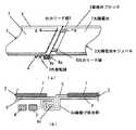
まず、本発明の請求項1,2に対応する実施例を図1〜図4で説明する。この実施例においては、図1(a),(b) で示すように、太陽電池7と一体化した屋根材ブロック(金属瓦板)8にはその左右側縁を裏側へ折り曲げたコ字形の縁曲げ係合部8a,8cが形成されており、太陽電池モジュール2を屋根に葺く際に、隣接する太陽電池ブロック2の屋根材ブロック8との間で前記縁曲げ係合部8aと8cを絡ませて連結するようにしている。
【0026】
また、太陽電池7からは、図3のように+極,−極の出力リード線5,6を側方に引き出しておく。この出力リード線5,6には厚さ0.4mm程度の可撓性のある薄い銅板,あるいは銅箔を採用し、その周面を例えばPET(ポリエチレンテレフタレート)で絶縁保護した上で、一端を太陽電池7の出力電極に接合する。また、太陽電池7を屋根材ブロック8の上面に重ねて一体化したモジュールの組立状態で、太陽電池7から引き出した出力リード線5,6を前記した縁曲げ係合部8aの内面に添わせるように折り曲げて、係合部を横切る方向からモジュールの側方に引き出しておく。
【0027】
そして、隣接する太陽電池モジュール2と連結する際には、図1(b) で表すように縁曲げ係合部8aとこれに係合する隣接モジュールの縁曲げ係合部8cとの間の重なり面を配線経路として、出力リード線5,6を縁曲げ係合部8aと8cの間に挟み込んで隣接する太陽電池モジュール2の裏面側に引き出す。
【0028】
一方、多数枚の太陽電池モジュール2をアレイ状に並べて屋根に葺く際には、図4で示すように太陽電池モジュール2の配列に合わせて野地板1の上に集電用の外部配線3,4をあらかじめ配線しておき、前記のように隣接モジュールとの連結状態で裏面側に引き出した出力リード線5,6をその極性(+,−)に対応する外部配線3,4に接続する。
【0029】
この配線構造によれば、太陽電池モジュール2の屋根材ブロック8に対して、従来構造(図12参照)のようにリード線引出し穴を穿孔することなく、隣接モジュールとの間の連結部で縁曲げ係合部8aと8cの間を通して出力リード線5,6をモジュールの背面側に引き出した上で、前記の外部配線3,4と接続することができる。しかも、モジュールの連結状態では、図示のように縁曲げ係合部8aと8cとが絡み合って密着状態に係合し、その間に挟み込んだ出力リード線5,6の配線経路が迷路状となるので雨仕舞機能を損なうことがない。
【0030】
なお、屋根葺き施工に際しては、隣接するモジュールとの間の継ぎ目から雨水が浸入するのを確実に防ぐために、縁曲げ係合部8aと8cを結合した状態でその連結部に強く締めつけて密着させるようにしており、このために出力リード線5,6が強く圧迫されることになる。
【0031】
そこで、このような状況でも長期間安定した耐候性と信頼性を確保させるために、図2に示す実施例では、隣接するモジュールの間で縁曲げ係合部8aと8cの間を通じて裏面側に引き出した出力リード線5,6を挟んで、その上下両面に高い耐候性と弾性を有するシリコーンゴム13を保護材として被覆している。これにより、縁曲げ係合部8aと8cとの連結部を強く締めつけても、シリコーンゴム13の弾性により、モジュール間の継ぎ目の雨仕舞機能が劣化するおそれがなく、長期間に亘り高い耐候性と信頼性を確保できる。
【0032】
〔実施例2〕
次に、本発明の請求項3〜6に対応する実施例を図5〜図10で説明する。この実施例においては、図12に示した従来の太陽電池モジュールと比べて、次記のよう母配線を組み込んだ構成になる。
【0033】
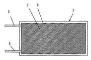
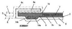
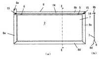
すなわち、図5〜図7で示すように、屋根材ブロック8の底面には、その一方(左側)の側縁に形成した縁曲げ係合部8aに沿ってその内側に凹溝部8fが形成されており、この凹溝部8fに+極,−極に対応する2本の導体14aと14bを対にした母配線14を敷設した上で、その両端を屋根材ブロック8の上下コーナー部に引き出してここに接続端子(コネクタ)15を取付けている。さらに、この屋根材ブロック8の上に載置した太陽電池7から側方に引き出した出力リード線5,6を、その極性を合わせて前記導体14a,14bに接続する。
【0034】
この場合に、図6,図7で示すように太陽電池7の光電変換素子7aの出力端子から側方に引き出した出力リード線(銅箔)5,6はその先端部を、一段低い位置に敷設されている母配線14の導体14a,14bの上面に重ね合わせ接合する。なお、図7において、出力リード線6と交差する異極の導体14aにはその上面に絶縁フィルム16は挟んで絶縁するようにしている。さらに、この実施例では、後記のように太陽電池7の組立工程で母配線14および出力リード線5,6を一括して太陽電池の封止材7bで封止するようにしている。
【0035】
そして、図4で述べたように多数枚の太陽電池モジュール2をアレイ状に配列して屋根に布設する際には、上下列に並ぶモジュールの間で各太陽電池モジュール2ごとにその屋根材ブロック8のコーナー部に引き出した前記母配線14の接続端子(コネクタ)15を、隣接するモジュールに内装した母配線の接続端子に差し込んで縦続接続する。これにより、上下一列に並ぶモジュールの間で母配線14同士が直列に連なって外部配線を構成する。したがって、施工の際に別な外部配線を敷設し、かつ上下一列に並ぶモジュールの間でその出力リード線と接続する面倒な手間が必要なく、現場での配線作業を大幅に簡略化できる。しかも、これら配線部材は全て太陽電池モジュール2の内部に納まっていて屋根の表面側に露呈することがないので、美観性と耐候性が確保できる。
【0036】
次に、発明者等が製作した屋根材一体型太陽電池モジュール2の製造手順について述べる。まず、厚さ0.4mmのガルバリウム鋼板を用意し、屋根材ブロック8に対応した所定サイズに裁断し、次にモジュールに内蔵する母配線14の配線経路に沿って深さ1.5mmの凹溝部8fを加工した。その後に太陽電池7の封止材7bとして厚さ0.6mmのEVA(エチレンビニルアセテート)のシートを鋼板の上に重ね、続いて母配線14の導体14a,14bとしてはんだ処理した厚さ0.2mmの銅製の平板を配置し、両面テープでEVAの上に仮止めした。次に、所定サイズに裁断したフィルム型太陽電池の出力電極に厚さ0.1mmの銅箔で作った出力リード線5,6をはんだ付けしたものをEVAの上に重ね、出力リード線5,6の先端と先に敷設した母配線14との間をはんだ付した。なお、図7に示した絶縁フィルム16として、厚さ0.5mmのカプトンシートを使用した。その後に、前記のEVAとは別にもう一枚のEVAを重ね、さらにその上に表面保護材7dとして厚さ0.025mmのETFE(エチレン−四フッ化エチレン樹脂)のシートを重ねた。
【0037】
その後に、前記の仮組立体を真空ラミネータで約40分加熱処理し、太陽電池7,屋根材ブロック8の鋼板,および母配線14の間を結合して一体化した後、鋼板の周縁を板金加工して縁曲げ係合部8a〜8dを形成し、最後に屋根材ブロック8のコーナー部に引き出した母配線14の両端に接続端子15として差込み式コネクタを取付けて屋根材一体型太陽電池モジュールを完成した。
【0038】
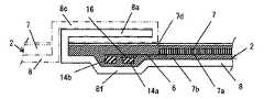
次に、前記した屋根材一体型太陽電池モジュール2の配線構造の一部を変更した応用実施例を図8,図9に示す。この実施例では、母配線14として2本の導体(芯線)14a,14bを絶縁物のPET樹脂14cで被覆した2芯フラットケーブルを使用し、出力リード5,6と接続する箇所で芯線に被覆した絶縁被覆を除去した上ではんだ17で接合するようにしている。
【0039】
〔実施例3〕
図10は本発明の請求項7に対応する実施例を示すものである。すなわち、図5に示した先記の実施例では、母配線14を屋根材ブロック8の左側縁の縁曲げ係合部8aに沿って上下方向に敷設しのに対して、この実施例では母配線14を屋根材ブロック8の上縁側に形成した縁曲げ係合部8bに沿ってその内側に敷設し、その両端を屋根材ブロック8の左右両端のコーナー部に引き出した上で、母配線14と太陽電池7から引き出した出力リード線5,6と接続している。
【0040】
この構成によれば、図4のように多数枚の太陽電池モジュール2を縦横に並べて屋根に布設した状態で、横一列に並ぶモジュールの間を前記の母配線14により接続して外部配線することができる。
【0041】
このように、屋根材一体型太陽電池モジュール2に内装した母配線14の敷設の向きを、図4の縦向き,あるいは図10の横向きにした2種類のタイプの屋根材一体型太陽電池モジュールを用意しておくことにより、太陽電池モジュールを設置する屋根の形,モジュールの基数,およびその配列パターンなど、施工現場の状況に応じて外部配線の施工がし易いタイプのモジュールを選択することかできる。
【0042】
【発明の効果】
以上述べたように、本発明によれば次記の効果を奏する。
【0043】
(1) 請求項1の第1の発明によれば、屋根材ブロック自身にリード線を引き出す貫通穴を穿孔することなしに、太陽電池の出力リード線を隣接する太陽電池モジュールとの連結状態で、縁曲げ係合部の間を通して屋根材ブロックの背面側に引出し、この位置でモジュールの背面側に別途敷設した外部配線と接続することできる。これにより、太陽電池モジュールの出力リード線,および各モジュール間を縫って屋根に敷設した外部配線が、モジュール受光面側に露呈して美観を損ねることがなく、しかも屋根材ブロックには出力リード線を通す貫通穴がないので、従来構造のように貫通穴を通して外部から雨水が太陽電池の内部に浸透するおそれもなくなって太陽電池モジュールの信頼性が向上する。
【0044】
(2) 請求項3の第2の発明によれば、前記した第1の発明と同様に屋根材ブロックに太陽電池の出力リード線を通す穴がないので美観性,信頼性を確保できるほか、太陽電池モジュールを屋根に葺く施工時に、アレイ状に並べた太陽電池モジュールとの間を連結する際に、各モジュールごとに屋根材ブロックにあらかじめ組み込んでおいた母配線の間を順に接続することにより、別な外部配線を使わずに太陽電池モジュールの一列分を相互接続することができ、これにより施工現場で行う外部配線の作業を大幅な簡略化できる。
【0045】
(3) さらに、第2の発明について、屋根材一体型太陽電池モジュールに内蔵した母配線の配置の向きを、請求項6の縦向き,請求項7の横向きに定めた2種類のタイプのモジュールを用意しておくことにより、太陽電池モジュールを設置する屋根の形,モジュールの数,およびその配列パターンなど、現場の状況に応じて外部配線のし易いタイプのモジュールを選択することか可能となる。
【図面の簡単な説明】
【図1】本発明の実施例1に対応する屋根材一体型太陽電池モジュールの配線構造図であり、(a) は隣接するモジュールと連結した状態の斜視図、(b) は(a) の矢視A−Aの拡大断面図
【図2】図1(b) と異なる実施例の拡大断面図
【図3】屋根材一体型太陽電池モジュールの模式的な平面図
【図4】図3の太陽電池モジュールを屋根に布設した配列パターン,および外部配線との接続を模式的に表した図
【図5】本発明の実施例2に対応する屋根材一体型太陽電池モジュールの構成図であり、(a) は平面図、(b) は(a) の矢視B−B断面図
【図6】図5(a) における矢視C−Cの拡大断面図
【図7】図5(a) における矢視D−Dの拡大断面図
【図8】図6と異なる実施例の断面図
【図9】図7と異なる実施例の断面図
【図10】本発明の実施例3に対応する屋根材一体型太陽電池モジュールの構成図であり、(a) は平面図、(b) は(a) の矢視E−E断面図
【図11】屋根に布設した屋根材一体型太陽電池モジュールの基本的な配列パターン,および外部配線と各モジュールとを接続関係を表す配線図
【図12】従来における屋根材一体型太陽電池モジュールの構成図であり、(a) はモジュール全体の平面図、(b) は(a) における矢視P部の拡大断面図
【符号の説明】
1 屋根の野地板
2 屋根材一体型太陽電池モジュール
3,4 外部配線
5,6 太陽電池の出力リード線
7 太陽電池
7a 光電変換素子
7b,7c 封止材
7d 表面保護材
8 屋根材ブロック
8a〜8d 縁曲げ係合部
8f 凹溝部
14 母配線
14a,14b 母配線の導体
15 接続端子[0001]
BACKGROUND OF THE INVENTION
TECHNICAL FIELD The present invention relates to a solar cell power generation solar cell module for solar power generation that is attached to a roof of a house and converts solar energy into electricity, and more particularly to a wiring structure for extracting the power generation output of the solar cell module.
[0002]
[Prior art]
In recent years, solar cells have been attracting attention as a clean energy source due to global environmental problems, and the introduction of solar power generation devices that install solar cell modules here using the roof surface of houses is the national subsidy policy It is progressing rapidly.
[0003]
In addition, as a form of this, there is also known a method of installing a solar cell module by installing a stand on an existing roof, but recently, the solar cell module itself has a function of a roof material in terms of aesthetics and design. The roofing material integrated solar cell module that is directly attached to the roof base plate is becoming popular.
[0004]
This roof material integrated solar cell module is, for example, a solar cell formed by sealing a photoelectric conversion element in which an amorphous silicon layer, a collecting electrode, a transparent electrode and the like are formed on a plastic film substrate with a sealing material and a surface protection material. The roofing material block is a structure in which the output lead wire of the solar cell is drawn out from the roofing material block after being integrated with a plate-like roofing material block (metal tile) that also serves as a module base. In the same manner as an ordinary metal tile plate, an edge bending engagement portion is formed along the periphery thereof, and when the solar cell modules are arranged in an array and laid on the roof, the edge bending engagement portion is interposed. The roofing material blocks of adjacent solar cell modules are connected to provide the same rain function as that of normal roof tiles, and the solar cells drawn out from each solar cell module are connected. Lead wires are connected to external wiring such as cables and led to a power conditioner (inverter device) installed indoors. Electricity (direct current) generated by solar cells is converted to alternating current to supply power to loads used in homes, and It is designed to be connected to commercial power.
[0005]
Next, FIG. 11 shows a basic layout and wiring structure of a solar cell module integrated with a roof material that goes on the roof of a house as a schematic diagram. In the figure, 1 is a roof base plate, 2 is a roof-integrated solar cell module, 3 and 4 are external wirings (cables or dedicated wirings) for collecting positive and negative electrodes connected to each solar cell module 1 Wires passed through ducts), and the
[0006]
In this case, since the
[0007]
Next, an example of a conventional structure of the
[0008]
On the other hand, the
[0009]
[Problems to be solved by the invention]
Since the
[0010]
That is, since the
[0011]
However, when the solar cell module is used over the medium to long term for 10 to 20 years, the sealing function is deteriorated due to aged deterioration of the
[0012]
In addition, among the many operation results of solar cell modules over a long period of time, it was confirmed from the results of investigating the cause of the power generation performance degradation that there were the most trouble examples due to water penetration from the terminal box. Yes.
[0013]
The present invention has been made in view of the above points, and there is no risk of impairing the appearance after construction laid on the roof, and there is no risk of rainwater entering the solar cell even during medium to long-term use. An object of the present invention is to provide a highly reliable roof material integrated solar cell module with an improved wiring structure so that wiring can be easily performed when laying on a roof.
[0014]
[Means for Solving the Problems]
In order to achieve the above object, according to the present invention, a solar cell in which a photoelectric conversion element is sealed with a sealing material and a surface protective material is stacked on the upper surface of a plate-like roof material block that also serves as a module base. A roof material integrated solar cell module in which an output lead wire connected to a solar cell is drawn out from the roof material block, wherein the roof material block forms an edge bending engagement portion along a peripheral edge thereof, and the edge In what is connected to the roof material block of the adjacent solar cell module through the bending engagement portion,
In the first invention, for each module, the output lead wire connected to the solar cell is led to the side of the roof material block in a direction crossing the edge bending engagement portion, and the roof material block of the adjacent solar cell module is drawn. In the connected state, the end portion of the output lead wire is drawn out to the back side of the module using the space between the edge bending engagement portions that overlap each other, and connected to the external wiring wired here (claim) Item 1).
[0015]
According to the above configuration, the output lead wire of the solar cell is connected to the adjacent solar cell module between the edge bending engagement portions without drilling a through hole for drawing out the lead wire in the roofing material block itself. It can be pulled out to the back side of the roofing material block and connected to the external wiring laid on the back side of the module at this position. As a result, the output lead wires of the solar cell module and the external wiring sewed between the modules and laid on the roof are not exposed to the light receiving surface side of the module, and the appearance is not impaired. Since there is no through hole for passing through, there is no risk of rainwater penetrating from the outside through the through hole as in the conventional structure, and the reliability of the solar cell module is improved.
[0016]
Furthermore, as an embodiment of the above configuration, the output lead wire is made of a flexible conductive metal plate or metal foil, and its peripheral surface is covered with an elastic weatherproof protective material (Claim 2), so that they are adjacent to each other. Even when the edge bending engagement parts are overlapped and pressed and adhered in the construction when connecting with the roofing material block of the solar cell module, the rain protection function of the connection part is high by the elastic protective material coated on the output lead wire, and high It is possible to ensure weather resistance.
[0017]
Further, in the second invention, for each module, an output lead wire that is laid out along the edge bending engagement portion formed on the peripheral edge of the roofing material block on the inner side and is drawn out from the solar cell to the mother wiring. After connecting both ends of the main wiring, pull out both ends of the main wiring to the corner of the roofing material block, and connect the main wiring drawn from each module in cascade (cascade) connection with the roofing material block of the adjacent solar cell module (Claim 3).
[0018]
According to this configuration, as in the first invention, the roof material block does not have a hole through which the output lead wire of the solar cell passes, so that aesthetics and reliability can be ensured, and the solar cell module can be used on the roof. When connecting the solar cell modules arranged in an array at the time of construction, the connection terminals (connectors) of the mother wiring that are built in the roof material block in advance for each module are connected in cascade. As a result, the external wiring for one line of the solar cell module can be completed without using separate external wiring, and the external wiring work performed at the construction site can be easily performed.
[0019]
Further, as an embodiment of the above-described second invention, there is a configuration as described below.
[0020]
(1) For each solar cell module, the main wiring is laid in a groove formed on the bottom surface of the roofing material block along the wiring path (claim 4). With this configuration, an assembly step in the height direction is secured between the main wiring and the solar cell mounted on the roof material block, and the output lead wire pulled out from the solar cell main body in the module assembly process to the conductor of the main wiring It can be easily connected (soldered) by superimposing on the upper surface.
[0021]
(2) The mother wiring is sealed together with the solar cell and the output lead wire with a protective material (Claim 5). With this configuration, at the time of manufacture, these members can be integrated and mounted on the roofing material block in the same process, and high insulation and weather resistance of the mother wiring can be secured.
[0022]
(3) Further, the mother wiring is laid in the vertical direction with respect to the roofing material block (Claim 6), or is laid in the horizontal direction with respect to the roofing material block (Claim 7).
[0023]
In this way, by preparing two types of modules in which the orientation of the main wiring built in the roofing material integrated solar cell module is set vertically or horizontally, the shape of the housing roof can be reduced. Therefore, it is possible to select a type of module that is advantageous for the construction of external wiring according to the situation at the site, such as the number of modules and their arrangement pattern.
[0024]
DETAILED DESCRIPTION OF THE INVENTION
DESCRIPTION OF THE PREFERRED EMBODIMENTS Embodiments of the present invention will be described below based on the illustrated examples shown in FIGS. In the illustrated embodiments, the same members corresponding to those in FIGS. 11 and 12 are denoted by the same reference numerals, and detailed description thereof is omitted.
[0025]
[Example 1]
First, an embodiment corresponding to
[0026]
Further, as shown in FIG. 3, the positive and negative
[0027]
And when connecting with the adjacent
[0028]
On the other hand, when a large number of
[0029]
According to this wiring structure, the
[0030]
In addition, when roofing construction, in order to prevent rainwater from entering through the joint between adjacent modules, the edge bending
[0031]
Therefore, in order to ensure stable weather resistance and reliability for a long time even in such a situation, in the embodiment shown in FIG. 2, between the adjacent modules, between the edge bending
[0032]
[Example 2]
Next, an embodiment corresponding to
[0033]
That is, as shown in FIGS. 5 to 7, the bottom surface of the
[0034]
In this case, as shown in FIG. 6 and FIG. 7, the output lead wires (copper foils) 5 and 6 drawn laterally from the output terminal of the
[0035]
Then, as described in FIG. 4, when a large number of
[0036]
Next, the manufacturing procedure of the roof material integrated
[0037]
Thereafter, the temporary assembly is heat-treated for about 40 minutes with a vacuum laminator, and the
[0038]
Next, application examples in which a part of the wiring structure of the roof material integrated
[0039]
Example 3
FIG. 10 shows an embodiment corresponding to claim 7 of the present invention. That is, in the above-described embodiment shown in FIG. 5, the
[0040]
According to this configuration, as shown in FIG. 4, in a state where a large number of
[0041]
Thus, two types of roofing material integrated solar cell modules in which the orientation of the
[0042]
【The invention's effect】
As described above, the present invention has the following effects.
[0043]
(1) According to the first aspect of the present invention, the output lead wire of the solar cell is connected to the adjacent solar cell module without drilling a through hole for drawing out the lead wire in the roof material block itself. Then, it is drawn out to the back side of the roofing material block through between the edge bending engagement portions, and can be connected to external wiring separately laid on the back side of the module at this position. As a result, the output lead wires of the solar cell module and the external wiring sewed between the modules and laid on the roof are not exposed to the light receiving surface side of the module, and the appearance is not impaired. Since there is no through hole for passing through, there is no risk of rainwater penetrating from the outside through the through hole as in the conventional structure, and the reliability of the solar cell module is improved.
[0044]
(2) According to the second invention of
[0045]
(3) Further, regarding the second invention, two types of modules in which the orientation of the mother wirings built in the roofing material integrated solar cell module is defined as the vertical orientation of
[Brief description of the drawings]
FIG. 1 is a wiring structure diagram of a roofing material integrated solar cell module corresponding to Example 1 of the present invention, (a) is a perspective view in a state of being connected to an adjacent module, and (b) is a diagram of (a) Fig. 2 is an enlarged cross-sectional view taken along the line A-A. Fig. 2 is an enlarged cross-sectional view of an embodiment different from Fig. 1 (b). Fig. 3 is a schematic plan view of a roofing material integrated solar cell module. FIG. 5 is a configuration diagram of a solar cell module integrated with a roof material corresponding to Example 2 of the present invention, and an arrangement pattern in which solar cell modules are laid on the roof, and a connection diagram with external wiring. (a) is a plan view, (b) is a cross-sectional view taken along the line BB in (a). [FIG. 6] An enlarged cross-sectional view taken along the line CC in FIG. 5 (a). FIG. 8 is a cross-sectional view of an embodiment different from FIG. 6. FIG. 9 is a cross-sectional view of an embodiment different from FIG. 7. FIG. 10 corresponds to
DESCRIPTION OF SYMBOLS 1
Claims (7)
Translated fromJapanese各モジュールごとに太陽電池に接続した出力リード線を前記縁曲げ係合部を横切る方向に伝って屋根材ブロックの側方に引出し、隣接する太陽電池モジュールの屋根材ブロックと連結した状態で、互いに重なり合う縁曲げ係合部の間を配線経路として、前記出力リード線の先端をモジュールの背面側に引き出して外部配線に接続するようにしたことを特徴とする屋根材一体型太陽電池モジュール。A solar cell in which a photoelectric conversion element is sealed with a sealing material and a surface protective material is integrated on the top surface of a roofing material block that also serves as a module base, and an output lead wire connected to the solar cell from the roofing material block is integrated. A roof material integrated solar cell module that is drawn out, wherein the roof material block forms an edge bending engagement portion along the periphery thereof, and the roof material block of the adjacent solar cell module through the edge bending engagement portion; In what is connected,
In the state where the output lead wires connected to the solar cell for each module are drawn to the side of the roofing material block in the direction crossing the edge bending engagement portion, and connected to the roofing material block of the adjacent solar cell module, A roofing material-integrated solar cell module, wherein a leading end of the output lead wire is drawn out to the back side of the module and connected to an external wiring, with the overlapping edge bending engagement portion as a wiring path.
各モジュールごとに、屋根材ブロックの周縁に形成した縁曲げ係合部に沿いその内側に母配線を敷設して太陽電池から引き出した出力リード線と接続した上で、該母配線の両端を屋根材ブロックのコーナー部に引出し、隣接する太陽電池モジュールとの間で母配線を縦続接続するようにしたことを特徴とする屋根材一体型太陽電池モジュール。A solar cell in which a photoelectric conversion element is sealed with a sealing material and a surface protective material is integrated on the top surface of a roofing material block that also serves as a module base, and an output lead wire connected to the solar cell from the roofing material block is integrated. A roof material integrated solar cell module that is drawn out, wherein the roof material block forms an edge bending engagement portion along the periphery thereof, and the roof material block of the adjacent solar cell module through the edge bending engagement portion; In what is connected,
For each module, along the edge bending engagement part formed on the periphery of the roofing material block, lay the mother wiring inside and connect it to the output lead wire drawn from the solar cell, and then connect both ends of the mother wiring to the roof A roof material-integrated solar cell module characterized by being drawn out to a corner portion of a material block and cascade-connecting a main wiring between adjacent solar cell modules.
Priority Applications (1)
| Application Number | Priority Date | Filing Date | Title |
|---|---|---|---|
| JP2002162793AJP3849863B2 (en) | 2002-06-04 | 2002-06-04 | Roof material integrated solar cell module |
Applications Claiming Priority (1)
| Application Number | Priority Date | Filing Date | Title |
|---|---|---|---|
| JP2002162793AJP3849863B2 (en) | 2002-06-04 | 2002-06-04 | Roof material integrated solar cell module |
Publications (2)
| Publication Number | Publication Date |
|---|---|
| JP2004011172A JP2004011172A (en) | 2004-01-15 |
| JP3849863B2true JP3849863B2 (en) | 2006-11-22 |
Family
ID=30431443
Family Applications (1)
| Application Number | Title | Priority Date | Filing Date |
|---|---|---|---|
| JP2002162793AExpired - Fee RelatedJP3849863B2 (en) | 2002-06-04 | 2002-06-04 | Roof material integrated solar cell module |
Country Status (1)
| Country | Link |
|---|---|
| JP (1) | JP3849863B2 (en) |
Families Citing this family (5)
| Publication number | Priority date | Publication date | Assignee | Title |
|---|---|---|---|---|
| KR100763474B1 (en)* | 2007-06-01 | 2007-10-04 | 박창준 | Chair with posture correction, traction therapy and massage |
| KR100997542B1 (en) | 2009-03-17 | 2010-11-30 | 최제필 | Solar Cell Module Mounting Unit |
| KR101460191B1 (en) | 2013-10-22 | 2014-11-11 | 주식회사 티지오테크 | Connector for connecting electronic wiring of adjacent photovoltaic module |
| KR102368504B1 (en)* | 2020-06-01 | 2022-03-02 | (주)위 에너지 | Boards that can be monitored and contain dampers and the monitoring method using it |
| CN114232888B (en)* | 2021-12-03 | 2025-07-18 | 泰银环保工程(江苏)有限公司 | High stable module board and assembled wall convenient to hoist and mount |
- 2002
- 2002-06-04JPJP2002162793Apatent/JP3849863B2/ennot_activeExpired - Fee Related
Also Published As
| Publication number | Publication date |
|---|---|
| JP2004011172A (en) | 2004-01-15 |
Similar Documents
| Publication | Publication Date | Title |
|---|---|---|
| JP7071387B2 (en) | Systems and methods for packaging photovoltaic roof tiles | |
| JP3937654B2 (en) | SOLAR CELL MODULE, ITS INSTALLATION METHOD, AND SOLAR POWER GENERATOR AND ROOF USING THE SAME | |
| US11626829B2 (en) | Methods of manufacturing and installing a solar roof tile assembly | |
| JP3792867B2 (en) | Solar cell module, solar cell array, and solar power generation apparatus construction method | |
| US11437534B2 (en) | Inter-tile support for solar roof tiles | |
| JP2010065522A (en) | Solar battery tile | |
| CN111095786A (en) | Encapsulation of solar roof tiles | |
| JP6192930B2 (en) | Solar cell module and window | |
| EP3830948B1 (en) | Solar roof tile spacer with embedded circuitry | |
| US11245355B2 (en) | Solar roof tile module | |
| JP3849863B2 (en) | Roof material integrated solar cell module | |
| JP5131527B2 (en) | Installation structure and installation method of solar cells on the roof | |
| CA2741508A1 (en) | The structure and manufacturing of solar panels for a kind of solar shingles | |
| JP5608386B2 (en) | Roof structure | |
| US20210351742A1 (en) | External electrical contact for solar roof tiles | |
| JP4319328B2 (en) | Solar cell module roof tiles | |
| JP3838789B2 (en) | Solar cell module, method for producing solar cell module, solar cell module mounting structure, and roofing material with solar cell | |
| JP2000223729A (en) | Photovoltaic roof and photovoltaic power generator | |
| JP2003017732A (en) | How to draw out power leads for solar cell modules | |
| JP2004071793A (en) | Thin solar cell module and its array structure | |
| JP2004207584A (en) | Solar cell module and method of manufacturing the same | |
| JP2004087769A (en) | Roof material integrated solar cell module and method of laying it |
Legal Events
| Date | Code | Title | Description |
|---|---|---|---|
| A621 | Written request for application examination | Free format text:JAPANESE INTERMEDIATE CODE: A621 Effective date:20040812 | |
| A977 | Report on retrieval | Free format text:JAPANESE INTERMEDIATE CODE: A971007 Effective date:20060424 | |
| TRDD | Decision of grant or rejection written | ||
| A01 | Written decision to grant a patent or to grant a registration (utility model) | Free format text:JAPANESE INTERMEDIATE CODE: A01 Effective date:20060810 | |
| A61 | First payment of annual fees (during grant procedure) | Free format text:JAPANESE INTERMEDIATE CODE: A61 Effective date:20060823 | |
| R150 | Certificate of patent or registration of utility model | Free format text:JAPANESE INTERMEDIATE CODE: R150 | |
| FPAY | Renewal fee payment (event date is renewal date of database) | Free format text:PAYMENT UNTIL: 20090908 Year of fee payment:3 | |
| S111 | Request for change of ownership or part of ownership | Free format text:JAPANESE INTERMEDIATE CODE: R313113 | |
| FPAY | Renewal fee payment (event date is renewal date of database) | Free format text:PAYMENT UNTIL: 20090908 Year of fee payment:3 | |
| R350 | Written notification of registration of transfer | Free format text:JAPANESE INTERMEDIATE CODE: R350 | |
| FPAY | Renewal fee payment (event date is renewal date of database) | Free format text:PAYMENT UNTIL: 20090908 Year of fee payment:3 | |
| FPAY | Renewal fee payment (event date is renewal date of database) | Free format text:PAYMENT UNTIL: 20100908 Year of fee payment:4 | |
| FPAY | Renewal fee payment (event date is renewal date of database) | Free format text:PAYMENT UNTIL: 20110908 Year of fee payment:5 | |
| FPAY | Renewal fee payment (event date is renewal date of database) | Free format text:PAYMENT UNTIL: 20110908 Year of fee payment:5 | |
| S111 | Request for change of ownership or part of ownership | Free format text:JAPANESE INTERMEDIATE CODE: R313111 | |
| FPAY | Renewal fee payment (event date is renewal date of database) | Free format text:PAYMENT UNTIL: 20110908 Year of fee payment:5 | |
| R350 | Written notification of registration of transfer | Free format text:JAPANESE INTERMEDIATE CODE: R350 | |
| FPAY | Renewal fee payment (event date is renewal date of database) | Free format text:PAYMENT UNTIL: 20110908 Year of fee payment:5 | |
| FPAY | Renewal fee payment (event date is renewal date of database) | Free format text:PAYMENT UNTIL: 20120908 Year of fee payment:6 | |
| LAPS | Cancellation because of no payment of annual fees |