JP3848367B2 - Electrical and mechanical connectors - Google Patents
Electrical and mechanical connectorsDownload PDFInfo
- Publication number
- JP3848367B2 JP3848367B2JP52758396AJP52758396AJP3848367B2JP 3848367 B2JP3848367 B2JP 3848367B2JP 52758396 AJP52758396 AJP 52758396AJP 52758396 AJP52758396 AJP 52758396AJP 3848367 B2JP3848367 B2JP 3848367B2
- Authority
- JP
- Japan
- Prior art keywords
- gap
- hook
- electrical
- module
- component
- Prior art date
- Legal status (The legal status is an assumption and is not a legal conclusion. Google has not performed a legal analysis and makes no representation as to the accuracy of the status listed.)
- Expired - Fee Related
Links
- 239000004020conductorSubstances0.000claimsdescription7
- 238000009434installationMethods0.000claims1
- 230000008878couplingEffects0.000description15
- 238000010168coupling processMethods0.000description15
- 238000005859coupling reactionMethods0.000description15
- 230000002093peripheral effectEffects0.000description8
- 230000007246mechanismEffects0.000description5
- 238000001802infusionMethods0.000description4
- 210000003462veinAnatomy0.000description4
- 230000008901benefitEffects0.000description3
- 230000006854communicationEffects0.000description3
- 238000004891communicationMethods0.000description3
- 238000003780insertionMethods0.000description3
- 230000037431insertionEffects0.000description3
- 238000000034methodMethods0.000description3
- 239000012530fluidSubstances0.000description2
- 238000000926separation methodMethods0.000description2
- 238000013459approachMethods0.000description1
- DMFGNRRURHSENX-UHFFFAOYSA-Nberyllium copperChemical compound[Be].[Cu]DMFGNRRURHSENX-UHFFFAOYSA-N0.000description1
- 230000007175bidirectional communicationEffects0.000description1
- 238000006243chemical reactionMethods0.000description1
- 238000010276constructionMethods0.000description1
- 239000011521glassSubstances0.000description1
- 230000005484gravityEffects0.000description1
- 238000005304joiningMethods0.000description1
- 238000003754machiningMethods0.000description1
- 238000004519manufacturing processMethods0.000description1
- 238000000465mouldingMethods0.000description1
- 239000012811non-conductive materialSubstances0.000description1
- 239000004033plasticSubstances0.000description1
- 238000012545processingMethods0.000description1
- 238000012360testing methodMethods0.000description1
- 229920001169thermoplasticPolymers0.000description1
Images


Classifications
- H—ELECTRICITY
- H01—ELECTRIC ELEMENTS
- H01R—ELECTRICALLY-CONDUCTIVE CONNECTIONS; STRUCTURAL ASSOCIATIONS OF A PLURALITY OF MUTUALLY-INSULATED ELECTRICAL CONNECTING ELEMENTS; COUPLING DEVICES; CURRENT COLLECTORS
- H01R13/00—Details of coupling devices of the kinds covered by groups H01R12/70 or H01R24/00 - H01R33/00
- H01R13/02—Contact members
- H01R13/22—Contacts for co-operating by abutting
- H01R13/24—Contacts for co-operating by abutting resilient; resiliently-mounted
- H01R13/2442—Contacts for co-operating by abutting resilient; resiliently-mounted with a single cantilevered beam
- A—HUMAN NECESSITIES
- A61—MEDICAL OR VETERINARY SCIENCE; HYGIENE
- A61M—DEVICES FOR INTRODUCING MEDIA INTO, OR ONTO, THE BODY; DEVICES FOR TRANSDUCING BODY MEDIA OR FOR TAKING MEDIA FROM THE BODY; DEVICES FOR PRODUCING OR ENDING SLEEP OR STUPOR
- A61M5/00—Devices for bringing media into the body in a subcutaneous, intra-vascular or intramuscular way; Accessories therefor, e.g. filling or cleaning devices, arm-rests
- A61M5/14—Infusion devices, e.g. infusing by gravity; Blood infusion; Accessories therefor
- A61M5/1407—Infusion of two or more substances
- A—HUMAN NECESSITIES
- A61—MEDICAL OR VETERINARY SCIENCE; HYGIENE
- A61M—DEVICES FOR INTRODUCING MEDIA INTO, OR ONTO, THE BODY; DEVICES FOR TRANSDUCING BODY MEDIA OR FOR TAKING MEDIA FROM THE BODY; DEVICES FOR PRODUCING OR ENDING SLEEP OR STUPOR
- A61M5/00—Devices for bringing media into the body in a subcutaneous, intra-vascular or intramuscular way; Accessories therefor, e.g. filling or cleaning devices, arm-rests
- A61M5/14—Infusion devices, e.g. infusing by gravity; Blood infusion; Accessories therefor
- A61M5/1413—Modular systems comprising interconnecting elements
- A—HUMAN NECESSITIES
- A61—MEDICAL OR VETERINARY SCIENCE; HYGIENE
- A61M—DEVICES FOR INTRODUCING MEDIA INTO, OR ONTO, THE BODY; DEVICES FOR TRANSDUCING BODY MEDIA OR FOR TAKING MEDIA FROM THE BODY; DEVICES FOR PRODUCING OR ENDING SLEEP OR STUPOR
- A61M5/00—Devices for bringing media into the body in a subcutaneous, intra-vascular or intramuscular way; Accessories therefor, e.g. filling or cleaning devices, arm-rests
- A61M5/14—Infusion devices, e.g. infusing by gravity; Blood infusion; Accessories therefor
- A61M5/142—Pressure infusion, e.g. using pumps
- H—ELECTRICITY
- H01—ELECTRIC ELEMENTS
- H01R—ELECTRICALLY-CONDUCTIVE CONNECTIONS; STRUCTURAL ASSOCIATIONS OF A PLURALITY OF MUTUALLY-INSULATED ELECTRICAL CONNECTING ELEMENTS; COUPLING DEVICES; CURRENT COLLECTORS
- H01R13/00—Details of coupling devices of the kinds covered by groups H01R12/70 or H01R24/00 - H01R33/00
- H01R13/62—Means for facilitating engagement or disengagement of coupling parts or for holding them in engagement
- A—HUMAN NECESSITIES
- A61—MEDICAL OR VETERINARY SCIENCE; HYGIENE
- A61M—DEVICES FOR INTRODUCING MEDIA INTO, OR ONTO, THE BODY; DEVICES FOR TRANSDUCING BODY MEDIA OR FOR TAKING MEDIA FROM THE BODY; DEVICES FOR PRODUCING OR ENDING SLEEP OR STUPOR
- A61M5/00—Devices for bringing media into the body in a subcutaneous, intra-vascular or intramuscular way; Accessories therefor, e.g. filling or cleaning devices, arm-rests
- A61M5/14—Infusion devices, e.g. infusing by gravity; Blood infusion; Accessories therefor
- A61M5/142—Pressure infusion, e.g. using pumps
- A61M5/145—Pressure infusion, e.g. using pumps using pressurised reservoirs, e.g. pressurised by means of pistons
- A61M5/1452—Pressure infusion, e.g. using pumps using pressurised reservoirs, e.g. pressurised by means of pistons pressurised by means of pistons
- A61M5/1456—Pressure infusion, e.g. using pumps using pressurised reservoirs, e.g. pressurised by means of pistons pressurised by means of pistons with a replaceable reservoir comprising a piston rod to be moved into the reservoir, e.g. the piston rod is part of the removable reservoir
- H—ELECTRICITY
- H01—ELECTRIC ELEMENTS
- H01R—ELECTRICALLY-CONDUCTIVE CONNECTIONS; STRUCTURAL ASSOCIATIONS OF A PLURALITY OF MUTUALLY-INSULATED ELECTRICAL CONNECTING ELEMENTS; COUPLING DEVICES; CURRENT COLLECTORS
- H01R13/00—Details of coupling devices of the kinds covered by groups H01R12/70 or H01R24/00 - H01R33/00
- H01R13/46—Bases; Cases
- H01R13/514—Bases; Cases composed as a modular blocks or assembly, i.e. composed of co-operating parts provided with contact members or holding contact members between them
Landscapes
- Health & Medical Sciences (AREA)
- Animal Behavior & Ethology (AREA)
- Veterinary Medicine (AREA)
- Anesthesiology (AREA)
- Biomedical Technology (AREA)
- Heart & Thoracic Surgery (AREA)
- Hematology (AREA)
- Engineering & Computer Science (AREA)
- General Health & Medical Sciences (AREA)
- Life Sciences & Earth Sciences (AREA)
- Public Health (AREA)
- Vascular Medicine (AREA)
- Coupling Device And Connection With Printed Circuit (AREA)
- Connector Housings Or Holding Contact Members (AREA)
- Details Of Connecting Devices For Male And Female Coupling (AREA)
- Cable Accessories (AREA)
Description
Translated fromJapanese発明の背景技術分野
本発明は、一般的には、機械的及び電気的コネクターに関する。より具体的には、本発明は、モジュールを互いに機械的に係合することによって離隔されたそれぞれの構造モジュールに保持される電子部品を結合し、同時に各部品間に電気的結合状態を提供するためのメカニズムに関する。
関連技術の説明
離隔された構造モジュールに配置されている電子部品を、機械的及び電気的に結合するために必要な技術に関しては、多くの出願がなされている。その例として、モジュラーステレオコンポーネント、可搬式通信機器、電子試験装置等がある。さらに、その他多くの出願例が存在するものと思われる。
各要素を電気的及び機械的に結合しなければらないより具体的な例として、近代的な電子医療システムがあり、これには患者への静脈流体注入システム等がある。
変化が激しく複雑化する近代の医療環境に対応する静脈流体注入システムを提供するための一つの方策として、異なる機能を有する離隔された各構成要素を有するシステムを構築することが行われている。このようなシステムの大きな利点として、必要であれば、システムへの特別な要求に応じて、システムの各要素が選択的に組み込むことができることが挙げられる。例えば、ケルンズ等(Kernset al.)に付与された米国特許4,756,706号には、「中央制御モジュラー注入ポンプシステム」と名付けられた発明が開示されている。しかし、ケルンズ等によって開示されたモジュラーシステムに付随する問題として、医療環境がより複雑となり、要求が厳しくなっているため、静脈管理システムの構築及び運転もまたより複雑化していることが挙げられる。また、さらに例を示すと、ケルンズの開示する米国特許4,756,706号では、使用者にまず各要素を結合させ、それに引き続いて、別の異なった動作により、電気的に各構成要素を結合させことを要求している。
そこで、本発明は、機械的及び電気的な結合を同時に一つの動作で行うことを可能にすることにより、静脈管理システム(またはすべてのアナログ的な機械的/電子的構成要素からなるシステム)の組立の複雑性を大きく低減させるものである。その他の利点として、部品数を低減させることにより、部品の管理のためのコスト及びその他の関係するコストもまた低減できることが挙げられる。
発明の要約
上記の点に鑑み、本発明の目的は、電子システムにおける離隔された構造モジュールを機械的に結合するとともに、それらの間の電気的結合を行うことのできるコネクターを提供することである。
本発明のもう一つの目的は、そのようなシステムの離隔された構成要素を機械的に結合するとともに、電気的な結合を行い、各構成要素間の機械的及び電気的結合が実質的に一つの動作により同時に行うことのできるコネクターを提供することである。
また、本発明のもう一つの目的は、使用が容易で、比較的構造が容易で、コストの面で有利な、電気的結合が行われる電子システムの離隔された機械的構成要素を機械的に結合するための装置を提供することである。
これらの目的及びその他の目的は、第1及び第2の着脱可能な部品によって構成される機械的及び電気的コネクターにかかる本発明によって達成することができる。この第1部品には、胴部から外側及び上方に向かって延設された延設部を有する胴部が備えられる。少なくとも一つの電気的導体が第1部品を貫通し、前記延設部の外面上の接触面まで延設される。第2部品もまた、第1部品の延設部を摺動可能に受けるために構成されるとともに、その寸法が決められた本体空隙を有する。第1部品の延設部は、実施的に前記第2部品の本体空隙へ縦方向及び鉛直方向に直接移動することはできない。第1部品の延設部は、本体空隙内で上方及び下方に回転し、これによってこれら両部品の縦方向及び鉛直方向の分離が防止される。第2部品にはまた、少なくとも一つの電気的導体が設けられ、この導体は第2部品を貫通し、本体空隙内に位置する接触面まで延設されている。両導体間に電気的結合状態を確立するため第1及び第2部品が接触すると、具体的には、第1及び第2部品の係合部品のいずれかが、縦方向の分離を防止すると同時に鉛直方向に対しても他方を支持するように両係合部品が構成される。
本発明のもう一つの側面としては、モジュラーシステムに一体的な機械的及び電気的コネクターを備えることである。このシステムでは、第1モジュールが空間を形成する壁部を有し、この壁部が前記空間に近接する空隙を形成し、この空隙には周辺部が存在する。第1電気的接触部が前記第1モジュールの前記空間に位置決めされる。第2モジュールもまた、空間を形成する壁部を有する。傾斜した唇状部を有する延設部が第2モジュールの壁部に設けられる。この延設部は、第1モジュールの空隙の周囲を把持するため、第1モジュールの壁部の空隙を介して第1モジュールの空隙に挿入されるようにその寸法が決定される。この周辺部は、第2モジュールの回転に際し、傾斜した唇状部と第2モジュールの壁部の間に把持される。第2モジュールの壁部の延設部に第2電気接触部が埋め込まれ、この第2電気的接触部は、両モジュール間に電気的導通状態を確立するため、第1モジュールの空間内の第1電気接触部と接触するように的位置する。また、この配置によって、適当な回転によってのみ係合状態及び非係合状態を得ることができるようになるとともに、いずれか一方のモジュールが他方のモジュールを機械的に支持することが可能になる。
さらに、本発明の側面としては、上述の要領で多くのモジュールを結合することが挙げられる。
【図面の簡単な説明】
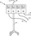
図1は、本発明にかかる、個々の構成要素が機械的及び電気的に結合される、多くのモジュールからなる電子システムを示す正面図である。
図2は、結合前の位置決めされた一対のモジュールを示す正面図である。
図3は、図2に示したモジュールが結合された後の状態を示す図であって、本発明にかかるコネクター及び関連する電子部品を示すために一部を破断した図である。
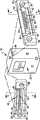
図4は、本発明にかかる結合部品としての一つのモジュールを示す部分拡大分解斜視図である。
図5は、本発明にかかる雌コネクター部を示す、図4の5−5線断面図である。
図6は、本発明にかかる雄コネクター部を示す、図4の6−6線断面図である。
図7は、本発明にかかるコネクターを係合させた状態を示す断面図である。
好適例の説明
まず最初に、図1は、本発明にかかる多くのモジュールからなるシステムを示し、このシステムは参照番号10で示される。この図において、4つの構造モジュール12a乃至12dが結合され、台14に載置されている状態が描かれている。しかし、これにより多数のモジュール12または少数のモジュール12をシステム10に組み込むことも可能である。上記システムには、少なくとも一つの入力16と少なくとも一つの出力18が存在する。
本発明の目的からは、各モジュールの具体的な機能は重要ではない。しかし、このようなモジュールは、個々の性能を発揮させるため、単一方向または双方向に通信可能な電子部品を有するようなものであることが必要である。上述の図示された具体例について説明を続けると、一つのモジュール12、例えば、モジュール12cは、種々の関係する医療用モジュール12a、12b、12d、例えば、大容量非経口ポンプ、注入ポンプ、パルス式酸素濃度計、心電計等の医療用装置を監視し、または制御し、あるいはこれらの両方を行う中央処理装置である。この例において、本発明にかかる装置では、一つのモジュールから次のモジュールへ電気信号を送信することができ、さらには隣接しない他のモジュールへ直接通信できるように結合されているものとする。静脈管理システムは、モジュール間の双方向の通信が必要な場合の一例である。単一方向の通信の例としては、通信が外方向、すなわちスピーカーの方向にしか行われないモジュラーステレオコンポシステムがある。
しかし、本発明の目的からは、すべてのモジュール12a、12b、12c、12dは、本発明にかかる同一のコネクターが設けられているという点において同一と考えられ、このような観点から、それらのモジュールは、機械的及び電気的結合状態を維持するため、いかなる順番またはランダムに機械的及び電気的に結合されることが可能である。
図2は、結合される前の二つのモジュール12a、12bを例示的に示すものである。具体的には、モジュール12bの雄コネクター部22が、モジュール12aの雌コネクター部22への挿入に備えた状態にある。モジュール12bに対するモジュール12aの矢線25の方向(またはモジュール12bの矢線25とは反対の方向)の回転に伴い、これらのモジュールは、図3に示す要領で結合される。図3に示すように、モジュール12a及び12bが機械的に結合されると、モジュール12aの電子部品26もまた電気的にモジュール12bの電子部品26に結合される。これらの機械的及び電気的な結合か同時に行われる具体的な要領は、図4を参照しながら以下に詳細に示される。
さらに、図3を参照して、モジュール12aとモジュール12bの間の結合は、モジュール12aの係止メカニズム28aとモジュール12bの係止メカニズム30bによってより実質的に行うことができる点に留意しなければならない。係止メカニズム28a、30b及び他の動作は、関連技術において公知のメカニズム及び方法によって行うことができることが利点である。
図4に示すように、例示されたモジュール12には、内部電子部品(図3において参照番号26によって示される部品)を囲み、そのハウジングを形成する壁部34によって構成されるケーシング32が設けられる。モジュール12はまた、本発明にかかる二つのコネクター部、すなわち、上述の雄コネクター部22と雌コネクター部24を有する。コネクター部22、24は、プラスチック、または熱可塑性プラスチックが充てんされたガラス等の非導電性材料から、成形及び機械加工等の公知の製造工程によって形成することができる。コネクター部は、ケーシング32の壁部34に、電子部品26に接近し、これに係合されるように形成される係合穴36(その一つのみが図示されている)に受け入れられるのが好ましい。このコネクター部は、その目的のために備えられるねじ穴38を介して備えられたねじによって、例えば、壁部34または、ケーシング32内の内部支持構造に固定される。他の固定手段については、本発明の技術的範囲を逸脱しないで、本発明の属する技術分野における熟練者によって備えることができる。
図4に示すように、雌コネクター部24は、ケーシング32の壁部34を介して、穴(図示しない)の中の、雌コネクター部24とケーシング32との間の破線がケーシングと交差する場所に位置する。図4及び図5を参照すると、雌コネクター部24は略々矩形状の空隙40として形成される。空隙40は、この空隙40を囲み空隙40の端壁を形成する周辺部42によって形成される。外側に延設された上方当接部48及び下方当接部50が、さらに、周辺部42の相対向するそれぞれの部分に設けられる。ねじ穴38は、上述のように固定手段の一例として例示されたものであるが、このねじ穴38は周辺部42に位置する。
少なくとも一つの電気的接触部52の最初の一組が、その中に好適な弾性接触部を形成するため、空隙40に位置決めされる。電気的接触部52によって、雌コネクター部24を介してケーシング32の電子部品26に電気的な結合状態が与えられる。本発明の目的を達成するため、電気的接触部52は、本実施例に示される用途に適したものであれば関係技術分野において公知のものを使用することができる。静脈管理システムに使用するのに適する電気的接触部の一例としては、打ち抜きによって形成されたベリリウム銅接触部がある。電気的接触部52は、以下に述べるように、雄コネクター部22の係合する接触部に対して付勢されることが好ましい。
図4及び図6を参照して説明すると、雄コネクター部22には、基部56を有し外側及び上方へ向かって曲成された唇状部58まで延びる延設部55が設けられる。より具体的に説明すると、曲成された唇状部58が上方に傾斜し、延設部55にフックのような形状を与えている。延設部55の基部56は、周辺部60とともに、それらの間に内側に向かう下方空間62を形成する。上方向への上方開口64が、3つの側部に、実質的に延設部55、基部56及び周辺部60によって形成される。より具体的に説明すると、延設部55の曲成された唇状部58が、部分的に周辺部60を形成する表面65と、コネクター部がその上に置かれたときに略々外側にケーシング32から離れるように向けられる表面66を有する。
雄コネクター部22には、露出接触面69を形成するため、延設部55の表面66を貫通し、その中に埋め込まれる第2の対の電気的接触部68を備えている。雄コネクター部22がケーシング32に固定されると、第2の対の電気的接触部68が穴部36を介して導通し、ケーシング32内に保持された電子部品26と結合される。従って、電子部品26に対して第2の対の電気的接触部68を介して電気的結合が確立される。
本発明にかかる装置が動作する際には、略々図2に示されるように、モジュール12a等のモジュール12が、モジュール12b等のもう一つのモジュール12に相対的に位置する。各モジュールには、多数のモジュールを結合することができるように、雄コネクター部22と雌コネクター部24が相対向する位置に設けられているのが好適である。しかし、2つのモジュールのみを結合する場合には、一方には雌コネクター部24を、他方に雄コネクター部22を設ければ十分である。図2に示すモジュールの位置において、モジュール12bの雄コネクター部22の延設部55(図6)がモジュール12aの雌コネクター部24の空隙40(図5)に挿入するために支持される。それに引き続き、モジュール12aが矢線25に示す方向に回転すると、モジュール12bのコネクターの曲成された唇状部58が、空隙40を介して、モジュール12aの雌コネクター部24に挿入される。(あるいは、その代わりに、モジュール12bが矢線25とは反対方向に回転する。)この挿入によって、モジュール12bの雄コネクター部22の電気的接触部68が、モジュール12aの雌コネクター部24の第1の対の電気的接触部52に対して電気的に結合されるように位置決めされる。最終的に、二つのモジュールの電子部品26が、図7に示すように、電気的に結合されるように位置決めされる。
電気的接触部52、68の間の電気的結合に加えて、雄コネクター部22と雌コネクター部24の間の上述の係合は、また、二つのモジュール12a及び12bを互いに機械的に結合するように機能する。図7に示すように、空隙40を介しての曲成された唇状部58の挿入によって、雌コネクター部24の上方当接部48が雄コネクター部22の上方空間64に位置決めされ、雄コネクター部によって雌コネクター部が鉛直方向に支持される。さらに、雌コネクター部24の上方当接部48が傾斜した唇状部58の背後に位置し、コネクター部が互いに縦方向に離れるのを防止している。空隙40に受け入れられ、端壁41に当接する延設部55によってもまた、コネクター部が互いに側面方向に、すなわち縦方向に分かれるのが防止される。
さらに、雌コネクター部の下方当接部50が下方空隙62に差し込まれるようにして係合する。これによって、基部56を支持する下方当接部50の上面によって、雌コネクター部24が雄コネクター部22を鉛直方向に支持することができる。いずれかのモジュールが他方の重量を支持するように機械的にモジュール12a、12bを結合するため、雄コネクター部22が雌コネクター部24と係合する。これらのモジュールのうちの一つのモジュールの、上述の係合のための回転方向と反対方向の回転のみ、及び重力に対する反力が係合を解くように働く。多重コネクター部が図1乃至図4に示すように、3つ以上のモジュールを結合することができ、側方及び背後のコネクター等の、その他の組み合わせまたは方向付け、あるいはこれらの両方を採用することができることが容易に理解できる。
図7から、延設部55の長さが空隙40の深さよりも短いことが解る。すなわち、コネクター部が結合されると空隙72が形成される。これらの部分のそれぞれの長さ及び深さ、及び空隙40内の電気的接触部52の位置は、雄コネクター部が挿入された場合にのみ電気的接触部52が弾性変形するように選択される。多数使用されることにより、このようにして連続的な好適な電気的結合が確保される。
本実施例において、具体的に、詳細に開示されたコネクターによって、本発明の目的を完全に達成することができ、上述の利点がもたらされるが、上記コネクターは、単に発明の好適例として記載したに過ぎず、本発明は添付の特許請求の範囲に記載された以上の詳細な構成または設計に限定されるものではないことに留意しなければならない。BACKGROUND OF THE INVENTION 1. Field of the Invention The present invention relates generally to mechanical and electrical connectors. More specifically, the present invention couples electronic components held in separate structural modules by mechanically engaging the modules with each other, and at the same time provides an electrical coupling between the components. Related to the mechanism.
2. Description of Related Art Many applications have been filed regarding the techniques required to mechanically and electrically couple electronic components located in remote structural modules. Examples include modular stereo components, portable communication equipment, electronic test equipment and the like. In addition, many other application examples are likely to exist.
A more specific example where each element must be electrically and mechanically coupled is a modern electronic medical system, such as a venous fluid infusion system to a patient.
One strategy for providing a venous fluid infusion system that addresses the rapidly changing and complex modern medical environment is to build a system having separate components with different functions. A significant advantage of such a system is that each element of the system can be selectively incorporated, if necessary, according to the special requirements of the system. For example, U.S. Pat. No. 4,756,706 to Kernset et al. Discloses an invention named "Centrally Controlled Modular Infusion Pump System". However, a problem associated with the modular system disclosed by Colens et al. Is that the medical environment is becoming more complex and demanding, so that the construction and operation of a vein management system is also becoming more complex. As a further example, in U.S. Pat. No. 4,756,706 disclosed by Coln, each element is first coupled to the user, and then each component is electrically connected by another different operation. It is demanding to be combined.
Thus, the present invention allows a mechanical and electrical coupling to be performed simultaneously in a single operation, thereby enabling a vein management system (or a system comprising all analog mechanical / electronic components). This greatly reduces the complexity of assembly. Another advantage is that by reducing the number of parts, the costs for managing the parts and other related costs can also be reduced.
SUMMARY OF THE INVENTION In view of the foregoing, it is an object of the present invention to provide a connector that can mechanically couple spaced structural modules in an electronic system and provide electrical coupling between them. .
Another object of the present invention is to mechanically couple the separated components of such a system and to make electrical coupling so that the mechanical and electrical coupling between the components is substantially equal. It is to provide a connector that can be performed simultaneously by two operations.
Another object of the present invention is to mechanically isolate the separated mechanical components of the electronic system in which the electrical coupling takes place, which is easy to use, relatively simple in structure and advantageous in terms of cost. It is to provide a device for coupling.
These and other objects can be achieved by the present invention relating to mechanical and electrical connectors comprised of first and second removable parts. The first component includes a body portion having an extending portion that extends outward and upward from the body portion. At least one electrical conductor extends through the first component and extends to a contact surface on the outer surface of the extension. The second part is also configured to slidably receive the extension of the first part and has a body cavity with a sized dimension. The extending part of the first part cannot practically move directly in the vertical direction and the vertical direction into the main body gap of the second part. The extending part of the first part rotates upward and downward within the main body gap, thereby preventing the vertical and vertical separation of both parts. The second part is also provided with at least one electrical conductor that extends through the second part to a contact surface located in the body cavity. When the first and second parts come into contact with each other to establish an electrical coupling state between the two conductors, specifically, one of the engaging parts of the first and second parts simultaneously prevents vertical separation. Both engaging parts are configured to support the other side in the vertical direction.
Another aspect of the invention is to provide mechanical and electrical connectors that are integral to the modular system. In this system, the first module has a wall portion that forms a space, and this wall portion forms a space close to the space, and a peripheral portion exists in the space. A first electrical contact is positioned in the space of the first module. The second module also has a wall that forms a space. An extending part having an inclined lip-like part is provided on the wall part of the second module. In order to grasp the periphery of the gap of the first module, the extension portion is determined to be inserted into the gap of the first module through the gap of the wall portion of the first module. This peripheral portion is gripped between the inclined lip portion and the wall portion of the second module when the second module is rotated. A second electrical contact portion is embedded in the extending portion of the wall portion of the second module, and this second electrical contact portion establishes an electrical conduction state between the two modules. 1 Position to be in contact with the electrical contact. In addition, this arrangement makes it possible to obtain an engaged state and a non-engaged state only by appropriate rotation, and it is possible for one of the modules to mechanically support the other module.
Furthermore, as an aspect of the present invention, it is possible to combine many modules as described above.
[Brief description of the drawings]
FIG. 1 is a front view showing an electronic system composed of a number of modules in which individual components are mechanically and electrically coupled according to the present invention.
FIG. 2 is a front view showing a pair of positioned modules before joining.
FIG. 3 is a view showing a state after the modules shown in FIG. 2 are joined, and is a partially cutaway view showing the connector and related electronic components according to the present invention.
FIG. 4 is a partially enlarged exploded perspective view showing one module as a connecting part according to the present invention.
5 is a cross-sectional view taken along line 5-5 of FIG. 4, showing a female connector portion according to the present invention.
6 is a cross-sectional view taken along line 6-6 of FIG. 4, showing a male connector portion according to the present invention.
FIG. 7 is a sectional view showing a state in which the connector according to the present invention is engaged.
DESCRIPTION OF THE PREFERRED EMBODIMENT First of all, FIG. 1 shows a system consisting of a number of modules according to the invention, this system being denoted by
For the purposes of the present invention, the specific function of each module is not important. However, such modules need to have electronic components that can communicate in a single direction or in both directions in order to achieve individual performance. Continuing with the illustrated embodiment described above, a
However, for the purposes of the present invention, all
FIG. 2 exemplarily shows the two
Further, referring to FIG. 3, it should be noted that the coupling between
As shown in FIG. 4, the illustrated
As shown in FIG. 4, the
An initial set of at least one
Referring to FIGS. 4 and 6, the
The
When the apparatus according to the present invention operates, the
In addition to the electrical coupling between the
Further, the
From FIG. 7, it can be seen that the length of the extended
In this embodiment, the connector disclosed in detail can achieve the object of the present invention completely and provide the above-mentioned advantages, but the connector is described only as a preferred embodiment of the invention. It should be noted, however, that the present invention is not limited to the detailed arrangements or designs described above in the appended claims.
Claims (2)
Translated fromJapanese前記第1部品を通って前記フック状の延設部の外面上の接触面まで延びる少なくとも一つの電気的導体を設け、
本体空隙を有する胴部を有する脱着可能な第2部品を設け、該本体空隙は、下方に向かう部分と前記第2部品の前記胴部の延設部を含む下方壁部によって形成され、前記下側に延びる部分が前記第1部品の前記上方に向かう開口に係合し、前記第2部品の前記延設部が前記第1部品の前記内側に向かう空間に受け入れられ、前記両部分間の接触によって前記第1部品の前記第2部品に対する横方向または鉛直方向への動きが維持されるように、外側及び上方に前記空隙に向かって回転したときに、前記第1部品の前記フック状の延設部を摺動して受けるように前記本体空隙が構成されるとともに、その寸法が決定され、
前記第2部品を通って前記本体空隙内に位置する接触面まで延設される少なくとも一つの電気的導体を設け、前記電気的導体は、前記両導体間に電気的接触状態を提供するため、前記空隙に受け入れられたときに、前記第1部品の前記接触面と接触し、前記第1部品の前記フック状の延設部によって弾性変形することを特徴とする電気的及び機械的コネクター。Providing a first part having a body part, the body part having a hook-like portion extending from the body part toward the outside and at a certain angle along the edge part extending upwardobliquely upward; An upward opening is formed between the edge portion and the body portion of the first part, and the body portion forms an inward space below the hook-shaped extending portion of the first part. ,
Providing at least one electrical conductor extending through the first part to a contact surface on an outer surface of the hook-like extension;
A detachable second part having a body having a body gap is provided, the body gap being formed by a downward wall and a lower wall including an extension of the body of the second part, and A side extending portion engages with the upward opening of the first part, and the extended portion of the second part is received in the space toward the inside of the first part, and the contact between the two parts The hook-like extension of the first part when rotated outwardly and upwardly toward the gap such that the movement of the first part in the lateral or vertical direction relative to the second part is maintained. The main body gap is configured to slide and receive the installation portion, and its dimensions are determined,
Providing at least one electrical conductor extending through the second part to a contact surface located in the body cavity, the electrical conductor providing electrical contact between the two conductors; When received in the gap, the electrical and mechanical connector is in contact with the contact surface of the first component and elastically deformed by the hook-shaped extending portion of the first component.
Applications Claiming Priority (3)
| Application Number | Priority Date | Filing Date | Title |
|---|---|---|---|
| US403,502 | 1995-03-13 | ||
| US08/403,502US5601445A (en) | 1995-03-13 | 1995-03-13 | Electrical and structural interconnector |
| PCT/US1996/001662WO1996028858A1 (en) | 1995-03-13 | 1996-02-08 | Electrical and structural interconnector |
Publications (2)
| Publication Number | Publication Date |
|---|---|
| JPH11503555A JPH11503555A (en) | 1999-03-26 |
| JP3848367B2true JP3848367B2 (en) | 2006-11-22 |
Family
ID=23596017
Family Applications (1)
| Application Number | Title | Priority Date | Filing Date |
|---|---|---|---|
| JP52758396AExpired - Fee RelatedJP3848367B2 (en) | 1995-03-13 | 1996-02-08 | Electrical and mechanical connectors |
Country Status (6)
| Country | Link |
|---|---|
| US (1) | US5601445A (en) |
| EP (1) | EP0871989B1 (en) |
| JP (1) | JP3848367B2 (en) |
| AU (1) | AU693662B2 (en) |
| DE (1) | DE69628327T2 (en) |
| WO (1) | WO1996028858A1 (en) |
Families Citing this family (54)
| Publication number | Priority date | Publication date | Assignee | Title |
|---|---|---|---|---|
| US5941846A (en)* | 1995-03-13 | 1999-08-24 | Alaris Medical Systems, Inc. | Method and apparatus for power connection in a modular patient care system |
| US5718562A (en)* | 1995-11-02 | 1998-02-17 | Abbott Laboratories | Interface module for use with an NCT-based pumping mechanism and NCT-based cassette |
| US5772459A (en)* | 1996-03-15 | 1998-06-30 | Delaware Capital Formation, Inc. | Rotationally actuated compliant electrical connector |
| DE19704437C2 (en)* | 1997-02-06 | 1999-06-10 | Neutrik Ag | Electrical connector for electrical lines |
| SE523162C2 (en)* | 2000-01-25 | 2004-03-30 | Aneo Ab | Arrangements for granting a living being an anesthetic condition |
| US6348777B1 (en)* | 2000-02-29 | 2002-02-19 | Alaris Medical Systems, Inc. | Power management system |
| US9600633B2 (en) | 2000-05-18 | 2017-03-21 | Carefusion 303, Inc. | Distributed remote asset and medication management drug delivery system |
| US10353856B2 (en) | 2011-03-17 | 2019-07-16 | Carefusion 303, Inc. | Scalable communication system |
| US11087873B2 (en) | 2000-05-18 | 2021-08-10 | Carefusion 303, Inc. | Context-aware healthcare notification system |
| US20050171815A1 (en)* | 2003-12-31 | 2005-08-04 | Vanderveen Timothy W. | Centralized medication management system |
| US9741001B2 (en) | 2000-05-18 | 2017-08-22 | Carefusion 303, Inc. | Predictive medication safety |
| US9427520B2 (en) | 2005-02-11 | 2016-08-30 | Carefusion 303, Inc. | Management of pending medication orders |
| US10062457B2 (en) | 2012-07-26 | 2018-08-28 | Carefusion 303, Inc. | Predictive notifications for adverse patient events |
| US7860583B2 (en) | 2004-08-25 | 2010-12-28 | Carefusion 303, Inc. | System and method for dynamically adjusting patient therapy |
| US9069887B2 (en) | 2000-05-18 | 2015-06-30 | Carefusion 303, Inc. | Patient-specific medication management system |
| US20040172283A1 (en)* | 2003-02-09 | 2004-09-02 | Vanderveen Timothy W. | Medication management and event logger and analysis system |
| DE10134885B4 (en) | 2001-07-18 | 2004-02-05 | Roche Diagnostics Gmbh | Modular analysis system |
| US8775196B2 (en) | 2002-01-29 | 2014-07-08 | Baxter International Inc. | System and method for notification and escalation of medical data |
| US10173008B2 (en) | 2002-01-29 | 2019-01-08 | Baxter International Inc. | System and method for communicating with a dialysis machine through a network |
| US8234128B2 (en) | 2002-04-30 | 2012-07-31 | Baxter International, Inc. | System and method for verifying medical device operational parameters |
| US20040172300A1 (en)* | 2002-04-30 | 2004-09-02 | Mihai Dan M. | Method and system for integrating data flows |
| US20050065817A1 (en)* | 2002-04-30 | 2005-03-24 | Mihai Dan M. | Separation of validated information and functions in a healthcare system |
| US20040167804A1 (en)* | 2002-04-30 | 2004-08-26 | Simpson Thomas L.C. | Medical data communication notification and messaging system and method |
| US20040172301A1 (en)* | 2002-04-30 | 2004-09-02 | Mihai Dan M. | Remote multi-purpose user interface for a healthcare system |
| US7896572B2 (en)* | 2003-10-30 | 2011-03-01 | Hospira, Inc. | Medical device system |
| US8057679B2 (en) | 2008-07-09 | 2011-11-15 | Baxter International Inc. | Dialysis system having trending and alert generation |
| US10089443B2 (en) | 2012-05-15 | 2018-10-02 | Baxter International Inc. | Home medical device systems and methods for therapy prescription and tracking, servicing and inventory |
| US8554579B2 (en) | 2008-10-13 | 2013-10-08 | Fht, Inc. | Management, reporting and benchmarking of medication preparation |
| US9669226B2 (en) | 2010-09-07 | 2017-06-06 | Empi, Inc. | Methods and systems for reducing interference in stimulation treatment |
| KR20210068610A (en) | 2012-08-31 | 2021-06-09 | 백스터 코포레이션 잉글우드 | Medication requisition fulfillment system and method |
| KR101623326B1 (en) | 2012-10-26 | 2016-05-20 | 백스터 코포레이션 잉글우드 | Improved work station for medical dose preparation system |
| KR101974258B1 (en) | 2012-10-26 | 2019-04-30 | 백스터 코포레이션 잉글우드 | Improved image acquisition for medical dose preparation system |
| US10430554B2 (en) | 2013-05-23 | 2019-10-01 | Carefusion 303, Inc. | Medication preparation queue |
| WO2014190200A1 (en) | 2013-05-22 | 2014-11-27 | Carefusion 303, Inc. | Medication workflow management |
| US11182728B2 (en) | 2013-01-30 | 2021-11-23 | Carefusion 303, Inc. | Medication workflow management |
| EP2973370A4 (en) | 2013-03-13 | 2016-08-17 | Carefusion 303 Inc | PREDICTIVE MEDICATION SECURITY |
| JP6660288B2 (en) | 2013-03-13 | 2020-03-11 | ケアフュージョン 303、インコーポレイテッド | Patient-specific medication management system |
| US20150133861A1 (en) | 2013-11-11 | 2015-05-14 | Kevin P. McLennan | Thermal management system and method for medical devices |
| EP3826028B1 (en) | 2014-06-30 | 2024-04-24 | Baxter Corporation Englewood | Managed medical information exchange |
| US10143795B2 (en) | 2014-08-18 | 2018-12-04 | Icu Medical, Inc. | Intravenous pole integrated power, control, and communication system and method for an infusion pump |
| US11107574B2 (en) | 2014-09-30 | 2021-08-31 | Baxter Corporation Englewood | Management of medication preparation with formulary management |
| US11575673B2 (en) | 2014-09-30 | 2023-02-07 | Baxter Corporation Englewood | Central user management in a distributed healthcare information management system |
| EP3210183B1 (en) | 2014-10-24 | 2020-09-02 | Baxter Corporation Englewood | Automated exchange of healthcare information for fulfillment of medication doses |
| EP3937116A1 (en) | 2014-12-05 | 2022-01-12 | Baxter Corporation Englewood | Dose preparation data analytics |
| CA2978455A1 (en) | 2015-03-03 | 2016-09-09 | Baxter Corporation Englewood | Pharmacy workflow management with integrated alerts |
| NZ737340A (en) | 2015-05-26 | 2019-06-28 | Icu Medical Inc | Disposable infusion fluid delivery device for programmable large volume drug delivery |
| WO2016207206A1 (en) | 2015-06-25 | 2016-12-29 | Gambro Lundia Ab | Medical device system and method having a distributed database |
| WO2017060260A1 (en)* | 2015-10-09 | 2017-04-13 | Fresenius Vial Sas | Rack module and rack |
| AU2017381172A1 (en) | 2016-12-21 | 2019-06-13 | Gambro Lundia Ab | Medical device system including information technology infrastructure having secure cluster domain supporting external domain |
| WO2019161033A1 (en)* | 2018-02-16 | 2019-08-22 | Carefusion 303, Inc. | Module connectors for infusion pump systems |
| US11510720B2 (en)* | 2018-09-07 | 2022-11-29 | Cilag Gmbh International | Managing simultaneous monopolar outputs using duty cycle and synchronization |
| CA3128520A1 (en)* | 2019-02-26 | 2020-09-03 | Conmed Corporation | Modular docking system for electrosurgical equipment |
| USD939079S1 (en) | 2019-08-22 | 2021-12-21 | Icu Medical, Inc. | Infusion pump |
| USD1052728S1 (en) | 2021-11-12 | 2024-11-26 | Icu Medical, Inc. | Medical fluid infusion pump |
Family Cites Families (17)
| Publication number | Priority date | Publication date | Assignee | Title |
|---|---|---|---|---|
| US1482833A (en)* | 1919-06-07 | 1924-02-05 | Ohio Brass Co | Electric coupler |
| US2253971A (en)* | 1940-03-09 | 1941-08-26 | Gen Electric | Food storage receptacle |
| US2369860A (en)* | 1942-05-21 | 1945-02-20 | Yale & Towne Mfg Co | Electric connector |
| US3969796A (en)* | 1975-09-17 | 1976-07-20 | General Electric Company | Releasable fastening arrangement for a radio housing and a battery housing |
| US4316304A (en)* | 1980-09-04 | 1982-02-23 | Parise & Sons, Inc. | Double disconnect, waterproof electrical connector assembly for electrified vacuum hose for wet/dry vacuum cleaner |
| US4756706A (en)* | 1985-01-23 | 1988-07-12 | American Hospital Supply Corporation | Centrally managed modular infusion pump system |
| GB8525339D0 (en)* | 1985-10-15 | 1985-11-20 | Pag Ltd | Battery connector |
| US4906205A (en)* | 1988-10-31 | 1990-03-06 | Stephen C. Burgess | Jumper cable safety means |
| US5145398A (en)* | 1989-09-06 | 1992-09-08 | Amp Incorporated | Turning insertion type electrical connector system |
| US5133680A (en)* | 1990-09-18 | 1992-07-28 | Hewlett-Packard Company | Slotless female contact |
| ES2142793T3 (en)* | 1991-08-08 | 2000-05-01 | Siemens Ag | BUS THAT FORMS AUTOMATICALLY. |
| KR100246214B1 (en)* | 1991-11-18 | 2000-03-15 | 이데이 노부유끼 | Connecting device that can connect casing easily for electrical apparatus |
| US5302136A (en)* | 1992-11-23 | 1994-04-12 | Modicon, Inc. | Apparatus for positively preventing misengagement of multipoint connector elements |
| US5398162A (en)* | 1992-11-27 | 1995-03-14 | At&T Corp. | Circuit module with catch and release for displacing a cantilevered latch |
| TW243558B (en)* | 1993-03-23 | 1995-03-21 | Whitaker Corp | |
| US5417595A (en)* | 1993-04-22 | 1995-05-23 | Applied Robotics, Inc. | Method and apparatus for frequently connecting and disconnecting signal cables |
| US5378169A (en)* | 1993-09-24 | 1995-01-03 | The Whitaker Corporation | Pivotal connector for planar electronic devices |
- 1995
- 1995-03-13USUS08/403,502patent/US5601445A/ennot_activeExpired - Lifetime
- 1996
- 1996-02-08EPEP96905402Apatent/EP0871989B1/ennot_activeExpired - Lifetime
- 1996-02-08JPJP52758396Apatent/JP3848367B2/ennot_activeExpired - Fee Related
- 1996-02-08AUAU49173/96Apatent/AU693662B2/ennot_activeExpired
- 1996-02-08DEDE69628327Tpatent/DE69628327T2/ennot_activeExpired - Lifetime
- 1996-02-08WOPCT/US1996/001662patent/WO1996028858A1/enactiveIP Right Grant
Also Published As
| Publication number | Publication date |
|---|---|
| AU4917396A (en) | 1996-10-02 |
| EP0871989A1 (en) | 1998-10-21 |
| DE69628327T2 (en) | 2004-02-19 |
| WO1996028858A1 (en) | 1996-09-19 |
| US5601445A (en) | 1997-02-11 |
| DE69628327D1 (en) | 2003-06-26 |
| EP0871989A4 (en) | 1999-03-03 |
| JPH11503555A (en) | 1999-03-26 |
| EP0871989B1 (en) | 2003-05-21 |
| AU693662B2 (en) | 1998-07-02 |
Similar Documents
| Publication | Publication Date | Title |
|---|---|---|
| JP3848367B2 (en) | Electrical and mechanical connectors | |
| US5218519A (en) | Card cage system | |
| US6796717B2 (en) | Angular mounted optical connector adaptor frame | |
| US11631949B2 (en) | Magnetic connector assembly | |
| US6213815B1 (en) | Multimedia electric adapter | |
| US4477862A (en) | Backplane connector | |
| US9004951B2 (en) | Multi-functional transfer connector for connecting with different receptacles | |
| WO1996028858A9 (en) | Electrical and structural interconnector | |
| EP2087560B1 (en) | Miniature circular connector system | |
| US6454603B2 (en) | Shielded connector with integral latching and ground structure | |
| US7500880B1 (en) | Connector for telecommunication devices | |
| US6137679A (en) | Multi-bus mobile hard disk drive rack | |
| JP3194975U (en) | High density rectangular interconnect | |
| KR940003121A (en) | Electrical connector | |
| JP2011502435A (en) | Modular power line adapter and method of use | |
| TW201021311A (en) | Modular electrical connector with opposing contact support members | |
| JP2627908B2 (en) | Receptacle assembly for LAN outlet and data connector used therefor | |
| US20040132342A1 (en) | Multilayer electric connector | |
| EP0866520A2 (en) | Electrical ribbon wire connectors | |
| EP3707785A1 (en) | Kvm extension device self-contained within a video connector | |
| CA2215305C (en) | Electrical and structural interconnector | |
| CN109510017A (en) | terminal module and electric connector thereof | |
| WO2004017466A3 (en) | A plate locking system for mated electrical connectors and methods thereof | |
| CN208904323U (en) | Male end connector | |
| US6764331B2 (en) | Small-sized connector |
Legal Events
| Date | Code | Title | Description |
|---|---|---|---|
| A711 | Notification of change in applicant | Free format text:JAPANESE INTERMEDIATE CODE: A712 Effective date:20040615 | |
| A131 | Notification of reasons for refusal | Free format text:JAPANESE INTERMEDIATE CODE: A131 Effective date:20050628 | |
| A601 | Written request for extension of time | Free format text:JAPANESE INTERMEDIATE CODE: A601 Effective date:20050921 | |
| A602 | Written permission of extension of time | Free format text:JAPANESE INTERMEDIATE CODE: A602 Effective date:20051107 | |
| A521 | Request for written amendment filed | Free format text:JAPANESE INTERMEDIATE CODE: A523 Effective date:20051227 | |
| A131 | Notification of reasons for refusal | Free format text:JAPANESE INTERMEDIATE CODE: A131 Effective date:20060228 | |
| A72 | Notification of change in name of applicant | Free format text:JAPANESE INTERMEDIATE CODE: A721 Effective date:20060209 | |
| A521 | Request for written amendment filed | Free format text:JAPANESE INTERMEDIATE CODE: A523 Effective date:20060531 | |
| TRDD | Decision of grant or rejection written | ||
| A01 | Written decision to grant a patent or to grant a registration (utility model) | Free format text:JAPANESE INTERMEDIATE CODE: A01 Effective date:20060801 | |
| A61 | First payment of annual fees (during grant procedure) | Free format text:JAPANESE INTERMEDIATE CODE: A61 Effective date:20060825 | |
| R150 | Certificate of patent or registration of utility model | Free format text:JAPANESE INTERMEDIATE CODE: R150 | |
| FPAY | Renewal fee payment (event date is renewal date of database) | Free format text:PAYMENT UNTIL: 20100901 Year of fee payment:4 | |
| FPAY | Renewal fee payment (event date is renewal date of database) | Free format text:PAYMENT UNTIL: 20100901 Year of fee payment:4 | |
| S531 | Written request for registration of change of domicile | Free format text:JAPANESE INTERMEDIATE CODE: R313531 | |
| S533 | Written request for registration of change of name | Free format text:JAPANESE INTERMEDIATE CODE: R313533 | |
| FPAY | Renewal fee payment (event date is renewal date of database) | Free format text:PAYMENT UNTIL: 20100901 Year of fee payment:4 | |
| R350 | Written notification of registration of transfer | Free format text:JAPANESE INTERMEDIATE CODE: R350 | |
| FPAY | Renewal fee payment (event date is renewal date of database) | Free format text:PAYMENT UNTIL: 20110901 Year of fee payment:5 | |
| FPAY | Renewal fee payment (event date is renewal date of database) | Free format text:PAYMENT UNTIL: 20120901 Year of fee payment:6 | |
| FPAY | Renewal fee payment (event date is renewal date of database) | Free format text:PAYMENT UNTIL: 20130901 Year of fee payment:7 | |
| R250 | Receipt of annual fees | Free format text:JAPANESE INTERMEDIATE CODE: R250 | |
| LAPS | Cancellation because of no payment of annual fees |