JP3847753B2 - Image processing apparatus, image processing method, recording medium, computer program, semiconductor device - Google Patents
Image processing apparatus, image processing method, recording medium, computer program, semiconductor deviceDownload PDFInfo
- Publication number
- JP3847753B2 JP3847753B2JP2004023013AJP2004023013AJP3847753B2JP 3847753 B2JP3847753 B2JP 3847753B2JP 2004023013 AJP2004023013 AJP 2004023013AJP 2004023013 AJP2004023013 AJP 2004023013AJP 3847753 B2JP3847753 B2JP 3847753B2
- Authority
- JP
- Japan
- Prior art keywords
- image
- operator
- images
- candidate
- moving image
- Prior art date
- Legal status (The legal status is an assumption and is not a legal conclusion. Google has not performed a legal analysis and makes no representation as to the accuracy of the status listed.)
- Expired - Fee Related
Links
Images


Classifications
- G—PHYSICS
- G06—COMPUTING OR CALCULATING; COUNTING
- G06F—ELECTRIC DIGITAL DATA PROCESSING
- G06F3/00—Input arrangements for transferring data to be processed into a form capable of being handled by the computer; Output arrangements for transferring data from processing unit to output unit, e.g. interface arrangements
- G06F3/01—Input arrangements or combined input and output arrangements for interaction between user and computer
- G06F3/017—Gesture based interaction, e.g. based on a set of recognized hand gestures
- G—PHYSICS
- G06—COMPUTING OR CALCULATING; COUNTING
- G06F—ELECTRIC DIGITAL DATA PROCESSING
- G06F3/00—Input arrangements for transferring data to be processed into a form capable of being handled by the computer; Output arrangements for transferring data from processing unit to output unit, e.g. interface arrangements
- G06F3/01—Input arrangements or combined input and output arrangements for interaction between user and computer
- G06F3/011—Arrangements for interaction with the human body, e.g. for user immersion in virtual reality
- G06F3/012—Head tracking input arrangements
- G—PHYSICS
- G06—COMPUTING OR CALCULATING; COUNTING
- G06F—ELECTRIC DIGITAL DATA PROCESSING
- G06F3/00—Input arrangements for transferring data to be processed into a form capable of being handled by the computer; Output arrangements for transferring data from processing unit to output unit, e.g. interface arrangements
- G06F3/01—Input arrangements or combined input and output arrangements for interaction between user and computer
- G06F3/048—Interaction techniques based on graphical user interfaces [GUI]
- G06F3/0481—Interaction techniques based on graphical user interfaces [GUI] based on specific properties of the displayed interaction object or a metaphor-based environment, e.g. interaction with desktop elements like windows or icons, or assisted by a cursor's changing behaviour or appearance
- G06F3/0482—Interaction with lists of selectable items, e.g. menus
Landscapes
- Engineering & Computer Science (AREA)
- General Engineering & Computer Science (AREA)
- Theoretical Computer Science (AREA)
- Human Computer Interaction (AREA)
- Physics & Mathematics (AREA)
- General Physics & Mathematics (AREA)
- User Interface Of Digital Computer (AREA)
- Image Processing (AREA)
- Image Analysis (AREA)
- Processing Or Creating Images (AREA)
Description
Translated fromJapanese本発明は、ビデオカメラなどの撮影装置により撮影された撮影画像を、コマンド等の入力インタフェースとして利用するための画像処理技術に関する。 The present invention relates to an image processing technique for using a photographed image photographed by a photographing device such as a video camera as an input interface for a command or the like.
コンピュータ、ビデオゲーム機などによく用いられる入力装置として、キーボード、マウス、コントローラ等がある。操作者は、これらの入力装置を操作することにより所望のコマンドを入力して、入力されたコマンドに応じた処理をコンピュータ等に行わせる。そして操作者は、処理結果として得られた画像、音などを、ディスプレイ装置やスピーカにより視聴する。操作者は、入力装置に備えられる多くのボタンを操作したり、ディスプレイ装置に表示されたカーソルなどを見ながら操作することにより、コマンドの入力を行うこととなる。 As an input device often used for a computer, a video game machine, etc., there are a keyboard, a mouse, a controller, and the like. The operator inputs a desired command by operating these input devices, and causes a computer or the like to perform processing according to the input command. Then, the operator views the image, sound, etc. obtained as a processing result through a display device or a speaker. The operator inputs commands by operating many buttons provided on the input device or by operating while viewing a cursor displayed on the display device.
最近は、上記のような従来からの入力装置を用いる方法の他に、ビデオカメラ等の撮影装置を用いて撮影した動画像により、コマンドの入力を可能にした技術も開発されている。本出願人も、特開2002−196855号公報(発明の名称:画像処理装置、画像処理方法、記録媒体、コンピュータプログラム、半導体デバイス)において、操作者の動画像を取り込んで、操作者の動画像と当該動画像により操作されるオブジェクト画像とを合成して所定のディスプレイ装置に表示させる技術を開示している。動画像の動きに応じてオブジェクト画像が操作されるために、動画像自体が入力インタフェースとして機能することになる。 Recently, in addition to the conventional method using an input device as described above, a technique has been developed that allows a command to be input using a moving image shot using a shooting device such as a video camera. The present applicant also captures the moving image of the operator in Japanese Patent Laid-Open No. 2002-196855 (name of the invention: image processing apparatus, image processing method, recording medium, computer program, semiconductor device), and moves the moving image of the operator. And an object image operated by the moving image are displayed and displayed on a predetermined display device. Since the object image is operated according to the motion of the moving image, the moving image itself functions as an input interface.
このように動画像を入力インタフェースとして用いる場合、操作者が適切な位置に表示されるように撮影装置のアングルを調整したり、画角を選択することは、正確な操作のために極めて重要である。そのために、初期設定が煩雑、複雑になりがちである。設定が不十分であったり、操作者が適切な位置にいない場合には、オブジェクト画像を操作困難な位置に操作者の動画像が表示されたり、或いは誤認識の原因となり、正確な入力動作の妨げになることもある。 When using a moving image as an input interface in this way, it is extremely important for an accurate operation to adjust the angle of the photographing device and select the angle of view so that the operator can display it at an appropriate position. is there. Therefore, the initial setting tends to be complicated and complicated. If the setting is insufficient or the operator is not in the proper position, the moving image of the operator may be displayed at a position where it is difficult to operate the object image, or it may cause a recognition error, resulting in an accurate input operation. It can be an obstacle.
本発明は、上記のような問題を解決するものであり、動画像を入力インタフェースとして用いた場合の初期設定を容易に行うための画像処理技術を提供することを課題とする。
The present invention solves the above-described problems, and an object of the present invention is to provide an image processing technique for easily performing initial setting when a moving image is used as an input interface.
以上の課題を解決する本発明の画像処理装置は、所定のイベントに関連づけされたオブジェクトについてのオブジェクト画像を生成するオブジェクト画像生成手段と、操作者の画像をその一部に含んだ鏡面動画像に前記オブジェクト画像を合成して合成画像を生成する画像合成手段を有し、この合成画像を所定のディスプレイ装置に表示させる画像処理装置であって、前記鏡面動画像に含まれる前記操作者の画像の位置を検出する検出手段を備え、前記画像合成手段は、前記検出手段により検出された前記操作者の画像の位置に応じて、前記操作者の手の画像が届く領域に前記オブジェクト画像が表示されるように、前記オブジェクト画像と前記鏡面動画像とを合成するように構成されている。
操作者の画像の位置に合わせて、操作者の手の画像が届く領域にオブジェクト画像が表示されるために、操作者が操作不能な位置にオブジェクト画像が表示されることがなくなる。そのために、煩雑な初期設定を行わなくても、動画像を入力インタフェースとして容易にしようできるようになる。An image processing apparatus according to the present invention that solves the above-described problems includes an object image generation unit that generates an object image for an object associated with a predetermined event, and a specular moving image that includes an operator image as a part thereof. An image processing unit that combines the object images to generate a composite image, and displays the composite image on a predetermined display device, the image processing device including an image of the operator included in the specular moving image; Detection means for detecting a position, wherein the image composition means displays the object image in a region where the image of the operator's hand reaches according to the position of the operator's image detected by the detection means. As described above, the object image and the specular moving image are combined.
Since the object image is displayed in an area where the image of the operator's hand reaches in accordance with the position of the operator's image, the object image is not displayed at a position where the operator cannot operate. Therefore, a moving image can be easily used as an input interface without performing complicated initial settings.
鏡面動画像は動画像を撮影する撮影装置側で生成するようにしてもよいが、例えば、本発明の画像処理装置が、所定の撮影装置により撮影された前記操作者の画像をその一部に含む動画像を、この撮影装置から取り込む画像取込手段と、取り込んだ動画像に鏡面処理を施して前記鏡面動画像を生成する画像反転手段と、をさらに備えるようにすれば、汎用の撮影装置で鏡面動画像を得ることができるようになる。 The specular moving image may be generated on the side of the image capturing device that captures the moving image. For example, the image processing device of the present invention uses the image of the operator captured by a predetermined image capturing device as a part thereof. A general-purpose imaging device is further provided with an image capturing unit that captures a moving image including the image from the imaging device, and an image reversing unit that performs mirror processing on the captured moving image to generate the mirrored moving image. With this, it is possible to obtain a mirror moving image.
操作者の手の画像が届く領域とは、例えば操作者の顔の位置の周辺部分とすることができる。顔の位置の周辺部分にオブジェクト画像を表示させる場合には、例えば、前記検出手段が、前記操作者の画像から当該操作者の顔の位置を検出するように構成され、前記画像合成手段が、検出された顔の位置に応じた領域に前記オブジェクト画像が表示されるように、前記オブジェクト画像と前記鏡面動画像とを合成するように構成される。この場合、前記画像合成手段は、前記検出手段により検出された前記操作者の画像の位置に、当該操作者が検出されたことを示すマーカを表す画像を合成するように構成されていてもよい。 The region where the image of the operator's hand can reach can be, for example, a peripheral portion of the position of the operator's face. In the case of displaying an object image in the peripheral portion of the face position, for example, the detection means is configured to detect the position of the operator's face from the operator's image, and the image composition means The object image and the specular moving image are combined so that the object image is displayed in an area corresponding to the detected face position. In this case, the image synthesizing unit may be configured to synthesize an image representing a marker indicating that the operator has been detected at the position of the operator's image detected by the detecting unit. .
前記検出手段は、操作者の画像の位置の他に前記操作者の画像の大きさを検出するように構成されていてもよい。この場合、前記画像合成手段が、検出された前記操作者の画像の大きさに応じた大きさに前記オブジェクト画像が表示されるように、前記オブジェクト画像と前記鏡面動画像とを合成するように構成される。これにより、操作者の画像の大きさに応じた大きさでオブジェクト画像を表示できるようになり、操作者の画像とオブジェクトの画像とがアンバランスに表示されることはない。 The detection means may be configured to detect the size of the operator's image in addition to the position of the operator's image. In this case, the image synthesizing unit synthesizes the object image and the specular moving image so that the object image is displayed in a size corresponding to the size of the detected image of the operator. Composed. As a result, the object image can be displayed in a size corresponding to the size of the operator's image, and the operator's image and the object image are not displayed unbalanced.
前記鏡面動画像のフレーム間の画像の差異を表す差分画像を、複数重ねた動き画像マップを生成する手段をさらに備える場合には、前記画像合成手段は、この動き画像マップにより得られる前記操作者の画像の動きに応じて、前記オブジェクト画像を合成する領域を決めるように構成されていてもよい。
また、前記鏡面動画像のフレーム間で各領域の色の変化を検出する手段を備える場合には、前記画像合成手段は、この色の変化でにより得られる前記操作者の画像の動きに応じて、前記オブジェクト画像を合成する領域を決めるように構成されていてもよい。In the case of further comprising means for generating a motion image map in which a plurality of difference images representing image differences between frames of the specular moving image are superimposed, the image composition means is configured to obtain the operator obtained from the motion image map. The area for combining the object images may be determined in accordance with the movement of the image.
Further, in the case where a means for detecting a color change of each region between the frames of the mirrored moving image is provided, the image composition means is responsive to the movement of the operator's image obtained by the color change. The area for combining the object images may be determined.
操作者になり得る複数の操作者候補の画像が前記鏡面動画像に含まれている場合には、前記検出手段は、複数の前記操作者候補のそれぞれについて操作者候補の画像の位置を検出するように構成され、前記画像合成手段は、前記検出手段により検出された複数の前記操作者候補の画像の各々に位置に応じて、前記オブジェクト画像が複数の操作者候補の手の画像が届く範囲に表示されるように、前記オブジェクト画像と前記鏡面動画像とを合成するように構成されていてもよい。
つまり各操作者候補の画像がオブジェクト画像を操作できるような位置に、オブジェクト画像が合成される。例えば、操作者候補が2人の場合にはその間にオブジェクト画像が表示されるように合成される。In a case where images of a plurality of operator candidates that can be operators are included in the mirror moving image, the detection unit detects the positions of the operator candidate images for each of the plurality of operator candidates. The image composition unit is configured such that the object image reaches a plurality of operator candidate hand images according to the position of each of the plurality of operator candidate images detected by the detection unit. The object image and the specular moving image may be combined so as to be displayed on the screen.
That is, the object image is synthesized at a position where each operator candidate image can operate the object image. For example, when there are two operator candidates, they are combined so that an object image is displayed between them.
複数の操作者候補から操作者を選ぶ場合には、以下のような構成となる。
例えば、前記オブジェクト画像が操作された場合に、当該オブジェクト画像を操作した操作者候補の画像を前記操作者の画像に選択する手段を備えるようにする。オブジェクトを最初に操作した操作者候補が操作者になる。
他に、前記鏡面動画像が複数の異なる角度から同時に撮影されたステレオ画像である場合には、ステレオ画像を構成する複数の画像のそれぞれで前記オブジェクト画像に最も近い位置に表示される操作者候補の画像を前記操作者の画像に選択する手段を備えるようにする。オブジェクト画像に最も近い位置に表示される操作者候補が操作者になる。
他に、前記オブジェクト画像生成手段を、操作者候補の各々に対応して複数のオブジェクト画像を生成するように構成して、前記画像合成手段は、各操作者候補の画像に対して、対応するオブジェクト画像を当該操作者候補の手の画像が届く範囲に表示されるように、前記複数のオブジェクト画像と前記鏡面動画像とを合成するように構成してもよい。この場合、複数のオブジェクト画像のいずれか一つが操作された場合に、当該オブジェクト画像に対応する操作者候補の画像を前記操作者の画像に選択する。最初に、自分に割り当てられたオブジェクト画像を操作した者が操作者となる。When an operator is selected from a plurality of operator candidates, the configuration is as follows.
For example, when the object image is operated, means for selecting an image of an operator candidate who has operated the object image as the image of the operator is provided. The operator candidate who operated the object first becomes the operator.
In addition, when the specular moving image is a stereo image taken simultaneously from a plurality of different angles, the operator candidate displayed at the position closest to the object image in each of the plurality of images constituting the stereo image Means for selecting the image of the operator as the image of the operator. The operator candidate displayed at the position closest to the object image becomes the operator.
In addition, the object image generation means is configured to generate a plurality of object images corresponding to each of the operator candidates, and the image composition means corresponds to each operator candidate image. The plurality of object images and the specular moving image may be combined so that the object images are displayed in a range where the image of the operator candidate's hand can reach. In this case, when any one of the plurality of object images is operated, an operator candidate image corresponding to the object image is selected as the operator image. First, the person who operates the object image assigned to him / her becomes the operator.
複数の操作者候補から操作者が選ばれると、前記表示制御手段は、デジタル処理又は前記鏡面動画像を撮影するための撮影装置を制御して、選択された操作者候補の画像を、ズーム、パン、及び/又はチルトにより、画面の真ん中に大きく表示されるようにして、操作者を明確にするようにしてもよい。 When an operator is selected from a plurality of operator candidates, the display control means controls a photographing device for photographing digital processing or the mirrored moving image to zoom the selected operator candidate image, The operator may be made clear by panning and / or tilting so that it is displayed large in the middle of the screen.
本発明は、また、以下のような画像処理方法を提供する。この画像処理方法は、操作者の画像をその一部に含んだ鏡面動画像と、所定のイベントに関連づけされたオブジェクトについてのオブジェクト画像とを含んだ合成画像を生成する画像合成手段と、前記鏡面動画像に含まれる前記操作者の画像の位置を検出する検出手段とを有し、生成された合成画像を所定のディスプレイ装置に表示させる画像処理装置により実行される方法であって、前記画像合成手段が、前記検出手段により検出された前記操作者の画像の位置に応じて、前記操作者の手の画像が届く範囲に前記オブジェクト画像が表示されるように前記オブジェクト画像と前記鏡面動画像とを合成する。 The present invention also provides the following image processing method. The image processing method includes an image composition unit that generates a composite image including a specular moving image including an operator's image in part and an object image of an object associated with a predetermined event, and the specular surface. Detection means for detecting the position of the operator's image included in a moving image, and a method executed by an image processing apparatus that displays a generated composite image on a predetermined display device, the image composition Means for displaying the object image and the specular moving image so that the object image is displayed in a range in which the image of the operator's hand reaches according to the position of the image of the operator detected by the detection unit. Is synthesized.
本発明は、また、以下のようなコンピュータプログラムを提供する。このコンピュータプログラムは、ディスプレイ装置が接続されたコンピュータに、所定のイベントに関連づけされたオブジェクトについてのオブジェクト画像を生成するオブジェクト画像生成手段、操作者の画像をその一部に含んだ鏡面動画像に前記オブジェクト画像を合成して合成画像を生成する画像合成手段、生成された合成画像を所定のディスプレイ装置に表示させる表示制御手段、前記鏡面動画像に含まれる前記操作者の画像の位置を検出する検出手段、を形成させ、前記画像合成手段に、前記検出手段により検出された前記操作者の画像の位置に応じて、前記操作者の手の画像が届く範囲に前記オブジェクト画像が表示されるように、前記オブジェクト画像と前記鏡面動画像とを合成する機能を形成させるためのコンピュータプログラムである。 The present invention also provides the following computer program. The computer program includes a computer connected to a display device, object image generation means for generating an object image for an object associated with a predetermined event, and a mirror-moving image including an operator image as a part thereof. Image synthesizing means for synthesizing object images to generate a synthesized image, display control means for displaying the generated synthesized image on a predetermined display device, and detection for detecting the position of the operator's image included in the specular moving image The object image is displayed in a range where the image of the operator's hand reaches the image compositing unit according to the position of the image of the operator detected by the detecting unit. , A computer program for forming a function of synthesizing the object image and the specular moving image It is a lamb.
本発明は、また、以下のような半導体デバイスを提供する。この半導体デバイスは、ディスプレイ装置が接続されたコンピュータに搭載された装置に組み込まれることにより、前記コンピュータに、所定のイベントに関連づけされたオブジェクトについてのオブジェクト画像を生成するオブジェクト画像生成手段、操作者の画像をその一部に含んだ鏡面動画像に前記オブジェクト画像を合成して合成画像を生成する画像合成手段、生成された合成画像を所定のディスプレイ装置に表示させる表示制御手段、前記鏡面動画像に含まれる前記操作者の画像の位置を検出する検出手段、を形成させ、前記画像合成手段に、前記検出手段により検出された前記操作者の画像の位置に応じて、前記操作者の手の画像が届く範囲に前記オブジェクト画像が表示されるように、前記オブジェクト画像と前記鏡面動画像とを合成する機能を形成させる。 The present invention also provides the following semiconductor device. The semiconductor device is incorporated in an apparatus mounted on a computer to which a display apparatus is connected, so that the computer generates an object image generation unit that generates an object image for an object associated with a predetermined event. Image combining means for generating a composite image by combining the object image with a mirror moving image including a part of the image, display control means for displaying the generated combined image on a predetermined display device, and the mirror moving image Detecting means for detecting the position of the operator's image included, and causing the image composition means to image the hand of the operator according to the position of the operator's image detected by the detecting means. The object image and the mirror moving image are displayed so that the object image is displayed in a range where Forming a function of combining a.
以上の説明から明らかなように、本発明によれば、動画像を入力インタフェースとして用いた場合の初期設定を、容易に行うことができるようになる。 As is apparent from the above description, according to the present invention, it is possible to easily perform initial setting when a moving image is used as an input interface.
以下、本発明の実施形態を詳細に説明する。
図1は、本発明を適用した画像処理システムの構成例を示した図である。
この画像処理システムは、撮影装置の一例であるアナログ又はデジタルのビデオカメラ1、画像処理装置2、ディスプレイ装置3、及びビデオカメラ制御装置4を有して構成される。画像処理システムは、ディスプレイ装置3に相対する操作者候補をビデオカメラ1で撮影し、これにより得られた動画像を画像処理装置2に時系列的に連続に取り込んで鏡面動画像を生成するとともに、この鏡面動画像と、メニューやカーソル等のオブジェクトについてのオブジェクト画像とを合成して合成画像(これも動画像となる)を生成し、この合成画像をディスプレイ装置3上にリアルタイムに表示させるものである。オブジェクト画像は、鏡面動画像内の操作者候補が操作可能な範囲に表示されるように合成される。
オブジェクトには所定の処理が対応付けられており、操作者候補から選択された操作者によりオブジェクト画像が操作されると、該当する処理(イベント)が実行されるようになっている。Hereinafter, embodiments of the present invention will be described in detail.
FIG. 1 is a diagram showing a configuration example of an image processing system to which the present invention is applied.
The image processing system includes an analog or
A predetermined process is associated with the object, and when an object image is operated by an operator selected from the operator candidates, a corresponding process (event) is executed.
鏡面動画像は、ビデオカメラ1から取り込んだ動画像を画像処理装置2で鏡面処理(画像の左右反転処理)することにより生成することができるが、ビデオカメラ1の前に鏡を置き、操作者候補を映した鏡面の動画像をビデオカメラ1で撮影することによって鏡面動画像を生成するようにしてもよい。また、ビデオカメラ1が鏡面動画像を生成するような機能を予め備えていてもよい。いずれにしても、ディスプレイ装置3上には、操作者の動きに応じてその表示形態がリアルタイムに変化する鏡面動画像とオブジェクト画像との合成画像が表示されるようにする。
なお、ビデオカメラ1を制御するためのビデオカメラ制御装置4は、画像処理装置4からの指示により、ビデオカメラ1にズーム、パン、チルト等の動作をさせるものであるが、ビデオカメラ1或いは画像処理装置4に内蔵されていてもよい。The mirror surface moving image can be generated by performing the mirror surface processing (image left-right reversal processing) of the moving image captured from the
Note that the video
画像処理装置2は、コンピュータプログラムにより所要の機能を形成するコンピュータにより実現される。
この実施形態によるコンピュータは、例えば図2にそのハードウエア構成を示すように、それぞれ固有の機能を有する複数の半導体デバイスが接続されたメインバスB1とサブバスB2の2本のバスを有している。これらのバスB1、B2は、バスインタフェースINTを介して互いに接続され又は切り離されるようになっている。The
The computer according to this embodiment has two buses, a main bus B1 and a subbus B2, to which a plurality of semiconductor devices each having a unique function are connected, as shown in FIG. 2, for example. . These buses B1 and B2 are connected to or disconnected from each other via a bus interface INT.
メインバスB1には、主たる半導体デバイスであるメインCPU10と、RAMで構成されるメインメモリ11と、メインDMAC(Direct Memory Access Controller)12と、MPEG(Moving Picture Experts Group)デコーダ(MDEC)13と、描画用メモリとなるフレームメモリ15を内蔵する描画処理装置(Graphic Processing Unit、以下、「GPU」)14が接続される。GPU14には、フレームメモリ15に描画されたデータをディスプレイ装置3で表示できるようにするためのビデオ信号を生成するCRTC(CRT Controller)16が接続される。 The main bus B1 includes a main CPU 10 which is a main semiconductor device, a main memory 11 including a RAM, a main DMAC (Direct Memory Access Controller) 12, an MPEG (Moving Picture Experts Group) decoder (MDEC) 13, A drawing processing unit (Graphic Processing Unit, hereinafter referred to as “GPU”) 14 incorporating a
メインCPU10は、コンピュータの起動時にサブバスB2上のROM23から、バスインタフェースINTを介して起動プログラムを読み込み、その起動プログラムを実行してオペレーティングシステムを動作させる。また、メディアドライブ27を制御するとともに、このメディアドライブ27に装着されたメディア28からアプリケーションプログラムやデータを読み出し、これをメインメモリ11に記憶させる。さらに、メディア28から読み出した各種データ、例えば複数の基本図形(ポリゴン)で構成された3次元オブジェクトデータ(ポリゴンの頂点(代表点)の座標値など)に対して、オブジェクトの形状や動き等を表現するためのジオメトリ処理(座標値演算処理)を行い、そして、ジオメトリ処理によるポリゴン定義情報(使用するポリゴンの形状及びその描画位置、ポリゴンを構成する素材の種類、色調、質感等の指定)をその内容とするディスプレイリストを生成する。 The main CPU 10 reads a startup program from the
GPU14は、描画コンテクスト(ポリゴン素材を含む描画用のデータ)を保持しており、メインCPU10から通知されるディスプレイリストに従って必要な描画コンテクストを読み出してレンダリング処理(描画処理)を行い、フレームメモリ15にポリゴンを描画する機能を有する半導体デバイスである。フレームメモリ15は、これをテクスチャメモリとしても使用できる。そのため、フレームメモリ上のピクセルイメージをテクスチャとして、描画するポリゴンに貼り付けることができる。 The GPU 14 holds a drawing context (drawing data including a polygon material), reads a necessary drawing context according to a display list notified from the main CPU 10, performs a rendering process (drawing process), and stores it in the
メインDMAC12は、メインバスB1に接続されている各回路を対象としてDMA転送制御を行うとともに、バスインタフェースINTの状態に応じて、サブバスB2に接続されている各回路を対象としてDMA転送制御を行う半導体デバイスであり、MDEC13は、メインCPU10と並列に動作し、MPEG(Moving Picture Experts Group)方式あるいはJPEG(Joint Photographic Experts Group)方式等で圧縮されたデータを伸張する機能を有する半導体デバイスである。 The
サブバスB2には、マイクロプロセッサなどで構成されるサブCPU20、RAMで構成されるサブメモリ21、サブDMAC22、オペレーティングシステムなどの制御プログラムが記憶されているROM23、サウンドメモリ25に蓄積された音データを読み出してオーディオ出力として出力する音声処理用半導体デバイス(SPU(Sound Processing Unit))24、図示しないネットワークを介して外部装置と情報の送受信を行う通信制御部(ATM)26、CD−ROMやDVD−ROMなどのメディア28を装着するためのメディアドライブ27及び入力部31が接続されている。 The sub-bus B2 is a sub-CPU 20 composed of a microprocessor, a sub-memory 21 composed of RAM, a sub-DMAC 22, a
サブCPU20は、ROM23に記憶されている制御プログラムに従って各種動作を行う。サブDMAC22は、バスインタフェースINTがメインバスB1とサブバスB2を切り離している状態においてのみ、サブバスB2に接続されている各回路を対象としてDMA転送などの制御を行う半導体デバイスである。入力部31は、操作装置35からの入力信号が入力される接続端子32、ビデオカメラ1からの画像信号が入力される接続端子33、及びビデオカメラ1からの音声信号が入力される接続端子34を備える。
なお、本明細書では、画像についてのみ説明を行い、便宜上、音声についての説明は省略する。The
In this specification, only the image is described, and the description of the sound is omitted for convenience.
このように構成されるコンピュータは、メインCPU10、サブCPU20、GPU14が、ROM23及びメディア28等の記録媒体から所要のコンピュータプログラムを読み込んで実行することにより、画像処理装置2として動作するうえで必要な機能ブロック、すなわち図3に示す、画像入力部101、画像反転部102、オブジェクトデータ記憶部103、オブジェクトデータ取得部104、オブジェクト画像生成部105、画像合成部106、画像比較部107、表示制御部108、及び操作者検出部109を形成する。 The computer configured as described above is necessary for the main CPU 10, the
図2に示したハードウエアとの関係では、画像入力部101は入力部31及びその動作を制御するサブCPU20により形成され、画像反転部102、オブジェクトデータ取得部104、オブジェクト画像生成部105、画像比較部107、及び操作者検出部109はメインCPU10により形成され、画像合成部106はGPU14により形成され、表示制御部108はGPU14とCRTC16との協働により形成される。オブジェクトデータ記憶部103は、メインCPU10がアクセス可能なメモリ領域、例えばメインメモリ11に形成される。 In the relationship with the hardware shown in FIG. 2, the image input unit 101 is formed by the
画像入力部101は、ビデオカメラ1により撮影された撮影画像を入力部31の接続端子33を介して取り込む。入力される撮影画像がデジタル画像の場合は、そのまま取り込む。入力される撮影画像がアナログ画像の場合は、A/D変換を行ってデジタル画像に変換して取り込む。
画像反転部102は、画像入力部101により取り込んだ撮影画像を鏡面処理、すなわち左右反転処理して鏡面動画像を生成する。なお、ビデオカメラ1による撮影を、ビデオカメラ1の前に鏡を置いて行う場合、或いはビデオカメラ1に鏡面画像を生成するような機能が備わっている場合のように、画像処理装置2に入力される撮影画像が既に鏡面動画像となっている場合には、画像反転部102は不要になる。The image input unit 101 captures a captured image captured by the
The
オブジェクトデータ記憶部103は、メニュー画像(サブメニューを含む)、カーソル画像等のオブジェクト画像を表現するためのオブジェクトデータをその識別データと共に保持する。
オブジェクトデータ取得部104は、オブジェクトデータ記憶部103からオブジェクトデータを取り込んで、オブジェクト画像生成部105へ送る。The object
The object
オブジェクト画像生成部105は、オブジェクトデータ取得部104より取り込んだオブジェクトデータに基づいてオブジェクト画像を生成する。オブジェクト画像生成部105は、プログラムまたは操作者による操作に基づいてオブジェクトの表示状態を決定し、その表示状態を実現するためのオブジェクト画像を生成する。 The object
画像合成部106は、鏡面動画像とオブジェクト画像生成部105により生成されるオブジェクト画像とを合成した合成画像をフレームメモリ15に描画する。なお、オブジェクト画像を合成して合成画像を生成するほかに、公知のインポーズ処理により、鏡面動画像上にオブジェクト画像を表示するようにしてもよい。 The
画像比較部107は、鏡面動画像を1フレーム毎に比較して、前後のフレームの鏡面動画像間の差分画像を生成する。また、画像比較部107は、鏡面動画像を1フレーム毎に比較して、フレーム間で鏡面動画像の各領域の色の変化を検出する。 The
差分画像は、鏡面動画像に含まれる操作者(又は操作者候補)のフレーム毎の動きの変化を表す画像である。例えば、2つの鏡面動画像間で、操作者(又は操作者候補)が動いたときの、動く前の操作者(又は操作者候補)の画像と動いた後の操作者(又は操作者候補)の画像との異なる部分からなる画像である。この差分画像を複数重ねることで、操作者(又は操作者候補)の動く範囲、その頻度がわかるようになる。この頻度に応じてオブジェクト画像をどの位置に表示させるかを決めることができる。 The difference image is an image representing a change in movement of each frame of the operator (or operator candidate) included in the mirrored moving image. For example, when an operator (or operator candidate) moves between two mirrored moving images, the image of the operator (or operator candidate) before moving and the operator (or operator candidate) after moving It is an image which consists of a different part from this image. By superimposing a plurality of difference images, the range of movement of the operator (or operator candidate) and its frequency can be known. It is possible to determine at which position the object image is displayed according to this frequency.
鏡面動画像の各領域の色の変化を検出することで、操作者(又は操作者候補)が動いたことがわかる。例えば、服の前に手をかざすと、画面上、手をかざした部分の色が服の色から手の色に変わる。これにより、色の変化で手が服の前にかざされたことがわかる。
これらの操作者(又は操作者候補)の動きの頻度、色の変化が、オブジェクト画像を鏡面動画像のどの領域に合成するかを決める要因になる。By detecting a change in the color of each region of the specular moving image, it is understood that the operator (or operator candidate) has moved. For example, if you hold your hand in front of clothes, the color of the part where you hold your hand on the screen changes from the color of the clothes to the color of your hand. As a result, it is understood that the hand is held in front of the clothes due to the color change.
The frequency and color change of the movement of these operators (or operator candidates) are factors that determine which region of the mirror moving image the object image is combined with.
操作者検出部109は、鏡面動画像内の操作者候補の顔の位置、大きさ等を検出するものであり、例えば、既知の顔センシング技術を用いて、操作者候補の顔の位置、大きさ等を検出する。顔センシング技術には、例えば、サポートベクターマシン(SVM)、ブースティング(boosting)、ニューラルネットワーク、固有顔法(Eigan Face)などを用いることができる。また、操作者検出部109は、複数の操作者候補から一人の操作者を選択するものである。操作者の選択は、例えば操作者候補がメニューなどのオブジェクト画像を操作したときに決まる。 The operator detection unit 109 detects the position, size, and the like of the operator candidate's face in the mirrored moving image. For example, the position and size of the operator candidate's face are detected using a known face sensing technique. Detect etc. As the face sensing technology, for example, support vector machine (SVM), boosting, neural network, eigenface method, etc. can be used. In addition, the operator detection unit 109 selects one operator from a plurality of operator candidates. The selection of the operator is determined, for example, when an operator candidate operates an object image such as a menu.
表示制御部108は、画像合成部106で生成された合成画像をビデオ信号に変換してディスプレイ装置3に出力する。また、表示制御部108は、操作者検出部109により選択された操作者に対してズーム、パン、チルト等を行うものである。ズーム、パン、チルト等は、フレームメモリに描画された画像に対してデジタル処理により行ってもよいし、ビデオカメラ制御装置4により、ビデオカメラ1のズーム、パン、チルト等を行わせるようにしてもよい。
ディスプレイ装置3は、この表示制御部108からのビデオ信号により、画面上に合成画像(動画像)を表示させる。The
The
<画像処理方法>
次に、上記のような画像処理システムにより行われる画像処理方法の実施例を説明する。<Image processing method>
Next, an embodiment of an image processing method performed by the image processing system as described above will be described.
[実施例1]
図4は、上記の画像処理システムを用いた本発明の画像処理方法の手順を説明するためのフローチャートである。
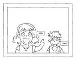
ディスプレイ装置3には、図1に示すように、2人の操作者候補を含む鏡面動画像が映し出されているものとする。なお、説明の便宜上ディスプレイ装置3に映し出される操作者候補の数を2人としたが、これは更に多くの人数でもよく、また、1人でもよい。1人の場合には、その操作者候補が操作者となる。
鏡面動画像は、ビデオカメラ1で撮影された動画像が、画像処理装置2に入力され、画像反転部102により画像が左右反転されることで生成される。左右反転した画像がディスプレイ装置に表示されることで、図1のような鏡面動画像が映し出される。[Example 1]
FIG. 4 is a flowchart for explaining the procedure of the image processing method of the present invention using the above-described image processing system.
As shown in FIG. 1, it is assumed that a mirror moving image including two operator candidates is displayed on the
The mirror moving image is generated by inputting a moving image captured by the
画像処理装置2は、操作者検出部109により鏡面動画像から顔センシング技術を用いて操作者候補の顔の位置を検出して、検出した位置を矩形のマーカ画像51、52で囲う(ステップS101)。マーカ画像51、52もオブジェクト画像の一種であり、画像合成部106は、操作者検出部109により操作者候補の顔の位置が検出されると、オブジェクト画像生成部105、オブジェクトデータ取得部104を介してオブジェクトデータ記憶部103からマーカ画像51、52のオブジェクト画像を取得し、これを鏡面動画像の該当する位置に合成する。表示制御部108は、このマーカ画像51、52が合成された鏡面動画像をディスプレイ装置3に表示させる(図5)。
なお、マーカ画像51、52は、矩形の他に、図6に示すような帯状として、操作者候補がヘアバンドをしているように表示してもよい。In the
In addition to the rectangle, the marker images 51 and 52 may be displayed as a band as shown in FIG. 6 so that the operator candidate has a hair band.
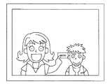
次いで操作者検出部109は、マーカ画像51、52に基づいて、鏡面動画像から操作者候補の顔領域を選択する(ステップS102)。顔領域を選択することで、図7のようなメニュー画像の提示候補領域が決められる。図7の例では、メニュー画像の提示候補領域が、予め顔領域の近傍に決められるようになっている。提示候補領域内の数字は、メニュー画像が提示される優先度を表しており、顔領域の下部(胸の辺り)の候補領域は優先度“1”であり、顔領域の右側近傍の候補領域は、優先度“2”で右手で操作できる領域である。顔領域の左側近傍の候補領域は、優先度“3”で左手で操作できる領域であり、顔領域の上部の候補領域は、優先度“4”で左右どちらの手でも操作できる領域である。2つの顔領域の中間の候補領域は、優先度“5”でどちらの操作者候補も操作できる領域である。
各提示候補領域は、優先度に応じてどの操作者候補でも同じ大きさに設定するようにしてもよいが、図7では、操作候補者毎に異なる大きさで設定している。図7では、左側の操作者候補が右側の操作者候補よりも大きく表示されているので、左側の操作者候補に対する提示候補領域が、右側の操作者候補の提示候補領域よりも大きく設定されている。つまり、提示候補領域の大きさは、操作者候補の顔領域の大きさに応じて変えるようにしてある。操作者候補の大きさは、操作者検出部109により顔の大きさを検出することで知ることができる。Next, based on the marker images 51 and 52, the operator detection unit 109 selects an operator candidate face area from the mirrored moving image (step S102). By selecting the face area, a menu image presentation candidate area as shown in FIG. 7 is determined. In the example of FIG. 7, the menu image presentation candidate area is determined in advance near the face area. The number in the presentation candidate area represents the priority at which the menu image is presented, the candidate area below the face area (around the chest) has the priority “1”, and the candidate area near the right side of the face area Is an area that can be operated with the right hand at the priority “2”. The candidate area near the left side of the face area is an area that can be operated with the left hand with the priority “3”, and the candidate area at the top of the face area is an area that can be operated with either the right or left hand with the priority “4”. An intermediate candidate area between the two face areas is an area where both operator candidates can be operated with the priority “5”.
Each candidate display area may be set to the same size for any operator candidate depending on the priority, but in FIG. 7, it is set to a different size for each operation candidate. In FIG. 7, since the left operator candidate is displayed larger than the right operator candidate, the presentation candidate area for the left operator candidate is set larger than the presentation candidate area of the right operator candidate. Yes. That is, the size of the presentation candidate area is changed according to the size of the face area of the operator candidate. The size of the operator candidate can be known by detecting the size of the face by the operator detection unit 109.
画像合成部106は、これらのメニュー画像の提示候補領域の中から実際にメニュー画像を提示する領域を選択する(ステップS103)。提示領域の選択は、例えば、画像比較部107により検出される、鏡面動画像の各部分における操作者候補の動き頻度、鏡面動画像の各領域の色の変化に応じて行うことができる。提示候補領域のうち、操作者候補の動きの頻度、色の変化により操作者候補が最も操作しやすい領域を選択する。この領域がメニュー画像を提示する領域となる。 The
前述のように、操作者候補の動きの頻度は差分画像を重ねることで検出することができる。図8は、差分画像を重ねて得られる動き画像マップの例示図である。このような動き画像マップにより、操作者候補の動きの頻度が密な領域と疎な領域とがわかる。図8の例では、手の頻繁に動く領域が、動きが密な領域として斜線で表されている。
色の変化は、図9に示すようなカラー領域マップを用いることで知ることができる。図9のカラー領域マップは、顔の色と同じ色が占める領域を斜線で示しており、斜線の領域以外で、顔の色と同じ色を検出することで、操作者候補が動いたことを検出できる。カラー領域マップは、例えば、顔センシング技術により操作者の顔の位置を検出する際に、顔の色を検出しておき、検出した顔の色と同系統の色の領域を鏡面動画像から検出することで生成することができる。As described above, the frequency of the motion of the operator candidate can be detected by overlapping the difference images. FIG. 8 is an exemplary view of a motion image map obtained by overlapping difference images. With such a motion image map, an area where the frequency of motion of the operator candidate is dense and a sparse area can be known. In the example of FIG. 8, a region where the hand moves frequently is represented by hatching as a region where the movement is dense.
The change in color can be known by using a color area map as shown in FIG. In the color area map of FIG. 9, the area occupied by the same color as the face color is indicated by hatching. By detecting the same color as the face color other than the hatched area, the operator candidate moves. It can be detected. For example, when detecting the position of the operator's face using face sensing technology, the color area map detects the face color and detects an area of the same color as the detected face color from the mirror moving image. Can be generated.
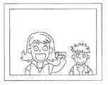
メニュー画像の提示領域が選択されると、画像合成部106は、鏡面動画像の該当領域にメニュー画像を合成した合成画像を生成する。表示制御部108は、ディスプレイ装置3に生成された合成画像を表示させる(ステップS104)。図10は、メニュー画像を提示したときの、ディスプレイ装置3に表示される画像の例示図である。この例では、2人の操作者候補のそれぞれ顔の近傍、優先度“2”の領域に、メニュー画像が提示されている。
図10では2つのメニュー画像の大きさを同じにしているが、操作者候補ごとに異なる大きさで提示するようにしてもよい。例えば、ディスプレイ装置3に映し出される操作者候補の大きさに応じてメニュー画像の大きさを変える。大きく映し出される操作者候補の提示候補領域ほど大きく設定されるので、提示候補領域から選択される提示領域も、大きく映し出される操作者候補ほど大きくなる。提示領域の大きさに合わせてメニュー画像を提示するようにすれば、大きく映し出される操作者候補ほどメニュー画像を大きく提示することができる。When the menu image presentation area is selected, the
In FIG. 10, the two menu images have the same size, but may be presented in different sizes for each operator candidate. For example, the size of the menu image is changed in accordance with the size of the operator candidate displayed on the
2人の操作者候補の一方が手を動かし、合成画像上で当該操作者候補の手がメニュー画像に触れる、或いは操作すると、操作者検出部109により当該操作者候補が操作者として選択される(ステップS105)。これにより実際に操作を行う操作者が決まる。
実際に操作を行う操作者が決まると、表示制御部108は、図11に示すように、選択した操作者を拡大して、画面中央に表示する(ステップS106)。また、メニュー画像は操作者に操作されているので、その下位層の「select1」、「select2」、「select3」のいずれかを表すプルダウン画像が表示される。
このようにして、操作者候補の近傍にメニュー画像を表示することが可能になり、操作のための煩雑な初期設定が不要になる。また、複数の操作者候補から実際に操作を行う操作者を選択することも容易に可能になる。When one of the two operator candidates moves his / her hand and the operator candidate's hand touches or operates the menu image on the composite image, the operator detection unit 109 selects the operator candidate as an operator. (Step S105). This determines the operator who actually performs the operation.
When the operator who actually performs the operation is determined, the
In this way, a menu image can be displayed in the vicinity of the operator candidate, and complicated initial settings for operation are not required. It is also possible to easily select an operator who actually performs an operation from a plurality of operator candidates.
[実施例2]
実施例1では、先にメニュー画像を操作した操作者候補を実際に操作を行う操作者として選択しているが、以下のようにステレオマッチングの手法を利用して実際に操作を行う操作者を選択するようにしてもよい。実施例2では、ビデオカメラ1を2台用意するなどして、2つの鏡面動画像を用意する。図12、13は2つの鏡面動画像にそれぞれメニュー画像を合成した合成画像の例示図である。[Example 2]
In the first embodiment, the operator candidate who has previously operated the menu image is selected as the operator who actually performs the operation. However, the operator who actually performs the operation using the stereo matching method as described below is selected. You may make it select. In the second embodiment, two mirror moving images are prepared by preparing two
2つの鏡面動画像は、例えば右目用及び左目用のステレオ画像である。図12、13の例では、図12が右目用画像、図13が左目用画像である。操作者検出部109は、これらの2つの合成画像を比較して、メニュー画像により近い方の操作者候補を操作者として選択する。図12、13の例では、いずれも左側の操作者候補がメニュー画像に近いために、左側を実際に操作する操作者とする。 The two specular moving images are stereo images for the right eye and the left eye, for example. In the examples of FIGS. 12 and 13, FIG. 12 shows a right-eye image, and FIG. 13 shows a left-eye image. The operator detection unit 109 compares these two composite images, and selects an operator candidate closer to the menu image as an operator. In the examples of FIGS. 12 and 13, since the left operator candidate is close to the menu image, it is assumed that the operator actually operates the left side.
以上のように、いずれの実施例においてもメニュー画像を操作者(又は操作者候補)が操作しやすい領域に容易に表示することができるので、鏡面動画像を用いた入力インタフェースにおける複雑な初期設定などが不要となる。また、複数の操作者候補から適宜1人を選択することができ、複数の人物が鏡面動画像内に表示される場合でも、初期設定が困難になったり、複数の操作者が同時に入力を行うことがないようにすることができる。 As described above, in any of the embodiments, a menu image can be easily displayed in an area that is easy for an operator (or an operator candidate) to operate, so that complicated initial setting in an input interface using a mirrored moving image is possible. Etc. become unnecessary. In addition, one person can be appropriately selected from a plurality of operator candidates, and even when a plurality of persons are displayed in a mirrored moving image, initial setting becomes difficult or a plurality of operators input simultaneously. You can prevent it from happening.
また、図8のような動き画像マップや図9のようなカラー領域マップを用いて、メニュー画像以外のオブジェクト画像を表示する領域を決めることもできる。
前述の通りこれらのマップは、操作者の動きを定量的に表すことができる。動き画像マップは、操作者の動きが多い領域、少ない領域、まったく動きのない領域を表すことができる。表示される差分画像が多い領域が操作者の動きが多い領域、差分画像が少ない領域が操作者の動きが少ない領域、差分画像がまったくない領域が操作者の動きがまったくない領域である。Further, it is possible to determine a region for displaying an object image other than the menu image by using a motion image map as shown in FIG. 8 or a color region map as shown in FIG.
As described above, these maps can quantitatively represent the movement of the operator. The motion image map can represent an area where the operator moves much, an area where there is little movement, or an area where there is no movement at all. A region with a large difference image to be displayed is a region with a large amount of operator movement, a region with a small difference image is a region with a small amount of operator movement, and a region without any difference image is a region with no movement of the operator.
カラー領域マップは、色の変化により操作者の動きを表すことができる。例えば1フレーム前のフレームの画面上の各領域の色と、現在のフレームの画面の各領域の色を比較することで、色が変化している領域を見つけることができる。まったく異なる色に変化している場合には操作者の動きがあったと判断できる。 The color area map can represent the movement of the operator by changing the color. For example, by comparing the color of each area on the screen of the previous frame with the color of each area of the screen of the current frame, it is possible to find an area where the color has changed. If the color has changed to a completely different color, it can be determined that the operator has moved.
図14は、操作者の動きに応じてオブジェクト画像を表示したときの例示図である。
図14では、操作者の他にベル画像141とボタン画像142とが表示されている。操作者がベル画像141に触れると、例えばベルが鳴る等のイベントが発生するようになっている。ボタン画像142を触れた場合には、ボタン画像に関連づけされたイベントが発生するようになっている。FIG. 14 is an exemplary diagram when an object image is displayed according to the movement of the operator.
In FIG. 14, a bell image 141 and a
ベル画像141は、操作者の動きの頻度が少ない領域に表示される。動き画像マップにより、操作者の動きの頻度がわかるので、画像合成部106は、これに応じて頻度が少ない領域を選択して、その領域にベル画像141が表示されるように合成画像を生成する。
ボタン画像142は、色の変化が大きい領域に表示される。カラー領域マップでは色の変化を検出できるため、画像合成部106は、これに応じて色の変化が大きい領域を選択して、その領域にボタン画像142が表示されるように合成画像を生成する。
このように、オブジェクト画像を操作者の動作に応じて配置することも容易に可能になる。The bell image 141 is displayed in an area where the frequency of movement of the operator is low. Since the frequency of the operator's movement is known from the motion image map, the
The
In this way, it is possible to easily arrange the object image according to the operation of the operator.
1 ビデオカメラ
2 画像処理装置
3 ディスプレイ装置
4 ビデオカメラ制御装置
101 画像入力部
102 画像反転部
103 オブジェクトデータ記憶部
104 オブジェクトデータ取得部
105 オブジェクト画像生成部
106 画像合成部
107 画像比較部
108 表示制御部
109 操作者検出部DESCRIPTION OF
Claims (17)
Translated fromJapanese前記鏡面動画像に含まれる前記複数の操作者候補のそれぞれの画像の位置を検出する検出手段を備え、
前記画像合成手段は、
前記検出手段により検出された前記複数の操作者候補のそれぞれの画像の位置に応じて、前記複数の操作者候補の手の画像が届く領域に前記オブジェクト画像が表示されるように、前記オブジェクト画像と前記鏡面動画像とを合成するように構成されている、
画像処理装置。Object image generation means for generating an object image for an object associated with a predetermined event, and the object image is combined with a mirrored moving imageincluding a plurality of operator candidate images thatcan be operators. An image processing unit for generating a composite image and displaying the composite image on a predetermined display device,
Detecting means for detecting the position ofeach of theplurality of operatorcandidates included in the specular moving image;
The image composition means includes
The object image is displayed such that the object image is displayed in an area where the images of the hands of theplurality of operatorcandidates reach according to the positions ofthe images of theplurality of operatorcandidates detected by the detection unit. And the mirror moving image are combined,
Image processing device.
取り込んだ動画像に鏡面処理を施して前記鏡面動画像を生成する画像反転手段と、をさらに備えている、
請求項1記載の画像処理装置。Image capturing means for capturing a moving image including a part of theplurality of operatorcandidate images photographed by a predetermined photographing device from the photographing device;
Image reversing means for generating a specular moving image by performing a specular process on the captured moving image;
The image processing apparatus according to claim 1.
前記画像合成手段は、検出された各顔の位置に応じた領域に前記オブジェクト画像が表示されるように、前記オブジェクト画像と前記鏡面動画像とを合成するように構成されている、
請求項1記載の画像処理装置。The detection means is configured to detect the position of the face ofeach operatorcandidate from the images of theplurality of operatorcandidates ,
The image synthesizing unit is configured to synthesize the object image and the specular moving image so that the object image is displayed in an area corresponding to the detected position ofeach face.
The image processing apparatus according to claim 1.
前記画像合成手段は、検出された前記複数の操作者候補の画像の大きさに応じた大きさに前記オブジェクト画像が表示されるように、前記オブジェクト画像と前記鏡面動画像とを合成するように構成されている、
請求項1記載の画像処理装置。The detection means is further configured to detect the size of the images of theplurality of operatorcandidates ,
The image synthesizing unit synthesizes the object image and the specular moving image so that the object image is displayed in a size corresponding to the size of the detected image of theplurality of operatorcandidates. It is configured,
The image processing apparatus according to claim 1.
前記検出手段により検出された前記複数の操作者候補のそれぞれの画像の位置に、当該操作者候補が検出されたことを示すマーカを表す画像を合成するように構成される、
請求項1記載の画像処理装置。The image composition means includes
Configured to synthesize an image representing a marker indicating that the operatorcandidate is detected ateach image position of theplurality of operatorcandidates detected by the detection means;
The image processing apparatus according to claim 1.
前記画像合成手段は、この動き画像マップにより得られる前記複数の操作者候補のそれぞれの画像の動きに応じて、前記オブジェクト画像を合成する領域を決めるように構成されている、
請求項1記載の画像処理装置。Means for generating a motion image map in which a plurality of difference images representing image differences between frames of the specular moving image are superimposed;
The image synthesizing unit is configured to determine a region for synthesizing the object image according to the movement ofeach of theplurality of operatorcandidates obtained from the motion image map.
The image processing apparatus according to claim 1.
前記画像合成手段は、この色の変化でにより得られる前記複数の操作者候補のそれぞれの画像の動きに応じて、前記オブジェクト画像を合成する領域を決めるように構成されている、
請求項1記載の画像処理装置。Comprising means for detecting a change in color of each region between frames of the specular moving image;
The image synthesizing unit is configured to determine a region for synthesizing the object image in accordance with movement ofeach of theplurality of operatorcandidates obtained by the color change.
The image processing apparatus according to claim 1.
選択された操作者候補の画像をズーム、パン、及び/又はチルトする表示制御手段と、をさらに備えている、
請求項1記載の画像処理装置。Means for selecting, as an image of the operator, an image of an operator candidate who has operated the object image when the object image is operated;
Display control means for zooming, panning and / or tilting the image of the selected operator candidate;
The image processing apparatus according to claim 1.
ステレオ画像を構成する複数の画像のそれぞれで前記オブジェクト画像に最も近い位置に表示される操作者候補の画像を前記操作者の画像に選択する手段と、
選択された操作者候補の画像をズーム、パン、及び/又はチルトする表示制御手段と、をさらに備えている、
請求項1記載の画像処理装置。When the mirror moving image is a stereo image taken simultaneously from a plurality of different angles,
Means for selecting, as the operator's image, an operator candidate image displayed at a position closest to the object image in each of a plurality of images constituting a stereo image;
Display control means for zooming, panning and / or tilting the image of the selected operator candidate;
The image processing apparatus according to claim1 .
前記画像合成手段は、各操作者候補の画像に対して、対応するオブジェクト画像を当該操作者候補の手の画像が届く範囲に表示されるように、前記複数のオブジェクト画像と前記鏡面動画像とを合成するように構成されている、
請求項1記載の画像処理装置。The object image generation means is configured to generate a plurality of object images corresponding to each of the operator candidates,
The image synthesizing unit is configured to display the corresponding object image for each operator candidate image in a range in which the image of the operator candidate's hand can reach. Is configured to synthesize,
The image processing apparatus according to claim1 .
選択された操作者候補の画像をズーム、パン、及び/又はチルトする表示制御手段と、をさらに備えている、
請求項10記載の画像処理装置。Means for selecting an operator candidate image corresponding to the object image as the operator image when any one of a plurality of object images is operated;
Display control means for zooming, panning and / or tilting the image of the selected operator candidate;
The image processing apparatus according to claim10 .
請求項8、9または11記載の画像処理装置。The display control unit is configured to perform zoom, pan, and / or tilt of the selected operator candidate image by digital processing.
The image processing apparatus according to claim8, 9 or 11 .
請求項8、9または11記載の画像処理装置。The display control means is configured to control zooming, panning, and / or tilting of an image of the selected operator candidate by controlling a photographing device for photographing the specular moving image.
The image processing apparatus according to claim8, 9 or 11 .
前記画像合成手段が、
前記検出手段により検出された前記複数の操作者候補のそれぞれの画像の位置に応じて、前記複数の操作者候補の手の画像が届く範囲に前記オブジェクト画像が表示されるように前記オブジェクト画像と前記鏡面動画像とを合成する、
画像処理方法。An image compositing means for generating a composite image including a mirror moving image including a part of images of aplurality of operator candidates that can be operators,and an object image of an object associated with a predetermined event; A method executed by an image processing apparatus, comprising: a detecting unit configured to detect a position ofeach of theplurality of operatorcandidates included in the specular moving image; and displaying the generated composite image on a predetermined display device Because
The image synthesizing means;
The object image and the object image are displayed in a range where the images of the hands of theplurality of operatorcandidates reach according to the positions ofthe images of theplurality of operatorcandidates detected by the detection unit. Synthesizing with the mirror moving image;
Image processing method.
所定のイベントに関連づけされたオブジェクトについてのオブジェクト画像を生成するオブジェクト画像生成手段、
操作者になり得る複数の操作者候補の画像をその一部に含んだ鏡面動画像に前記オブジェクト画像を合成して合成画像を生成する画像合成手段、
生成された合成画像を所定のディスプレイ装置に表示させる表示制御手段、
前記鏡面動画像に含まれる前記複数の操作者候補のそれぞれの画像の位置を検出する検出手段、を形成させ、
前記画像合成手段に、
前記検出手段により検出された前記複数の操作者候補のそれぞれの画像の位置に応じて、前記複数の操作者候補の手の画像が届く範囲に前記オブジェクト画像が表示されるように、前記オブジェクト画像と前記鏡面動画像とを合成する機能を形成させるためのコンピュータプログラム。To a computer connected to a display device,
Object image generation means for generating an object image for an object associated with a predetermined event;
Image synthesizing means for synthesizing the object image with a mirrored moving image including a part of images of aplurality of operator candidates that can become operators, and generating a synthesized image;
Display control means for displaying the generated composite image on a predetermined display device;
Detecting means for detecting the position ofeach of theplurality of operatorcandidates included in the mirrored moving image;
In the image composition means,
The object image is displayed such that the object image is displayed in a range where the images of the hands of theplurality of operatorcandidates reach according to the positions ofthe images of theplurality of operatorcandidates detected by the detection means. And a computer program for forming a function for synthesizing the mirror moving image.
所定のイベントに関連づけされたオブジェクトについてのオブジェクト画像を生成するオブジェクト画像生成手段、
操作者になり得る複数の操作者候補の画像をその一部に含んだ鏡面動画像に前記オブジェクト画像を合成して合成画像を生成する画像合成手段、
生成された合成画像を所定のディスプレイ装置に表示させる表示制御手段、
前記鏡面動画像に含まれる前記複数の操作者候補のそれぞれの画像の位置を検出する検出手段、を形成させ、
前記画像合成手段に、
前記検出手段により検出された前記複数の操作者候補のそれぞれの画像の位置に応じて、前記複数の操作者候補の手の画像が届く範囲に前記オブジェクト画像が表示されるように、前記オブジェクト画像と前記鏡面動画像とを合成する機能を形成させる半導体デバイス。By being incorporated into a device mounted on a computer to which a display device is connected,
Object image generation means for generating an object image for an object associated with a predetermined event;
Image synthesizing means for synthesizing the object image with a mirrored moving image including a part of images of aplurality of operator candidates that can become operators, and generating a synthesized image;
Display control means for displaying the generated composite image on a predetermined display device;
Detecting means for detecting the position ofeach of theplurality of operatorcandidates included in the mirrored moving image;
In the image composition means,
The object image is displayed such that the object image is displayed in a range where the images of the hands of theplurality of operatorcandidates reach according to the positions ofthe images of theplurality of operatorcandidates detected by the detection means. And a semiconductor device that forms a function of combining the mirror moving image.
Priority Applications (6)
| Application Number | Priority Date | Filing Date | Title |
|---|---|---|---|
| JP2004023013AJP3847753B2 (en) | 2004-01-30 | 2004-01-30 | Image processing apparatus, image processing method, recording medium, computer program, semiconductor device |
| EP12185924.3AEP2544073B1 (en) | 2004-01-30 | 2005-01-28 | Image processing device, image processing method, recording medium, computer program, and semiconductor device |
| EP05704389AEP1710663A4 (en) | 2004-01-30 | 2005-01-28 | Image processing device, image processing method, recording medium, computer program, anc semiconductor device |
| PCT/JP2005/001629WO2005078559A1 (en) | 2004-01-30 | 2005-01-28 | Image processing device, image processing method, recording medium, computer program, anc semiconductor device |
| US10/587,172US7999843B2 (en) | 2004-01-30 | 2005-01-28 | Image processor, image processing method, recording medium, computer program, and semiconductor device |
| US13/078,127US8508578B2 (en) | 2004-01-30 | 2011-04-01 | Image processor, image processing method, recording medium, computer program and semiconductor device |
Applications Claiming Priority (1)
| Application Number | Priority Date | Filing Date | Title |
|---|---|---|---|
| JP2004023013AJP3847753B2 (en) | 2004-01-30 | 2004-01-30 | Image processing apparatus, image processing method, recording medium, computer program, semiconductor device |
Related Child Applications (1)
| Application Number | Title | Priority Date | Filing Date |
|---|---|---|---|
| JP2006197392ADivisionJP4689548B2 (en) | 2006-07-19 | 2006-07-19 | Image processing apparatus, image processing method, recording medium, computer program, semiconductor device |
Publications (2)
| Publication Number | Publication Date |
|---|---|
| JP2005216061A JP2005216061A (en) | 2005-08-11 |
| JP3847753B2true JP3847753B2 (en) | 2006-11-22 |
Family
ID=34857618
Family Applications (1)
| Application Number | Title | Priority Date | Filing Date |
|---|---|---|---|
| JP2004023013AExpired - Fee RelatedJP3847753B2 (en) | 2004-01-30 | 2004-01-30 | Image processing apparatus, image processing method, recording medium, computer program, semiconductor device |
Country Status (4)
| Country | Link |
|---|---|
| US (2) | US7999843B2 (en) |
| EP (2) | EP2544073B1 (en) |
| JP (1) | JP3847753B2 (en) |
| WO (1) | WO2005078559A1 (en) |
Families Citing this family (107)
| Publication number | Priority date | Publication date | Assignee | Title |
|---|---|---|---|---|
| JP2007072564A (en)* | 2005-09-05 | 2007-03-22 | Sony Computer Entertainment Inc | Multimedia reproduction apparatus, menu operation reception method, and computer program |
| JP4781181B2 (en)* | 2006-07-07 | 2011-09-28 | 株式会社ソニー・コンピュータエンタテインメント | User interface program, apparatus and method, information processing system |
| JP4720738B2 (en)* | 2006-12-20 | 2011-07-13 | 日本ビクター株式会社 | Electronics |
| WO2008083205A2 (en) | 2006-12-29 | 2008-07-10 | Gesturetek, Inc. | Manipulation of virtual objects using enhanced interactive system |
| US8726194B2 (en) | 2007-07-27 | 2014-05-13 | Qualcomm Incorporated | Item selection using enhanced control |
| WO2009042579A1 (en) | 2007-09-24 | 2009-04-02 | Gesturetek, Inc. | Enhanced interface for voice and video communications |
| JP5088192B2 (en)* | 2008-03-21 | 2012-12-05 | 富士ゼロックス株式会社 | Drawing apparatus and program |
| JP2009237630A (en)* | 2008-03-25 | 2009-10-15 | Seiko Epson Corp | Method, unit and program for display control, and printer unit |
| JP4985531B2 (en)* | 2008-04-18 | 2012-07-25 | パナソニック株式会社 | Mirror system |
| JP2009265709A (en)* | 2008-04-22 | 2009-11-12 | Hitachi Ltd | Input device |
| JP5258399B2 (en)* | 2008-06-06 | 2013-08-07 | キヤノン株式会社 | Image projection apparatus and control method thereof |
| US8133119B2 (en)* | 2008-10-01 | 2012-03-13 | Microsoft Corporation | Adaptation for alternate gaming input devices |
| JP5255397B2 (en)* | 2008-10-15 | 2013-08-07 | パナソニック株式会社 | Image display method and display |
| JP5706340B2 (en)* | 2009-01-21 | 2015-04-22 | トムソン ライセンシングThomson Licensing | Method for controlling media by face detection and hot spot movement |
| US8295546B2 (en) | 2009-01-30 | 2012-10-23 | Microsoft Corporation | Pose tracking pipeline |
| US8866821B2 (en) | 2009-01-30 | 2014-10-21 | Microsoft Corporation | Depth map movement tracking via optical flow and velocity prediction |
| US9652030B2 (en)* | 2009-01-30 | 2017-05-16 | Microsoft Technology Licensing, Llc | Navigation of a virtual plane using a zone of restriction for canceling noise |
| US8294767B2 (en)* | 2009-01-30 | 2012-10-23 | Microsoft Corporation | Body scan |
| US8773355B2 (en)* | 2009-03-16 | 2014-07-08 | Microsoft Corporation | Adaptive cursor sizing |
| US8988437B2 (en) | 2009-03-20 | 2015-03-24 | Microsoft Technology Licensing, Llc | Chaining animations |
| US9256282B2 (en) | 2009-03-20 | 2016-02-09 | Microsoft Technology Licensing, Llc | Virtual object manipulation |
| US9377857B2 (en) | 2009-05-01 | 2016-06-28 | Microsoft Technology Licensing, Llc | Show body position |
| US8181123B2 (en)* | 2009-05-01 | 2012-05-15 | Microsoft Corporation | Managing virtual port associations to users in a gesture-based computing environment |
| US8503720B2 (en) | 2009-05-01 | 2013-08-06 | Microsoft Corporation | Human body pose estimation |
| US8942428B2 (en) | 2009-05-01 | 2015-01-27 | Microsoft Corporation | Isolate extraneous motions |
| US9015638B2 (en)* | 2009-05-01 | 2015-04-21 | Microsoft Technology Licensing, Llc | Binding users to a gesture based system and providing feedback to the users |
| US9498718B2 (en)* | 2009-05-01 | 2016-11-22 | Microsoft Technology Licensing, Llc | Altering a view perspective within a display environment |
| US8340432B2 (en) | 2009-05-01 | 2012-12-25 | Microsoft Corporation | Systems and methods for detecting a tilt angle from a depth image |
| US8649554B2 (en) | 2009-05-01 | 2014-02-11 | Microsoft Corporation | Method to control perspective for a camera-controlled computer |
| US8638985B2 (en) | 2009-05-01 | 2014-01-28 | Microsoft Corporation | Human body pose estimation |
| US9898675B2 (en) | 2009-05-01 | 2018-02-20 | Microsoft Technology Licensing, Llc | User movement tracking feedback to improve tracking |
| US8253746B2 (en)* | 2009-05-01 | 2012-08-28 | Microsoft Corporation | Determine intended motions |
| US20100277470A1 (en)* | 2009-05-01 | 2010-11-04 | Microsoft Corporation | Systems And Methods For Applying Model Tracking To Motion Capture |
| US20100295771A1 (en)* | 2009-05-20 | 2010-11-25 | Microsoft Corporation | Control of display objects |
| US8542252B2 (en) | 2009-05-29 | 2013-09-24 | Microsoft Corporation | Target digitization, extraction, and tracking |
| US9400559B2 (en) | 2009-05-29 | 2016-07-26 | Microsoft Technology Licensing, Llc | Gesture shortcuts |
| US8856691B2 (en)* | 2009-05-29 | 2014-10-07 | Microsoft Corporation | Gesture tool |
| US8803889B2 (en) | 2009-05-29 | 2014-08-12 | Microsoft Corporation | Systems and methods for applying animations or motions to a character |
| US8320619B2 (en) | 2009-05-29 | 2012-11-27 | Microsoft Corporation | Systems and methods for tracking a model |
| US9182814B2 (en)* | 2009-05-29 | 2015-11-10 | Microsoft Technology Licensing, Llc | Systems and methods for estimating a non-visible or occluded body part |
| US8379101B2 (en)* | 2009-05-29 | 2013-02-19 | Microsoft Corporation | Environment and/or target segmentation |
| US8744121B2 (en) | 2009-05-29 | 2014-06-03 | Microsoft Corporation | Device for identifying and tracking multiple humans over time |
| US8625837B2 (en)* | 2009-05-29 | 2014-01-07 | Microsoft Corporation | Protocol and format for communicating an image from a camera to a computing environment |
| US20100306716A1 (en)* | 2009-05-29 | 2010-12-02 | Microsoft Corporation | Extending standard gestures |
| US8509479B2 (en) | 2009-05-29 | 2013-08-13 | Microsoft Corporation | Virtual object |
| US8145594B2 (en)* | 2009-05-29 | 2012-03-27 | Microsoft Corporation | Localized gesture aggregation |
| US9383823B2 (en) | 2009-05-29 | 2016-07-05 | Microsoft Technology Licensing, Llc | Combining gestures beyond skeletal |
| US8418085B2 (en)* | 2009-05-29 | 2013-04-09 | Microsoft Corporation | Gesture coach |
| US20100302138A1 (en)* | 2009-05-29 | 2010-12-02 | Microsoft Corporation | Methods and systems for defining or modifying a visual representation |
| US8176442B2 (en)* | 2009-05-29 | 2012-05-08 | Microsoft Corporation | Living cursor control mechanics |
| US7914344B2 (en)* | 2009-06-03 | 2011-03-29 | Microsoft Corporation | Dual-barrel, connector jack and plug assemblies |
| US8390680B2 (en) | 2009-07-09 | 2013-03-05 | Microsoft Corporation | Visual representation expression based on player expression |
| US9159151B2 (en)* | 2009-07-13 | 2015-10-13 | Microsoft Technology Licensing, Llc | Bringing a visual representation to life via learned input from the user |
| US8847984B2 (en)* | 2009-07-27 | 2014-09-30 | Disney Enterprises, Inc. | System and method for forming a composite image in a portable computing device having a dual screen display |
| US20110025689A1 (en)* | 2009-07-29 | 2011-02-03 | Microsoft Corporation | Auto-Generating A Visual Representation |
| US9277021B2 (en)* | 2009-08-21 | 2016-03-01 | Avaya Inc. | Sending a user associated telecommunication address |
| US9141193B2 (en)* | 2009-08-31 | 2015-09-22 | Microsoft Technology Licensing, Llc | Techniques for using human gestures to control gesture unaware programs |
| US20110109617A1 (en)* | 2009-11-12 | 2011-05-12 | Microsoft Corporation | Visualizing Depth |
| JP4900741B2 (en)* | 2010-01-29 | 2012-03-21 | 島根県 | Image recognition apparatus, operation determination method, and program |
| JP5114795B2 (en)* | 2010-01-29 | 2013-01-09 | 島根県 | Image recognition apparatus, operation determination method, and program |
| JP5659510B2 (en)* | 2010-03-10 | 2015-01-28 | ソニー株式会社 | Image processing apparatus, image processing method, and program |
| US8515137B2 (en) | 2010-05-03 | 2013-08-20 | Microsoft Corporation | Generating a combined image from multiple images |
| WO2012014590A1 (en)* | 2010-07-28 | 2012-02-02 | パイオニア株式会社 | Video processing device and method |
| KR101790342B1 (en)* | 2010-09-14 | 2017-10-26 | 엘지전자 주식회사 | Display apparatus and controlling method thereof |
| JP2012118448A (en)* | 2010-12-03 | 2012-06-21 | Sony Corp | Image processing method, image processing apparatus and image processing program |
| US8942917B2 (en) | 2011-02-14 | 2015-01-27 | Microsoft Corporation | Change invariant scene recognition by an agent |
| US10146423B1 (en) | 2011-04-07 | 2018-12-04 | Wells Fargo Bank, N.A. | System and method for generating a position based user interface |
| WO2012144145A1 (en)* | 2011-04-22 | 2012-10-26 | パナソニック株式会社 | Pointing control device, integrated circuit thereof, and pointing control method |
| US8620113B2 (en) | 2011-04-25 | 2013-12-31 | Microsoft Corporation | Laser diode modes |
| US20120288251A1 (en)* | 2011-05-13 | 2012-11-15 | Cyberlink Corp. | Systems and methods for utilizing object detection to adaptively adjust controls |
| US8760395B2 (en) | 2011-05-31 | 2014-06-24 | Microsoft Corporation | Gesture recognition techniques |
| US20130088511A1 (en)* | 2011-10-10 | 2013-04-11 | Sanjit K. Mitra | E-book reader with overlays |
| US9164579B2 (en)* | 2011-11-15 | 2015-10-20 | Lg Electronics Inc. | Electronic device for granting authority based on context awareness information |
| US8635637B2 (en) | 2011-12-02 | 2014-01-21 | Microsoft Corporation | User interface presenting an animated avatar performing a media reaction |
| US9100685B2 (en) | 2011-12-09 | 2015-08-04 | Microsoft Technology Licensing, Llc | Determining audience state or interest using passive sensor data |
| JP6243112B2 (en) | 2011-12-09 | 2017-12-06 | ソニー株式会社 | Information processing apparatus, information processing method, and recording medium |
| EP2828768A4 (en)* | 2012-03-20 | 2015-10-14 | A9 Com Inc | Structured lighting-based content interactions in multiple environments |
| US9373025B2 (en) | 2012-03-20 | 2016-06-21 | A9.Com, Inc. | Structured lighting-based content interactions in multiple environments |
| US8898687B2 (en) | 2012-04-04 | 2014-11-25 | Microsoft Corporation | Controlling a media program based on a media reaction |
| CA2775700C (en) | 2012-05-04 | 2013-07-23 | Microsoft Corporation | Determining a future portion of a currently presented media program |
| JP2013250882A (en)* | 2012-06-01 | 2013-12-12 | Sharp Corp | Attention position detection device, attention position detection method, and attention position detection program |
| JP5935529B2 (en) | 2012-06-13 | 2016-06-15 | ソニー株式会社 | Image processing apparatus, image processing method, and program |
| USD711410S1 (en)* | 2012-06-13 | 2014-08-19 | Microsoft Corporation | Display screen with graphical user interface |
| JP6021488B2 (en)* | 2012-07-19 | 2016-11-09 | キヤノン株式会社 | Control device, control method, and control program |
| US9087402B2 (en)* | 2013-03-13 | 2015-07-21 | Microsoft Technology Licensing, Llc | Augmenting images with higher resolution data |
| EP2919099B1 (en)* | 2012-11-06 | 2020-04-15 | Sony Interactive Entertainment Inc. | Information processing device |
| US20140146155A1 (en)* | 2012-11-24 | 2014-05-29 | Novarad Corporation | Image Processing |
| JP2014127124A (en)* | 2012-12-27 | 2014-07-07 | Sony Corp | Information processing apparatus, information processing method, and program |
| US9857470B2 (en) | 2012-12-28 | 2018-01-02 | Microsoft Technology Licensing, Llc | Using photometric stereo for 3D environment modeling |
| US9940553B2 (en) | 2013-02-22 | 2018-04-10 | Microsoft Technology Licensing, Llc | Camera/object pose from predicted coordinates |
| CN104104865B (en)* | 2013-04-02 | 2017-07-11 | 宏达国际电子股份有限公司 | Control method and electronic device |
| US9749541B2 (en)* | 2013-04-16 | 2017-08-29 | Tout Inc. | Method and apparatus for displaying and recording images using multiple image capturing devices integrated into a single mobile device |
| JP2015056141A (en)* | 2013-09-13 | 2015-03-23 | ソニー株式会社 | Information processing device and information processing method |
| US10080963B2 (en) | 2014-03-28 | 2018-09-25 | Sony Interactive Entertainment Inc. | Object manipulation method, object manipulation program, and information processing apparatus |
| JP2015191480A (en)* | 2014-03-28 | 2015-11-02 | 株式会社ソニー・コンピュータエンタテインメント | Information processor, operation method of object and operation program of object |
| JP2015233250A (en)* | 2014-06-10 | 2015-12-24 | キヤノン株式会社 | Image processing apparatus and control method thereof |
| US20160093081A1 (en)* | 2014-09-26 | 2016-03-31 | Samsung Electronics Co., Ltd. | Image display method performed by device including switchable mirror and the device |
| KR102322034B1 (en)* | 2014-09-26 | 2021-11-04 | 삼성전자주식회사 | Image display method of a apparatus with a switchable mirror and the apparatus |
| US10699454B2 (en)* | 2014-12-30 | 2020-06-30 | Facebook, Inc. | Systems and methods for providing textual social remarks overlaid on media content |
| KR102375699B1 (en)* | 2015-02-06 | 2022-03-17 | 삼성전자 주식회사 | Electronic device and method for providing user interface thereof |
| JP6448500B2 (en)* | 2015-08-07 | 2019-01-09 | キヤノン株式会社 | Image processing apparatus and image processing method |
| JP6702746B2 (en)* | 2016-02-10 | 2020-06-03 | キヤノン株式会社 | Imaging device, control method thereof, program, and storage medium |
| JP2018109813A (en)* | 2016-12-28 | 2018-07-12 | 富士ゼロックス株式会社 | Display device, image forming apparatus, and program |
| CN107493495B (en)* | 2017-08-14 | 2019-12-13 | 深圳市国华识别科技开发有限公司 | Interactive position determining method, system, storage medium and intelligent terminal |
| JP7286967B2 (en)* | 2019-01-08 | 2023-06-06 | 京セラドキュメントソリューションズ株式会社 | Display device and display control program |
| CN114237779A (en)* | 2020-09-09 | 2022-03-25 | 华为技术有限公司 | Method for displaying windows, method for switching windows, electronic device and system |
| US12432080B2 (en)* | 2022-11-14 | 2025-09-30 | Microsoft Technology Licensing, Llc | Persistent display of prioritized participants with shared content of communication sessions |
Family Cites Families (13)
| Publication number | Priority date | Publication date | Assignee | Title |
|---|---|---|---|---|
| US5423554A (en)* | 1993-09-24 | 1995-06-13 | Metamedia Ventures, Inc. | Virtual reality game method and apparatus |
| CN1135823A (en)* | 1993-10-20 | 1996-11-13 | 电视会议系统公司 | Adaptive videoconferencing system |
| JPH08263194A (en) | 1995-03-22 | 1996-10-11 | Kyushu Nippon Denki Software Kk | Key input device |
| US6256046B1 (en)* | 1997-04-18 | 2001-07-03 | Compaq Computer Corporation | Method and apparatus for visual sensing of humans for active public interfaces |
| US6188777B1 (en)* | 1997-08-01 | 2001-02-13 | Interval Research Corporation | Method and apparatus for personnel detection and tracking |
| US6353764B1 (en)* | 1997-11-27 | 2002-03-05 | Matsushita Electric Industrial Co., Ltd. | Control method |
| JPH11327753A (en) | 1997-11-27 | 1999-11-30 | Matsushita Electric Ind Co Ltd | Control method and program recording medium |
| JP4258123B2 (en) | 1998-05-19 | 2009-04-30 | 株式会社ソニー・コンピュータエンタテインメント | Image processing apparatus and method, and providing medium |
| JP4332649B2 (en)* | 1999-06-08 | 2009-09-16 | 独立行政法人情報通信研究機構 | Hand shape and posture recognition device, hand shape and posture recognition method, and recording medium storing a program for executing the method |
| JP3725460B2 (en)* | 2000-10-06 | 2005-12-14 | 株式会社ソニー・コンピュータエンタテインメント | Image processing apparatus, image processing method, recording medium, computer program, semiconductor device |
| US20020126090A1 (en)* | 2001-01-18 | 2002-09-12 | International Business Machines Corporation | Navigating and selecting a portion of a screen by utilizing a state of an object as viewed by a camera |
| US7174510B2 (en)* | 2001-10-20 | 2007-02-06 | Hal Christopher Salter | Interactive game providing instruction in musical notation and in learning an instrument |
| US7283983B2 (en)* | 2003-01-09 | 2007-10-16 | Evolution Robotics, Inc. | Computer and vision-based augmented interaction in the use of printed media |
- 2004
- 2004-01-30JPJP2004023013Apatent/JP3847753B2/ennot_activeExpired - Fee Related
- 2005
- 2005-01-28EPEP12185924.3Apatent/EP2544073B1/ennot_activeCeased
- 2005-01-28USUS10/587,172patent/US7999843B2/enactiveActive
- 2005-01-28EPEP05704389Apatent/EP1710663A4/ennot_activeCeased
- 2005-01-28WOPCT/JP2005/001629patent/WO2005078559A1/enactiveApplication Filing
- 2011
- 2011-04-01USUS13/078,127patent/US8508578B2/ennot_activeExpired - Fee Related
Also Published As
| Publication number | Publication date |
|---|---|
| EP2544073A2 (en) | 2013-01-09 |
| EP2544073B1 (en) | 2014-12-03 |
| JP2005216061A (en) | 2005-08-11 |
| EP1710663A1 (en) | 2006-10-11 |
| US8508578B2 (en) | 2013-08-13 |
| US20110181621A1 (en) | 2011-07-28 |
| WO2005078559A1 (en) | 2005-08-25 |
| US20070279485A1 (en) | 2007-12-06 |
| EP1710663A4 (en) | 2011-02-16 |
| EP2544073A3 (en) | 2013-03-27 |
| US7999843B2 (en) | 2011-08-16 |
Similar Documents
| Publication | Publication Date | Title |
|---|---|---|
| JP3847753B2 (en) | Image processing apparatus, image processing method, recording medium, computer program, semiconductor device | |
| JP3725460B2 (en) | Image processing apparatus, image processing method, recording medium, computer program, semiconductor device | |
| US8648924B2 (en) | Computer-readable storage medium having stored thereon image generation program, capturing apparatus, capturing system, and image generation method for generating a combination image on a display of the capturing apparatus | |
| US20150042647A1 (en) | Image-processing system, image-processing method and program | |
| US8860847B2 (en) | Computer-readable storage medium having stored thereon image generation program, capturing apparatus, capturing system, and image generation method for creating an image | |
| KR20150119621A (en) | display apparatus and image composition method thereof | |
| JP4689548B2 (en) | Image processing apparatus, image processing method, recording medium, computer program, semiconductor device | |
| JP2023017920A (en) | Image processing device | |
| JP6621565B2 (en) | Display control apparatus, display control method, and program | |
| US8798326B2 (en) | Photographed image storage control unit, photographed image storage control method, photographed image storage control program, and storage medium stored with the photographed image storage control program | |
| JP5805013B2 (en) | Captured image display device, captured image display method, and program | |
| JP2004178036A (en) | A virtual space presentation device with a remote person's image | |
| JP4824409B2 (en) | Information processing system, entertainment system, and information receiving method for information processing system | |
| JP4767331B2 (en) | Image processing apparatus, image processing method, recording medium, computer program, semiconductor device | |
| JP2023161493A (en) | Display system, display method, and display program | |
| JP6371547B2 (en) | Image processing apparatus, method, and program | |
| JP4544262B2 (en) | Virtual reality space sharing system and method, and information processing apparatus and method | |
| JP4615252B2 (en) | Image processing apparatus, image processing method, recording medium, computer program, semiconductor device | |
| WO2018168825A1 (en) | Image processing device and electronic equipment | |
| JP6514386B1 (en) | PROGRAM, RECORDING MEDIUM, AND IMAGE GENERATION METHOD | |
| JP5245156B2 (en) | Camera system, image information reproducing means therefor, and image information reproducing means | |
| JP2012156628A (en) | Electronic camera, image processing apparatus, and image processing program | |
| JP2003163823A (en) | Image processing apparatus, photographing device, image processing method, program, and computer-readable storage medium | |
| WO2018168824A1 (en) | Image processing device and electronic equipment |
Legal Events
| Date | Code | Title | Description |
|---|---|---|---|
| A131 | Notification of reasons for refusal | Free format text:JAPANESE INTERMEDIATE CODE: A131 Effective date:20060530 | |
| A521 | Request for written amendment filed | Free format text:JAPANESE INTERMEDIATE CODE: A523 Effective date:20060719 | |
| TRDD | Decision of grant or rejection written | ||
| A01 | Written decision to grant a patent or to grant a registration (utility model) | Free format text:JAPANESE INTERMEDIATE CODE: A01 Effective date:20060822 | |
| A61 | First payment of annual fees (during grant procedure) | Free format text:JAPANESE INTERMEDIATE CODE: A61 Effective date:20060823 | |
| R150 | Certificate of patent or registration of utility model | Ref document number:3847753 Country of ref document:JP Free format text:JAPANESE INTERMEDIATE CODE: R150 | |
| FPAY | Renewal fee payment (event date is renewal date of database) | Free format text:PAYMENT UNTIL: 20090901 Year of fee payment:3 | |
| FPAY | Renewal fee payment (event date is renewal date of database) | Free format text:PAYMENT UNTIL: 20100901 Year of fee payment:4 | |
| R250 | Receipt of annual fees | Free format text:JAPANESE INTERMEDIATE CODE: R250 | |
| FPAY | Renewal fee payment (event date is renewal date of database) | Free format text:PAYMENT UNTIL: 20100901 Year of fee payment:4 | |
| FPAY | Renewal fee payment (event date is renewal date of database) | Free format text:PAYMENT UNTIL: 20110901 Year of fee payment:5 | |
| R250 | Receipt of annual fees | Free format text:JAPANESE INTERMEDIATE CODE: R250 | |
| FPAY | Renewal fee payment (event date is renewal date of database) | Free format text:PAYMENT UNTIL: 20120901 Year of fee payment:6 | |
| R250 | Receipt of annual fees | Free format text:JAPANESE INTERMEDIATE CODE: R250 | |
| FPAY | Renewal fee payment (event date is renewal date of database) | Free format text:PAYMENT UNTIL: 20130901 Year of fee payment:7 | |
| R250 | Receipt of annual fees | Free format text:JAPANESE INTERMEDIATE CODE: R250 | |
| R250 | Receipt of annual fees | Free format text:JAPANESE INTERMEDIATE CODE: R250 | |
| R250 | Receipt of annual fees | Free format text:JAPANESE INTERMEDIATE CODE: R250 | |
| R250 | Receipt of annual fees | Free format text:JAPANESE INTERMEDIATE CODE: R250 | |
| R250 | Receipt of annual fees | Free format text:JAPANESE INTERMEDIATE CODE: R250 | |
| R250 | Receipt of annual fees | Free format text:JAPANESE INTERMEDIATE CODE: R250 | |
| R250 | Receipt of annual fees | Free format text:JAPANESE INTERMEDIATE CODE: R250 | |
| R250 | Receipt of annual fees | Free format text:JAPANESE INTERMEDIATE CODE: R250 | |
| R250 | Receipt of annual fees | Free format text:JAPANESE INTERMEDIATE CODE: R250 | |
| R250 | Receipt of annual fees | Free format text:JAPANESE INTERMEDIATE CODE: R250 | |
| LAPS | Cancellation because of no payment of annual fees |