JP3847702B2 - Vehicle steering control device - Google Patents
Vehicle steering control deviceDownload PDFInfo
- Publication number
- JP3847702B2 JP3847702B2JP2002349893AJP2002349893AJP3847702B2JP 3847702 B2JP3847702 B2JP 3847702B2JP 2002349893 AJP2002349893 AJP 2002349893AJP 2002349893 AJP2002349893 AJP 2002349893AJP 3847702 B2JP3847702 B2JP 3847702B2
- Authority
- JP
- Japan
- Prior art keywords
- control
- motor
- torque
- ecu
- torque command
- Prior art date
- Legal status (The legal status is an assumption and is not a legal conclusion. Google has not performed a legal analysis and makes no representation as to the accuracy of the status listed.)
- Expired - Fee Related
Links
Images


Classifications
- H—ELECTRICITY
- H02—GENERATION; CONVERSION OR DISTRIBUTION OF ELECTRIC POWER
- H02P—CONTROL OR REGULATION OF ELECTRIC MOTORS, ELECTRIC GENERATORS OR DYNAMO-ELECTRIC CONVERTERS; CONTROLLING TRANSFORMERS, REACTORS OR CHOKE COILS
- H02P5/00—Arrangements specially adapted for regulating or controlling the speed or torque of two or more electric motors
- H02P5/68—Arrangements specially adapted for regulating or controlling the speed or torque of two or more electric motors controlling two or more DC dynamo-electric motors
- H02P5/69—Arrangements specially adapted for regulating or controlling the speed or torque of two or more electric motors controlling two or more DC dynamo-electric motors mechanically coupled by gearing
- B—PERFORMING OPERATIONS; TRANSPORTING
- B62—LAND VEHICLES FOR TRAVELLING OTHERWISE THAN ON RAILS
- B62D—MOTOR VEHICLES; TRAILERS
- B62D5/00—Power-assisted or power-driven steering
- B62D5/001—Mechanical components or aspects of steer-by-wire systems, not otherwise provided for in this maingroup
- B62D5/003—Backup systems, e.g. for manual steering
- B—PERFORMING OPERATIONS; TRANSPORTING
- B62—LAND VEHICLES FOR TRAVELLING OTHERWISE THAN ON RAILS
- B62D—MOTOR VEHICLES; TRAILERS
- B62D5/00—Power-assisted or power-driven steering
- B62D5/04—Power-assisted or power-driven steering electrical, e.g. using an electric servo-motor connected to, or forming part of, the steering gear
- B62D5/0403—Power-assisted or power-driven steering electrical, e.g. using an electric servo-motor connected to, or forming part of, the steering gear characterised by constructional features, e.g. common housing for motor and gear box
- B—PERFORMING OPERATIONS; TRANSPORTING
- B62—LAND VEHICLES FOR TRAVELLING OTHERWISE THAN ON RAILS
- B62D—MOTOR VEHICLES; TRAILERS
- B62D5/00—Power-assisted or power-driven steering
- B62D5/04—Power-assisted or power-driven steering electrical, e.g. using an electric servo-motor connected to, or forming part of, the steering gear
- B62D5/0457—Power-assisted or power-driven steering electrical, e.g. using an electric servo-motor connected to, or forming part of, the steering gear characterised by control features of the drive means as such
- B62D5/0481—Power-assisted or power-driven steering electrical, e.g. using an electric servo-motor connected to, or forming part of, the steering gear characterised by control features of the drive means as such monitoring the steering system, e.g. failures
- B62D5/0484—Power-assisted or power-driven steering electrical, e.g. using an electric servo-motor connected to, or forming part of, the steering gear characterised by control features of the drive means as such monitoring the steering system, e.g. failures for reaction to failures, e.g. limp home
- H—ELECTRICITY
- H02—GENERATION; CONVERSION OR DISTRIBUTION OF ELECTRIC POWER
- H02P—CONTROL OR REGULATION OF ELECTRIC MOTORS, ELECTRIC GENERATORS OR DYNAMO-ELECTRIC CONVERTERS; CONTROLLING TRANSFORMERS, REACTORS OR CHOKE COILS
- H02P21/00—Arrangements or methods for the control of electric machines by vector control, e.g. by control of field orientation
Landscapes
- Engineering & Computer Science (AREA)
- Chemical & Material Sciences (AREA)
- Combustion & Propulsion (AREA)
- Transportation (AREA)
- Mechanical Engineering (AREA)
- Power Engineering (AREA)
- Power Steering Mechanism (AREA)
- Steering Control In Accordance With Driving Conditions (AREA)
Description
Translated fromJapanese【0001】
【発明の属する技術分野】
本発明は、ステアバイワイヤ式の操舵制御装置や電動パワーステアリング制御装置に使用される車両の操舵制御装置に関するものである。
【0002】
【従来の技術】
従来、車両の操舵輪を制御する車両の操舵制御装置として、ステアリングホイールと、前輪(操舵輪)に連結する操舵用ギヤボックスとを機械的に分離したステアバイワイヤ式の操舵制御装置が公知である。
【0003】
この操舵制御装置は、ステアリングホイールと操舵用ギヤボックスとを直結しないで、ステアリングホイールの操舵角を検出し、検出した操舵角に応じて電動モータを介して操舵用ギヤボックスを駆動するようにされている。
【0004】
この種の操舵制御装置では、装置の故障時に確実にステアリング操作が続行できるよう、何らかのバックアップシステムを設けている。
このバックアップシステムとしては、例えば2つの冗長なシステムを備えた構成が提案されている(特許文献1参照)。
【0005】
1つのシステムは、主システムとされ、操舵輪に連結したシャフトを駆動する1つの電動モータと、同モータを駆動する1つの駆動回路、及び前記駆動回路を介して電動モータを駆動制御する1つの制御回路や制御に必要な各種センサが設けられている。又、他の1つのシステムは、副システムとされ、主システムと同様の構成を備えている。
【0006】
2つのシステムを備えた装置では、各システムが正常時には、相互干渉しないようにして、両システムの各モータを同時に駆動制御し、主システム側の電動モータにて、ステアリングホイールの操舵角に応じてシャフトを駆動する。
【0007】
そして、主システム側になんらかの故障があった場合には、その電動モータを停止させ、残る副システム側の電動モータにてシャフトを駆動するようにされている。
【0008】
又、特許文献2では、相異なる位置に操舵用モータを一対配置し、操舵に必要な操舵力を所定の比率に分配する舵取機構が提案されている。
【0009】
【特許文献1】
特開2002−37112号公報(図1、段落「0015」〜「0028」)
【特許文献2】
特開平10−218000号公報
【0010】
【発明が解決しようとする課題】
ところで、電動モータの制御方式は、ステアリングホイールの操舵角を検出する操舵角センサの検出値に基づいて電動モータを位置制御するようにしている。このとき、複数の電動モータを同時に駆動しようとした場合、モータトルクの干渉が問題になる場合がある。
【0011】
例えば、各電動モータに設けた回転角センサによる電動モータの回転角に基づいて位置フィードバック制御を行う場合、電動モータの組付誤差や、回転角センサの組付誤差などにより、各電動モータは異なった位置に制御されてしまう。このため、発生トルクの方向が合わず、トルクが低下したり、音や振動が発生したり、さらには電動モータが発熱してしまう問題がある。
【0012】
特許文献1の技術では、両システムの制御誤差により生ずる相互干渉を回避するために、相互干渉が生ずる部位に相互干渉検知機構を設けている。相互干渉検知機構は、相互干渉を検知すると、一方のシステムの作動(電動モータの作動を含む)を停止させるようにしている。
【0013】
前記モータトルクの干渉が生じた場合、この制御誤差による相互干渉が生じた場合と同様に、一方のシステムを停止することが考えられる。
しかし、この制御の方法では、一方のシステムの作動を停止してしまうため、両システム自体は正常であるにも拘わらず、残った電動モータのみによって操舵輪に連結したシャフトを駆動することになり、システムが正常時においては、好ましくない方法である。
【0014】
又、特許法文献2の技術では、相異なる位置に一対の操舵用モータ(主及び副操舵用モータ)を配置しているため、主操舵用モータと副操舵用モータとでは、モータ形状、構成がそれぞれ異なることを前提とした技術である。
【0015】
従って、モータの性能(モータ特性)が均一でないことから、トルク分配を所定の比率でしか分配できない。又、どちらのモータが故障したかにより、故障後の性能に差が生ずることになる。
【0016】
本発明の目的は、複数のシステムの各電動モータを同時駆動する際、電動モータのトルク干渉の問題を解消して、トルクの低下を生ずることがなく、異音、振動、発熱の発生を抑えることができる車両の操舵制御装置を提供することにある。
【0017】
又、本発明の目的は、複数のモータ間の性能差による制約がないため、システム故障時のトルクの分配が容易であり、性能低下を防ぐことができる車両の操舵制御装置を提供することにある。
【0018】
【課題を解決するための手段】
上記問題点を解決するために、請求項1に記載の発明は、車両舵取機構の操舵輪上に同軸形状に一体配置された複数個の概同一性能の電動モータと、前記各電動モータを制御する制御手段を含む複数のシステムを備え、各システムの電動モータを同時に制御して共通の前記舵取機構を駆動する車両の操舵制御装置において、1つのシステムの制御手段は、操舵ハンドルの操舵位置と自身のシステムの電動モータの位置情報に基づいて前記舵取機構を駆動するために必要となる第1トルク指令を生成し、その第1トルク指令をシステムの数に応じて分配し、分配後の自身のシステム用のトルク指令に基づいて当該電動モータに対してトルク制御を行い、他のシステムの制御手段は、当該システムに分配されたトルク指令に基づいて当該システムの電動モータに対してトルク制御を行うことを特徴とする車両の操舵制御装置を要旨とするものである。
【0019】
請求項2の発明は、請求項1において、前記各システムの故障検出を行う故障検出手段を備え、前記第1トルク指令を生成していたシステムを含む1つ以上のシステムが故障した場合には、他の正常なシステムの1つの制御手段は、操作ハンドルの操舵位置と自身のシステムの電動モータの位置情報に基づいて前記舵取機構を駆動するために必要となる第2トルク指令を生成し、その第2トルク指令を残りの正常なシステムの数に応じて分配し、分配後の自身のシステム用のトルク指令に基づいて当該電動モータに対してトルク制御を行い、その他の正常なシステムの制御手段は、当該システムに分配されたトルク指令に基づいて当該システムの電動モータに対してトルク制御を行うことを特徴とする。
【0020】
なお、本明細書において、「第2トルク指令を残りの正常なシステムの数に応じて分配」するとは、2つのシステムを備えた操舵制御装置の場合では、第1トルク指令を生成するシステムが故障した際、残りの正常なシステムにおいて、生成された第2トルク指令を自身のシステムにのみ使用する場合も含む趣旨である。
【0021】
請求項3の発明は、請求項1において、前記各システムの故障検出を行う故障検出手段を備え、前記第1トルク指令を生成していたシステムを除く1つ以上のシステムが故障した場合には、前記第1トルク指令を生成していたシステムの制御手段は、その第1トルク指令を残りの正常なシステムの数に応じて再分配し、分配後の自身のシステム用のトルク指令に基づいて当該電動モータに対してトルク制御を行い、その他の正常なシステムの制御手段は、当該システムに分配されたトルク指令に基づいて当該システムの電動モータに対してトルク制御を行うことを特徴とする。
【0022】
なお、本明細書において、「第1トルク指令を残りの正常なシステムの数に応じて再分配」するとは、第1トルク指令を生成するシステムのみが正常で、他のシステムが全て故障した際、生成された第1トルク指令を自身のシステムにのみ使用する場合も含む趣旨である。
【0023】
請求項4の発明は、請求項2又は請求項3において、前記トルク制御は、電動モータの電流をフィードバック制御する電流制御を含み、各システムの制御手段は、前記全システム正常時と1つ以上のシステムの故障時とでは、前記電流制御の電流ループゲインを可変にしたことを特徴とする。
【0024】
【発明の実施の形態】
以下、本発明を車両に搭載されるステアバイワイヤ式の操舵制御装置(以下、単に操舵制御装置という)に具体化した一実施形態を図1〜図8に基づいて詳細に説明する。
【0025】
図1は本実施形態の操舵制御装置の概念図を示している。
操舵制御装置は、ステアリングホイール10(操舵ハンドル)を含む操作機構100と、車両舵取機構としての舵取機構200と、制御部300を備えている。
【0026】
(操作機構100)
操作機構100のステアリングホイール10は、図示しない車両に対して回転可能に支持された回転軸11に連結されている。
【0027】
回転軸11には、回転軸11の回転角に対応するステアリングホイール10の操舵角を検出するための第1操舵角センサ14及び第2操舵角センサ15が設けられている。
【0028】
第1操舵角センサ14は第1システムSY1の第1ECU21に接続されている。又、第2操舵角センサ15は、第2システムSY2の第2ECU22に接続されている。
【0029】
(舵取機構200)
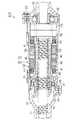
次に舵取機構200を図2を参照して説明する。図2は操舵制御装置の舵取機構200の要部拡大図を示している。
【0030】
中空円筒状の第1シャフトハウジング30と中空円筒状の第2シャフトハウジング31と、中空円筒状のモータハウジング32とは、同軸となるようにかつ一体になるように互いに連結されており、図示しない車両のボディに対して支持されている。すなわち、モータハウジング32は、前記両ラックハウジングに対して、ボルト33,34(図2参照)によって結合されている。
【0031】
第1シャフトハウジング30と第2シャフトハウジング31とモータハウジング32とから構成された筒状体内には、シャフト35が回転不能かつ軸線方向に移動可能に内蔵されている。シャフト35の両端部は図示しないタイロッドを介して左右の前輪T(操舵輪)が連結されている。なお、モータハウジング32は舵取機構200のハウジングとしても機能している。
【0032】
次に、モータハウジング32内の構成を図2及び図3を用いて説明する。
モータハウジング32内には一対のモータ(電動モータ)が設けられている。以下、それぞれ第1モータ36及び第2モータ37といい、両モータは三相同期式ブラシレスDCモータを構成する。
【0033】
第1モータ36及び第2モータ37は、互いに共通の固定子を構成するステータ38及び互いに共通のロータを構成するモータシャフト39とを有する。すなわち、両モータは同軸上に配置されている。
【0034】
そして、ステータ38には、モータハウジング32の内周に嵌合するようにして複数の突極40が互いに等角度隔てて設けられている。本実施形態では、突極40は12個設けられている。これら突極40のそれぞれに第1モータ36の第1モータ巻線41及び第2モータ37の第2モータ巻線42が絶縁ボビン44を介して巻回されている。本実施形態では、第1モータ巻線41が突極40のモータハウジング32側に配置され、第2モータ巻線42がモータシャフト39側に巻装されている(図3参照)。
【0035】
第1モータ巻線41及び第2モータ巻線42はモールド成型により絶縁性樹脂が被覆されている。
本実施形態では、第1モータ巻線41及び第2モータ巻線42は、巻装された共通の突極40が同相、同極性になるように同突極40に対して巻装されるとともに、後述する第1駆動回路55及び第2駆動回路57にてそれぞれ制御される。
【0036】
例えば、U相、V相、W相にそれぞれなる第1モータ巻線41がそれぞれ巻装された各突極40には、U相、V相、W相にそれぞれなる第2モータ巻線42がそれぞれ巻装されている。又、Uバー相、Vバー相、Wバー相にそれぞれなる第1モータ巻線41が、それぞれ巻装された各突極40には、Uバー相、Vバー相、Wバー相にそれぞれなる第2モータ巻線42がそれぞれ巻装されている。なお、「バー」が付された相は、「バー」が付されていない相とは突極40が逆の極性になるように巻装方向が逆方向になっていることを意味する。又、以下の説明では、断りがなければU相及びUバー相になる巻線を単にU相巻線ということがある。他の相についても、同様に「〜相巻線」ということがある。
【0037】
そして、各突極40に巻装された巻線は、モータの回転方向に沿って、U1,U1バー,V1,V1バー,W1,W1バー,U2,U2バー,V2,V2バー,W2,W2バーの順に配置されている。なお、U1,U2は同じ極性となるU相であり、U1バー,U2バーは同じ極性となるU相である。他のV,Wについても同じ意味である。
【0038】
又、第1モータ36及び第2モータ37は出力が同じとされている。すなわち、本実施形態では、両モータの出力を同じくするために、第1モータ巻線41及び第2モータ巻線42の各突極40に対する巻数は同じとされ、かつ、後述する第1駆動回路55及び第2駆動回路57から出力される励磁電流が同じとされている。すなわち、第1ECU21及び第2ECU22は、第1駆動回路55及び第2駆動回路57から出力される励磁電流が同じとなるように制御する。そして、両モータが同時に作動している際の両モータの合成出力トルクは、各モータの出力トルクの2倍とされている。
【0039】
第1駆動回路55は第1駆動手段に相当し、第2駆動回路57は第2駆動手段に相当する。
又、モータシャフト39は、中空円筒状であり、シャフト35の軸心方向の中間部において同軸的にシャフト35の外側に遊嵌されている。モータシャフト39は、その一端側が第1ベアリング45を介してモータハウジング32と、第1シャフトハウジング30に対して支持されている。
【0040】
モータシャフト39の他端側は、中間部分よりも拡径された中空円筒状のナット保持部47が一体に形成されている。ナット保持部47は第2ベアリング46を介してモータハウジング32と、第2シャフトハウジング31に対して自身の軸心の周りで回動自在に支持されている。
【0041】
以上により、モータシャフト39は、第1及び第2ベアリング45,46を介して第1及び第2シャフトハウジング30,31とモータハウジング32に回転可能に支持される。
【0042】
又、モータシャフト39の軸線方向の中間部分のステータ38と対向する位置には、永久磁石48が外設して一体回転可能に固定されている。そして、ステータ38の第1モータ巻線41及び第2モータ巻線42のうち少なくとも何れか一方に電流が流れると、永久磁石48を備えたモータシャフト39には軸心を中心軸とする回転力が発生し、モータシャフト39が回転するようになっている。
【0043】
又、モータシャフト39のナット保持部47内にはボールねじナット49が同軸的に内嵌されている。このボールねじナット49の内周面には螺旋状のボールねじ溝50が設けられている。
【0044】
シャフト35の外周面には軸線方向の所定範囲に螺旋状のボールねじ溝51が設けられている。そして、このボールねじ溝51と前記ボールねじ溝50との間には、図示しない多数のボールが転動可能に受容されている。このように、シャフト35のボールねじ溝51とボールねじナット49とによりボールねじ構造を備えたボールねじ機構が形成されている。
【0045】
そして、このボールねじ機構によりモータシャフト39の正逆回転の出力トルクをシャフト35の軸線方向の往復動の推力に変換する。
又、前記両モータのステータ38と第1ベアリング45との間には、第1回転角センサ52,第2回転角センサ53がモータシャフト39の軸線方向に沿って並設されている。この第1回転角センサ52,第2回転角センサ53は、ロータリーエンコーダにて構成されている。
【0046】
両回転角センサは、それぞれモータシャフト39の回転に応じてπ/2ずつ位相の異なる2相パルス列信号と基準回転位置を表す零相パルス列信号を第1ECU21及び第2ECU22に入力する。以下、各回転角センサが検出し、出力する信号を単に、検出信号(2相パルス列信号及び零相パルス列信号を含む)ということがある。
【0047】
又、第1回転角センサ52及び第2回転角センサ53からの検出信号は、所定のサンプリング周期で第1ECU21及び第2ECU22に入力されている。
そして、第1ECU21及び第2ECU22は入力された検出信号に基づいて第1モータ36及び第2モータ37におけるモータシャフト39のステータ38に対する回転角が判断できるようになっている。
【0048】
(制御部300)
次に、制御部300について説明する。
制御部300は、第1ECU21、第2ECU22、第1駆動回路55及び第2駆動回路57とを備えている。
【0049】
第1ECU21及び第2ECU22はそれぞれマイクロコンピュータを含んだ電子制御ユニットにて構成されている。
1.第1ECU21について
第1ECU21は、制御プログラムにより、演算、処理及び記憶等の各種の構成を有しており、すなわち、図5に示すように、位置制御部21A、トルク分配部21B、電流制御部21Cを備える。
【0050】
第1ECU21の制御モードは、始動時制御モード、正常時制御モードが用意されている。
(第1ECU21の始動時制御モード、及び正常時制御モード)
第1ECU21は、始動時制御モード及び正常時制御モードでは、第1操舵角センサ14が検出した操舵角に対応する転舵角(操舵輪の転舵角)が得られるように、かつ、そのためにモータシャフト39に必要な推力が得られるように第1駆動回路55を介して第1モータ36を舵取制御を実行する。
【0051】
詳説すると、位置制御部21Aは、第1操舵角センサ14が検出した操舵角を位置指令として入力するととともに、第1回転角センサ52からの検出信号を入力し、同信号に基づいてモータシャフト39のステータ38に対する回転角を算出する。第1回転角センサ52からの検出信号は電動モータの位置情報に相当する。
【0052】
位置制御部21Aは、算出した電動モータ(第1モータ36)の回転角と、位置指令としての操舵角に基づく操舵位置との偏差を演算し、その偏差に対して、位置制御に必要な所定のゲインを乗算し、その乗算値をトルク指令ΔPとしてトルク分配部21Bに供給する。
【0053】
トルク指令ΔPは位置制御による演算結果に基づいて生成された第1トルク指令に相当する。
位置制御部21Aでは、位置フィードバック制御が行われ、指令値(位置指令)とフィードバック値(第1モータ36の回転角)の偏差が0になるように制御する。
【0054】
トルク分配部21Bは、供給されたトルク指令ΔPを所定の分配比で分配し、分配したトルク指令ΔP1とトルク指令ΔP2とをそれぞれ第1システムSY1の電流制御部21Cと第2システムSY2の電流制御部22Cに供給する。
【0055】
なお、トルク分配部21Bは、操舵制御装置に含まれる両システムが正常時において、車両のエンジン始動時での分配比をエンジンの始動時以外のときの分配比と異なるようにし、その分配比を可変する。
【0056】
本実施形態では、車両のエンジン始動時(始動時制御モード)での分配比は50:0(=ΔP1:ΔP2)とされ、車両のエンジン始動時以外(正常時制御モード)の分配比は50:50(=ΔP1:ΔP2)とされている。
【0057】
第1ECU21による第1モータ36の舵取制御は、転舵角が操舵角と対応するように制御する位置制御と、そのためにモータシャフト39に必要な推力、すなわち、出力トルクを得るためのトルク制御とが含まれる。
【0058】
図6は、電流制御部21Cの制御ブロック図である。
電流制御部21Cは、トルク電流変換部61、PI制御部64,PI制御部65、d/q逆変換部66、パルス幅変調部67(PWM)、d/q変換部68、角度検出部69等を備えている。
【0059】
正常時制御モードでは、電流制御部21Cは、トルク指令ΔP1と、第1回転角センサ52の検出信号、及び後述する電流センサ71,72から、第1モータ36に対する3相の励磁電流iu,iv,iwのうちの2つの励磁電流iu,ivに係る電流検出値信号を入力する。
【0060】
すなわち、角度検出部69は、第1回転角センサ52の検出信号に基づいて回転角θを演算し、d/q変換部68に入力する。
なお、d/q変換部68には、演算器70にて励磁電流iu,ivに基づいて計算された励磁電流iw(電流検出値信号)が入力される。
【0061】
これらの励磁電流iu,iv,iwは第1モータ36の実電流に相当する。
d/q変換部68は前記電流検出値信号と、回転角θを用いてd/q変換し、電流値id,iqとする。
【0062】
なお、d/q変換とは、電動モータの回転子の磁束と同一方向をd軸とし、d軸と直交する方向をq軸とした直交座標を設定し、その直交座標に対して各相に流れる交流電流のベクトルを写像することにより、交流を直流に変換する公知の手法である。
【0063】
又、トルク電流変換部61は前記トルク指令ΔP1をq軸電流指令値iq*に変換する。偏差演算部63はq軸電流指令値iq*とd/q変換部68からの電流値iqとの偏差ΔIqを演算する。
【0064】
一方、偏差演算部62はd軸電流指令値id*と、d/q変換部68からの電流値idとの偏差ΔIdを演算する。なお、ブラシレスDCモータは回転子がマグネットであり、励磁電流を流す必要がないことから、d軸電流指令値id*=0である。
【0065】
PI制御部64は偏差ΔIdを入力し、比例積分するとともに、電圧方程式を用いて、d軸電圧指令値Vd*を演算する。PI制御部65は偏差ΔIqを入力し、比例積分するとともに、電圧方程式を用いて、q軸電圧指令値Vq*を演算する。
【0066】
d/q逆変換部66はd軸電圧指令値Vd*及びq軸電圧指令値Vq*を入力し、電圧指令値Vu*,Vv*,Vw*を演算する。そして、パルス幅変調部67は電圧指令値Vu*,Vv*,Vw*を入力し、それぞれ対応するパルス幅を有するパルス信号(PWM制御信号)を第1駆動回路55へ出力する。第1駆動回路55は、それらのパルス信号(PWM制御信号)に基づいて第1モータ36の各相へ駆動電圧を印加する。
【0067】
以上のようにして、電流制御部21Cでは、電流のフィードバック制御(以下、電流フィードバック制御という)が行われ、指令値(トルク指令ΔP1)とフィードバック値(第1モータ36の電流値iq及び電流値id)の偏差が0になるように制御する。
【0068】
前記電流制御は、トルク制御に相当する。
(第1システムSY1のフェィル時)
第1システムSY1がフェィル時には、図7に示すように第1システムSY1の第1ECU21は、第1モータ36の制御を停止する。
【0069】
2.第2ECU22について
第2ECU22は、マイクロコンピュータを基本にして演算、処理及び記憶等の各種機能から構成され、始動時制御モード、正常時制御モードと、フェィル時制御モードを実行する。
【0070】
第2ECU22は、始動時制御モード及び正常時制御モードでは、図5に示すように電流制御部22Cを備え、フェィル時制御モードでは、図7に示すように、位置制御部22A、電流制御部22Cを備える。
【0071】
(第2ECU22の始動時制御モード及び正常時制御モード)
始動時制御モード及び正常時制御モードでは、図5に示すように電流制御部22Cは、トルク指令ΔP2と、第2回転角センサ53の検出信号、及び後述する電流センサ71,72から、第2モータ37に対する3相の励磁電流iu,iv,iwのうちの2つの励磁電流iu,ivに係る電流検出値信号を入力する。
【0072】
なお、電流制御部22Cでは、図6に示す電流制御部21Cと同様に、トルク電流変換部、一対のPI制御部、d/q逆変換部、パルス幅変調部、d/q変換部、角度検出部等を備えている。
【0073】
正常時制御モードでの電流制御部22Cは、電流制御部21Cと同様の構成のため、図6で示す電流制御部21Cの構成と同一構成又は相当する構成については、同一符号を付してその説明を省略する。
【0074】
これらの各部は、電流制御部21Cの各部と同様にトルク指令ΔP2、第2回転角センサ53の検出信号、及び後述する電流センサ71,72からの励磁電流iu,ivに係る電流検出値信号を処理する。この処理により、第2ECU22からは、パルス信号(PWM制御信号)を第2駆動回路57へ出力する。第2駆動回路57は、それらのパルス信号(PWM制御信号)に基づいて第2モータ37の各相へ駆動電圧を印加する。
【0075】
以上のようにして、電流制御部22Cでは、電流フィードバック制御が行われ、指令値(トルク指令ΔP2)とフィードバック値(第2モータ37の電流値iq及び電流値id)の偏差が0になるように制御する。
【0076】
前記電流制御は、トルク制御に相当する。
なお、始動時制御モードでは、トルク分配部21Bは分配比を50:0(=ΔP1:ΔP2)としているため、電流制御部22Cに入力されるトルク指令ΔP2は0である。従って、第2ECU22は、実際には、第2モータ37を駆動制御することはない。
【0077】
(第2ECU22のフェィル時制御モード)
フェィル時制御モードにおける、第2ECU22による第2モータ37の舵取制御は、転舵角が操舵角と対応するように制御する位置制御と、そのためにモータシャフト39に必要な推力、すなわち、出力トルクを得るためのトルク制御とが含まれる。
【0078】
すなわち、フェィル時制御モードでは、第2ECU22は、第2操舵角センサ15が検出した操舵角に対応する転舵角(操舵輪の転舵角)が得られるように、かつ、そのためにモータシャフト39に必要な推力が得られるように第2駆動回路57を介して第2モータ37を舵取制御を実行する。
【0079】
詳説すると、位置制御部22Aは、第2操舵角センサ15が検出した操舵角を位置指令として入力するととともに第2回転角センサ53からの検出信号を入力し、同信号に基づいてモータシャフト39のステータ38に対する回転角を算出する。
【0080】
第2回転角センサ53からの検出信号は第2モータ37(電動モータ)の位置情報に相当する。
位置制御部22Aは、算出した電動モータ(第2モータ37)の回転角と、位置指令としての操舵角に基づく操舵位置との偏差を演算し、その偏差に対して、位置制御に必要な所定のゲインを乗算し、その乗算値をトルク指令ΔP3として電流制御部22Cに供給する。
【0081】
トルク指令ΔP3は第2トルク指令に相当する。
位置制御部22Aでは、位置制御が行われ、指令値(位置指令)及びフィードバック値(第2モータ37の回転角)の偏差が0になるように制御する。
【0082】
又、トルク指令ΔP3は下記のように設定されている。
すなわち、車両走行中は路面反力が小さいことから、車両走行中において第2モータ37のみでモータシャフト39を駆動した場合に得られる推力(出力トルク)による転舵範囲が、操舵制御装置に含まれる両システムの正常時に得られる転舵範囲と同じになるように、トルク指令ΔP3は設定されている。
【0083】
なお、車両が走行停止した場合において、据え切り操舵を行ったときには、路面反力が大きいため、前記トルク指令ΔP3に基づいた第2モータ37のみの推力では、操舵制御装置に含まれる両システムが正常時よりも範囲が狭まった転舵範囲が得られるものとされている。
【0084】
本実施形態では、トルク指令ΔP3は正常時制御モードでのトルク指令ΔP2と同じ値とされている。
フェィル時制御モードでの、電流制御部22Cは、正常時制御モードでの電流制御部21Cと同様の構成であるため、図6で示す電流制御部21Cの構成と同一構成又は相当する構成については、同一符号を付してその説明を省略する。
【0085】
なお、本実施形態では、電流制御部22CのPI制御部64,PI制御部65では、正常時制御モードのときと電流ループゲインが異なるようにされている。なお、電流ループゲインは、PI制御部64,PI制御部65における積分ゲイン及び比例ゲインのことである。フェィル時制御モードでのこれらのゲインは、正常時制御モードのこれらのゲインよりも大きく設定されている。
【0086】
フェィル時制御モードでの電流ループゲインが正常時制御モードの電流ループゲインよりも大きくされていることにより、ステアリングホイール10の操作に対する応答性の低下が生ぜず、又、ステアリングホイール10の操作への追従性が低下しないようにされている。
【0087】
電流制御部22Cの各部は、トルク指令ΔP3、第2回転角センサ53の検出信号、及び後述する電流センサ71,72からの励磁電流iu,ivに係る電流検出値信号を処理する。この処理により、第2ECU22からは、パルス信号(PWM制御信号)を第2駆動回路57へ出力する。第2駆動回路57は、それらのパルス信号(PWM制御信号)に基づいて第2モータ37の各相へ駆動電圧を印加する。
【0088】
以上のようにして、フェィル時制御モードにおいて、電流制御部22Cでは、電流制御が行われ、指令値(トルク指令ΔP3)及びフィードバック値(第2モータ37の電流値iq及び電流値id)の偏差が0になるように制御する。
【0089】
前記電流制御は、トルク制御に相当する。
(第1駆動回路55、第2駆動回路57)
上記のように本実施形態の操舵制御装置は、2つのシステムを備えた冗長な構成とされている。
【0090】
1つのシステム、すなわち第1システムSY1は、第1ECU21、第1操舵角センサ14、第1駆動回路55及び第1モータ36などから構成されている。他の残りのシステム、すなわち他の1つのシステム(第2システムSY2)は、第2ECU22、第2操舵角センサ15、第2駆動回路57及び第2モータ37などから構成されている。
【0091】
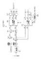
ここで、第1駆動回路55の構成及びその周辺回路の詳細を図4を参照して説明する。図4は第1駆動回路55及びその周辺回路の電気回路図である。
なお、第2駆動回路57及びその周辺回路は第1駆動回路55及びその周辺回路と同じ構成であるため、第2駆動回路57及びその周辺回路の説明は省略する。この代わりに、図4中には、括弧内に、第2駆動回路57及びその周辺回路の符号を、第1駆動回路55とその周辺回路の説明した構成に対応して付するものとする。
【0092】
第1駆動回路55は、FET(Field-Effect Transistor) 81U,82Uの直列回路と、FET81V,82Vの直列回路と、FET81W,82Wの直列回路とを並列に接続して構成されている。各直列回路には、車両に搭載されたバッテリB、あるいは発電機の電圧が印加されている。図1及び図4では、各直列回路はバッテリBに接続されていることが図示されている。そして、FET81U,82U間の接続点83Uが第1モータ巻線41のU相巻線に接続され、FET81V,82V間の接続点83Vが第1モータ巻線41のV相巻線に接続され、FET81W,82W間の接続点83Wが第1モータ巻線41のW相巻線に接続されている。
【0093】
3相の励磁電流路のうちの2つには電流センサ71,72が設けられ、各電流センサ71,72は、第1モータ36に対する3相の励磁電流iu,iv,iwのうちの2つの励磁電流iu,ivを検出して第1ECU21に出力する。
【0094】
FET81U,82U、FET81V,82V及びFET81W,82Wには、第1ECU21からPWM制御信号が入力される。
第1駆動回路55は、PWM制御信号に対応した3相の励磁電流を発生して、3相の励磁電流路を介して第1モータ36にそれぞれ供給する。
【0095】
図1、図4において、バッテリB(又は発電機)と直列回路印加点Q1との間に、電源リレー90が設けられている。電源リレー90は常閉リレー接点であって、第2ECU22の制御信号により、オフする。
【0096】
さらに、第1駆動回路55のFET81UとFET82Uの接続点83Uと、第1モータ36のU相巻線の接続点間には,相開放リレー210が設けられている。又、第1駆動回路55のFET81WとFET82Wの接続点83Wと、第1モータ36のW相巻線の接続点間には,相開放リレー220が設けられている。相開放リレー210,220は、常閉リレー接点であって、第2ECU22の制御信号により、オフする。
【0097】
又、第1ECU21及び第2ECU22は、自らが演算した第1モータ36及び第2モータ37のそれぞれの実際の回転角や、自身のシステムのセンサ類の検出値や、モータ制御に必要な他の情報及びエラー情報(異常判定信号)を常に相互に通信して交換する相互監視機能(ウォッチ・ドッグ機能)を備える。例えば、共通のモータシャフト39であるため、両ECUがそれぞれ演算したモータシャフト39の回転角が一致したとき、各ECUはそれぞれ他のECUが正常であると判定し、異常であれば、エラー情報(異常判定信号)を他のECUに通信する。なお、以下の説明では、エラー情報は、第1ECU21から第2ECU22へのものは、α12とし、第2ECU22から第1ECUへのものはα21としている。
【0098】
そして、1つのシステムが、他のシステムに関して異常であると判定すると、同1つのシステムは他のシステムの電源リレー90、相開放リレー210、相開放リレー220をオフする。
【0099】
このように第1ECU21、第2ECU22はそれぞれ第1システムSY1及び第2システムSY2の制御手段及び故障検出手段に相当する。
(第1実施形態の作用)
さて、上記のように構成された、操舵制御装置の作用を説明する。
【0100】
図8は、第1ECU21が所定周期毎に実行する舵取制御の制御プログラムのフローチャートである。
S10では、図示しないエンジンが始動されたか、或いは始動後か否かを判定する。この判定は、図示しないイグニッションスイッチのオン信号の入力が第1システムSY1の第1ECU21にあったか否か、すなわち、前記オン信号の立ち上がりエッジの発生があってから、所定時間内か否かにより判定する。エンジンが始動された場合には、S20において、第1ECU21は始動時制御モードに入り、このステップを一旦終了する。
【0101】
従って、イグニッションスイッチのオン信号の入力から所定時間内は第1システムSY1の第1ECU21は始動時制御モードとなる。又、第2システムSY2の第2ECU22は、第1ECU21からのトルク指令ΔP2の入力により、始動時制御モードとなる。
【0102】
イグニッションスイッチのオン信号の入力から所定時間を経過した場合には、S10の判定は「NO」となり、S30において、第1システムSY1が異常状態となっていないか否かを判定する。
【0103】
この判定は、第2ECU22からのエラー情報α21(異常判定信号)に基づいて判定する。
なお、第2ECU22と第1ECU21は、図示しない通信回線にて連結されており、第1ECU21から入力される演算した第1モータ36の実際の回転角、自身のシステムのセンサ類の検出値やモータ制御に必要な他の情報に基づいて第1システムSY1が異常か否かを判定している。
【0104】
第1システムSY1の異常にはセンサ類(第1操舵角センサ14)の異常、第1ECU21の異常、第1駆動回路55の異常等、第1システムSY1を構築する各構成の異常が含まれる。
【0105】
S30において、第2ECU22からのエラー情報α21(異常判定信号)に基づいて、第1システムSY1は正常であると判定すると、S40において、正常時制御モードの処理を実行し、一旦この処理を終了する。S40では、それぞれのシステムにおいて、第1モータ36及び第2モータ37は、分配されたトルク指令ΔP1と、トルク指令ΔP2に基づいて同時に駆動される。
【0106】
一方、第2システムSY2では、第1ECU21の正常時制御モードによる第1ECU21からのトルク指令ΔP2の入力があることにより、正常時制御モードとなる。
【0107】
S30において、第2ECU22からエラー情報α21に基づいて第1システムSY1が異常であると判定すると、S50において、フェィル時処理を実行し、このフローチャートを終了する。フェィル時処理とは、第1駆動回路55へのPWM制御信号の入力を停止することである。又、第2ECU22は、エラー情報α21の出力と同時に第1システムSY1の電源リレー90及び相開放リレー210,220をオフする。
【0108】
この結果、第1モータ36の第1モータ巻線41への励磁電流の供給が絶たれる。このとき、第1モータ36の分の推力(出力トルク)はなくなる。
一方、第2システムSY2の第2ECU22は、エラー情報α21の出力を行うと、フェィル時制御モードに入る。
【0109】
このとき、第2システムSY2の第2モータ37は継続して駆動されているため、モータシャフト39の推力(出力トルク)は半分になる。なお、このように他のシステムが異常になった際にも、残りのシステムの第2ECU22は、正常時の出力トルク(出力)と同じ出力トルク(出力)となるように制御する。
【0110】
しかし、車両が走行中においては、正常時のモータシャフト39の推力(出力トルク)の半分の推力(出力トルク)であっても、十分に前輪T(操舵輪)の転舵が可能である。
【0111】
又、第1システムSY1では相開放リレー210,220がオフされているため、第1モータ36では発電することがなく、第2モータ37の推力を減殺する発電制動が生ずることはない。
【0112】
本実施形態によれば、以下のような特徴を得ることができる。
(1) 本実施形態の操舵制御装置では、舵取機構200の前輪T(操舵輪)上に同軸形状に一体配置された2個の概同一性能の第1モータ36,第2モータ37と、各モータを制御する第1ECU21及び第2ECU22(制御手段)を含む複数のシステムを備えた。そして、各システムのモータを同時に制御して共通の舵取機構200を駆動するようにした。
【0113】
又、第1システムSY1の第1ECU21は、ステアリングホイール10(操舵ハンドル)の操舵位置と自身のシステムのモータの位置情報に基づいて舵取機構200を駆動するために必要となるトルク指令ΔP(第1トルク指令)を生成し、トルク指令ΔPをシステムの数に応じて分配した。そして、第1ECU21は分配後の自身のシステム用のトルク指令ΔP1に基づいてモータに対してトルク制御を行うようにした。さらに、他のシステムの第2ECU22(制御手段)は、当該システムに分配されたトルク指令ΔP2に基づいて当該システムのモータに対してトルク制御を行うようにした。
【0114】
このように、1つのシステムが、上位制御ループ(位置制御)を統括して、操舵制御装置全体に必要なトルクを算出し、それを他のシステムにトルク指令として分配して、各システムは各自でトルク制御(下位制御ループ)を行うようにした。
【0115】
この結果、2つのシステムの各モータを同時駆動する際、位置制御を第1システムSY1でのみ行っているため、両モータのトルク干渉の問題はなく、トルク干渉に起因したトルクの低下を生ずることがない。そして、トルクの低下が生ずることがないため、ステアリングホイール10の操作に対する応答性の低下が生ぜず、ステアリングホイール10の操作への追従性が低下することもない。
【0116】
又、トルク干渉がないため、異音、振動、発熱の発生を抑えることができる効果を奏する。
図9は従来の構成の参考例である。
【0117】
この場合、第1システムSY1において、位置制御部21A、電流制御部21Cを備え、第2システムSY2において、位置制御部22A、電流制御部22Cを備えた場合を示している。なお、図9においては、説明の便宜上、各部には本実施形態の構成に相当する部分については、同一符号を付して、その説明を省略する。
【0118】
このように構成した場合には、各システムにおいて、第1モータ36、第2モータ37に設けた第1回転角センサ52、第2回転角センサ53による各モータの回転角に基づいて位置フィードバック制御が行われる。しかし、各モータの組付誤差や、第1回転角センサ52,第2回転角センサ53の組付誤差などにより、各モータは異なった位置に制御されてしまい、発生トルクの方向が合わずにトルクが低下したり、異音や振動が発生したり、さらには電動モータが発熱してしまう問題がある。
【0119】
第1実施形態では、このようなことはない。
(2) 第1実施形態では、第1ECU21、及び第2ECU22はそれぞれ自身のシステム以外の他のシステムの故障検出を行う故障検出手段とした。そして、トルク指令ΔP10を生成していた第1システムSY1が故障した場合、第2システムSY2の第2ECU22(制御手段)は、ステアリングホイール10の操舵位置と自身のシステムのモータの位置情報に基づいてトルク指令ΔP3(第2トルク指令)を生成した。
【0120】
そして、トルク指令ΔP3(第2トルク指令)を正常なシステムの数(第1実施形態では1つ)に応じて分配し、分配後の自身のシステム用のトルク指令ΔP3に基づいてモータに対してトルク制御を行うようにした。
【0121】
この結果、第1システムSY1が故障した場合でも、第2システムSY2が第2モータ37を駆動制御することができ、バックアップすることができる。
このように、1つのシステムが故障した場合、故障したシステムの中に上位制御ループ(位置制御)を統括していたシステムが含まれている場合、他の正常なシステムの1つが上位制御ループを新たに統括し、改めて算出された全体必要トルクを正常なシステムの数に応じて分配するようにした。
【0122】
そして、複数の概同一性能のモータが同軸上に一体に配置されていることにより、モータ性能差による制約がないため、故障時のトルクの分配が容易となり、性能低下も防ぐことができる。
【0123】
(3) 第1実施形態は、第1システムSY1が故障した場合、第2システムSY2の電流制御部22Cは正常時制御モードの場合よりもその電流ループゲインを大きくし、第1システムSY1が故障した時のステアリングホイール10の操作に対する応答性の低下を補うようにした。
【0124】
この結果、第1システムSY1が故障した場合には、ステアリングホイール10の操作に対する応答性の低下を抑制できる効果がある。
(第2実施形態)
次に第2実施形態を図10及び図11を参照して説明する。
【0125】
本実施形態の操舵制御装置のハード構成は、第1実施形態と同じ構成であるため、第1実施形態と同一構成又は相当する構成については、同一符号を付してその説明を省略し、異なるところを中心に説明する。
【0126】
第1実施形態では、位置フィードバック制御、電流フィードバック制御を実行するようにしたが、本実施形態では、位置フィードバック、電流フィードバック制御の他にさらに速度フィードバック制御を行うところが異なっている。
【0127】
(第1ECU21の始動時制御モード、及び正常時制御モード)
図10の一点鎖線内は、第1システムSY1の正常時制御モードにおける第1ECU21及び第2ECU22の制御ブロックの構成を示している。
【0128】
第1ECU21は、始動時制御モード及び正常時制御モードでは、第1操舵角センサ14が検出した操舵角に対応する転舵角(操舵輪の転舵角)が得られるように、かつ、そのためにモータシャフト39に必要な推力が得られるように第1駆動回路55を介して第1モータ36の舵取制御を実行する。
【0129】
詳説すると、位置制御部21Aは、第1操舵角センサ14が検出した操舵角を位置指令として入力するととともに、第1回転角センサ52からの検出信号を入力し、同信号に基づいてモータシャフト39のステータ38に対する回転角を算出する。第1回転角センサ52からの検出信号は電動モータの位置情報に相当する。
【0130】
位置制御部21Aは、算出した電動モータ(第1モータ36)の回転角と、位置指令としての操舵角に基づく操舵位置との偏差を演算し、その偏差に対して、位置制御に必要な所定のゲインを乗算し、その乗算値を速度指令C1として速度制御部21Dに供給する。
【0131】
微分処理部21Eは、第1回転角センサ52からの検出信号を入力して同信号に基づいてモータ速度を算出し、速度制御部21Dにその算出値を入力する。
速度制御部21Dは、速度指令C1と、モータ速度との偏差を演算し、その偏差に対して、速度制御に必要な所定のゲインを乗算し、その乗算値をトルク指令ΔP10としてトルク分配部21Bに供給する。
【0132】
トルク指令ΔP10は速度制御による演算結果に基づいて生成された第1トルク指令に相当する。
トルク分配部21Bは、供給されたトルク指令ΔP10を所定の分配比で分配し、分配したトルク指令ΔP11とトルク指令ΔP12とをそれぞれ第1システムSY1の電流制御部21Cと第2システムSY2の電流制御部22Cに供給する。
【0133】
本実施形態においても、第1実施形態と同様にトルク分配部21Bは、操舵制御装置に含まれる両システムが正常時において、車両のエンジン始動時での分配比をエンジンの始動時以外のときの分配比と異なるようにし、その分配比を可変する。
【0134】
すなわち、車両のエンジン始動時(始動時制御モード)での分配比は50:0(=ΔP11:ΔP12)とされ、車両のエンジン始動時以外(正常時制御モード)の分配比は50:50(=ΔP11:ΔP12)とされている。
【0135】
第1ECU21による第1モータ36の舵取制御は、転舵角が操舵角と対応するように制御する位置制御と、速度指令C1にモータ速度が対応するように制御する速度制御と、そのためにモータシャフト39に必要な推力、すなわち、出力トルクを得るためのトルク制御とが含まれる。
【0136】
電流制御部21Cの構成は、第1実施形態と同様の構成であるため、説明を省略する。
従って、電流制御部21Cでは、電流フィードバック制御が行われ、指令値(トルク指令ΔP11)とフィードバック値(第1モータ36の電流値iq及び電流値id)の偏差が0になるように制御する。
【0137】
前記電流制御は、トルク制御に相当する。
(第1システムSY1のフェィル時)
第1システムSY1がフェィル時には、図11に示すように第1システムSY1の第1ECU21は、第1モータ36の制御を停止する。
【0138】
1.第2ECU22について
第2ECU22は、マイクロコンピュータを基本にして演算、処理及び記憶等の各種機能から構成され、始動時制御モード、正常時制御モードと、フェィル時制御モードを実行する。
【0139】
第2ECU22は、始動時制御モード及び正常時制御モードでは、図10に示すように電流制御部22Cを備え、フェィル時制御モードでは、図11に示すように、位置制御部22A、電流制御部22C、速度制御部22D、微分処理部22Eを備える。
【0140】
(第2ECU22の始動時制御モード及び正常時制御モード)
始動時制御モード及び正常時制御モードでは、図10に示すように電流制御部22Cは、トルク指令ΔP12と、第2回転角センサ53の検出信号、及び電流センサ71,72から、第2モータ37に対する3相の励磁電流iu,iv,iwのうちの2つの励磁電流iu,ivに係る電流検出値信号を入力する。
【0141】
なお、電流制御部22Cでは、電流制御部21Cと同様に、トルク電流変換部、一対のPI制御部、d/q逆変換部、パルス幅変調部、d/q変換部、角度検出部等を備えている。
【0142】
正常時制御モードでの電流制御部22Cは、電流制御部21Cと同様の構成のため、電流制御部21Cの構成と同一構成又は相当する構成については、同一符号を付してその説明を省略する。
【0143】
これらの各部は、電流制御部21Cの各部と同様にトルク指令ΔP12、第2回転角センサ53の検出信号、及び後述する電流センサ71,72からの励磁電流iu,ivに係る電流検出値信号を処理する。この処理により、第2ECU22からは、パルス信号(PWM制御信号)を第2駆動回路57へ出力する。第2駆動回路57は、それらのパルス信号(PWM制御信号)に基づいて第2モータ37の各相へ駆動電圧を印加する。
【0144】
以上のようにして、電流制御部22Cでは、電流フィードバック制御が行われ、指令値(トルク指令ΔP12)とフィードバック値(第2モータ37の電流値iq及び電流値id)の偏差が0になるように制御する。
【0145】
前記電流制御は、トルク制御に相当する。
なお、始動時制御モードでは、トルク分配部21Bは分配比を50:0(=ΔP11:ΔP12)としているため、電流制御部22Cに入力されるトルク指令ΔP12は0である。従って、第2ECU22は、実際には、第2モータ37を駆動制御することはない。
【0146】
(第2ECU22のフェィル時制御モード)
フェィル時制御モードにおける、第2ECU22による第2モータ37の舵取制御は、転舵角が操舵角と対応するように制御する位置制御と、速度指令C2にモータ速度が対応するように制御する速度制御と、そのためにモータシャフト39に必要な推力である出力トルクを得るためのトルク制御とが含まれる。
【0147】
フェィル時制御モードでは、第2ECU22は、第2操舵角センサ15が検出した操舵角に対応する転舵角(操舵輪の転舵角)が得られるように、かつ、そのためにモータシャフト39に必要な推力が得られるように第2駆動回路57を介して第2モータ37の舵取制御を実行する。
【0148】
詳説すると、位置制御部22Aは、第2操舵角センサ15が検出した操舵角を位置指令として入力するととともに第2回転角センサ53からの検出信号を入力し、同信号に基づいてモータシャフト39のステータ38に対する回転角を算出する。
【0149】
第2回転角センサ53からの検出信号は第2モータ37(電動モータ)の位置情報に相当する。
位置制御部22Aは、算出した電動モータ(第2モータ37)の回転角と、位置指令としての操舵角に基づく操舵位置との偏差を演算し、その偏差に対して、位置制御に必要な所定のゲインを乗算し、その乗算値を速度指令C2として速度制御部22Dに供給する。
【0150】
微分処理部22Eは、第2回転角センサ53からの検出信号を入力して同信号に基づいてモータ速度を算出し、速度制御部22Dにその算出値を入力する。
速度制御部22Dは、速度指令C2と、モータ速度との偏差を演算し、その偏差に対して、速度制御に必要な所定のゲインを乗算し、その乗算値をトルク指令ΔP13として電流制御部22Cに供給する。
【0151】
トルク指令ΔP13は速度制御による演算結果に基づいて生成された第2トルク指令に相当する。
速度制御部22Dでは、速度制御が行われ、指令値(速度指令C2)及びフィードバック値(第2モータ37のモータ速度)の偏差が0になるように制御する。
【0152】
又、トルク指令ΔP13は下記のように設定されている。
すなわち、車両走行中は路面反力が小さいことから、車両走行中において第2モータ37のみでモータシャフト39を駆動した場合に得られる推力(出力トルク)による転舵範囲が、操舵制御装置に含まれる両システムの正常時に得られる転舵範囲と同じになるように、トルク指令ΔP13は設定されている。
【0153】
なお、車両が走行停止した場合において、据え切り操舵を行ったときには、路面反力が大きいため、前記トルク指令ΔP13は、第2モータ37のみでの推力では、操舵制御装置に含まれる両システムが正常時よりも範囲が狭まった転舵範囲が得られるものに設定されている。
【0154】
本実施形態では、トルク指令ΔP13は正常時制御モードでのトルク指令ΔP12と同じ値とされている。
フェィル時制御モードでの、電流制御部22Cは、正常時制御モードでの電流制御部21Cと同様の構成であるため、図6で示す電流制御部21Cの構成と同一構成又は相当する構成については、同一符号を付してその説明を省略する。
【0155】
なお、本実施形態では、電流制御部22CのPI制御部64,PI制御部65では、正常時制御モードのときと電流ループゲインが異なるようにされている。なお、電流ループゲインは、PI制御部64,PI制御部65における積分ゲイン及び比例ゲインのことである。フェィル時制御モードでのこれらのゲインは、正常時制御モードのこれらのゲインよりも大きく設定されている。
【0156】
フェィル時制御モードでの電流ループゲインが正常時制御モードの電流ループゲインよりも大きくされていることにより、ステアリングホイール10の操作に対する応答性の低下が生ぜず、又、ステアリングホイール10の操作への追従性が低下しないようにされている。
【0157】
電流制御部22Cの各部は、トルク指令ΔP13、第2回転角センサ53の検出信号、及び電流センサ71,72からの励磁電流iu,ivに係る電流検出値信号を処理する。この処理により、第2ECU22からは、パルス信号(PWM制御信号)を第2駆動回路57へ出力する。第2駆動回路57は、それらのパルス信号(PWM制御信号)に基づいて第2モータ37の各相へ駆動電圧を印加する。
【0158】
以上のようにして、フェィル時制御モードにおいて、電流制御部22Cでは、電流制御が行われ、指令値(トルク指令ΔP13)及びフィードバック値(第2モータ37の電流値iq及び電流値id)の偏差が0になるように制御する。
【0159】
前記電流制御は、トルク制御に相当する。
第2実施形態においても、第1ECU21、第2ECU22はそれぞれ第1システムSY1及び第2システムSY2の制御手段及び故障検出手段に相当する。
【0160】
(第2実施形態の作用)
第2実施形態においても、第1実施形態と同様に第1ECU21は図8に示す舵取制御の制御プログラムのフローチャートを所定周期毎に実行する。このとき、第2ECU22は、第1実施形態と同様に作動する。
【0161】
従って、第2実施形態によれば、以下のような特徴を得ることができる。
(1) 第2実施形態の操舵制御装置では、正常時制御モードにおいて、第1システムSY1の第1ECU21(制御手段)は、ステアリングホイール10(操舵ハンドル)の操舵位置と第1モータ36の位置情報に基づいて位置制御を行うようにした。さらに、第1ECU21は、指令値(速度指令C2)及びフィードバック値(第2モータ37のモータ速度)に基づいて速度制御を行うようにした。
【0162】
併せて、第1ECU21(制御手段)は、速度制御による演算結果に基づいてトルク指令ΔP10(第1トルク指令)を生成し、トルク指令ΔP10をシステムの数に応じて分配した。そして、第1ECU21は、分配後の自身のシステム用のトルク指令ΔP11及び自身のシステムの第1モータ36の実電流(励磁電流iu,iv,iw)に基づいて第1モータ36に対してトルク制御を行うようにした。
【0163】
又、第2システムSY2の第2ECU22(制御手段)は、正常時制御モードにおいて、第2システムSY2に分配されたトルク指令ΔP12及び第2モータ37の実電流(励磁電流iu,iv,iw)に基づいて第2システムSY2の第2モータ37に対してトルク制御を行うようにした。
【0164】
このように、1つのシステムが、上位制御ループ(位置制御や速度制御)を統括して、操舵制御装置全体に必要なトルクを算出し、それを他のシステムにトルク指令として分配して、各システムは各自でトルク制御(下位制御ループ)を行うようにした。
【0165】
この結果、第1実施形態と同様に、2つのシステムの各モータを同時駆動する際、位置制御を第1システムSY1でのみ行っているため、両モータのトルク干渉の問題はなく、トルク干渉に起因したトルクの低下を生ずることがない。そして、トルクの低下が生ずることがないため、ステアリングホイール10の操作に対する応答性の低下が生ぜず、ステアリングホイール10の操作への追従性が低下することもない。
【0166】
又、トルク干渉がないため、異音、振動、発熱の発生を抑えることができる効果を奏する。
図18は従来の構成の参考例である。
【0167】
この場合、第1システムSY1において、位置制御部21A、速度制御部21D、電流制御部21Cを備え、第2システムSY2において、位置制御部22A、速度制御部22D、電流制御部22Cを備えた場合を示している。なお、図18においては、説明の便宜上、各部には本実施形態に構成に相当する部分については、同一符号を付して、その説明を省略する。
【0168】
このように構成すると、各システムにおいて、第1モータ36、第2モータ37に設けた第1回転角センサ52、第2回転角センサ53による各モータの回転角に基づいて位置フィードバック制御が行われる。しかし、各モータの組付誤差や、第1回転角センサ52,第2回転角センサ53の組付誤差などにより、各モータは異なった位置に制御されてしまい、発生トルクの方向が合わずにトルクが低下したり、異音や振動が発生したり、さらには電動モータが発熱してしまう問題がある。
【0169】
本実施形態では、このようなことはない。
(2) 第2実施形態では、第1システムSY1が故障した場合には、第2システムSY2の第2ECU22(制御手段)は、ステアリングホイール10(操舵ハンドル)の操舵位置と第2システムSY2の第2モータ37の位置情報に基づいて位置制御を行うようにした。さらに、第2ECU22は、同位置制御による演算結果に基づいて指令値(速度指令C1)を生成し、指令値(速度指令C1)及びフィードバック値(第2モータ37のモータ速度)に基づいて速度制御を行うようにした。
【0170】
さらに、第2ECU22は同速度制御による演算結果に基づいてトルク指令ΔP13(第2トルク指令)を生成し、トルク指令ΔP13(第2トルク指令)及び第2システムSY2の第2モータ37の実電流(励磁電流iu,iv,iw)に基づいて第2モータ37に対してトルク制御を行うようにした。
【0171】
この結果、第1システムSY1が故障した場合でも、第2システムSY2が第2モータ37を駆動制御することができ、バックアップすることができる。
このように、1つのシステムが故障した場合、故障したシステムの中に上位制御ループ(位置制御や速度制御)を統括していたシステムが含まれている場合、他の正常なシステムの1つが上位制御ループを新たに統括し、改めて算出された全体必要トルクを正常なシステムの数に応じて分配するようにした。
【0172】
そして、複数の概同一性能のモータが同軸上に一体に配置されていることにより、モータ性能差による制約がないため、故障時のトルクの分配が容易となり、性能低下も防ぐことができる。
【0173】
(3) 第2実施形態は、第1システムSY1が故障した場合、第2システムSY2の電流制御部22Cは正常時制御モードの場合よりもその電流ループゲインを大きく(可変)し、第1システムSY1が故障した時のステアリングホイール10の操作に対する応答性の低下を補うようにした。
【0174】
この結果、第1システムSY1が故障した場合には、ステアリングホイール10の操作に対する応答性の低下を抑制できる効果がある。
(第3実施形態)
次に第3実施形態を図12乃至図17を参照して説明する。
【0175】
第3実施形態の操舵制御装置のハード構成中、第2実施形態と同一構成又は相当する構成については、同一符号を付してその説明を省略し、異なるところを中心に説明する。
【0176】
図12は第3実施形態の操舵制御装置の概念図を示している。
操舵制御装置は、ステアリングホイール10(操舵ハンドル)を含む操作機構100と、車両舵取機構としての舵取機構200と、制御部300を備えている。
【0177】
(操作機構100)
回転軸11には第1操舵角センサ14及び第2操舵角センサ15の他に回転軸11の回転角に対応するステアリングホイール10の操舵角を検出する第3操舵角センサ16がさらに設けられているところが第2実施形態と異なっている。
【0178】
第3操舵角センサ16は、第3ECU23に電気的に接続されている。
(舵取機構200)
舵取機構200は図12に示すように第1モータ36及び第2モータ37の他に、前記両モータと同軸上に第3モータ43を備えているところが、第2実施形態と異なっている。
【0179】
すなわち、第3実施形態では、第1モータ36、第2モータ37、及び第3モータ43は、互いに共通の固定子を構成するステータ及び互いに共通のロータを構成するモータシャフト39とを有しており、全モータは同軸上に配置されている。この結果、第3モータ43は第1モータ36及び第2モータ37と同軸形状に一体配置され、各モータは概同一性能の三相同期式ブラシレスDCモータを構成する。第3モータ43は第3駆動回路58にて制御される。
【0180】
第1駆動回路55は第1駆動手段に相当し、第2駆動回路57は第2駆動手段に相当し、第3駆動回路は、第3駆動手段に相当する。
又、第3実施形態では、図12に示すように第1回転角センサ52,第2回転角センサ53の他に第3回転角センサ54がモータシャフト39の軸線方向に沿って並設されている。第1回転角センサ52,第2回転角センサ53及び第3回転角センサ54は、ロータリーエンコーダにて構成されている。
【0181】
又、第1回転角センサ52、第2回転角センサ53及び第3回転角センサ54の検出信号は、所定のサンプリング周期で第1ECU21、第2ECU22及び第3ECU23にそれぞれ入力されている。
【0182】
そして、第1ECU21、第2ECU22及び第3ECU23は入力された検出信号に基づいて第1モータ36、第2モータ37、及び第3モータ43におけるモータシャフト39のステータに対する回転角が判断できるようになっている。
【0183】
(制御部300)
次に、制御部300について説明する。
第3実施形態の制御部300は、第1ECU21、第2ECU22、第3ECU23、第1駆動回路55、第2駆動回路57、第3駆動回路58とを備えている。
【0184】
第1ECU21、第2ECU22、第3ECU23はそれぞれマイクロコンピュータを含んだ電子制御ユニットにて構成されている。
なお、第3ECU23のハード構成は、第2実施形態の第1ECU21、第2ECU22と同一構成のため、説明を省略する。
【0185】
第1ECU21、第2ECU22及び第3ECU23は、互いに通信回路にて連結されている。そして、各ECUは、自らが演算した第1モータ36、第2モータ37、第3モータ43のそれぞれの実際の回転角や、自身のシステムのセンサ類の検出値や、モータ制御に必要な他の情報及びエラー情報(異常判定信号)を常に相互に通信して交換する相互監視機能(ウォッチ・ドッグ機能)を備える。すなわち、1つのシステムのECUは、他の2つのシステムを同時に監視する構成とされている。そして、1つのECUから他のECUに送信するエラー情報は、1つのECUが監視している他の2つのシステムのそれぞれのエラー情報を含んでいる。その結果、1つのシステムのECUは、他の2つのシステムのECUからそれぞれエラー情報が入力されるため、他の2つのシステムから得られたエラー情報に基づいて、全システムが正常か異常かの判定、あるいは、他のシステムのいずれが正常か、異常かの判定を行う。
【0186】
例えば、共通のモータシャフト39であるため、各ECUがそれぞれ演算したモータシャフト39の回転角が一致したとき、各ECUはそれぞれ他のECUが正常であると判定し、異常であれば、エラー情報(異常判定信号)を他のECUに通信する。
【0187】
なお、以下の説明では、エラー情報は、第1ECU21から第2ECU22へ送信されるものは、α12とし、第2ECU22から第1ECUへのものはα21としている。又、エラー情報は、第2ECU22から第3ECU23へ送信されるものは、α23とし、第3ECU23から第2ECU22へのものはα32としている。又、エラー情報は、第1ECU21から第3ECU23へ送信されるものは、α13とし、第3ECU23から第1ECUへのものはα31としている。
【0188】
第3実施形態では、第1システムSY1は、第1ECU21、第1操舵角センサ14、第1駆動回路55及び第1モータ36などから構成されている。
第2システムSY2は、第2ECU22、第2操舵角センサ15、第2駆動回路57及び第2モータ37などから構成されている。
【0189】
第3システムSY3は、第3ECU23、第3操舵角センサ16、第3駆動回路58及び第3モータ43などから構成されている。
そして、1つのシステムが、他のシステムは異常であると判定すると、その1つのシステムは他のシステムの電源リレー90、相開放リレー210、相開放リレー220をオフするとともに、他のシステムの正常又は異常に応じた後述するモードの処理を行う。
【0190】
すなわち、前述したように、1つのシステムのECUは、全システムが正常か異常かの判定、あるいは、他のシステムのいずれが正常か、異常かの判定ができるため、その各システムの状況に応じた処理を行う。
【0191】
このように第1ECU21、第2ECU22、及び第3ECU23はそれぞれ各システムの制御手段及び故障検出手段に相当する。
次に、各システムの第1ECU21〜第3ECU23の機能について説明する。
【0192】
1.第1ECU21
第3実施形態では、始動時及び全システム正常時の場合、並びに第1システム以外のシステムが故障時の場合、第1システムSY1の第1ECU21が、他のシステムの上位のコントローラとされている。
【0193】
(1−1)第1ECU21の始動時制御モード、及び正常時制御モード
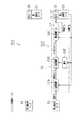
図14は、第1システムSY1〜第3システムSY3の正常時における第1ECU21〜第3ECU23の制御ブロックの構成を示している。
【0194】
第1ECU21は、始動時制御モード及び正常時制御モードでの構成は、第2実施形態の構成と同様であるため、同一構成には同一符号を付して、その説明を省略する。なお、トルク指令ΔP10は速度制御による演算結果に基づいて生成された第1トルク指令に相当する。
【0195】
そして、トルク分配部21Bの分配の仕方が第2実施形態と異なっている。
すなわち、トルク分配部21Bは、供給されたトルク指令ΔP10をトルク指令ΔP11、トルク指令ΔP12、トルク指令ΔP14に分配し、それぞれ第1システムSY1の電流制御部21C、第2システムSY2の電流制御部22C、第3システムSY3の電流制御部23Cに供給する(図14参照)。
【0196】
本実施形態においては、第1実施形態と同様にトルク分配部21Bは、操舵制御装置に含まれる全システムが正常時において、車両のエンジン始動時での分配比をエンジンの始動時以外のときの分配比と異なるようにし、その分配比を可変する。
【0197】
すなわち、車両のエンジン始動時(始動時制御モード)での分配比は100/3:0:0(=ΔP11:ΔP12:ΔP14)とされ、車両のエンジン始動時以外(正常時制御モード)の分配比は100/3:100/3:100/3(=ΔP11:ΔP12:ΔP14)とされている。
【0198】
第1ECU21による第1モータ36の舵取制御は、転舵角が操舵角と対応するように制御する位置制御と、速度指令C1にモータ速度が対応するように制御する速度制御と、そのためにモータシャフト39に必要な推力、すなわち、出力トルクを得るためのトルク制御とが含まれる。
【0199】
そして、電流制御部21Cでは、電流フィードバック制御が行われ、指令値(トルク指令ΔP11)とフィードバック値(第1モータ36の電流値iq及び電流値id)の偏差が0になるように制御する。
【0200】
前記電流制御は、トルク制御に相当する。
(1−2) 第1フェィル時制御モード
第1システムSY1が正常であり、第2及び第3システムSY3のうち、いずれかのシステムが異常時の場合は、第1ECU21は第1フェィル時制御モードとなる。
【0201】
第1フェィル時制御モードでは、第1ECU21のトルク分配部21Bは、異常なシステムを除いた正常なシステムのために、トルク指令ΔP10を再分配する。
【0202】
図15は、第3システムSY3が異常であり、第2システムSY2が正常の例を示している。
なお、第2システムSY2が異常で、かつ、第3システムが正常の場合は、以下、図15の例で説明する第2システムSY2に関する記述を第3システムSY3に関するものと読み替えれば良いため、第2システムSY2が異常で、かつ、第3システムが正常の場合の説明を省略する。
【0203】
図15の例では、第3システムSY3の第3ECU23は第3モータ43の制御を停止する。
又、第1システムSY1のトルク分配部21Bは、トルク指令ΔP10を第1システムSY1及び第2システムSY2のトルク指令のために、再分配する。
【0204】
すなわち、トルク分配部21Bは供給されたトルク指令ΔP10をトルク指令ΔP11a、トルク指令ΔP12aに分配し、それぞれ第1システムSY1の電流制御部21C、第2システムSY2の電流制御部22Cに供給する(図15参照)。この時の分配比は50:50(=ΔP11a:ΔP12a)
なお、第1フェィル時制御モードでは、正常である各システムの電流制御部のPI制御部64,PI制御部65は、全システムが正常時の場合の正常時制御モードのときと電流ループゲインが異なるようにされている。なお、電流ループゲインは、PI制御部64,PI制御部65における積分ゲイン及び比例ゲインのことである。フェィル時制御モードでのこれらのゲインは、正常時制御モードのこれらのゲインよりも大きく設定されている。
【0205】
第1フェィル時制御モードでの電流ループゲインが正常時制御モードの電流ループゲインよりも大きくされていることにより、ステアリングホイール10の操作に対する応答性の低下が生ぜず、又、ステアリングホイール10の操作への追従性が低下しないようにされている。
【0206】
又、トルク指令ΔP10は下記のように設定されている。
図15の例では、車両走行中は路面反力が小さいため、車両走行中において第1及び第2モータ37でモータシャフト39を駆動した場合に得られる推力(出力トルク)による転舵範囲が、操舵制御装置に含まれる全システムの正常時に得られる転舵範囲と同じとなるように、トルク指令ΔP10は設定されている。
【0207】
又、車両が走行停止した状態で据え切り操舵を行った場合、路面反力が大きいため、第1モータ36及び第2モータ37にて得られたる推力(出力トルク)により、操舵制御装置に含まれる全システムの正常時よりも転舵範囲が狭まった転舵範囲が得られるように、トルク指令ΔP10は設定されている。
【0208】
本実施形態では、トルク指令ΔP10は正常時制御モードでのトルク指令ΔP11とトルク指令ΔP12の合計値と同じ値とされている(図14参照)。
2.第2ECU22及び第3ECU23
次に、第2ECU22及び第3ECU23について説明する。
【0209】
(2−1)第1ECU21の始動時制御モード、及び正常時制御モード
第1ECU21の正常時制御モードでは、第2ECU22及び第3ECU23は、図14に示すように、電流制御部22C、電流制御部23Cを備える。そして、電流制御部22C及び電流制御部23Cは分配されたトルク指令ΔP12、トルク指令ΔP14を入力する。
【0210】
正常時制御モードでの電流制御部22C、及び電流制御部23Cは、電流制御部21Cと同様の構成のため、図6で示す電流制御部21Cの構成と同一構成又は相当する構成については、同一符号を付してその説明を省略する。
【0211】
そして、電流制御部22Cは、電流フィードバック制御を行ない、指令値(トルク指令ΔP12)とフィードバック値(第2モータ37の電流値iq及び電流値id)の偏差が0になるように制御する。
【0212】
又、電流制御部23Cは、電流フィードバック制御を行ない、指令値(トルク指令ΔP14)とフィードバック値(第3モータ43の電流値iq及び電流値id)の偏差が0になるように制御する。
【0213】
前記電流制御は、トルク制御に相当する。
(2−2) 第2フェィル時制御モード
次に、第1システムSY1がフェィル時の場合について説明する。
【0214】
第1システムSY1が異常時の際、第2システムSY2が正常の場合は、第2システムSY2の第2ECU22が、第3システムSY3の第3ECU23よりも上位のコントローラとして機能する。
【0215】
又、第1システムSY1及び第2システムSY2が異常で、第3システムSY3が正常の場合は、第3システムSY3の第3ECU23が操舵制御装置のコントローラとして機能する。
【0216】
第2フェィル時制御モードは、第1システムSY1のみのフェィル時の場合と、第1システムSY1及び他の1つのシステムが同時に異常となった場合に対応させたものである。
【0217】
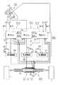
(2−2−1) 第1システムSY1のみのフェィル時の場合
第1システムSY1のみのフェィル時では、図16に示すように第1システムSY1の第1ECU21は、第1モータ36の制御を停止する。
【0218】
そして、このフェィル時に、第2システムSY2及び第3システムSY3が正常時である場合について、「第2ECU22」と「第3ECU23」のそれぞれの機能を説明する。
【0219】
第2ECU22は、第2フェィル時制御モードでは、図16に示すように、位置制御部22A、トルク分配部22B、電流制御部22C、速度制御部22D、及び微分処理部22Eを備える。
【0220】
第2フェィル時制御モードにおける、第2ECU22による第2モータ37の舵取制御は、転舵角が操舵角と対応するように制御する位置制御と、速度指令C2にモータ速度が対応するように制御する速度制御と、そのためにモータシャフト39に必要な推力である出力トルクを得るためのトルク制御とを含む。
【0221】
第2フェィル時制御モードでは、第2ECU22は、第2操舵角センサ15が検出した操舵角に対応する転舵角(操舵輪の転舵角)が得られるように、かつ、そのためにモータシャフト39に必要な推力が得られるように第2駆動回路57を介して第2モータ37を舵取制御を実行する。
【0222】
詳説すると、位置制御部22Aは、第2操舵角センサ15が検出した操舵角を位置指令として入力するととともに第2回転角センサ53からの検出信号を入力し、同信号に基づいてモータシャフト39のステータに対する回転角を算出する。
【0223】
第2回転角センサ53からの検出信号は第2モータ37(電動モータ)の位置情報に相当する。
位置制御部22Aは、算出した電動モータ(第2モータ37)の回転角と、位置指令としての操舵角に基づく操舵位置との偏差を演算し、その偏差に対して、位置制御に必要な所定のゲインを乗算し、その乗算値を速度指令C2として速度制御部22Dに供給する。
【0224】
微分処理部22Eは、第2回転角センサ53からの検出信号を入力して同信号に基づいてモータ速度を算出し、速度制御部22Dにその算出値を入力する。
速度制御部22Dは、速度指令C2と、モータ速度との偏差を演算し、その偏差に対して、速度制御に必要な所定のゲインを乗算し、その乗算値をトルク指令ΔP13としてトルク分配部22Bに供給する。
【0225】
すなわち、速度制御部22Dでは、速度制御が行われ、指令値(速度指令C2)及びフィードバック値(第2モータ37のモータ速度)の偏差が0になるように制御する。
【0226】
トルク指令ΔP13は速度制御による演算結果に基づいて生成された第2トルク指令に相当する。
トルク分配部22Bは、供給されたトルク指令ΔP13を正常なシステムの数に応じた分配比で分配し、分配したトルク指令ΔP15とトルク指令ΔP16とをそれぞれ第2システムSY2の電流制御部22Cと第3システムSY3の電流制御部23Cに供給する。
【0227】
すなわち、この例では、操舵制御装置に含まれる第1システムSY1が異常であり、第2システムSY2及び第3システムSY3が正常の場合である。従って、前記正常なシステムへの分配比は50:50(=ΔP15:ΔP16)とされている。
【0228】
なお、本実施形態では、各システムの電流制御部のPI制御部64,PI制御部65では、全システムが正常時の場合の正常時制御モードのときと電流ループゲインが異なるようにされている。なお、電流ループゲインは、PI制御部64,PI制御部65における積分ゲイン及び比例ゲインのことである。フェィル時制御モードでのこれらのゲインは、正常時制御モードのこれらのゲインよりも大きく設定されている。
【0229】
第2フェィル時制御モードでの電流ループゲインが正常時制御モードの電流ループゲインよりも大きくされていることにより、ステアリングホイール10の操作に対する応答性の低下が生ぜず、又、ステアリングホイール10の操作への追従性が低下しないようにされている。
【0230】
又、トルク指令ΔP13は下記のように設定されている。
すなわち、車両走行中は路面反力が小さいため、第2及び第3モータ43でモータシャフト39を駆動した場合に得られる推力(出力トルク)による転舵範囲が、操舵制御装置に含まれる全システムの正常時の転舵範囲と同じになるように、トルク指令ΔP13が設定されている。
【0231】
又、トルク指令ΔP13は、車両が走行停止した状態で据え切り操舵を行った場合、路面反力が大きいため、第2モータ37及び第3モータ43にて得られたる推力(出力トルク)では、操舵制御装置に含まれる全システムの正常時よりも転舵範囲が狭まった転舵範囲が得られるように設定されている。
【0232】
本実施形態では、トルク指令ΔP13は正常時制御モードでのトルク指令ΔP12とトルク指令ΔP14の合計値と同じ値とされている。
第2フェィル時制御モードでの、電流制御部22Cは、正常時制御モードでの電流制御部21Cと同様の構成であるため、図6で示す電流制御部21Cの構成と同一構成又は相当する構成については、同一符号を付してその説明を省略する。
【0233】
そして、電流制御部22Cの各部は、トルク指令ΔP15、第2回転角センサ53の検出信号、及び電流センサ71,72からの励磁電流iu,ivに係る電流検出値信号を処理する。この処理により、第2ECU22からは、パルス信号(PWM制御信号)を第2駆動回路57へ出力する。第2駆動回路57は、それらのパルス信号(PWM制御信号)に基づいて第2モータ37の各相へ駆動電圧を印加する。
【0234】
以上のようにして、第2フェィル時制御モードにおいて、電流制御部22Cでは、電流制御が行われ、指令値(トルク指令ΔP15)及びフィードバック値(第2モータ37の電流値iq及び電流値id)の偏差が0になるように制御する。
【0235】
前記電流制御は、トルク制御に相当する。
一方、第1システムSY1のみのフェィル時の場合、第3ECU23は、図16に示すように、電流制御部23Cを備える。
【0236】
又、電流制御部23Cは、電流フィードバック制御を行ない、指令値(トルク指令ΔP16)とフィードバック値(第3モータ43の電流値iq及び電流値id)の偏差が0になるように制御する。
【0237】
前記電流制御は、トルク制御に相当する。
(2−2−2) 第1システムSY1及び他のシステムのフェィル時の場合
第1システムSY1及び他の1つのシステムが同時にフェィルしたときは、第1システムSY1の第1ECU21が、第1モータ36の制御を停止し、他の1つのシステムのECUがそのシステムのモータの制御を停止する第2フェィル時制御モードとなる。
【0238】
図17では、第1システムSY1及び第3システムSY3のフェィル時の場合を示している。この場合、第2システムSY2のみが正常である。
なお、第2システムSY2が異常で、かつ、第3システムが正常の場合は、以下、図17の例で説明する第2システムSY2に関する記述を第3システムSY3に関するものと読み替えれば良いため、第2システムSY2が異常で、かつ、第3システムが正常の場合の説明を省略する。
【0239】
この場合、第2ECU22は、図17に示すように、位置制御部22A、トルク分配部22B、電流制御部22C、速度制御部22D、及び微分処理部22Eを備える。
【0240】
これらの各部の構成は、図16に示す構成と同じとされているが、トルク分配部22Bにおける分配比が異なっている。すなわち、この例ではトルク分配部22Bは分配比は100:0(=ΔP15:ΔP16)とされている。従って、トルク分配部22Bから電流制御部22Cに出力されるトルク指令ΔP15はΔP13と同じである。又、図示はしていないが、トルク分配部22Bからはトルク指令ΔP16が第3ECU23に出力されるものの、そのトルク指令ΔP16は0である。
【0241】
(第3実施形態の作用)
第3実施形態においては第1ECU21は図13に示す舵取制御の制御プログラムのフローチャートを所定周期毎に実行する。
【0242】
さて、上記のように構成された、操舵制御装置の作用を説明する。
S100では、前記S10と同様に図示しないエンジンが始動されたか、或いは始動後か否かを判定する。エンジンが始動された場合には、S200において、第1ECU21は始動時制御モードに入り、このステップを一旦終了する。
【0243】
従って、イグニッションスイッチのオン信号の入力から所定時間内は第1システムSY1の第1ECU21は始動時制御モードとなる。
又、第2システムSY2の第2ECU22、及び第3システムSY3の第3ECU23は、第1ECU21からのトルク指令ΔP12、トルク指令ΔP14の入力により、始動時制御モードとなる。
【0244】
イグニッションスイッチのオン信号の入力から所定時間を経過した場合には、S100の判定は「NO」となり、S300において、全システムが正常状態か否かを、他のシステムから入力したエラー情報に基づいて判定する。
【0245】
S300において、全システムが正常であると判定すると、S400において、正常時制御モードの処理を実行し、一旦この処理を終了する。S400では、各システムにおいて、第1モータ36、第2モータ37及び第3モータ43は、分配されたトルク指令ΔP11、トルク指令ΔP12及びトルク指令ΔP14に基づいて同時に駆動される。
【0246】
S300において、全システムは正常ではないと判定すると、S500において、他のシステムから入力したエラー情報に基づいて、どのシステムが異常か否かを判定する。第1システムSY1が異常である場合には、S700に移行し、第1システムSY1が正常であれば、S600に移行する。
【0247】
S600では、第1フェィル時処理を行う。すなわち、第1ECU21は、第1フェィル時制御モードとなる。このモードでは、第1ECU21のトルク分配部21Bは、異常なシステムを除いた正常なシステムのために、トルク指令ΔP10を再分配し、この処理を一旦終了する。
【0248】
なお、このとき、異常となったシステムのECUは制御対象のモータの制御を停止する。
S700では、第1ECU21は第2フェィル時処理を行う。
【0249】
すなわち、第1ECU21は、図16に示すように第1モータ36の制御を停止する。
このとき、第1システムSY1のみのフェィル(故障)時の場合、第2システムSY2の第2ECU22が、第3システムSY3の第3ECU23よりも上位のコントローラとして機能する。すなわち、前述した「(2−2−1) 第1システムSY1のみのフェィル時の場合」に記述した処理を行い、一旦、この処理を終了する。
【0250】
又、第1システムSY1及び他の1つのシステムがフェィル時の場合、正常であるシステムのECUが、「(2−2−2) 第1システムSY1及び他のシステムのフェィル時の場合」に記述した処理を行い、この処理を一旦終了する。
【0251】
従って、第3実施形態によれば、以下のような特徴がある。
(1) 第3実施形態の操舵制御装置では、舵取機構200の前輪T(操舵輪)上に同軸形状に一体配置された3個の概同一性能のモータと、各モータを制御する制御手段を含む複数のシステムを備えた。そして、各システムのモータを同時に制御して共通の舵取機構200を駆動するようにした。
【0252】
又、第1システムSY1の第1ECU21は、ステアリングホイール10(操舵ハンドル)の操舵位置と自身のシステムのモータの位置情報に基づいて舵取機構200を駆動するために必要となるトルク指令ΔP10(第1トルク指令)を生成し、トルク指令ΔP10をシステムの数に応じて分配した。そして、第1ECU21は分配後の自身のシステム用のトルク指令ΔP11に基づいてモータに対してトルク制御を行うようにした。さらに、他のシステムの第2ECU22及び第3ECU23(制御手段)は、当該システムに分配されたトルク指令ΔP12及びトルク指令ΔP14に基づいて当該システムのモータに対してトルク制御を行うようにした。
【0253】
このように、1つのシステムが、上位制御ループ(位置制御や速度制御)を統括して、操舵制御装置全体に必要なトルクを算出し、それを他のシステムにトルク指令として分配して、各システムは各自でトルク制御(下位制御ループ)を行うようにした。
【0254】
この結果、3つのシステムの各モータを同時駆動する際、位置制御を第1システムSY1でのみ行っているため、両モータのトルク干渉の問題はなく、トルク干渉に起因したトルクの低下を生ずることがない。そして、トルクの低下が生ずることがないため、ステアリングホイール10の操作に対する応答性の低下が生ぜず、ステアリングホイール10の操作への追従性が低下することもない。
【0255】
又、トルク干渉がないため、異音、振動、発熱の発生を抑えることができる効果を奏する。
(2) 第3実施形態では、第1ECU21、第2ECU22、及び第3ECU23はそれぞれ自身のシステム以外の他のシステムの故障検出を行う故障検出手段とした。そして、トルク指令ΔP10を生成していた第1システムSY1を含む1つ以上のシステムが故障した場合、他の正常なシステムの1つのECU(制御手段)は、ステアリングホイール10の操舵位置と自身のシステムのモータの位置情報に基づいてトルク指令ΔP13(第2トルク指令)を生成した。
【0256】
そして、トルク指令ΔP13(第2トルク指令)を残りの正常なシステムの数に応じて分配し、分配後の自身のシステム用のトルク指令ΔP15に基づいてモータに対してトルク制御を行うようにした。
【0257】
又、このとき、他の正常なシステムのECU(制御手段)は、当該システムに分配されたトルク指令ΔP16に基づいて当該システムのモータに対してトルク制御を行うようにした。
【0258】
この結果、少なくとも第1システムSY1が故障した場合でも、第2システムSY2等の他のシステムが、当該システムのモータを駆動制御することができ、バックアップすることができる。
【0259】
このように、1つ以上のシステムが故障した場合、故障したシステムの中に上位制御ループ(位置制御や速度制御)を統括していたシステムが含まれている場合、他の正常なシステムの1つが上位制御ループを新たに統括し、改めて算出された全体必要トルクを正常なシステムの数に応じて分配するようにした。
【0260】
そして、複数の概同一性能のモータが同軸上に一体に配置されていることにより、モータ性能差による制約がないため、故障時のトルクの分配が容易となり、性能低下も防ぐことができる。
【0261】
(3) 第3実施形態は、第1ECU21、第2ECU22、及び第3ECU23はそれぞれ自身のシステム以外の他のシステムの故障検出を行う故障検出手段とした。
【0262】
そして、トルク指令ΔP10を生成していた第1システムSY1を除く1つ以上のシステムが故障した場合、第1システムSY1の第1ECU21(制御手段)は、トルク指令ΔP10(第1トルク指令)を残りの正常なシステムの数に応じて再分配した。そして、第1ECU21は分配後の自身のシステム用のトルク指令ΔP11aに基づいて当該電動モータに対してトルク制御を行うようにした。
【0263】
又、他の正常なシステム(図15の例では第2システムSY2)のECU(制御手段)は、当該システムに分配されたトルク指令ΔP12aに基づいて当該システムのモータに対してトルク制御を行うようにした。
【0264】
この結果、第1システムSY1以外のシステムが故障した場合には、トルク指令ΔP10(第1トルク指令)を残りの正常なシステムの数に応じて再分配することにより、第1システムSY1等の他のシステムが、当該システムのモータを駆動制御することができ、バックアップすることができる。
【0265】
このように、故障システムの中に上位制御ループ(位置制御や速度制御)を統括していたシステムが含まれていない場合、上位制御ループを統括するシステムはそのままで、全体必要トルクを正常なシステムの数に応じて再分配するようにした。
【0266】
そして、複数の概同一性能のモータが同軸上に一体に配置されていることにより、モータ性能差による制約がないため、故障時のトルクの再分配が容易となり、性能低下も防ぐことができる。
【0267】
(4) 第3実施形態では、トルク制御は、モータ(電動モータ)の電流をフィードバック制御する電流制御を含むようにした。そして、各システムの第1ECU21〜第3ECU23(制御手段)は、全システム正常時と1つ以上のシステムの故障時とでは、電流制御の電流ループゲインを可変にした。
【0268】
この結果、1つ以上のシステムが故障した場合には、ステアリングホイール10の操作に対する応答性の低下を抑制できる効果がある。
なお、本発明の実施形態は、上記実施形態に限定されるものではなく、次のように変更してもよい。
【0269】
(1) 前記実施形態では、システムは、2又は3つのシステムとしたが、すなわち、4つ以上のシステムを設けてもよい。
この場合、1つのシステムは、位置制御、電流制御の上位制御ループを統括し、他のシステムは、電流制御の下位制御ループを行うようにするものとする。
【0270】
そして、1つのシステムが異常になった際、残りのシステムのうち、1つのシステムでは、位置制御、電流制御を行い、他のシステムは、電流制御を行うようにするものとする。
【0271】
或いは、4つ以上のシステムの場合、全システムが正常の場合には、1つのシステムは、位置制御、速度制御、電流制御の上位制御ループを統括し、他のシステムは、電流制御の下位制御ループを行うようにするものとする。
【0272】
そして、1つのシステムが異常になった際、残りのシステムのうち、1つのシステムでは、位置制御、速度制御、電流制御を行い、他のシステムは、電流制御を行うようにするものとする。
【0273】
従って、正常時には、複数の全システムに係るモータの合成出力で、舵取機構200を駆動し、1つのシステムが異常の場合には、残りのシステムのモータの合成出力トルクにて舵取機構200を駆動することになる。
【0274】
(2) 第1乃至第3実施形態では、第1回転角センサ52等の回転角センサをロータリーエンコーダにて構成したが、第1モータ36等のモータと所定の電気角を有して同モータの回転変位を検出するものであれば、その他の回転変位検出手段、例えばレゾルバ等に具体化してもよい。
【0275】
(3) 前記実施形態では、ステアバイワイヤ式の操舵制御装置に具体化したが、電動パワーステアリング制御装置に具体化してもよい。例えば、シャフト35を、ラックシャフトとして構成し、同ラックシャフトに対してステアリングホイールとラックアンドピニオンで連結する構成とする。
【0276】
【発明の効果】
以上、詳述したように、請求項1乃至請求項4に記載の発明によれば、複数のシステムの各電動モータを同時駆動する際、電動モータのトルク干渉の問題を解消して、トルクの低下を生ずることがなく、異音、振動、発熱の発生を抑えることができる。
【0277】
請求項2及び請求項3に記載の発明によれば、複数の概同一性能のモータが同一軸上に一体配置されているため、故障時のトルク指令の分配が容易となり、故障時の舵取機構の性能低下を防止することができる。
【0278】
請求項4に記載の発明によれば、全システム正常時には異音、振動等の観点により低く抑えていた各電流ループゲインを故障時には所定の値まで上げることにより、故障時の舵取機構の性能低下を防ぐことができる効果を奏する。
【図面の簡単な説明】
【図1】 第1実施形態の操舵制御装置の全体を示す概略図。
【図2】 同じく操舵制御装置の舵取機構200の要部拡大図。
【図3】 同じくモータハウジング32内の構成を示す断面図。
【図4】 同じく第1駆動回路55及びその周辺回路の電気回路図。
【図5】 正常時制御モードにおける各システムの制御ブロックの概念図。
【図6】 電流制御部21Cの制御ブロック図。
【図7】 フェィル時制御モードにおける各システムの制御ブロックの概念図。
【図8】 第1ECU21が実行する制御フローチャート。
【図9】 従来技術の方法で行う場合の参考例における各システムの制御ブロックの概念図。
【図10】 第2実施形態の正常時制御モードにおける各システムの制御ブロックの概念図。
【図11】 同じくフェィル時制御モードにおける各システムの制御ブロックの概念図。
【図12】 第3実施形態の操舵制御装置の全体を示す概略図。
【図13】 第3実施形態における第1ECU21が実行するフローチャート。
【図14】 第3実施形態の正常時制御モードにおける各システムの制御ブロックの概念図。
【図15】 同じく第1フェィル制御モード時における各システムの制御ブロックの概念図。
【図16】 同じく第2フェィル制御モード時における各システムの制御ブロックの概念図。
【図17】 同じく第2フェィル制御モード時における各システムの制御ブロックの概念図。
【図18】 従来技術の方法で行う場合の参考例における各システムの制御ブロックの概念図。
【符号の説明】
10…ステアリングホイール(操舵ハンドル)
21…第1ECU(制御手段)
22…第2ECU(制御手段)
23…第3ECU23(制御手段)
36…第1モータ(電動モータ)
37…第2モータ(電動モータ)
43…第3モータ(電動モータ)
52…第1回転角センサ
53…第2回転角センサ
54…第3回転角センサ
55…第1駆動回路
57…第2駆動回路
58…第3駆動回路
200…舵取機構
T…前輪(操舵輪)
SY1…第1システム
SY2…第2システム
SY3…第3システム[0001]
BACKGROUND OF THE INVENTION
The present invention relates to a steering control device for a vehicle used in a steer-by-wire type steering control device or an electric power steering control device.
[0002]
[Prior art]
2. Description of the Related Art Conventionally, as a vehicle steering control device for controlling a steering wheel of a vehicle, a steer-by-wire type steering control device in which a steering wheel and a steering gear box connected to a front wheel (steering wheel) are mechanically separated is known. .
[0003]
The steering control device detects the steering angle of the steering wheel without directly connecting the steering wheel and the steering gear box, and drives the steering gear box via an electric motor in accordance with the detected steering angle. ing.
[0004]
In this type of steering control device, some kind of backup system is provided so that the steering operation can be reliably continued when the device fails.
As this backup system, for example, a configuration including two redundant systems has been proposed (see Patent Document 1).
[0005]
One system is a main system, and includes one electric motor that drives a shaft coupled to a steered wheel, one drive circuit that drives the motor, and one drive that controls the electric motor via the drive circuit. A control circuit and various sensors necessary for control are provided. Another system is a sub-system and has the same configuration as the main system.
[0006]
In an apparatus equipped with two systems, when each system is normal, the respective motors of both systems are driven and controlled at the same time so that they do not interfere with each other, and the electric motor on the main system side responds to the steering angle of the steering wheel. Drive the shaft.
[0007]
When there is any failure on the main system side, the electric motor is stopped and the shaft is driven by the remaining electric motor on the sub system side.
[0008]
[0009]
[Patent Document 1]
Japanese Patent Laying-Open No. 2002-37112 (FIG. 1, paragraphs “0015” to “0028”)
[Patent Document 2]
Japanese Patent Laid-Open No. 10-218000
[0010]
[Problems to be solved by the invention]
By the way, in the control method of the electric motor, the position of the electric motor is controlled based on the detection value of the steering angle sensor that detects the steering angle of the steering wheel. At this time, when attempting to drive a plurality of electric motors simultaneously, interference of motor torque may be a problem.
[0011]
For example, when position feedback control is performed based on the rotation angle of an electric motor by a rotation angle sensor provided in each electric motor, each electric motor differs depending on an assembly error of the electric motor or an assembly error of the rotation angle sensor. It will be controlled to the position. For this reason, there is a problem that the direction of the generated torque does not match, the torque is reduced, noise or vibration is generated, and the electric motor generates heat.
[0012]
In the technique of
[0013]
When the interference of the motor torque occurs, it is conceivable to stop one of the systems as in the case where the mutual interference due to the control error occurs.
However, in this control method, the operation of one system is stopped, and thus the shaft connected to the steered wheels is driven only by the remaining electric motor even though both systems themselves are normal. This is an undesirable method when the system is normal.
[0014]
In the technique of
[0015]
Accordingly, since the motor performance (motor characteristics) is not uniform, torque distribution can be performed only at a predetermined ratio. In addition, depending on which motor has failed, there will be a difference in performance after the failure.
[0016]
An object of the present invention is to solve the problem of electric motor torque interference when simultaneously driving each electric motor of a plurality of systems, and to prevent generation of noise, vibration, and heat generation without causing torque reduction. It is an object of the present invention to provide a vehicle steering control device.
[0017]
Another object of the present invention is to provide a vehicle steering control device that is easy to distribute torque in the event of a system failure and can prevent performance degradation because there is no restriction due to performance differences among a plurality of motors. is there.
[0018]
[Means for Solving the Problems]
In order to solve the above-mentioned problems, the invention according to
[0019]
According to a second aspect of the present invention, in the first aspect, in the case where one or more systems including a system that has generated the first torque command has failed, the apparatus includes a failure detection unit that detects a failure of each system. One control means of another normal system generates a second torque command necessary for driving the steering mechanism based on the steering position of the operation handle and the position information of the electric motor of its own system. The second torque command is distributed according to the number of remaining normal systems, the torque control is performed on the electric motor based on the torque command for its own system after the distribution, and other normal system The control means performs torque control on the electric motor of the system based on a torque command distributed to the system.
[0020]
In the present specification, “distributing the second torque command according to the number of remaining normal systems” means that in the case of a steering control device having two systems, the system that generates the first torque command This is intended to include a case where the generated second torque command is used only for its own system in the remaining normal systems when a failure occurs.
[0021]
The invention of
[0022]
In this specification, “redistributing the first torque command according to the number of remaining normal systems” means that only the system that generates the first torque command is normal and all other systems have failed. This includes the case where the generated first torque command is used only for its own system.
[0023]
According to a fourth aspect of the present invention, in the second or third aspect, the torque control includes a current control that feedback-controls an electric motor current, and each system has one or more control means when the entire system is normal. When a system failure occurs, the current loop gain of the current control is made variable.
[0024]
DETAILED DESCRIPTION OF THE INVENTION
Hereinafter, an embodiment in which the present invention is embodied in a steer-by-wire steering control device (hereinafter simply referred to as a steering control device) mounted on a vehicle will be described in detail with reference to FIGS.
[0025]
FIG. 1 shows a conceptual diagram of the steering control device of the present embodiment.
The steering control device includes an
[0026]
(Operation mechanism 100)
The
[0027]
The rotation shaft 11 is provided with a first
[0028]
The first
[0029]
(Steering mechanism 200)
Next, the
[0030]
The hollow cylindrical
[0031]
A
[0032]
Next, the configuration inside the
A pair of motors (electric motors) are provided in the
[0033]
The
[0034]
The
[0035]
The first motor winding 41 and the second motor winding 42 are covered with an insulating resin by molding.
In the present embodiment, the first motor winding 41 and the second motor winding 42 are wound around the
[0036]
For example, each of the
[0037]
And the winding wound around each
[0038]
The
[0039]
The
The
[0040]
The other end side of the
[0041]
As described above, the
[0042]
Further, a
[0043]
A ball screw nut 49 is coaxially fitted in the
[0044]
On the outer peripheral surface of the
[0045]
Then, the output torque of the forward / reverse rotation of the
Further, a first
[0046]
Both rotation angle sensors respectively input a two-phase pulse train signal having a phase difference of π / 2 according to the rotation of the
[0047]
Detection signals from the first
The
[0048]
(Control unit 300)
Next, the
The
[0049]
Each of the
1. About 1ECU21
The
[0050]
As the control mode of the
(
In the start time control mode and the normal time control mode, the
[0051]
More specifically, the
[0052]
The
[0053]
The torque command ΔP corresponds to the first torque command generated based on the calculation result by the position control.
In the
[0054]
The
[0055]
The
[0056]
In the present embodiment, the distribution ratio when the vehicle engine is started (startup control mode) is 50: 0 (= ΔP1: ΔP2), and the distribution ratio is 50 when the vehicle engine is not started (normal control mode). : 50 (= ΔP1: ΔP2).
[0057]
Steering control of the
[0058]
FIG. 6 is a control block diagram of the
The
[0059]
In the normal time control mode, the
[0060]
That is, the
The d /
[0061]
These excitation currents iu, iv, iw correspond to the actual current of the
The d /
[0062]
In the d / q conversion, orthogonal coordinates are set with the same direction as the magnetic flux of the rotor of the electric motor as the d-axis and the direction orthogonal to the d-axis as the q-axis. This is a known technique for converting alternating current into direct current by mapping a vector of flowing alternating current.
[0063]
Further, the
[0064]
On the other hand, the
[0065]
The
[0066]
The d /
[0067]
As described above, in the
[0068]
The current control corresponds to torque control.
(During first system SY1 failure)
When the first system SY1 fails, the
[0069]
2. About 2ECU22
The
[0070]
The
[0071]
(Start-up control mode and normal-time control mode of the second ECU 22)
In the start time control mode and the normal time control mode, as shown in FIG. 5, the
[0072]
In the
[0073]
Since the
[0074]
Each of these units, like each unit of the
[0075]
As described above, the
[0076]
The current control corresponds to torque control.
In the starting control mode, the
[0077]
(Fail control mode of the second ECU 22)
The steering control of the
[0078]
That is, in the fail control mode, the
[0079]
More specifically, the
[0080]
The detection signal from the second
The
[0081]
The torque command ΔP3 corresponds to the second torque command.
The
[0082]
The torque command ΔP3 is set as follows.
That is, since the road surface reaction force is small while the vehicle is traveling, the steering control device includes a turning range based on thrust (output torque) obtained when the
[0083]
In addition, when the vehicle stops traveling, when the stationary steering is performed, the road surface reaction force is large. Therefore, with only the thrust of the
[0084]
In the present embodiment, the torque command ΔP3 has the same value as the torque command ΔP2 in the normal time control mode.
Since the
[0085]
In the present embodiment, the
[0086]
Since the current loop gain in the fail-time control mode is larger than the current loop gain in the normal-time control mode, the response to the operation of the
[0087]
Each unit of the
[0088]
As described above, in the fail control mode, the
[0089]
The current control corresponds to torque control.
(First drive
As described above, the steering control device according to the present embodiment has a redundant configuration including two systems.
[0090]
One system, that is, the first system SY1, includes the
[0091]
Here, the configuration of the
Note that the
[0092]
The
[0093]
[0094]
A PWM control signal is input from the
The
[0095]
1 and 4, a
[0096]
Further, a phase
[0097]
Also, the
[0098]
When one system determines that there is an abnormality with respect to the other system, the same system turns off the
[0099]
As described above, the
(Operation of the first embodiment)
Now, the operation of the steering control device configured as described above will be described.
[0100]
FIG. 8 is a flowchart of a control program for steering control executed by the
In S10, it is determined whether an engine (not shown) has been started or has been started. This determination is made based on whether or not an ON signal input to an ignition switch (not shown) has been input to the
[0101]
Accordingly, the
[0102]
If a predetermined time has elapsed since the ignition switch ON signal was input, the determination in S10 is “NO”, and in S30, it is determined whether or not the first system SY1 is in an abnormal state.
[0103]
This determination is made based on error information α21 (abnormality determination signal) from the
The
[0104]
The abnormality of the first system SY1 includes abnormality of each component constituting the first system SY1, such as abnormality of sensors (first steering angle sensor 14), abnormality of the
[0105]
In S30, when it is determined that the first system SY1 is normal based on the error information α21 (abnormality determination signal) from the
[0106]
On the other hand, the second system SY2 enters the normal control mode when the torque command ΔP2 is input from the
[0107]
If it is determined in S30 that the first system SY1 is abnormal based on the error information α21 from the
[0108]
As a result, the supply of the excitation current to the first motor winding 41 of the
On the other hand, when the
[0109]
At this time, since the
[0110]
However, while the vehicle is traveling, the front wheel T (steering wheel) can be sufficiently steered even with a thrust (output torque) that is half of the thrust (output torque) of the
[0111]
Further, in the first system SY1, since the phase release relays 210 and 220 are turned off, the
[0112]
According to this embodiment, the following features can be obtained.
(1) In the steering control device of the present embodiment, two first and
[0113]
Further, the
[0114]
In this way, one system controls the upper control loop (position control), calculates the torque required for the entire steering control device, distributes it to other systems as a torque command, and each system has its own system. Torque control (lower control loop) was performed.
[0115]
As a result, when the motors of the two systems are driven simultaneously, the position control is performed only by the first system SY1, so there is no problem of torque interference between the two motors, and the torque is reduced due to the torque interference. There is no. And since the torque does not decrease, the response to the operation of the
[0116]
Further, since there is no torque interference, there is an effect that generation of abnormal noise, vibration, and heat generation can be suppressed.
FIG. 9 is a reference example of a conventional configuration.
[0117]
In this case, the first system SY1 includes a
[0118]
In this case, in each system, position feedback control is performed based on the rotation angle of each motor by the first
[0119]
This is not the case in the first embodiment.
(2) In the first embodiment, each of the
[0120]
Then, the torque command ΔP3 (second torque command) is distributed according to the number of normal systems (one in the first embodiment), and is distributed to the motor based on the torque command ΔP3 for its own system after distribution. Torque control was performed.
[0121]
As a result, even when the first system SY1 breaks down, the second system SY2 can drive and control the
In this way, when one system fails, if the system that has supervised the upper control loop (position control) is included in the failed system, one of the other normal systems has the upper control loop. Newly integrated and newly calculated total required torque is distributed according to the number of normal systems.
[0122]
Since a plurality of motors having substantially the same performance are integrally arranged on the same axis, there is no restriction due to a difference in motor performance, so torque distribution at the time of failure can be facilitated and performance degradation can be prevented.
[0123]
(3) In the first embodiment, when the first system SY1 fails, the
[0124]
As a result, when the first system SY1 breaks down, it is possible to suppress a decrease in responsiveness to the operation of the
(Second Embodiment)
Next, a second embodiment will be described with reference to FIGS.
[0125]
Since the hardware configuration of the steering control device of the present embodiment is the same as that of the first embodiment, the same or corresponding components as those of the first embodiment are denoted by the same reference numerals, the description thereof is omitted, and is different. However, the explanation will be focused on.
[0126]
In the first embodiment, position feedback control and current feedback control are executed. However, in this embodiment, speed feedback control is further performed in addition to position feedback and current feedback control.
[0127]
(
The one-dot chain line in FIG. 10 shows the configuration of the control blocks of the
[0128]
In the start time control mode and the normal time control mode, the
[0129]
More specifically, the
[0130]
The
[0131]
The
The speed control unit 21D calculates a deviation between the speed command C1 and the motor speed, multiplies the deviation by a predetermined gain necessary for speed control, and sets the multiplication value as a torque command ΔP10 as a
[0132]
Torque command ΔP10 corresponds to a first torque command generated based on a calculation result by speed control.
The
[0133]
Also in the present embodiment, as in the first embodiment, the
[0134]
That is, the distribution ratio when the vehicle engine is started (control mode at start-up) is 50: 0 (= ΔP11: ΔP12), and the distribution ratio when the vehicle engine is not started (control mode when normal) is 50:50 ( = ΔP11: ΔP12).
[0135]
Steering control of the
[0136]
Since the configuration of the
Therefore, in the
[0137]
The current control corresponds to torque control.
(During first system SY1 failure)
When the first system SY1 fails, the
[0138]
1. About 2ECU22
The
[0139]
In the start time control mode and the normal time control mode, the
[0140]
(Start-up control mode and normal-time control mode of the second ECU 22)
In the start time control mode and the normal time control mode, as illustrated in FIG. 10, the
[0141]
Note that the
[0142]
Since the
[0143]
Each of these units, like each unit of the
[0144]
As described above, the
[0145]
The current control corresponds to torque control.
In the starting control mode, the
[0146]
(Fail control mode of the second ECU 22)
The steering control of the
[0147]
In the fail-time control mode, the
[0148]
More specifically, the
[0149]
The detection signal from the second
The
[0150]
The
The
[0151]
Torque command ΔP13 corresponds to a second torque command generated based on a calculation result by speed control.
The
[0152]
The torque command ΔP13 is set as follows.
That is, since the road surface reaction force is small while the vehicle is traveling, the steering control device includes a turning range based on thrust (output torque) obtained when the
[0153]
Note that when the vehicle stops traveling and the stationary steering is performed, the road surface reaction force is large. Therefore, when the torque command ΔP13 is thrust only by the
[0154]
In the present embodiment, the torque command ΔP13 has the same value as the torque command ΔP12 in the normal time control mode.
Since the
[0155]
In the present embodiment, the
[0156]
Since the current loop gain in the fail-time control mode is larger than the current loop gain in the normal-time control mode, the response to the operation of the
[0157]
Each unit of the
[0158]
As described above, in the fail control mode, the
[0159]
The current control corresponds to torque control.
Also in the second embodiment, the
[0160]
(Operation of Second Embodiment)
Also in the second embodiment, similarly to the first embodiment, the
[0161]
Therefore, according to the second embodiment, the following features can be obtained.
(1) In the steering control device of the second embodiment, in the normal time control mode, the first ECU 21 (control means) of the first system SY1 controls the steering position of the steering wheel 10 (steering handle) and the position information of the
[0162]
In addition, the first ECU 21 (control means) generates a torque command ΔP10 (first torque command) based on the calculation result of the speed control, and distributes the torque command ΔP10 according to the number of systems. Then, the
[0163]
Further, the second ECU 22 (control means) of the second system SY2 uses the torque command ΔP12 distributed to the second system SY2 and the actual current (excitation currents iu, iv, iw) distributed to the second system SY2 in the normal control mode. Based on this, torque control is performed on the
[0164]
In this way, one system controls the upper control loop (position control and speed control), calculates the torque required for the entire steering control device, distributes it to other systems as a torque command, Each system has its own torque control (lower control loop).
[0165]
As a result, as in the first embodiment, when simultaneously driving the motors of the two systems, the position control is performed only by the first system SY1, so there is no problem of torque interference between the two motors. The resulting torque is not reduced. And since the torque does not decrease, the response to the operation of the
[0166]
Further, since there is no torque interference, there is an effect that generation of abnormal noise, vibration, and heat generation can be suppressed.
FIG. 18 is a reference example of a conventional configuration.
[0167]
In this case, the first system SY1 includes a
[0168]
If comprised in this way, in each system, position feedback control is performed based on the rotation angle of each motor by the 1st
[0169]
This is not the case in this embodiment.
(2) In the second embodiment, when the first system SY1 fails, the second ECU 22 (control means) of the second system SY2 determines the steering position of the steering wheel 10 (steering handle) and the second system SY2. The position control is performed based on the position information of the two
[0170]
Further, the
[0171]
As a result, even when the first system SY1 breaks down, the second system SY2 can drive and control the
In this way, when one system fails, when the system that has supervised the upper control loop (position control and speed control) is included in the failed system, one of the other normal systems is The control loop was newly supervised, and the newly calculated total required torque was distributed according to the number of normal systems.
[0172]
Since a plurality of motors having substantially the same performance are integrally arranged on the same axis, there is no restriction due to a difference in motor performance, so torque distribution at the time of failure can be facilitated and performance degradation can be prevented.
[0173]
(3) In the second embodiment, when the first system SY1 fails, the
[0174]
As a result, when the first system SY1 breaks down, it is possible to suppress a decrease in responsiveness to the operation of the
(Third embodiment)
Next, a third embodiment will be described with reference to FIGS.
[0175]
Of the hardware configuration of the steering control device of the third embodiment, the same or corresponding components as those of the second embodiment will be denoted by the same reference numerals, description thereof will be omitted, and differences will be mainly described.
[0176]
FIG. 12 shows a conceptual diagram of the steering control device of the third embodiment.
The steering control device includes an
[0177]
(Operation mechanism 100)
In addition to the first
[0178]
The third
(Steering mechanism 200)
As shown in FIG. 12, the
[0179]
That is, in the third embodiment, the
[0180]
The
Further, in the third embodiment, as shown in FIG. 12, in addition to the first
[0181]
The detection signals of the first
[0182]
Then, the
[0183]
(Control unit 300)
Next, the
The
[0184]
Each of the
The hardware configuration of the
[0185]
The
[0186]
For example, since the
[0187]
In the following description, the error information transmitted from the
[0188]
In the third embodiment, the first system SY1 includes a
The second system SY2 includes a
[0189]
The third system SY3 includes a
When one system determines that the other system is abnormal, the one system turns off the
[0190]
That is, as described above, the ECU of one system can determine whether the entire system is normal or abnormal, or can determine which of the other systems is normal or abnormal. Process.
[0191]
As described above, the
Next, functions of the
[0192]
1. 1ECU21
In the third embodiment, the
[0193]
(1-1) Start-up control mode and normal control mode of the
FIG. 14 shows a configuration of control blocks of the
[0194]
The
[0195]
And how to distribute
That is, the
[0196]
In the present embodiment, as in the first embodiment, the
[0197]
That is, the distribution ratio when the vehicle engine is started (control mode at start-up) is set to 100/3: 0: 0 (= ΔP11: ΔP12: ΔP14), and distribution other than when the vehicle engine is started (control mode during normal operation). The ratio is 100/3: 100/3: 100/3 (= ΔP11: ΔP12: ΔP14).
[0198]
Steering control of the
[0199]
In the
[0200]
The current control corresponds to torque control.
(1-2) First fail control mode
When the first system SY1 is normal and one of the second and third systems SY3 is abnormal, the
[0201]
In the first fail control mode, the
[0202]
FIG. 15 shows an example in which the third system SY3 is abnormal and the second system SY2 is normal.
If the second system SY2 is abnormal and the third system is normal, the description related to the second system SY2 described in the example of FIG. 15 may be replaced with the description related to the third system SY3. The description when the second system SY2 is abnormal and the third system is normal is omitted.
[0203]
In the example of FIG. 15, the
The
[0204]
That is, the
In the first fail control mode, the
[0205]
Since the current loop gain in the first fail time control mode is larger than the current loop gain in the normal time control mode, the response to the operation of the
[0206]
The torque command ΔP10 is set as follows.
In the example of FIG. 15, since the road surface reaction force is small during vehicle travel, the steered range by the thrust (output torque) obtained when the
[0207]
In addition, when stationary steering is performed in a state where the vehicle has stopped running, the road surface reaction force is large. Therefore, the steering control device includes the thrust (output torque) obtained by the
[0208]
In the present embodiment, the torque command ΔP10 is the same value as the total value of the torque command ΔP11 and the torque command ΔP12 in the normal time control mode (see FIG. 14).
2.
Next, the
[0209]
(2-1) Start-up control mode and normal control mode of the
In the normal control mode of the
[0210]
The
[0211]
The
[0212]
Further, the current control unit 23C performs current feedback control so that the deviation between the command value (torque command ΔP14) and the feedback value (the current value iq and the current value id of the third motor 43) becomes zero.
[0213]
The current control corresponds to torque control.
(2-2) Second fail control mode
Next, a case where the first system SY1 is failed will be described.
[0214]
When the first system SY1 is abnormal and the second system SY2 is normal, the
[0215]
When the first system SY1 and the second system SY2 are abnormal and the third system SY3 is normal, the
[0216]
The second fail time control mode corresponds to a case where only the first system SY1 fails, and a case where the first system SY1 and one other system become abnormal simultaneously.
[0217]
(2-2-1) When failing only in the first system SY1
When only the first system SY1 fails, the
[0218]
The functions of the “
[0219]
In the second fail time control mode, the
[0220]
The steering control of the
[0221]
In the second-failure control mode, the
[0222]
More specifically, the
[0223]
The detection signal from the second
The
[0224]
The
The
[0225]
That is, the
[0226]
Torque command ΔP13 corresponds to a second torque command generated based on a calculation result by speed control.
The
[0227]
That is, in this example, the first system SY1 included in the steering control device is abnormal, and the second system SY2 and the third system SY3 are normal. Therefore, the distribution ratio to the normal system is 50:50 (= ΔP15: ΔP16).
[0228]
In the present embodiment, the
[0229]
Since the current loop gain in the second fail time control mode is larger than the current loop gain in the normal time control mode, the response to the operation of the
[0230]
The torque command ΔP13 is set as follows.
That is, since the road surface reaction force is small while the vehicle is traveling, the entire steering system includes a steered range based on thrust (output torque) obtained when the
[0231]
Further, the torque command ΔP13 has a large road surface reaction force when the stationary steering is performed in a state where the vehicle is stopped traveling. Therefore, in the thrust (output torque) obtained by the
[0232]
In the present embodiment, the torque command ΔP13 is set to the same value as the total value of the torque command ΔP12 and the torque command ΔP14 in the normal time control mode.
The
[0233]
Each unit of the
[0234]
As described above, in the second fail time control mode, the
[0235]
The current control corresponds to torque control.
On the other hand, in the case of a failure only in the first system SY1, the
[0236]
The current control unit 23C performs current feedback control so that the deviation between the command value (torque command ΔP16) and the feedback value (the current value iq and the current value id of the third motor 43) becomes zero.
[0237]
The current control corresponds to torque control.
(2-2-2) When the first system SY1 and another system fail
When the first system SY1 and another system fail simultaneously, the
[0238]
FIG. 17 shows a case where the first system SY1 and the third system SY3 fail. In this case, only the second system SY2 is normal.
If the second system SY2 is abnormal and the third system is normal, the description relating to the second system SY2 described below in the example of FIG. 17 may be read as that relating to the third system SY3. The description when the second system SY2 is abnormal and the third system is normal is omitted.
[0239]
In this case, as shown in FIG. 17, the
[0240]
The configuration of each of these units is the same as the configuration shown in FIG. 16, but the distribution ratio in the
[0241]
(Operation of the third embodiment)
In 3rd Embodiment, 1st ECU21 performs the flowchart of the control program of steering control shown in FIG. 13 for every predetermined period.
[0242]
Now, the operation of the steering control device configured as described above will be described.
In S100, it is determined whether or not an engine (not shown) has been started or has been started, as in S10. When the engine is started, in S200, the
[0243]
Accordingly, the
Further, the
[0244]
When a predetermined time has elapsed since the ignition switch ON signal was input, the determination in S100 is “NO”, and in S300, whether or not the entire system is in a normal state is determined based on error information input from another system. judge.
[0245]
If it is determined in S300 that the entire system is normal, the normal control mode process is executed in S400, and this process is temporarily terminated. In S400, in each system, the
[0246]
If it is determined in S300 that all the systems are not normal, it is determined in S500 which system is abnormal based on error information input from another system. If the first system SY1 is abnormal, the process proceeds to S700, and if the first system SY1 is normal, the process proceeds to S600.
[0247]
In S600, a first failure process is performed. That is, the
[0248]
At this time, the ECU of the system in which an abnormality has occurred stops the control of the motor to be controlled.
In S700, the
[0249]
That is, the
At this time, in the case of failure (failure) of only the first system SY1, the
[0250]
When the first system SY1 and another one system are in failure, the ECU of the normal system is described in “(2-2-2) When the first system SY1 and other systems fail”. The process is performed, and this process is temporarily terminated.
[0251]
Therefore, according to the third embodiment, there are the following features.
(1) In the steering control device of the third embodiment, three motors having substantially the same performance, which are integrally arranged coaxially on the front wheels T (steering wheels) of the
[0252]
Further, the
[0253]
In this way, one system controls the upper control loop (position control and speed control), calculates the torque required for the entire steering control device, distributes it to other systems as a torque command, Each system has its own torque control (lower control loop).
[0254]
As a result, when the motors of the three systems are driven simultaneously, the position control is performed only by the first system SY1, so there is no problem of torque interference between the two motors, and the torque is reduced due to the torque interference. There is no. And since the torque does not decrease, the response to the operation of the
[0255]
Further, since there is no torque interference, there is an effect that generation of abnormal noise, vibration, and heat generation can be suppressed.
(2) In the third embodiment, each of the
[0256]
The torque command ΔP13 (second torque command) is distributed according to the number of remaining normal systems, and torque control is performed on the motor based on the torque command ΔP15 for its own system after distribution. .
[0257]
At this time, the ECU (control means) of another normal system controls the motor of the system based on the torque command ΔP16 distributed to the system.
[0258]
As a result, even when at least the first system SY1 fails, other systems such as the second system SY2 can drive and control the motors of the system.
[0259]
As described above, when one or more systems fail, when the system that has supervised the upper control loop (position control and speed control) is included in the failed system, it is one of the other normal systems. Newly supervised the upper control loop, and distributed the total required torque calculated anew according to the number of normal systems.
[0260]
Since a plurality of motors having substantially the same performance are integrally arranged on the same axis, there is no restriction due to a difference in motor performance, so torque distribution at the time of failure can be facilitated and performance degradation can be prevented.
[0261]
(3) In the third embodiment, each of the
[0262]
When one or more systems other than the first system SY1 that has generated the torque command ΔP10 fails, the first ECU 21 (control unit) of the first system SY1 leaves the torque command ΔP10 (first torque command). Redistributed according to the number of normal systems. And 1st ECU21 was made to perform torque control with respect to the said electric motor based on torque command (DELTA) P11a for own systems after distribution.
[0263]
Further, the ECU (control means) of another normal system (second system SY2 in the example of FIG. 15) performs torque control on the motor of the system based on the torque command ΔP12a distributed to the system. I made it.
[0264]
As a result, when a system other than the first system SY1 breaks down, the torque command ΔP10 (first torque command) is redistributed according to the number of remaining normal systems, so that the first system SY1, etc. This system can control and drive the motor of the system.
[0265]
In this way, if the system that supervised the upper control loop (position control and speed control) is not included in the fault system, the system that supervises the upper control loop remains as it is and the overall required torque is normal. According to the number of redistribution.
[0266]
Since a plurality of motors having substantially the same performance are integrally arranged on the same axis, there is no restriction due to a difference in motor performance, so that redistribution of torque at the time of failure can be facilitated and performance degradation can be prevented.
[0267]
(4) In the third embodiment, the torque control includes current control for feedback control of the current of the motor (electric motor). The
[0268]
As a result, when one or more systems fail, there is an effect that it is possible to suppress a decrease in responsiveness to the operation of the
In addition, embodiment of this invention is not limited to the said embodiment, You may change as follows.
[0269]
(1) In the above embodiment, the system is two or three systems. That is, four or more systems may be provided.
In this case, one system controls the upper control loop of position control and current control, and the other system performs the lower control loop of current control.
[0270]
When one system becomes abnormal, one of the remaining systems performs position control and current control, and the other system performs current control.
[0271]
Alternatively, in the case of four or more systems, when all the systems are normal, one system controls the upper control loop of position control, speed control, and current control, and the other system controls the lower control of current control. A loop shall be performed.
[0272]
When one system becomes abnormal, one of the remaining systems performs position control, speed control, and current control, and the other system performs current control.
[0273]
Therefore, at the normal time, the
[0274]
(2) In the first to third embodiments, the rotation angle sensor such as the first
[0275]
(3) In the above-described embodiment, the present invention is embodied in the steer-by-wire type steering control device, but may be embodied in an electric power steering control device. For example, the
[0276]
【The invention's effect】
As described above in detail, according to the first to fourth aspects of the invention, when simultaneously driving the electric motors of a plurality of systems, the problem of torque interference of the electric motors can be solved and the torque can be reduced. The occurrence of noise, vibration, and heat generation can be suppressed without causing a decrease.
[0277]
According to the second and third aspects of the invention, since a plurality of motors having substantially the same performance are integrally arranged on the same shaft, torque command distribution at the time of failure is facilitated, and steering at the time of failure is achieved. The performance degradation of the mechanism can be prevented.
[0278]
According to the fourth aspect of the present invention, the performance of the steering mechanism at the time of failure is increased by increasing each current loop gain, which has been kept low from the viewpoint of abnormal noise, vibration, etc. when the entire system is normal, to a predetermined value at the time of failure. There exists an effect which can prevent a fall.
[Brief description of the drawings]
FIG. 1 is a schematic diagram showing an entire steering control apparatus according to a first embodiment.
FIG. 2 is an enlarged view of a main part of a
FIG. 3 is a cross-sectional view showing the configuration inside the
4 is an electric circuit diagram of the
FIG. 5 is a conceptual diagram of a control block of each system in a normal time control mode.
FIG. 6 is a control block diagram of a
FIG. 7 is a conceptual diagram of a control block of each system in a fail-time control mode.
FIG. 8 is a control flowchart executed by the
FIG. 9 is a conceptual diagram of a control block of each system in a reference example when the method according to the related art is used.
FIG. 10 is a conceptual diagram of a control block of each system in a normal time control mode according to the second embodiment.
FIG. 11 is a conceptual diagram of a control block of each system in the fail-time control mode.
FIG. 12 is a schematic diagram showing an entire steering control device of a third embodiment.
FIG. 13 is a flowchart executed by the
FIG. 14 is a conceptual diagram of a control block of each system in a normal time control mode according to a third embodiment.
FIG. 15 is a conceptual diagram of control blocks of each system in the same first fail control mode.
FIG. 16 is a conceptual diagram of a control block of each system in the same second fail control mode.
FIG. 17 is a conceptual diagram of a control block of each system in the same second fail control mode.
FIG. 18 is a conceptual diagram of a control block of each system in a reference example when the method according to the related art is used.
[Explanation of symbols]
10 ... Steering wheel (steering handle)
21 ... 1st ECU (control means)
22 ... 2nd ECU (control means)
23 ... 3rd ECU23 (control means)
36 ... 1st motor (electric motor)
37 ... Second motor (electric motor)
43 ... Third motor (electric motor)
52. First rotation angle sensor
53. Second rotation angle sensor
54. Third rotation angle sensor
55. First drive circuit
57. Second drive circuit
58 ... Third drive circuit
200 ... Steering mechanism
T ... Front wheel (steering wheel)
SY1 ... 1st system
SY2 ... Second system
SY3 ... Third system
Claims (4)
Translated fromJapanese1つのシステムの制御手段は、
操舵ハンドルの操舵位置と自身のシステムの電動モータの位置情報に基づいて前記舵取機構を駆動するために必要となる第1トルク指令を生成し、その第1トルク指令をシステムの数に応じて分配し、分配後の自身のシステム用のトルク指令に基づいて当該電動モータに対してトルク制御を行い、
他のシステムの制御手段は、
当該システムに分配されたトルク指令に基づいて当該システムの電動モータに対してトルク制御を行うことを特徴とする車両の操舵制御装置。A plurality of systems including a plurality of electric motors having substantially the same performance, which are integrally arranged coaxially on a steering wheel of a vehicle steering mechanism, and a control means for controlling the electric motors. In a vehicle steering control device that simultaneously controls and drives the common steering mechanism,
The control means of one system is
A first torque command required to drive the steering mechanism is generated based on the steering position of the steering wheel and the position information of the electric motor of its own system, and the first torque command is generated according to the number of systems. Distribute, perform torque control on the electric motor based on the torque command for its own system after distribution,
Other system control means are:
A vehicle steering control device that performs torque control on an electric motor of the system based on a torque command distributed to the system.
その第2トルク指令を残りの正常なシステムの数に応じて分配し、分配後の自身のシステム用のトルク指令に基づいて当該電動モータに対してトルク制御を行い、
その他の正常なシステムの制御手段は、
当該システムに分配されたトルク指令に基づいて当該システムの電動モータに対してトルク制御を行うことを特徴とする請求項1に記載の車両の操舵制御装置。When one or more systems including a system that has generated the first torque command fails, one control unit of another normal system includes a failure detection unit that detects a failure of each system. Generating a second torque command necessary for driving the steering mechanism based on the steering position of the operation handle and the position information of the electric motor of its own system;
Distributing the second torque command according to the number of remaining normal systems, performing torque control on the electric motor based on the torque command for its own system after distribution,
Other normal system controls are:
2. The vehicle steering control device according to claim 1, wherein torque control is performed on an electric motor of the system based on a torque command distributed to the system.
その他の正常なシステムの制御手段は、
当該システムに分配されたトルク指令に基づいて当該システムの電動モータに対してトルク制御を行うことを特徴とする請求項1に記載の車両の操舵制御装置。A system that includes failure detection means for detecting a failure of each system, and that has generated the first torque command when one or more systems other than the system that has generated the first torque command have failed. The control means redistributes the first torque command according to the number of remaining normal systems, performs torque control on the electric motor based on the torque command for its own system after distribution,
Other normal system controls are:
2. The vehicle steering control device according to claim 1, wherein torque control is performed on an electric motor of the system based on a torque command distributed to the system.
各システムの制御手段は、前記全システム正常時と1つ以上のシステムの故障時とでは、前記電流制御の電流ループゲインを可変にしたことを特徴とする請求項2又は請求項3に記載の車両の操舵制御装置。The torque control includes current control for feedback control of the electric motor current,
4. The control means of each system, wherein the current loop gain of the current control is made variable between when the entire system is normal and when one or more systems are faulty. Vehicle steering control device.
Priority Applications (4)
| Application Number | Priority Date | Filing Date | Title |
|---|---|---|---|
| JP2002349893AJP3847702B2 (en) | 2002-12-02 | 2002-12-02 | Vehicle steering control device |
| EP20030027487EP1426266B1 (en) | 2002-12-02 | 2003-12-01 | Vehicle steering control apparatus |
| DE2003611391DE60311391T2 (en) | 2002-12-02 | 2003-12-01 | Vehicle steering control device |
| US10/724,997US7222008B2 (en) | 2002-12-02 | 2003-12-02 | Vehicle steering control apparatus |
Applications Claiming Priority (1)
| Application Number | Priority Date | Filing Date | Title |
|---|---|---|---|
| JP2002349893AJP3847702B2 (en) | 2002-12-02 | 2002-12-02 | Vehicle steering control device |
Publications (2)
| Publication Number | Publication Date |
|---|---|
| JP2004182039A JP2004182039A (en) | 2004-07-02 |
| JP3847702B2true JP3847702B2 (en) | 2006-11-22 |
Family
ID=32310681
Family Applications (1)
| Application Number | Title | Priority Date | Filing Date |
|---|---|---|---|
| JP2002349893AExpired - Fee RelatedJP3847702B2 (en) | 2002-12-02 | 2002-12-02 | Vehicle steering control device |
Country Status (4)
| Country | Link |
|---|---|
| US (1) | US7222008B2 (en) |
| EP (1) | EP1426266B1 (en) |
| JP (1) | JP3847702B2 (en) |
| DE (1) | DE60311391T2 (en) |
Cited By (1)
| Publication number | Priority date | Publication date | Assignee | Title |
|---|---|---|---|---|
| US20230057078A1 (en)* | 2020-02-11 | 2023-02-23 | Mando Corporation | Steering assist device and method, and steering system |
Families Citing this family (85)
| Publication number | Priority date | Publication date | Assignee | Title |
|---|---|---|---|---|
| JP4230348B2 (en)* | 2003-12-22 | 2009-02-25 | 株式会社デンソー | Rotation detector |
| US20060042858A1 (en)* | 2004-08-24 | 2006-03-02 | Trw Automotive U.S. Llc | Steer-by-wire steering apparatus with redundant electric motor drive systems |
| JP4622448B2 (en)* | 2004-10-19 | 2011-02-02 | 株式会社ジェイテクト | Vehicle steering system |
| JP4620434B2 (en)* | 2004-11-19 | 2011-01-26 | 株式会社ショーワ | Electric steering assist device |
| JP4556657B2 (en)* | 2004-12-14 | 2010-10-06 | 日産自動車株式会社 | Vehicle steering control device |
| US7664584B2 (en) | 2005-03-01 | 2010-02-16 | Nissan Motor Co., Ltd. | Steering control system |
| JP4506509B2 (en)* | 2005-03-01 | 2010-07-21 | 日産自動車株式会社 | Steering control device |
| US10378896B2 (en)* | 2006-02-27 | 2019-08-13 | Trimble Inc. | Method and system for planning the path of an agricultural vehicle |
| KR100804484B1 (en)* | 2006-08-14 | 2008-02-20 | 주식회사 만도 | Fail Detection Method and System of Steering Angle Sensor in Electric Steering System |
| US7689594B2 (en)* | 2006-09-22 | 2010-03-30 | The Boeing Company | Vehicle management and mission management computer architecture and packaging |
| JP5131423B2 (en)* | 2006-11-06 | 2013-01-30 | 株式会社ジェイテクト | Electric power steering device |
| US7634340B2 (en)* | 2007-02-27 | 2009-12-15 | Gm Global Technology Operations, Inc. | Secure control mode transition methods for an active front steer system |
| EP1990256B1 (en)* | 2007-05-08 | 2011-06-15 | Jtekt Corporation | Electric power steering device |
| DE102008042201B4 (en)* | 2007-09-27 | 2023-12-21 | Baumüller Nürnberg GmbH | Electromotive tensioning mechanism and starting methodology for it |
| JP5125724B2 (en)* | 2008-04-22 | 2013-01-23 | トヨタ自動車株式会社 | Vehicle control device |
| JP2010100217A (en)* | 2008-10-24 | 2010-05-06 | Jtekt Corp | Electric power steering device |
| JP5338544B2 (en)* | 2009-07-28 | 2013-11-13 | 株式会社ジェイテクト | Electric power steering device |
| CN102574543B (en)* | 2009-08-19 | 2015-08-05 | 凯尔西-海耶斯公司 | Fail-Safe Operation Steering System for Autonomous Driving |
| NL1037276C2 (en)* | 2009-09-11 | 2011-03-14 | Advanced Public Transp Systems B V | DRIVING DEVICE FOR AT LEAST ONE FIRST AXLE AUTOMATICALLY CONTROLLED AND DURING OPERATION ON A PRE-DEFINED TRAILABLE VEHICLE, AND A VEHICLE EQUIPPED WITH SUCH STEERING DEVICE. |
| US9440674B2 (en) | 2010-09-15 | 2016-09-13 | GM Global Technology Operations LLC | Methods, systems and apparatus for steering wheel vibration reduction in electric power steering systems |
| US9266558B2 (en) | 2010-09-15 | 2016-02-23 | GM Global Technology Operations LLC | Methods, systems and apparatus for steering wheel vibration reduction in electric power steering systems |
| CN103153755B (en)* | 2010-10-04 | 2016-05-04 | 株式会社捷太格特 | Electrically powered steering apparatus using same |
| JP5672936B2 (en) | 2010-10-18 | 2015-02-18 | 株式会社ジェイテクト | Electric power steering device |
| US9327762B2 (en) | 2010-12-14 | 2016-05-03 | GM Global Technology Operations LLC | Electric power steering systems with improved road feel |
| US8571759B2 (en)* | 2011-07-25 | 2013-10-29 | GM Global Technology Operations LLC | Electric power steering compensation for vehicles |
| JP5387630B2 (en)* | 2011-08-01 | 2014-01-15 | 株式会社デンソー | Multiphase rotating machine control device and electric power steering device using the same |
| JP5760830B2 (en)* | 2011-08-09 | 2015-08-12 | 株式会社デンソー | Control device for three-phase rotating machine |
| JP2013071550A (en)* | 2011-09-27 | 2013-04-22 | Jtekt Corp | Control unit for vehicle steering system |
| US8844953B2 (en) | 2011-09-30 | 2014-09-30 | Accelerated Systems Inc. | Mechanical steering linkage for battery powered mower with zero turning radius |
| JP5896202B2 (en)* | 2011-10-20 | 2016-03-30 | 株式会社ジェイテクト | Electric power steering device |
| US8966870B2 (en) | 2011-10-26 | 2015-03-03 | Accelerated Systems Inc. | Methods of controlling a lawn mower having electric drive and blade motors |
| US8620527B2 (en)* | 2011-10-26 | 2013-12-31 | Acellerated Systems Inc. | Systems and methods for steering and calibration of vehicle steering controls for riding mowers and other vehicles |
| JP5971512B2 (en)* | 2011-12-02 | 2016-08-17 | 株式会社ジェイテクト | Vehicle steering system |
| JP5909150B2 (en)* | 2012-05-22 | 2016-04-26 | 株式会社Ihiエアロスペース | Control device for driving device |
| DE102012021436A1 (en)* | 2012-10-30 | 2014-04-30 | Volkswagen Aktiengesellschaft | Device for assisting or automatically guiding a motor vehicle |
| DE102013203978B4 (en)* | 2013-03-08 | 2025-02-20 | Bayerische Motoren Werke Aktiengesellschaft | vehicle steering system |
| US9139223B2 (en) | 2013-05-23 | 2015-09-22 | Caterpillar Inc. | Managing steering with short from battery to ground |
| JP6136595B2 (en)* | 2013-06-04 | 2017-05-31 | 株式会社ジェイテクト | Actuator control device |
| JP6109332B2 (en)* | 2013-11-08 | 2017-04-05 | 三菱電機株式会社 | Electric power steering control device and electric power steering control method |
| CN105993125B (en)* | 2014-02-25 | 2019-07-23 | 日立汽车系统株式会社 | Motor control system and motor control method |
| JP2016060413A (en)* | 2014-09-19 | 2016-04-25 | 日立オートモティブシステムズ株式会社 | Vehicular electronic control unit and control method |
| JP6406155B2 (en)* | 2015-07-31 | 2018-10-17 | 株式会社デンソー | Sensor device and electric power steering device using the same |
| CN107848569B (en)* | 2015-07-31 | 2020-12-08 | 日产自动车株式会社 | Steer-by-wire system and control method for steer-by-wire system |
| DE102015116937B4 (en)* | 2015-10-06 | 2018-10-31 | Robert Bosch Automotive Steering Gmbh | Method for operating a steering system of a motor vehicle |
| DE102015117614B4 (en)* | 2015-10-16 | 2024-06-27 | Robert Bosch Gmbh | Method for operating a permanent magnet synchronous machine, in particular a servo motor in a steering system |
| US10913488B2 (en)* | 2015-12-28 | 2021-02-09 | Mitsubishi Electric Corporation | Steer-by-wire electrical power steering device, and control method therefor |
| WO2017122329A1 (en)* | 2016-01-14 | 2017-07-20 | 三菱電機株式会社 | Electrical power steering device |
| DE102016102059A1 (en)* | 2016-02-05 | 2017-08-10 | Robert Bosch Automotive Steering Gmbh | Partitioning of an electronic system |
| JP6710614B2 (en)* | 2016-09-23 | 2020-06-17 | 株式会社ジェイテクト | Motor control device and steering device |
| JP6701044B2 (en)* | 2016-09-23 | 2020-05-27 | 株式会社ジェイテクト | Motor control device and steering device |
| US10322748B2 (en) | 2016-09-23 | 2019-06-18 | Jtekt Corporation | Motor controller and steering device |
| CN106809273A (en)* | 2017-01-11 | 2017-06-09 | 北京汽车股份有限公司 | Electric boosting steering system, control method and vehicle |
| US11535266B2 (en) | 2017-07-13 | 2022-12-27 | Danfoss Power Solutions Ii Technology A/S | Electromechanical controller for vehicles having a main processing module and a safety processing module |
| US11027773B2 (en)* | 2017-09-21 | 2021-06-08 | Steering Solutions Ip Holding Corporation | Steer by wire system diagnostic |
| DE102017219088B4 (en) | 2017-10-25 | 2021-06-02 | Ford Global Technologies, Llc | Motor vehicle seat with integrated child seat |
| FR3074759B1 (en)* | 2017-12-11 | 2019-11-22 | Jtekt Europe | METHOD FOR CONTROLLING A STEERING SYSTEM WITH TWO REDUNDANT MOTORIZATIONS |
| KR102066219B1 (en)* | 2018-02-05 | 2020-01-14 | 주식회사 만도 | Apparatus and method for controlling vehicle based on redundant architecture |
| JP2019158002A (en)* | 2018-03-13 | 2019-09-19 | 株式会社デンソー | Shift range control device |
| DE102018108597A1 (en)* | 2018-03-14 | 2019-09-19 | Thyssenkrupp Ag | Electromechanical vehicle steering system with a redundantly designed control unit |
| DE102018209833B4 (en)* | 2018-06-19 | 2022-03-24 | Volkswagen Aktiengesellschaft | Method and device for controlling a safety-related process, and vehicle |
| JP7003863B2 (en)* | 2018-07-20 | 2022-02-04 | トヨタ自動車株式会社 | Vehicle controls, control methods and control programs |
| JP2020025407A (en)* | 2018-08-08 | 2020-02-13 | コニカミノルタ株式会社 | Motor drive device |
| US10800447B2 (en) | 2018-08-24 | 2020-10-13 | Ford Global Technologies, Llc | Steering system with multiple controllers |
| JP7047738B2 (en)* | 2018-12-07 | 2022-04-05 | 株式会社デンソー | Steering system |
| KR102637909B1 (en)* | 2019-01-23 | 2024-02-19 | 에이치엘만도 주식회사 | Redundancy circuit for electric power steering system |
| FR3092312B1 (en)* | 2019-02-01 | 2021-02-12 | Jtekt Europe Sas | A method of controlling an assisted steering system, comprising a first motorization and a second motorization and implementing an evaluation and regulation step. |
| JP7280099B2 (en) | 2019-04-19 | 2023-05-23 | 株式会社ジェイテクト | Motor control system and motor control device |
| EP3792149B1 (en)* | 2019-08-22 | 2023-09-27 | Jtekt Corporation | Steering device and steering method |
| CA3055662A1 (en)* | 2019-09-16 | 2021-03-16 | Neutron Automotive Controls Inc. | Redundant brushless direct current motor control system and related methods |
| JP7342721B2 (en)* | 2020-01-30 | 2023-09-12 | 株式会社ジェイテクト | steering device |
| CN114981146A (en)* | 2020-02-07 | 2022-08-30 | Zf腓特烈斯哈芬股份公司 | steering system |
| JP7499350B2 (en)* | 2020-04-20 | 2024-06-13 | ティッセンクルップ・プレスタ・アクチエンゲゼルシヤフト | Deterioration concept of steer-by-wire steering system |
| US11921484B1 (en)* | 2020-07-21 | 2024-03-05 | Amazon Technologies, Inc. | Safety rated robotic motor control |
| JP7540920B2 (en)* | 2020-09-07 | 2024-08-27 | 株式会社ジェイテクト | Motor control device |
| JP7464484B2 (en)* | 2020-09-07 | 2024-04-09 | 株式会社ジェイテクト | Motor control device |
| FR3118357B1 (en)* | 2020-12-23 | 2022-12-23 | Jtekt Europe Sas | Method for distributing a torque to a redundant system based on a bilateral compensation architecture |
| US11052940B1 (en)* | 2021-03-12 | 2021-07-06 | Canoo Technologies Inc. | Steer-by-wire systems and methods of operating thereof in vehicles |
| JP7690337B2 (en)* | 2021-07-02 | 2025-06-10 | トヨタ自動車株式会社 | Steering system |
| US11845465B2 (en) | 2021-09-29 | 2023-12-19 | Canoo Technologies Inc. | Autonomous lateral control of vehicle using direct yaw moment control |
| US11801866B2 (en)* | 2021-09-29 | 2023-10-31 | Canoo Technologies Inc. | Emergency motion control for vehicle using steering and torque vectoring |
| US11845422B2 (en)* | 2021-09-29 | 2023-12-19 | Canoo Technologies Inc. | Path tracking control for self-driving of vehicle with yaw moment distribution |
| DE102021131331A1 (en)* | 2021-11-30 | 2023-06-01 | Schaeffler Technologies AG & Co. KG | Control of an electrical machine with two separate winding systems and corresponding control system and operation of an actuator of a steer-by-wire system |
| DE102022103808B4 (en)* | 2022-02-17 | 2025-03-06 | Audi Aktiengesellschaft | Steering system structure and vehicle with a steering system structure |
| JP2023160105A (en)* | 2022-04-21 | 2023-11-02 | 株式会社豊田自動織機 | electric vehicle |
| DE102022206066A1 (en) | 2022-06-15 | 2023-12-21 | Volkswagen Aktiengesellschaft | Drive unit for a wheel actuator of a steer-by-wire system for a vehicle and a method for determining a position of the control rod of a wheel actuator |
Family Cites Families (11)
| Publication number | Priority date | Publication date | Assignee | Title |
|---|---|---|---|---|
| US254002A (en)* | 1882-02-21 | Geoege w | ||
| US246090A (en)* | 1881-08-23 | Latched needle for knitting-machines | ||
| US5670856A (en)* | 1994-11-07 | 1997-09-23 | Alliedsignal Inc. | Fault tolerant controller arrangement for electric motor driven apparatus |
| JP3554841B2 (en) | 1997-02-07 | 2004-08-18 | 光洋精工株式会社 | Car steering system |
| DE19834870A1 (en)* | 1998-08-01 | 2000-02-03 | Bosch Gmbh Robert | Steering adjuster with electric motor, especially for steer-by-wire use in cars has steering adjuster divided into two diversely redundant systems and control system with two diversely |
| DE19946073A1 (en)* | 1999-09-25 | 2001-05-10 | Volkswagen Ag | System for controlling vehicle components according to the "Drive By Wire" principle |
| JP2002037112A (en) | 2000-07-25 | 2002-02-06 | Koyo Seiko Co Ltd | Steering wheel for vehicle |
| JP4711545B2 (en) | 2001-05-31 | 2011-06-29 | 三洋電機株式会社 | Embedded ceiling air conditioner |
| FR2832685A1 (en)* | 2001-11-23 | 2003-05-30 | Conception & Dev Michelin Sa | ELECTRIC STEERING FOR VEHICLE, TRIPLE REDUNDANCY |
| US7014008B2 (en)* | 2002-06-27 | 2006-03-21 | Honda Giken Kogyo Kabushiki Kaisha | Steering system for vehicle |
| US6913106B2 (en)* | 2002-08-30 | 2005-07-05 | Nissan Motor Co., Ltd. | Vehicle steering system |
- 2002
- 2002-12-02JPJP2002349893Apatent/JP3847702B2/ennot_activeExpired - Fee Related
- 2003
- 2003-12-01EPEP20030027487patent/EP1426266B1/ennot_activeExpired - Lifetime
- 2003-12-01DEDE2003611391patent/DE60311391T2/ennot_activeExpired - Fee Related
- 2003-12-02USUS10/724,997patent/US7222008B2/ennot_activeExpired - Fee Related
Cited By (2)
| Publication number | Priority date | Publication date | Assignee | Title |
|---|---|---|---|---|
| US20230057078A1 (en)* | 2020-02-11 | 2023-02-23 | Mando Corporation | Steering assist device and method, and steering system |
| US12024239B2 (en)* | 2020-02-11 | 2024-07-02 | Hl Mando Corporation | Steering assist device and method, and steering system |
Also Published As
| Publication number | Publication date |
|---|---|
| DE60311391D1 (en) | 2007-03-15 |
| US20040128042A1 (en) | 2004-07-01 |
| EP1426266B1 (en) | 2007-01-24 |
| DE60311391T2 (en) | 2007-11-29 |
| JP2004182039A (en) | 2004-07-02 |
| EP1426266A2 (en) | 2004-06-09 |
| EP1426266A3 (en) | 2005-01-12 |
| US7222008B2 (en) | 2007-05-22 |
Similar Documents
| Publication | Publication Date | Title |
|---|---|---|
| JP3847702B2 (en) | Vehicle steering control device | |
| JP3839358B2 (en) | Vehicle steering control device and vehicle steering control method | |
| US7130728B2 (en) | Vehicle steering apparatus and method for controlling the same | |
| WO2014136166A1 (en) | Motor control device, electric power steering device using same, and vehicle | |
| JP5867782B2 (en) | Vehicle steering system | |
| WO2014141342A1 (en) | Motor control device, and electric power steering device and vehicle using same | |
| US11285992B2 (en) | Rotating electric machine control device | |
| JP6156458B2 (en) | Motor control device, electric power steering device, and vehicle | |
| US11081995B2 (en) | Motor control device | |
| JP2008193808A (en) | Motor control device and electric power steering device | |
| US8892296B2 (en) | Power state diagnosis method and apparatus | |
| JP2020040437A (en) | Power steering device | |
| CN103140406B (en) | Electric power steering apparatus | |
| JP2013159165A (en) | Electric power steering device | |
| JP5754088B2 (en) | Electric power steering device | |
| JP5991264B2 (en) | Electric power steering device | |
| JP2004338563A (en) | Steering gear for vehicle | |
| JP6024504B2 (en) | Steering control device and steering control method | |
| JP7331778B2 (en) | motor controller | |
| JP6051911B2 (en) | Steering control device and steering control method | |
| JP6464858B2 (en) | Motor control device and electric power steering device and vehicle equipped with the same | |
| JP2006205878A (en) | Vehicle steering system | |
| JP6119809B2 (en) | Motor control device, electric power steering device, and vehicle | |
| JP2012090471A (en) | Electric power steering device | |
| JP2008273475A (en) | Electric power steering device |
Legal Events
| Date | Code | Title | Description |
|---|---|---|---|
| A621 | Written request for application examination | Free format text:JAPANESE INTERMEDIATE CODE: A621 Effective date:20050318 | |
| A711 | Notification of change in applicant | Free format text:JAPANESE INTERMEDIATE CODE: A712 Effective date:20060228 | |
| A977 | Report on retrieval | Free format text:JAPANESE INTERMEDIATE CODE: A971007 Effective date:20060725 | |
| TRDD | Decision of grant or rejection written | ||
| A01 | Written decision to grant a patent or to grant a registration (utility model) | Free format text:JAPANESE INTERMEDIATE CODE: A01 Effective date:20060822 | |
| A61 | First payment of annual fees (during grant procedure) | Free format text:JAPANESE INTERMEDIATE CODE: A61 Effective date:20060823 | |
| R150 | Certificate of patent or registration of utility model | Free format text:JAPANESE INTERMEDIATE CODE: R150 | |
| FPAY | Renewal fee payment (event date is renewal date of database) | Free format text:PAYMENT UNTIL: 20100901 Year of fee payment:4 | |
| FPAY | Renewal fee payment (event date is renewal date of database) | Free format text:PAYMENT UNTIL: 20110901 Year of fee payment:5 | |
| FPAY | Renewal fee payment (event date is renewal date of database) | Free format text:PAYMENT UNTIL: 20120901 Year of fee payment:6 | |
| FPAY | Renewal fee payment (event date is renewal date of database) | Free format text:PAYMENT UNTIL: 20130901 Year of fee payment:7 | |
| LAPS | Cancellation because of no payment of annual fees |