JP3845615B2 - Flow sensor - Google Patents
Flow sensorDownload PDFInfo
- Publication number
- JP3845615B2 JP3845615B2JP2002358342AJP2002358342AJP3845615B2JP 3845615 B2JP3845615 B2JP 3845615B2JP 2002358342 AJP2002358342 AJP 2002358342AJP 2002358342 AJP2002358342 AJP 2002358342AJP 3845615 B2JP3845615 B2JP 3845615B2
- Authority
- JP
- Japan
- Prior art keywords
- diaphragm
- fluid
- sensor
- load difference
- chamber
- Prior art date
- Legal status (The legal status is an assumption and is not a legal conclusion. Google has not performed a legal analysis and makes no representation as to the accuracy of the status listed.)
- Expired - Lifetime
Links
- 239000012530fluidSubstances0.000claimsdescription64
- 238000006073displacement reactionMethods0.000claimsdescription53
- 238000005259measurementMethods0.000claimsdescription18
- 238000010926purgeMethods0.000claimsdescription17
- 230000001681protective effectEffects0.000claimsdescription11
- 239000007788liquidSubstances0.000claimsdescription7
- 239000012466permeateSubstances0.000claimsdescription6
- 239000000428dustSubstances0.000claimsdescription2
- 239000007789gasSubstances0.000description29
- 230000002093peripheral effectEffects0.000description10
- 230000035945sensitivityEffects0.000description7
- 229920001343polytetrafluoroethylenePolymers0.000description6
- 239000004810polytetrafluoroethyleneSubstances0.000description6
- KRHYYFGTRYWZRS-UHFFFAOYSA-NFluoraneChemical compoundFKRHYYFGTRYWZRS-UHFFFAOYSA-N0.000description4
- 238000005260corrosionMethods0.000description3
- 230000007797corrosionEffects0.000description3
- 239000002184metalSubstances0.000description3
- 229910052751metalInorganic materials0.000description3
- -1polytetrafluoroethylenePolymers0.000description3
- 239000011347resinSubstances0.000description3
- 229920005989resinPolymers0.000description3
- 239000000126substanceSubstances0.000description3
- 229910021642ultra pure waterInorganic materials0.000description3
- 239000012498ultrapure waterSubstances0.000description3
- VHUUQVKOLVNVRT-UHFFFAOYSA-NAmmonium hydroxideChemical compound[NH4+].[OH-]VHUUQVKOLVNVRT-UHFFFAOYSA-N0.000description2
- 235000011114ammonium hydroxideNutrition0.000description2
- 230000005540biological transmissionEffects0.000description2
- 230000008878couplingEffects0.000description2
- 238000010168coupling processMethods0.000description2
- 238000005859coupling reactionMethods0.000description2
- 238000001514detection methodMethods0.000description2
- 238000004519manufacturing processMethods0.000description2
- 239000000463materialSubstances0.000description2
- 238000003825pressingMethods0.000description2
- 239000004065semiconductorSubstances0.000description2
- IJGRMHOSHXDMSA-UHFFFAOYSA-NAtomic nitrogenChemical compoundN#NIJGRMHOSHXDMSA-UHFFFAOYSA-N0.000description1
- 229910001209Low-carbon steelInorganic materials0.000description1
- 229910052782aluminiumInorganic materials0.000description1
- XAGFODPZIPBFFR-UHFFFAOYSA-NaluminiumChemical compound[Al]XAGFODPZIPBFFR-UHFFFAOYSA-N0.000description1
- 230000000903blocking effectEffects0.000description1
- 230000015556catabolic processEffects0.000description1
- 238000006243chemical reactionMethods0.000description1
- 239000000470constituentSubstances0.000description1
- 238000010276constructionMethods0.000description1
- 238000011109contaminationMethods0.000description1
- 230000006866deteriorationEffects0.000description1
- 229910001873dinitrogenInorganic materials0.000description1
- 238000007599dischargingMethods0.000description1
- 230000000694effectsEffects0.000description1
- 238000000034methodMethods0.000description1
- 239000002245particleSubstances0.000description1
- 239000004033plasticSubstances0.000description1
- 230000001105regulatory effectEffects0.000description1
- 239000002002slurrySubstances0.000description1
- 229910001220stainless steelInorganic materials0.000description1
- 239000010935stainless steelSubstances0.000description1
Images


Classifications
- G—PHYSICS
- G01—MEASURING; TESTING
- G01F—MEASURING VOLUME, VOLUME FLOW, MASS FLOW OR LIQUID LEVEL; METERING BY VOLUME
- G01F1/00—Measuring the volume flow or mass flow of fluid or fluent solid material wherein the fluid passes through a meter in a continuous flow
- G01F1/05—Measuring the volume flow or mass flow of fluid or fluent solid material wherein the fluid passes through a meter in a continuous flow by using mechanical effects
- G01F1/34—Measuring the volume flow or mass flow of fluid or fluent solid material wherein the fluid passes through a meter in a continuous flow by using mechanical effects by measuring pressure or differential pressure
- G01F1/36—Measuring the volume flow or mass flow of fluid or fluent solid material wherein the fluid passes through a meter in a continuous flow by using mechanical effects by measuring pressure or differential pressure the pressure or differential pressure being created by the use of flow constriction
- G01F1/38—Measuring the volume flow or mass flow of fluid or fluent solid material wherein the fluid passes through a meter in a continuous flow by using mechanical effects by measuring pressure or differential pressure the pressure or differential pressure being created by the use of flow constriction the pressure or differential pressure being measured by means of a movable element, e.g. diaphragm, piston, Bourdon tube or flexible capsule
- G—PHYSICS
- G01—MEASURING; TESTING
- G01F—MEASURING VOLUME, VOLUME FLOW, MASS FLOW OR LIQUID LEVEL; METERING BY VOLUME
- G01F1/00—Measuring the volume flow or mass flow of fluid or fluent solid material wherein the fluid passes through a meter in a continuous flow
- G01F1/05—Measuring the volume flow or mass flow of fluid or fluent solid material wherein the fluid passes through a meter in a continuous flow by using mechanical effects
- G01F1/34—Measuring the volume flow or mass flow of fluid or fluent solid material wherein the fluid passes through a meter in a continuous flow by using mechanical effects by measuring pressure or differential pressure
- G01F1/36—Measuring the volume flow or mass flow of fluid or fluent solid material wherein the fluid passes through a meter in a continuous flow by using mechanical effects by measuring pressure or differential pressure the pressure or differential pressure being created by the use of flow constriction
- G01F1/363—Measuring the volume flow or mass flow of fluid or fluent solid material wherein the fluid passes through a meter in a continuous flow by using mechanical effects by measuring pressure or differential pressure the pressure or differential pressure being created by the use of flow constriction with electrical or electro-mechanical indication
Landscapes
- Physics & Mathematics (AREA)
- Fluid Mechanics (AREA)
- General Physics & Mathematics (AREA)
- Measuring Volume Flow (AREA)
- Measuring Fluid Pressure (AREA)
Description
Translated fromJapanese【0001】
【発明の属する技術分野】
この発明は流体の流量センサーに関し、特にはダイヤフラムを使用した流量センサーに関する。
【0002】
【従来の技術】
流体の流量を計測する手段として、オリフィスを挟んで圧力センサーを2個用いそれぞれの圧力センサーの圧力を演算することが一般的に行われているが、感度と耐圧の点において大きな問題があった。すなわち、この方式にあっては流量センサーの下流部を塞いだ場合、圧力が大きく加わるので必然的に耐圧の高い圧力センサーが必要となり、より感度が低下する。また、2つのセンサーを使用するために、圧力センサーの個体差によるドリフト特性(温度、電源電圧等)が異なり、演算後の補整やゼロ調整を頻繁に行わねばならないなどの問題もある。
【0003】
これに対して、本発明者は、先に、例えば半導体の製造工程で使用される超純水及び薬液等のための流量センサーとして特許第3184126号を提案した。この流量センサーは、第一ダイヤフラムと第二ダイヤフラムによって一次側チャンバと二次側チャンバを画成し、この一次側チャンバと二次側チャンバとをバイパス流路によって接続し、該バイパス流路にオリフィスを介装して、前記第一ダイヤフラムと第二ダイヤフラムが受ける流体の圧力変動によって生ずる変位をひずみゲージで検知することを特徴とするものである。
【0004】
上記特許は、被測定流体の流路中に流量検知のための可動部材(例えば羽根車や浮子等)を有さないので微細ゴミ(パーティクル)が発生するおそれがなく超純水や薬液の測定に最適に使用でき、しかも流量の変化を直接電気的信号として得ることができるのでその後の制御が容易であるなどの大きな利点を有する。特にバイパス流路にオリフィス(部)を介装したので、該オリフィスの径を任意に設定することができ、微量な流量の検出のための極小な径とすることができ、また、このオリフィスを独立部材とした場合には、オリフィス径に応じて、交換自在とすることが可能である。
【0005】
しかるに、上記特許構造においても、流量の微差圧を計測する際には、荷重差センサー(ひずみゲージ)の感度を上げなくてはならない。しかしながら、荷重差センサーの感度を上げるためにその可動部の厚みを薄くすると、誤って一次側又は二次側に高い圧力がかかったりあるいは流量が多すぎてオーバーレンジになった場合には、荷重差センサー可動部の弾性限界を超えてしまって破損したりゼロ点に戻らなくなる等の問題があった。一方、荷重差センサーの可動部の耐圧強度を上げると、流量の差圧感度が鈍くなり、流量計測範囲のレンジアビリティを大きくとることができなくなり、オリフィス径を小さくするなどしてチャンバ内の圧力損失を大きくとらないと精度が悪いなどの問題があった。
【0006】
【発明が解決しようとする課題】
この発明は、上のような状況に鑑みて、微少流量計測時の微差圧の計測が容易であるとともに、高耐圧であり、あわせて、流体のガス等から計測部を保護することができる流量センサーの構造を提供しようとするものである。
【0007】
【課題を解決するための手段】
すなわち、請求項1の発明は、チャンバ内に2つの第一及び第二ダイヤフラムを対向配置して前記第一ダイヤフラムに面する一次側チャンバと前記第二ダイヤフラムに面する二次側チャンバに区画し、前記一次側チャンバからオリフィス部を有するバイパス流路を経て二次側チャンバに差圧を生じさせた流体を流通させ、前記第一ダイヤフラム及び第二ダイヤフラムの間に配置された荷重差センサーによって該第一ダイヤフラム及び第二ダイヤフラムが受ける流体の圧力変動によって生ずる荷重差を変位量として検出して流体の流量を検知するようにしたものにおいて、前記ダイヤフラムが受ける流体の圧力変動によって生ずる変位量が一定以上の大きさにならないように前記ダイヤフラム又は荷重差センサーに対して変位制限部材を設けるとともに、前記荷重差センサーの計測部が設けられた起歪部の外側に保護ダイヤフラム部を形成したことを特徴とする流量センサーに係る。
【0008】
また、請求項2の発明は、チャンバ内に2つの第一及び第二ダイヤフラムを対向配置して前記第一ダイヤフラムに面する一次側チャンバと前記第二ダイヤフラムに面する二次側チャンバに区画し、前記一次側チャンバからオリフィス部を有するバイパス流路を経て二次側チャンバに差圧を生じさせた流体を流通させ、前記第一ダイヤフラム及び第二ダイヤフラムの間に配置された荷重差センサーによって該第一ダイヤフラム及び第二ダイヤフラムが受ける流体の圧力変動によって生ずる荷重差を変位量として検出して流体の流量を検知するようにしたものにおいて、前記ダイヤフラムが受ける流体の圧力変動によって生ずる変位量が一定以上の大きさにならないように前記ダイヤフラム又は荷重差センサーに対して変位制限部材を設けるとともに、前記荷重差センサーの起歪部を2つ対向して形成しかつ計測部を前記各起歪部の内面側に設けたことを特徴とする流量センサーに係る。
【0009】
さらに、請求項3の発明は、チャンバ内に2つの第一及び第二ダイヤフラムを対向配置して前記第一ダイヤフラムに面する一次側チャンバと前記第二ダイヤフラムに面する二次側チャンバに区画し、前記一次側チャンバからオリフィス部を有するバイパス流路を経て二次側チャンバに差圧を生じさせた流体を流通させ、前記第一ダイヤフラム及び第二ダイヤフラムの間に配置された荷重差センサーによって該第一ダイヤフラム及び第二ダイヤフラムが受ける流体の圧力変動によって生ずる荷重差を変位量として検出して流体の流量を検知するようにしたものにおいて、前記ダイヤフラムが受ける流体の圧力変動によって生ずる変位量が一定以上の大きさにならないように前記ダイヤフラム又は荷重差センサーに対して変位制限部材を設けるとともに、本体ボディに前記ダイヤフラムの背面側空間と連通するパージ用気体の流入部及び流出部を設け、前記ダイヤフラム部の背面側空間に存在する流体の透過ガスをパージ用気体の流通によって外部へ排出するようにしたことを特徴とする流量センサーに係る。
【0010】
さらにまた、請求項4の発明は、前記パージ用気体の流出部側の配管系にガス濃度又は液漏れを検知する手段が配置された請求項3に記載の流量センサーに係る。
【0011】
【発明の実施の形態】
以下添付の図面に従ってこの発明を詳細に説明する。
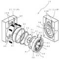
図1は流量センサーの一例を示す全体縦断面図、図2は図1の流量センサーの分解斜視図、図3は荷重差センサーに変位制限部材を設けた例を示す縦断面図、図4は請求項1の発明に係る流量センサーの実施例を示す縦断面図、図5は他の流量センサーの実施例を示す縦断面図、図6は請求項2の発明に係る流量センサーの実施例を示す縦断面図、図7は請求項3及び4の発明に係る流量センサーの実施例を示す縦断面図、図8は流量センサーにおいて大流量の流体を測定する実施例を示す概略断面図、図9は同じく流量センサーにおいて大流量の流体を測定する他の実施例を示す概略断面図である。
【0012】
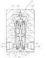
図1ないし図3に図示した流量センサー10は、前記した超純水や薬液等の微量な流量の測定に使用されるもので、チャンバ20内を流通する流体の圧力変動を2つの第一及び第二ダイヤフラム31,32で受圧し、荷重差センサー50でその荷重差を変位量として検出して流体の流量を検知するようにしたものである。
【0013】
特に、この流量センサー10では、前記第一ダイヤフラム31及び第二ダイヤフラム32が受ける流体の圧力変動によって生ずる変位量が一定以上の大きさにならないように前記ダイヤフラム31,ダイヤフラム32(図1及び図2参照)又は荷重差センサー50(図3参照)に対して変位制限部材61,62(図1,2)、66,67(図3)を設けたことを特徴とするものである。なお、変位制限部材は必ずしも一次側及び二次側両側の流体の圧力変動に対して設けられることを必要とせず、一側(通常一次側)の流体の圧力変動に対してのみ設けてもよいものである。
【0014】
チャンバ20は、図のように、前記チャンバ20内に対向配置された2つの第一ダイヤフラム31,第二ダイヤフラム32によって、第一ダイヤフラム31に面する一次側チャンバ21と、第二ダイヤフラム32に面する二次側チャンバ25に区画され、前記一次側チャンバ21からオリフィス部40を有するバイパス流路35を経て二次側チャンバ25に差圧を生じさせた流体が流通される。チャンバ20には、その一側(一次側チャンバ21)に開口する流入口23を有する被測定流体の流入部22と、他側(二次側チャンバ25)に開口する流出口27を有する被測定流体の流出部26が形成されている。
【0015】
第一ダイヤフラム31及び第二ダイヤフラム32は、この実施例では耐蝕性に優れるポリテトラフルオロエチレン(PTFE樹脂)等のフッ素樹脂より形成されている。なお、図の符号33,34は第一ダイヤフラム31及び第二ダイヤフラム32を固定する内周押えリング、36,37は同じく外周押えリングである。
【0016】
この流量センサー10では、前記第一ダイヤフラム31及び第二ダイヤフラム32が受ける流体の圧力変動によって生ずる変位量が一定以上の大きさにならないように、前記ダイヤフラム31,32又は荷重差センサー50に対して、変位制限部材61,62、66,67が設けられている。図1及び図2の実施例では、各ダイヤフラム31,32に対して変位制限部材61,62が設けられ、図3の実施例では各ダイヤフラム31,32に対して変位制限部材66,67が設けられている。なお、図3において、図1,2と共通符号は同一構成部材を表す。
【0017】
まず、図1及び図2の例について説明すると、ここでは、ダイヤフラム31,32に対して変位制限部材61,62が設けられ、特にこの例では、各ダイヤフラム31,32の圧力を受けその荷重を伝達する受圧部71,72の内側に、変位制限部材61,62が設けられている。
すなわち、この例では、荷重差センサー50が前記チャンバ20内に固定配置された外周枠部51と中心側の中心部材52と前記外周枠部51と中心部材52の間に延設され計測部Gが設けられた起歪部55とを含んでおり、この荷重差センサー50の中心部材52に各ダイヤフラム31,32の圧力を受けその荷重を伝達する受圧部71,72が取り付けられている。符号53,54は荷重差センサー50の中心部材52に各受圧部71,72と一体に取り付けるために形成された結合凸部である。
【0018】
ちなみに、実施例の荷重差センサー50はいわゆる歪みセンサーと呼ばれるもので、軟鋼、ステンレス鋼あるいはアルミニウム等の弾性体よりなり、チャンバ20に固定された外周枠部51と各ダイヤフラム31,32の圧力を受ける受圧部71,72が取り付けられた中心部材52との間に延設された起歪部55に生ずる変位量を該起歪部55に設けた計測部(ゲージ部)Gによってその機械的歪みを電気信号として取り出すものである。すなわち、オリフィス40によって生ずる流体の圧力差を第一ダイヤフラム31と第二ダイヤフラム32に加わる荷重差ΔP(kPa)の変位量として検出して、該変位量の大きさを電気信号I(mA)に変換して流量(ml/min)の計測を行う。この実施例では起歪部55は薄面の十字状に形成したもの(図2参照)を用いたが、全面状のものであってもよい。
【0019】
受圧部71,72は、好ましくはダイヤフラム31,32と同じ耐蝕性に優れるポリテトラフルオロエチレン(PTFE樹脂)等のフッ素樹脂より形成されている。そして、請求項3の発明として規定したように、変位制限部材61,62をこの受圧部71,72の内側に配置することが製造上及び構成上便宜であり、またダイヤフラム31,32の保護にもなる。符号73,74は荷重差センサー50の中心部材52の結合凸部53,54を取り付けるため凹部である。なお、受圧部71,72はダイヤフラム31,32と一体に形成してもよい。
【0020】
変位制限部材61,62は、ダイヤフラム31,32の変位が所定以上の大きさにならないようにたわみ方向にストッパとして機能するもので、そのような機能を果たすものであればなんでもよい。この実施例では金属製のリング状物よりなり(図2参照)、その外周縁部63,64が荷重差センサー50の外周枠部51に嵌着されることによってチャンバ20に固定されている。なお、変位制限部材は一側の流体の圧力変動に対してのみ設けることもできる。
【0021】
変位制限部材61,62によってダイヤフラム31,32の変位が制限される間隔、つまりストッパ間隙aは差圧感度やダイヤフラム31,32の弾性限界等を考慮して決定される。通常3kgf程度までの荷重を測定するには、ダイヤフラム31,32の変位制限量、つまりストッパ間隙aは0.3mm程度とすればよく、この実施例では0.5mmに設定されている。
【0022】
バイパス流路35は、図示のように、一次側チャンバ21に開口するバイパス入口から前記二次側チャンバ25に開口するバイパス出口に至る流路で、該バイパス流路35の途中にオリフィス(部)40が介装される。オリフィス40は、図のように、単独部材として交換自在に配置してもよいが、必要によりボディ本体11と一体に形成してもよい。オリフィス40は所定径の孔部41を有していて、前記バイパス流路35内に介装されることによって、その前後に差圧を生じさせる。
【0023】
なお、本体ボディ11は、実施例ではその用途との関係から耐蝕性に優れるポリテトラフルオロエチレン(PTFE樹脂)等のフッ素樹脂から形成されているが、一般的なプラスチックあるいは金属によって形成することもできる。本体ボディ11は、図のように、半割形状のボディ部材11A及び11B(ならびに必要ならば中間ブロック)の組合体よりなり、図示しない取付部材によって一体に締付合着される。
【0024】
図2において符号S1,S2は荷重差センサー50の起歪部55に設けられた計測部(ゲージ部)Gのリード線で、ボディ部材11の切欠12A及び12Bを介して外部の電圧計等の表示装置、コンピューター等の演算処理装置あるいは各種制御装置等に接続される。
【0025】
図3では、荷重差センサー50に対して変位制限部材66,67が設けられた例が示される。ここでは、荷重差センサー50の中心部材52に対して、前記したと同様の金属製のリング状物よりなる変位制限部材66,67が設けられている。図3の符号68,69は外周縁部を表し、この外周縁部68,69が荷重差センサー50の外周枠部51に嵌着されることによってチャンバ20に固定されている。なお、前記と同様に、変位制限部材は一側の流体の圧力変動に対してのみ設けることもできる。
【0026】
この種流量センサー10で測定される流体には、フッ酸や、アンモニア水など、透過もしくは浸透しやすい流体も多く存在する。このため、以下に説明し図4ないし図6に示す流量センサー10A,10B,10Cのように、前記流体のガス等から荷重差センサーの計測部Gを保護する構造が提案される。なお、以下の実施例において、図1ないし図3における同一構成部材については、同一符号を付してその説明を省略する。
【0027】
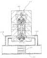
まず、請求項1の発明に係る流量センサーとして、荷重差センサーの計測部が設けられた起歪部の外側に保護ダイヤフラムが形成されたことを特徴とするものが提案される。実施例では、図4に示す流量センサー10Aのように、前記受圧部81,85と変位制限部材82,86が保護ダイヤフラム部83,87で一体に結合された構造が示される。この構造によれば、荷重差センサー50の起歪部55に設けられた計測部Gが、前記受圧部81,85及び変位制限部材82,86間の保護ダイヤフラム部83,87によって、チャンバ21,25を流通する流体から完全に遮断され、前記浸透ガス等による不具合を防止することができる。なお、保護ダイヤフラム部83,87は、前記荷重差センサー50の起歪部55同様に可撓性を有するものであるため、当然第一ダイヤフラム31及び第二ダイヤフラム32からの圧力変動の伝達を妨げるものではない。
【0028】
また、図5に示す流量センサー10Bでは、前記荷重差センサー本体50がその両側を保護ダイヤフラム部91,96を有する2個のホイール部材90,95によって挟持されていることを特徴としている。該ホイール部材90,95は、荷重差センサー50の起歪部55に対応する位置に保護ダイヤフラム部91,96を有するとともに、中心部材52位置に該中心部材52及び受圧部71,72との固定部92,97を有している。これによって荷重差センサー50の起歪部55に取り付けられた計測部Gは、両側を前記ホイール部材90,95の保護ダイヤフラム部91,96によりチャンバ21,25から遮断されガス等から保護することができる。
【0029】
さらに、図6に示す流量センサー10Cは、請求項2に係るもので、前記荷重差センサーの起歪部が2つ対向して形成されていて前記計測部Gが前記各起歪部の内面側に設けられていることを特徴とするものである。実施例では、荷重差センサー100が第1部材101と第2部材105の2部材から構成される。この荷重差センサー100は、前記第1部材101及び第2部材105を隣接させ、それぞれの起歪部102,106の内面側にセンサー計測部Gを取り付けることにより、チャンバ21,25を流通する流体からのガスを避けることができる。
【0030】
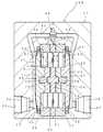
さらにまた図7に示す流量センサー10Dでは、請求項3及び4に係るもので、ボディ本体に、前記ダイヤフラム部の背面側空間110と連通するパージ用気体の流入部111及び流出部115が設けられていて、前記ダイヤフラム部の背面側空間110に前記透過ガスが存在する場合には外部へ排出することによりセンサー計測部Gをガスから保護する。なお、該実施例においては、荷重差センサー50の外周枠部51の所定位置に前記パージ用気体の流入部111及び流出部115に連通する貫通孔56を設けた。
【0031】
すなわち、パージ用気体の流入部111からダイヤフラム部31,32の背面側空間110内にパージ用気体(空気や窒素ガス等)を流入し、パージ用気体の流出部115から流出することによって背面側空間110の流体からの透過ガスを排出するのである。この実施例では、図示のように、一次側チャンバ21のダイヤフラム31と二次側チャンバ22のダイヤフラム32の背面側空間110が共通となっているため、前記パージ用気体の流入部111及び流出部115からの流路112及び116はいずれも荷重差センサー50の外周枠部51の貫通孔56に接続されている。もちろん、これらの流路112及び116はダイヤフラム部31,32の背面側空間110と直接連通してもよいことはいうまでもない。
【0032】
パージ用気体の流出部115からパージ用気体とともに流出した透過ガスは、配管120を介して該流量センサー10外の所定排出先に送り込まれ、必要により図示しない公知の処理装置を経て廃棄される。これによって、作業環境の悪化や周辺の空気汚染等を防止することが可能となる。
【0033】
さらに、請求項6の発明として規定したように、前記パージ用気体の流出部115側の配管120にガス濃度又は液漏れを検知する手段125を配置してもよい。これによって、ダイヤフラム部31,32の背面側空間110の透過ガス量の変移や液漏れ等の状態を検知することができる。被制御流体の流通状況やダイヤフラム部の状態も知ることができる。なお、ガス濃度又は液漏れを検知する手段としては公知の検知機器を用いることができる。
【0034】
上に述べた実施例の流量センサー10(10A,10B,10C,10D)にあっては、各ダイヤフラム31,32がチャンバ21,25における流体の圧力変動を受け、受圧部71,72(81,85)に伝達する。該受圧部71,72(81,85)の受けた圧力変動によって生ずる荷重を、荷重差センサー50(100)の起歪部55(91,96)におけるセンサー計測部Gによって、変位量の差として検出して流体の流量を検知する。また、流体に大きな圧力変動があった場合に、ダイヤフラム31,32が大きく変位しようとしても、該受圧部71,72(81,85)の外周が変位制限部材61,62(82,86)に当接して、その変位量を規制することにより、ダイヤフラム31,32や荷重センサー50(100)の計測範囲能力を大幅に超えることを防ぐ。
【0035】
前記流量センサー10(10A,10B,10C,10D)を用いて、流体の計測を行ったところ、最大計測差圧を20KPaに設定したとき、0.2KPa(20mmH2O)の計測をすることができた。また、このときの耐圧力は300KPaを確保することができるとともに、流量は50ml/min.〜5ml/min.の範囲で計測可能となる。
【0036】
また、この流量センサー10(10A,10B,10C,10D)では、一次側チャンバ21と二次側チャンバ25の差圧が小さくても計測が可能であることにより、オリフィス40の径を大きく設定することが可能となり、ひいては例えば半導体CMP用のスラリー液のような詰まりやすい液体でも連続で計測することが可能となった。そのときの流量範囲としては、500ml/min.〜50ml/min.を可能とする。
【0037】
さらにまた、大流量の流体を測定する場合には、図8に示すこの流量センサー10Eのように、大径管部131に大径のオリフィス135を設け、大径管部131より分岐した小径管部132より前記流量センサー10本体の一次側チャンバ21に接続することによって、流体の流れを妨げることなく効率よく測定することができる。また、この実施例は大径管を流量センサー10E内に一体に組み込んだものであるが、図9に示すように、前記大径管部131を独立した別配管とし、その傍らに小径管132により流量センサー10をバイパスとして設けたものとしてもよい。
【0038】
【発明の効果】
以上図示し説明したように、この発明の流量センサーによれば、前記第一ダイヤフラム及び第二ダイヤフラムが受ける流体の圧力変動によって生ずる変位量が一定以上の大きさにならないようにダイヤフラム又は荷重差センサーに対して変位制限部材を設けたものであるから、流量計測における差圧感度を高めながら、かつ高い流体耐圧を有する。これによって、微差圧、すなわち微少流量(10ml/min以下)の計測が可能になるとともに、流量計測範囲をも広く(10倍も容易)することができる。
【0039】
とともに、この発明構造によれば、荷重差センサーの計測部がチャンバから確実に隔離又は遮断された構造であるため、被計測流体がフッ酸、アンモニア水等の浸透もしくは透過しやすい流体の場合にあっても、透過してくるガス等から保護される。
【図面の簡単な説明】
【図1】 流量センサーの一例を示す全体縦断面図である。
【図2】図1の流量センサーの分解斜視図である。
【図3】 荷重差センサーに変位制限部材を設けた例を示す縦断面図である。
【図4】請求項1の発明に係る流量センサーの実施例を示す縦断面図である。
【図5】他の流量センサーの実施例を示す縦断面図である。
【図6】請求項2の発明に係る流量センサーの実施例を示す縦断面図である。
【図7】請求項3及び4の発明に係る流量センサーの実施例を示す縦断面図である。
【図8】 流量センサーにおいて大流量の流体を測定する実施例を示す概略断面図である。
【図9】 流量センサーにおいて大流量の流体を測定する他の実施例を示す概略断面図である。
【符号の説明】
10,10A,10B,10C,10D,10E 流量センサー
11 本体ボディ
20 チャンバ
21 一次側チャンバ
22 流入部
23 流入口
25 二次側チャンバ
26 流出部
27 流出口
31 第一ダイヤフラム
32 第二ダイヤフラム
35 バイパス流路
40 オリフィス
50,100 荷重差センサー
51 外周枠部
52 中心部材
55、102,106 起歪部
61,62、66,67 変位制限部材
71,72、81,85 受圧部
83,87、91,96 保護ダイヤフラム部
90 ホイール部材
110 ダイヤフラム背面側空間部
111 パージ用気体の流入部
115 パージ用気体の流出部
G センサー計測部[0001]
BACKGROUND OF THE INVENTION
The present invention relates to a fluid flow sensor, and more particularly, to a flow sensor using a diaphragm.
[0002]
[Prior art]
As a means of measuring the flow rate of fluid, it is common practice to calculate the pressure of each pressure sensor using two pressure sensors across an orifice, but there are significant problems in terms of sensitivity and pressure resistance. . That is, in this method, when the downstream portion of the flow sensor is blocked, a large pressure is applied, so that a pressure sensor with a high withstand pressure is inevitably required, and the sensitivity is further lowered. In addition, since two sensors are used, drift characteristics (temperature, power supply voltage, etc.) due to individual differences of pressure sensors are different, and there is a problem that correction and zero adjustment must be frequently performed after calculation.
[0003]
On the other hand, the present inventor previously proposed Japanese Patent No. 3184126 as a flow sensor for ultrapure water, chemicals, and the like used in a semiconductor manufacturing process, for example. This flow sensor defines a primary side chamber and a secondary side chamber by a first diaphragm and a second diaphragm, and connects the primary side chamber and the secondary side chamber by a bypass flow path, and an orifice is connected to the bypass flow path. A displacement caused by pressure fluctuations of fluid received by the first diaphragm and the second diaphragm is detected by a strain gauge.
[0004]
The above-mentioned patent does not have a movable member (such as an impeller or float) for detecting the flow rate in the flow path of the fluid to be measured, so there is no possibility of generating fine dust (particles), and measurement of ultrapure water or chemicals In addition, since the change in the flow rate can be directly obtained as an electrical signal, the subsequent control is easy. In particular, since an orifice (part) is interposed in the bypass flow path, the diameter of the orifice can be arbitrarily set, and the diameter can be made extremely small for detection of a very small amount of flow. When an independent member is used, it can be exchanged according to the orifice diameter.
[0005]
However, even in the above-described patent structure, the sensitivity of the load difference sensor (strain gauge) must be increased when measuring the minute differential pressure of the flow rate. However, if the thickness of the movable part is reduced in order to increase the sensitivity of the load difference sensor, if the primary or secondary side is accidentally applied with a high pressure or the flow rate is too high, the load will be overloaded. There was a problem that the elastic limit of the differential sensor moving part was exceeded and it was damaged or could not return to the zero point. On the other hand, if the pressure resistance strength of the movable part of the load difference sensor is increased, the differential pressure sensitivity of the flow rate becomes dull, the rangeability of the flow rate measurement range cannot be increased, and the pressure in the chamber can be reduced by reducing the orifice diameter. If the loss is not increased, there is a problem such as poor accuracy.
[0006]
[Problems to be solved by the invention]
The present invention, in view of the situation as above, with an easy measurement of the fine pressure difference at the time of small flow rate measurement,Ri high breakdownder, together, to protect the measuring unit from thegas and the like of the fluid It is intended to provide a flow sensor structure that can be used.
[0007]
[Means for Solving the Problems]
That is, in the first aspect of the present invention, two first and second diaphragms are opposed to each other in the chamber, and are divided into a primary chamber facing the first diaphragm and a secondary chamber facing the second diaphragm. A fluid having a differential pressure is circulated from the primary side chamber to the secondary side chamber via a bypass flow path having an orifice, and the load difference sensor disposed between the first diaphragm and the second diaphragm The load difference caused by the pressure fluctuation of the fluid received by the first diaphragm and the second diaphragm is detected as a displacement amount to detect the flow rate of the fluid, and the displacement amount caused by the fluid pressure fluctuation received by the diaphragm is constant.Ru provided a displacement restriction member relative to the diaphragm or load difference sensor so as not more than the sizeBoth according to the flow sensor, characterized in thatto form a protective diaphragm portion on the outer side of the strain generating portion measuring portion of the load difference sensor is provided.
[0008]
The invention of
[0009]
Furthermore, the invention of
[0010]
Furthermore, the invention according to
[0011]
DETAILED DESCRIPTION OF THE INVENTION
Hereinafter, the present invention will be described in detail with reference to the accompanying drawings.
1 isan overall longitudinal sectional viewshowing an example of a flow sensor, FIG. 2 is an exploded perspective view of the flow sensor of FIG. 1, FIG. 3 isa longitudinal sectional viewshowing anexample in which a displacement limiting member is provided on a load difference sensor, and FIG. longitudinal sectional view showing an embodiment of a flow sensoraccording to the invention of
[0012]
The
[0013]
In particular, in the
[0014]
As shown in the figure, the
[0015]
In this embodiment, the first diaphragm 31 and the second diaphragm 32 are made of a fluororesin such as polytetrafluoroethylene (PTFE resin) having excellent corrosion resistance. In addition, the code |
[0016]
In the
[0017]
First, theexample of FIGS. 1 and 2 will be described. Here, displacement limiting members 61 and 62 are provided for the diaphragms 31 and 32. In particular, in this example, the pressures of the diaphragms 31 and 32 are received and the loads are applied. Displacement limiting members 61 and 62 are provided inside the pressure receiving portions 71 and 72 for transmission.
That is, in this example, the
[0018]
Incidentally, the
[0019]
The pressure receiving portions 71 and 72 are preferably made of a fluororesin such as polytetrafluoroethylene (PTFE resin) that has the same corrosion resistance as the diaphragms 31 and 32. As defined in the third aspect of the invention, it is convenient in terms of manufacturing and construction to dispose the displacement limiting members 61 and 62 inside the pressure receiving portions 71 and 72, and to protect the diaphragms 31 and 32. Also become.
[0020]
The displacement limiting members 61 and 62 function as a stopper in the deflection direction so that the displacement of the diaphragms 31 and 32 does not become larger than a predetermined value, and any members that fulfill such a function may be used. In this embodiment, it is made of a metal ring-like material (see FIG. 2), and its outer
[0021]
The interval at which the displacement of the diaphragms 31 and 32 is limited by the displacement limiting members 61 and 62, that is, the stopper gap a is determined in consideration of the differential pressure sensitivity, the elastic limit of the diaphragms 31 and 32, and the like. In order to measure the load up to about 3 kgf, the displacement limit amount of the diaphragms 31 and 32, that is, the stopper gap a should be about 0.3 mm. In this embodiment, it is set to 0.5 mm.
[0022]
As shown in the figure, the
[0023]
In addition, although the
[0024]
In FIG. 2, reference numerals S <b> 1 and S <b> 2 are lead wires of a measuring part (gauge part) G provided in the strain generating part 55 of the
[0025]
FIG. 3 shows an example in which displacement limiting members 66 and 67 are provided for the
[0026]
There are many fluids that can be easily permeated or permeated, such as hydrofluoric acid and ammonia water, as fluids measured by the
[0027]
First, a flow rate sensor according to thefirst aspect of the invention is proposed in which a protective diaphragm is formed outside a strain generating portion provided with a measurement portion of a load difference sensor. In the embodiment, a structure in which the pressure receiving portions 81 and 85 and the
[0028]
Further, the flow sensor 10B shown in FIG. 5 is characterized in that the load difference sensor
[0029]
Furthermore, the flow rate sensor 10C shown in FIG. 6 is according to
[0030]
Furthermore, in the flow rate sensor 10D shown in FIG. 7, the body main body is provided with an inflow portion 111 and an outflow portion 115 for purging gas communicating with the back side space 110 of the diaphragm portion. If the permeate gas is present in the back side space 110 of the diaphragm part, the sensor measurement part G is protected from the gas by discharging it to the outside. In this embodiment, a through hole 56 communicating with the inflow portion 111 and the outflow portion 115 of the purge gas is provided at a predetermined position of the outer
[0031]
That is, the purge gas (air, nitrogen gas, or the like) flows from the purge gas inflow portion 111 into the back surface space 110 of the diaphragm portions 31 and 32 and flows out of the purge gas outflow portion 115, thereby causing the rear surface side. The permeated gas from the fluid in the space 110 is discharged. In this embodiment, as shown in the drawing, since the rear side space 110 of the diaphragm 31 of the primary chamber 21 and the diaphragm 32 of the
[0032]
The permeate gas flowing out together with the purge gas from the purge gas outflow portion 115 is sent to a predetermined discharge destination outside the
[0033]
Further, as defined in the invention of
[0034]
In the flow sensor 10 (10A, 10B, 10C, 10D) of the above-described embodiment, the diaphragms 31, 32 are subjected to fluid pressure fluctuations in the
[0035]
When the fluid is measured using the flow rate sensor 10 (10A, 10B, 10C, 10D), when the maximum differential pressure is set to 20 KPa, the measurement may be 0.2 KPa (20 mmH2 O). did it. In addition, the pressure resistance at this time can ensure 300 KPa, and the flow rate is 50 ml / min. ~ 5 ml / min. It becomes possible to measure in the range.
[0036]
Further, in the flow rate sensor 10 (10A, 10B, 10C, 10D), the diameter of the
[0037]
Furthermore, when measuring a fluid with a large flow rate, a small-diameter pipe branched from the large-diameter pipe part 131 is provided with a large-diameter orifice 135 in the large-diameter pipe part 131 as in the flow sensor 10E shown in FIG. By connecting the unit 132 to the primary chamber 21 of the main body of the
[0038]
【The invention's effect】
As illustrated and described above, according to the flow sensor of the present invention, the diaphragm or load difference sensor prevents the displacement generated by the pressure fluctuation of the fluid received by the first diaphragm and the second diaphragm from exceeding a certain level. Since the displacement limiting member is provided, the differential pressure sensitivity in the flow rate measurement is increased and the fluid pressure resistance is high. As a result, it is possible to measure a minute differential pressure, that is, a minute flow rate (10 ml / min or less), and to widen the flow rate measurement range (10 times easier).
[0039]
At the same time, according to the structure ofthe present invention, since the measurement unit of the load difference sensor is reliably isolated or cut off from the chamber, the fluid to be measured is a fluid that easily permeates or permeates hydrofluoric acid, ammonia water, or the like. Even if it exists, it is protected from the permeating gas and the like.
[Brief description of the drawings]
FIG. 1is an overall longitudinal sectional viewshowing an example of a flow sensor.
FIG. 2 is an exploded perspective view ofthe flow sensor of FIG.
FIG. 3is a longitudinal sectional viewshowing anexample in which a displacement limiting member is provided in a load difference sensor.
FIG. 4 is a longitudinal sectional view showing an embodiment of a flow sensor according to theinvention of
FIG. 5 is a longitudinal sectional view showinganother embodimentof the flow sensor.
6 is a longitudinal sectional view showing an embodiment of a flow sensor according to theinvention of
FIG. 7 is a longitudinal sectional view showing an embodiment of a flow sensor accordingto the third and fourth aspects of the invention.
FIG. 8 is a schematic cross-sectional view showing an example of measuring a large flow rate fluid in the flow rate sensor.
FIG. 9 is a schematic cross-sectional view showing another embodiment for measuring a large flow rate fluid in the flow rate sensor.
[Explanation of symbols]
10, 10A, 10B, 10C, 10D,
Claims (4)
Translated fromJapanese前記ダイヤフラムが受ける流体の圧力変動によって生ずる変位量が一定以上の大きさにならないように前記ダイヤフラム又は荷重差センサーに対して変位制限部材を設けるとともに、前記荷重差センサーの計測部が設けられた起歪部の外側に保護ダイヤフラム部を形成したことを特徴とする流量センサー。Two first and second diaphragms are opposed to each other in the chamber, and are divided into a primary side chamber facing the first diaphragm and a secondary side chamber facing the second diaphragm, and an orifice portion is formed from the primary side chamber. A fluid that has caused a differential pressure in the secondary chamber is circulated through a bypass flow path, and the first diaphragm and the second diaphragm are received by a load difference sensor disposed between the first diaphragm and the second diaphragm. In what detects the flow difference of the fluid by detecting the load difference caused by the pressure fluctuation of the fluid as the displacement amount,
Rutotomoni provided a displacement restriction member relative to the diaphragm or load difference sensor to displacement is not above a certain size caused by pressure fluctuations of the fluid in which the diaphragm issubjected, the measurement unit of the load difference sensor is provided A flow sensor characterized inthat aprotective diaphragm part is formed outside the strain generating part .
前記ダイヤフラムが受ける流体の圧力変動によって生ずる変位量が一定以上の大きさにならないように前記ダイヤフラム又は荷重差センサーに対して変位制限部材を設けるとともに、前記荷重差センサーの計測部が設けられた起歪部外側に保護ダイヤフラム部を形成したことを特徴とする流量センサー。The flow rate sensor according to claim3, wherein means for detecting gas concentration or liquid leakage is arranged in the piping system on the purge gas outflow portion side.
Totomoni Keru set the Hen'i limiting member Nitaishite said diaphragm or load Sa Sensa so as not Hen'i Ryo that Shozuru Niyotte pressure fluctuations of the fluid in which the diaphragm is received by above a certain Okiof, the measurement unit of the load Sa sensor was provided A flow sensor characterized inthat a protective diaphragm part is formed outside the strain generating part .
Priority Applications (6)
| Application Number | Priority Date | Filing Date | Title |
|---|---|---|---|
| JP2002358342AJP3845615B2 (en) | 2002-03-12 | 2002-12-10 | Flow sensor |
| TW091136404ATWI254127B (en) | 2002-03-12 | 2002-12-17 | Flow rate sensor |
| KR10-2003-0003228AKR20030074125A (en) | 2002-03-12 | 2003-01-17 | Flow sensor |
| CNB031034810ACN100510653C (en) | 2002-03-12 | 2003-01-30 | Flow sensor |
| US10/368,376US6640650B2 (en) | 2002-03-12 | 2003-02-20 | Flow rate sensor |
| EP03005526AEP1345011A3 (en) | 2002-03-12 | 2003-03-11 | Flow rate sensor |
Applications Claiming Priority (3)
| Application Number | Priority Date | Filing Date | Title |
|---|---|---|---|
| JP2002-66722 | 2002-03-12 | ||
| JP2002066722 | 2002-03-12 | ||
| JP2002358342AJP3845615B2 (en) | 2002-03-12 | 2002-12-10 | Flow sensor |
Publications (3)
| Publication Number | Publication Date |
|---|---|
| JP2003337053A JP2003337053A (en) | 2003-11-28 |
| JP2003337053A5 JP2003337053A5 (en) | 2004-12-02 |
| JP3845615B2true JP3845615B2 (en) | 2006-11-15 |
Family
ID=27767224
Family Applications (1)
| Application Number | Title | Priority Date | Filing Date |
|---|---|---|---|
| JP2002358342AExpired - LifetimeJP3845615B2 (en) | 2002-03-12 | 2002-12-10 | Flow sensor |
Country Status (6)
| Country | Link |
|---|---|
| US (1) | US6640650B2 (en) |
| EP (1) | EP1345011A3 (en) |
| JP (1) | JP3845615B2 (en) |
| KR (1) | KR20030074125A (en) |
| CN (1) | CN100510653C (en) |
| TW (1) | TWI254127B (en) |
Cited By (1)
| Publication number | Priority date | Publication date | Assignee | Title |
|---|---|---|---|---|
| JP2009229444A (en)* | 2008-02-26 | 2009-10-08 | Advance Denki Kogyo Kk | Flow rate measurement device |
Families Citing this family (41)
| Publication number | Priority date | Publication date | Assignee | Title |
|---|---|---|---|---|
| US20080073610A1 (en)* | 1997-08-22 | 2008-03-27 | Manning Casey P | Stopcock valve |
| CA2524632A1 (en)* | 2003-04-01 | 2004-10-21 | The J.M. Smucker Company | Process for adding microbiologically safe chocolate particulates to yogurt |
| JP2005274265A (en)* | 2004-03-24 | 2005-10-06 | Nippon M K S Kk | Flowmeter |
| US7546772B2 (en)* | 2004-12-30 | 2009-06-16 | Honeywell International Inc. | Piezoresistive pressure sensor |
| US7644632B2 (en)* | 2005-01-15 | 2010-01-12 | Best John W | Viscometric flowmeter |
| JP2006322783A (en)* | 2005-05-18 | 2006-11-30 | Dainippon Screen Mfg Co Ltd | Pressure sensor and substrate processing apparatus |
| US9146564B2 (en) | 2006-03-06 | 2015-09-29 | Deka Products Limited Partnership | Product dispensing system |
| US7905373B2 (en) | 2006-03-06 | 2011-03-15 | Deka Products Limited Partnership | System and method for generating a drive signal |
| US11214476B2 (en) | 2006-03-06 | 2022-01-04 | Deka Products Limited Partnership | System and method for generating a drive signal |
| US11906988B2 (en) | 2006-03-06 | 2024-02-20 | Deka Products Limited Partnership | Product dispensing system |
| US7965486B2 (en)* | 2006-10-24 | 2011-06-21 | The Johns Hopkins University | Arc flash detection system |
| US7472608B2 (en)* | 2007-04-04 | 2009-01-06 | Rosemount Inc. | Flangeless differential pressure transmitter for industrial process control systems |
| MX2010002673A (en)* | 2007-09-06 | 2010-06-01 | Deka Products Lp | Product dispensing system. |
| US10562757B2 (en) | 2007-09-06 | 2020-02-18 | Deka Products Limited Partnership | Product dispensing system |
| US11634311B2 (en) | 2007-09-06 | 2023-04-25 | Deka Products Limited Partnership | Product dispensing system |
| US8314740B2 (en) | 2007-09-06 | 2012-11-20 | Deka Products Limited Partnership | RFID system |
| BRPI0817076A2 (en)* | 2007-09-06 | 2015-03-24 | Deka Products Lp | System and processing method |
| WO2009033087A1 (en) | 2007-09-06 | 2009-03-12 | Deka Products Limited Partnership | Rfid system and method |
| US10859072B2 (en) | 2007-09-06 | 2020-12-08 | Deka Products Limited Partnership | Product dispensing system |
| US12135019B2 (en) | 2007-09-06 | 2024-11-05 | Deka Products Limited Partnership | Product dispensing system |
| WO2009143289A2 (en) | 2008-05-20 | 2009-11-26 | Deka Products Limited Partnership | Rfid system |
| JP5213582B2 (en)* | 2008-08-18 | 2013-06-19 | アドバンス電気工業株式会社 | Flow measuring device |
| AU2009285598B2 (en)* | 2008-08-28 | 2015-07-02 | Deka Products Limited Partnership | Product dispensing system |
| EP2539961B1 (en)* | 2010-02-26 | 2016-06-29 | DEKA Products Limited Partnership | Rfid system with an eddy current trap |
| WO2012049742A1 (en) | 2010-10-13 | 2012-04-19 | 日立オートモティブシステムズ株式会社 | Flow sensor and production method therefor, and flow sensor module and production method therefor |
| JP3168588U (en)* | 2011-04-08 | 2011-06-16 | アドバンス電気工業株式会社 | Fluid supply control device |
| US8985396B2 (en) | 2011-05-26 | 2015-03-24 | Pepsico. Inc. | Modular dispensing system |
| US8746506B2 (en) | 2011-05-26 | 2014-06-10 | Pepsico, Inc. | Multi-tower modular dispensing system |
| JP6092044B2 (en) | 2013-08-19 | 2017-03-08 | ミネベアミツミ株式会社 | Load sensor unit |
| CN104043168B (en)* | 2014-06-27 | 2016-05-04 | 计宁翔 | Exhalation differential pressure flow sensor automatic cleaning apparatus |
| RU2725538C2 (en)* | 2015-01-30 | 2020-07-02 | Анхойзер-Буш Инбев С.А. | Methods, devices and systems for production of a beverage from the main liquid and ingredient |
| AU2016210828B2 (en) | 2015-01-30 | 2020-09-03 | Anheuser-Busch Inbev S.A. | Pressurized beverage concentrates and appliances and methods for producing beverages therefrom |
| DE102015216624A1 (en) | 2015-08-31 | 2017-03-02 | Siemens Aktiengesellschaft | Pressure sensor arrangement and transmitter for process instrumentation with such a pressure sensor arrangement |
| US11662279B2 (en) | 2016-08-15 | 2023-05-30 | Veltek Associates, Inc. | Portable air sampler |
| US10732081B2 (en)* | 2016-08-15 | 2020-08-04 | Veltek Associates, Inc. | Portable air sampler |
| US11135345B2 (en) | 2017-05-10 | 2021-10-05 | Fresenius Medical Care Holdings, Inc. | On demand dialysate mixing using concentrates |
| DE112018000081B4 (en)* | 2017-08-09 | 2024-02-01 | Ckd Corporation | FLOW METER |
| DE102018215851B3 (en)* | 2018-09-18 | 2019-09-26 | Siemens Aktiengesellschaft | Pressure or flow cell |
| US11504458B2 (en) | 2018-10-17 | 2022-11-22 | Fresenius Medical Care Holdings, Inc. | Ultrasonic authentication for dialysis |
| CN111272332B (en)* | 2020-03-11 | 2022-01-04 | 电子科技大学 | A Differential Pressure Sensor Based on Optical Fiber Point Sensor |
| US12181328B2 (en)* | 2020-04-17 | 2024-12-31 | Illinois Tool Works Inc. | Flow through pressure sensor structured to remove dead volume |
Family Cites Families (6)
| Publication number | Priority date | Publication date | Assignee | Title |
|---|---|---|---|---|
| US3372594A (en)* | 1966-04-11 | 1968-03-12 | Gen Electric | Compensation system for differential pressure measuring device |
| US4221134A (en)* | 1979-08-20 | 1980-09-09 | Ekstrom Jr Regner A | Differential pressure transducer with strain gauge |
| EP0874976B1 (en)* | 1996-01-17 | 2002-04-10 | Micro Motion Incorporated | Bypass type flowmeter |
| US5796007A (en)* | 1996-09-23 | 1998-08-18 | Data Instruments, Inc. | Differential pressure transducer |
| US6550337B1 (en)* | 2000-01-19 | 2003-04-22 | Measurement Specialties, Inc. | Isolation technique for pressure sensing structure |
| AU2001257307A1 (en)* | 2000-04-26 | 2001-11-07 | The Foxboro Company | Differential pressure sensor device having over pressure protection |
- 2002
- 2002-12-10JPJP2002358342Apatent/JP3845615B2/ennot_activeExpired - Lifetime
- 2002-12-17TWTW091136404Apatent/TWI254127B/ennot_activeIP Right Cessation
- 2003
- 2003-01-17KRKR10-2003-0003228Apatent/KR20030074125A/ennot_activeCeased
- 2003-01-30CNCNB031034810Apatent/CN100510653C/ennot_activeExpired - Fee Related
- 2003-02-20USUS10/368,376patent/US6640650B2/ennot_activeExpired - Lifetime
- 2003-03-11EPEP03005526Apatent/EP1345011A3/ennot_activeWithdrawn
Cited By (1)
| Publication number | Priority date | Publication date | Assignee | Title |
|---|---|---|---|---|
| JP2009229444A (en)* | 2008-02-26 | 2009-10-08 | Advance Denki Kogyo Kk | Flow rate measurement device |
Also Published As
| Publication number | Publication date |
|---|---|
| EP1345011A2 (en) | 2003-09-17 |
| US20030172744A1 (en) | 2003-09-18 |
| TW200303981A (en) | 2003-09-16 |
| TWI254127B (en) | 2006-05-01 |
| JP2003337053A (en) | 2003-11-28 |
| US6640650B2 (en) | 2003-11-04 |
| CN1444018A (en) | 2003-09-24 |
| CN100510653C (en) | 2009-07-08 |
| EP1345011A3 (en) | 2005-05-04 |
| KR20030074125A (en) | 2003-09-19 |
Similar Documents
| Publication | Publication Date | Title |
|---|---|---|
| JP3845615B2 (en) | Flow sensor | |
| US6920795B2 (en) | Adapter for coupling a sensor to a fluid line | |
| EP1944583B1 (en) | Differential pressure type flowmeter | |
| US4221134A (en) | Differential pressure transducer with strain gauge | |
| JP3323513B2 (en) | Pressure sensor module with non-polluting body | |
| KR102240813B1 (en) | Absolute and differential pressure transducer | |
| KR100800088B1 (en) | Chemically Inert Flow Control with Non-Contaminated Body | |
| US5672832A (en) | Chemically inert flow meter within caustic fluids having non-contaminating body | |
| US8590561B2 (en) | Pressure sensor, differential pressure type flow meter, and flow rate controller | |
| JP5079492B2 (en) | Annular capacitive pressure sensor | |
| JPH0863235A (en) | Differential pressure type mass flow rate control unit | |
| US6094970A (en) | Leak detector for a pump | |
| EP2910908A1 (en) | Differential pressure type flowmeter and flow controller provided with the same | |
| US6253605B1 (en) | Semiconductive flow proportioner | |
| US7270143B2 (en) | Offset variable-orifice flow sensor | |
| CN101512297B (en) | Leak Check Set for Eddy Current Detector Replacement | |
| JP3220283B2 (en) | Flow sensor | |
| JP3184126B2 (en) | Flow sensor | |
| JP3623125B2 (en) | Flow rate measuring method and flow rate measuring device | |
| JP2013040897A (en) | Pressure measuring device and pressure measuring method | |
| JP2005069705A (en) | Differential pressure / pressure detector | |
| KR101443793B1 (en) | A differential pressure sensor | |
| JP5213583B2 (en) | Flow measuring device | |
| JP5213582B2 (en) | Flow measuring device | |
| JP4298077B2 (en) | Gas flow meter |
Legal Events
| Date | Code | Title | Description |
|---|---|---|---|
| A977 | Report on retrieval | Free format text:JAPANESE INTERMEDIATE CODE: A971007 Effective date:20051220 | |
| A131 | Notification of reasons for refusal | Free format text:JAPANESE INTERMEDIATE CODE: A131 Effective date:20060418 | |
| A521 | Request for written amendment filed | Free format text:JAPANESE INTERMEDIATE CODE: A523 Effective date:20060616 | |
| TRDD | Decision of grant or rejection written | ||
| A01 | Written decision to grant a patent or to grant a registration (utility model) | Free format text:JAPANESE INTERMEDIATE CODE: A01 Effective date:20060801 | |
| A61 | First payment of annual fees (during grant procedure) | Free format text:JAPANESE INTERMEDIATE CODE: A61 Effective date:20060821 | |
| R150 | Certificate of patent or registration of utility model | Ref document number:3845615 Country of ref document:JP Free format text:JAPANESE INTERMEDIATE CODE: R150 Free format text:JAPANESE INTERMEDIATE CODE: R150 | |
| FPAY | Renewal fee payment (event date is renewal date of database) | Free format text:PAYMENT UNTIL: 20090825 Year of fee payment:3 | |
| FPAY | Renewal fee payment (event date is renewal date of database) | Free format text:PAYMENT UNTIL: 20120825 Year of fee payment:6 | |
| R250 | Receipt of annual fees | Free format text:JAPANESE INTERMEDIATE CODE: R250 | |
| FPAY | Renewal fee payment (event date is renewal date of database) | Free format text:PAYMENT UNTIL: 20150825 Year of fee payment:9 | |
| R250 | Receipt of annual fees | Free format text:JAPANESE INTERMEDIATE CODE: R250 | |
| R250 | Receipt of annual fees | Free format text:JAPANESE INTERMEDIATE CODE: R250 | |
| R250 | Receipt of annual fees | Free format text:JAPANESE INTERMEDIATE CODE: R250 | |
| R250 | Receipt of annual fees | Free format text:JAPANESE INTERMEDIATE CODE: R250 | |
| EXPY | Cancellation because of completion of term |