JP3844253B2 - Particle beam chromatic aberration compensation column - Google Patents
Particle beam chromatic aberration compensation columnDownload PDFInfo
- Publication number
- JP3844253B2 JP3844253B2JP51678996AJP51678996AJP3844253B2JP 3844253 B2JP3844253 B2JP 3844253B2JP 51678996 AJP51678996 AJP 51678996AJP 51678996 AJP51678996 AJP 51678996AJP 3844253 B2JP3844253 B2JP 3844253B2
- Authority
- JP
- Japan
- Prior art keywords
- lens
- particle
- interleaved
- chromatic aberration
- column
- Prior art date
- Legal status (The legal status is an assumption and is not a legal conclusion. Google has not performed a legal analysis and makes no representation as to the accuracy of the status listed.)
- Expired - Fee Related
Links
Images


Classifications
- H—ELECTRICITY
- H01—ELECTRIC ELEMENTS
- H01J—ELECTRIC DISCHARGE TUBES OR DISCHARGE LAMPS
- H01J3/00—Details of electron-optical or ion-optical arrangements or of ion traps common to two or more basic types of discharge tubes or lamps
- H01J3/26—Arrangements for deflecting ray or beam
- H—ELECTRICITY
- H01—ELECTRIC ELEMENTS
- H01J—ELECTRIC DISCHARGE TUBES OR DISCHARGE LAMPS
- H01J37/00—Discharge tubes with provision for introducing objects or material to be exposed to the discharge, e.g. for the purpose of examination or processing thereof
- H01J37/02—Details
- H01J37/04—Arrangements of electrodes and associated parts for generating or controlling the discharge, e.g. electron-optical arrangement or ion-optical arrangement
- H01J37/153—Electron-optical or ion-optical arrangements for the correction of image defects, e.g. stigmators
- H—ELECTRICITY
- H01—ELECTRIC ELEMENTS
- H01J—ELECTRIC DISCHARGE TUBES OR DISCHARGE LAMPS
- H01J37/00—Discharge tubes with provision for introducing objects or material to be exposed to the discharge, e.g. for the purpose of examination or processing thereof
- H01J37/02—Details
- H01J37/04—Arrangements of electrodes and associated parts for generating or controlling the discharge, e.g. electron-optical arrangement or ion-optical arrangement
- H01J37/10—Lenses
- H01J37/145—Combinations of electrostatic and magnetic lenses
- H—ELECTRICITY
- H01—ELECTRIC ELEMENTS
- H01J—ELECTRIC DISCHARGE TUBES OR DISCHARGE LAMPS
- H01J2237/00—Discharge tubes exposing object to beam, e.g. for analysis treatment, etching, imaging
- H01J2237/04—Means for controlling the discharge
- H01J2237/049—Focusing means
- H01J2237/0492—Lens systems
- H01J2237/04926—Lens systems combined
- H—ELECTRICITY
- H01—ELECTRIC ELEMENTS
- H01J—ELECTRIC DISCHARGE TUBES OR DISCHARGE LAMPS
- H01J2237/00—Discharge tubes exposing object to beam, e.g. for analysis treatment, etching, imaging
- H01J2237/05—Arrangements for energy or mass analysis
- H01J2237/057—Energy or mass filtering
- H—ELECTRICITY
- H01—ELECTRIC ELEMENTS
- H01J—ELECTRIC DISCHARGE TUBES OR DISCHARGE LAMPS
- H01J2237/00—Discharge tubes exposing object to beam, e.g. for analysis treatment, etching, imaging
- H01J2237/06—Sources
- H01J2237/08—Ion sources
- H01J2237/0802—Field ionization sources
- H01J2237/0805—Liquid metal sources
- H—ELECTRICITY
- H01—ELECTRIC ELEMENTS
- H01J—ELECTRIC DISCHARGE TUBES OR DISCHARGE LAMPS
- H01J2237/00—Discharge tubes exposing object to beam, e.g. for analysis treatment, etching, imaging
- H01J2237/153—Correcting image defects, e.g. stigmators
- H01J2237/1534—Aberrations
Landscapes
- Chemical & Material Sciences (AREA)
- Analytical Chemistry (AREA)
- Electron Sources, Ion Sources (AREA)
- Particle Accelerators (AREA)
Description
Translated fromJapanese米国政府は、本発明の支払い済みのライセンスを所有し、限られた状況においてThe National Science Foundationから与えられた補助金(ISI85 21 280号)の条件によって特許権者に合理的な約定で他のライセンスを与えることを命令する権利を有する。
発明の技術分野
本発明は、細く集束されたイオンビームを形成するための装置において使用され、一般に、半導体へのイオン注入、材料のマイクロ機械加工、イオンビームリソグラフィ、および二次イオン顕微鏡検査などのマイクロ加工および微量分析などの分野で使用される、イオン光学の分野に関する。
発明の背景技術
従来の技術では、細いビームを生成するために使用される装置は、通常、電子を放出する、あるいは周囲のガスをイオン化させる、または低温度での表面イオン化を伴う、もしくは、最も一般的には所望のイオンを含む液体金属または液体合金で濡れている針である針状粒子源から成る。ある場合においては、粒子源の微小な放出部分の像を形成するために単一レンズが用いられる。より高い強度は集束レンズを粒子源近くで使用する、あるいは複数の集束レンズを使用することで得られる。数個のレンズが使用されるとき、粒子源の中間像を形成することができる。その中間像が、加速ギャップまたはウィーンフィルタなどのようなイオン光学要素の中央に配置される場合、その要素で発生した収差が大幅に低減される。しかしながら、静電レンズを利用したすべての方式の集束能力は、イオン源から発生するイオンの避け難いエネルギ分布の拡散とあいまって、これらのレンズの色収差によって制限される。最後の焦点像の全幅dは、
d=C a dE/E
の型の式で与えられる。ここでdEはイオンのエネルギEの中央値のまわりのエネルギ分布であり、aは最終的な焦点での全収斂角であり、Cは色収差係数である。色収差は、aへの一次依存の点で他の収差と異なる。たとえば円形レンズの球面収差はa3として変化する。したがって、1次の色収差は球面収差が非常に小さくなる小さなレンズアパーチャにおいて重要であり、aの値が大きい場合は三次の球面収差が支配的である。
静電方式の不十分な集束能力は従来の技術で長い間困難な問題であったイオン光学装置の能力を制限する原因である。マイクロ機械加工のような応用では、電流密度は最も重要なものである。液体金属イオン源からの電流は、
I=B asbsr2
で与えられる。典型的な数値は、輝度B=106A/sr−cm2であり、放射角as,bs=400ミリラジアンであり、有効イオン源半径rであって、rは100オングストロームよりも小さい。有効半径が非常に小さいので、ビームの大きさはイオン源の幾何像によるのではなく、むしろdで与えられる。したがって、電流密度Jは、
J=I/d2=B(asbs/ab)(rE/C dE)2
で与えられる。E/Cなる量は静電レンズでは大体一定であるので、「約1A/cm2の獲得される最高電流密度は近い将来においては実質的に増えないであろう」と言われてきた。4つの電極を有する複雑な静電レンズでさえも最高10A/cm2を発生する。この長い間の困難な問題を解消するために、本発明の目的はC=0である色消しレンズを用いて電流密度を増大させることである。
用途特定の集積回路の製作のためのマスクを使わないイオン注入などのような広い試料面積を覆うことが要望されるとき、電流密度よりもむしろ電流の方が重要になる。1nAの電流では、単一レンズ方式における放射量1013イオン/cm2で4インチのウエハに書き込む時間は約1時間である。小さな電流ではこのような装置では困難な問題がある。より大きい電流は複数のレンズを有する装置で得られ、それでより大きな値のaとbとで操作できる。しかしながら、このような拡大された角度は、希望した像の大きさよりも集束されたビームを大きくするであろう収差を導入する。色収差と他の収差とが等しくなる交差角度よりも小さい角度では、色収差の除去は与えられたどの集束ビームの大きさについてもより大きな作動角度とより大きい電流という結果になるであろう。したがって、本発明の目的はC=0となる完全な色消し方式を利用することによって高電流を生成し、より高い書き込み速度でマイクロ加工を可能にすることである。
発明の簡潔な開示
液体金属イオン源と複数の静電レンズとから成るイオンビームコラムは、イオン源の像と同様に小さい点に焦点を結ぶ細いビームを作ることができない。その代わりに、イオン源から放出されたイオンのエネルギ分布の拡散は、像をぼかしまたは拡大する、焦点距離の変動を生じる。このような色収差は全ての静電気と磁気とだけによるレンズの性質である。この問題を除く粒子ビームコラムは、針状イオン源と、複数の静電レンズと、複数のインターリーブ四重極レンズとの組合せからなっている。このインターリーブ四重極レンズは、電気極と磁気極とが交互に配置された8極レンズであり、インターリーブ電磁気四重極レンズを形成する。電気対磁気の比の調整によって、インターリーブレンズは色消しにでき、それによってコラムの色収差は大いに低減されるか、または色収差を負にでき、それによってコラムの色収差は完全に除去される。
液体合金金属イオン源によって生じた不要なイオンを除く質量分離イオンビームコラムは、イオン注入の分野で使われているが、イオン源の後に置かれたウィーン速度フィルタを有するコラムを含む。このようなコラムは、短くて湾曲していなくともよいが、最終的な焦点において、単一の原子番号のイオンを生じることができる。
色収差の除去は、所与の集束されたビームのスポットの大きさにおいてより高いビーム電流が生成されるように、レンズ中でより大きなアパーチャを使用することも許される。次いで、アパーチャの大きさは、一次の色収差よりもむしろ高次の収差によって限定される。
発明の実施の形態
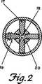
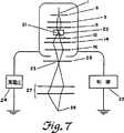
図1は、色消しイオンビームコラムの切断面を示す。図2は、インターリーブ四重極レンズの切断面を示す。図3〜図7は、光学系のこの2つの主要部分の典型的なイオン光線を示す色消しコラムの図である。図4〜図7では、インターリーブレンズ中で負の色収差がコラム中の他のレンズの色収差を補正するために使われている。図4では、集束レンズがイオンを平行ビームの収斂させる。図5では、集束レンズがイオンを交差させる。図6は質量分離色消しイオンビームコラムを示し、図7は2つのレンズコラムで使用できるエネルギよりもより高い質量分離エネルギの細く集束されたビームのための質量分離色消し装置を示す。
イオンビームコラムの液体金属イオン源1は、通常、付近の抽出電極8から数キロボルトの負の電位におかれ、抽出電極8は、典型的にイオンビームを通過させるように孔が穿設された平らな表面を有する。イオンおよび電子光学において周知のように、これは発散レンズとして働く「有孔電極レンズ」を形成する。ポート7に接続されたイオンポンプは、イオン源付近で10-8Torrの真空を作るために設けられている。
抽出電極の後段には、適正に調整されればイオンを平行ビームに収斂できる集束レンズ装置2がある。単一の集束レンズを使用することはできるが、イオンの抽出は狭い電圧の範囲でしかうまくいかず、また単一ギャップの焦点作用には一定の電圧を必要とするので、出力エネルギは実質的に固定される。それゆえに可変イオンエネルギの供給手段として2レンズ集束装置が有効である。電極8,9,10はこのような集束レンズ装置の1つを形成し、このうち3つの電極間のギャップ5,6は円形静電レンズを形成する。イオン源と電極とは従来の技術の周知の方法による高電圧電源で必要な電圧に保持されている。
集束レンズを出たイオンはドリフト空間3を通過し、インターリーブ四重極レンズ4に入る。ドリフト空間には、ビーム方向軸の周囲の任意の方位角に一平面内のビームを偏向することができる多重極ディフレクタ11,13が置かれてあり、独立した相互に干渉しない4枚の羽板(ベーン)から成るアパーチャを規定する組立体12がこの空間に置かれている。明確化のために、そのうちの1枚のみが図示されている。
図2に示されたように、インターリーブ四重極レンズは、ビーム方向に対して周囲に等方位角で等間隔に中心を置いた8つの極を有している。これらの極は交互に磁極17と電気極18とであり、それによって電気四重極レンズと磁気四重極レンズとを形成する。極の45度の角度間隔は、2つのレンズの四重極力場に一致する主断面を持たせる一方で、単一平面内にそれらの中心を位置させることは、レンズに一致する主平面を持たせる。
好ましい実施形態において、周囲に巻線19を有する強磁性材料から成る極17がセラミックスペーサ20に固く接着され、該スペーサは、また反磁性体電極18を支持するために用いる。このように、この構造は2つの相互に干渉しない入れ子式の四重極素子を形成し、これらの両方の四重極素子はほとんど完全な四重極場を達成するために必要な大きな極先端半径を有することができる。かご形構造はより小さな極先端を有し、四重極電圧で励起されるときに不要な多重極場を必然的に導入する。
インターリーブレンズは、電気力対磁気力の調整可能な比を有する単一の四重極力場を形成するために利用することができる。この力の比Rは、従来の技術の周知の方法に従って、電極電圧と巻線電流とを測定することと、磁場の強さと電場の強さとをこのような測定に関係づける数式とによって決定される。
R=−0.5になるように電気力が磁気力の大きさの半分に調整され方向が逆にされるとき、インターリーブレンズはEについて一次の色消しとなる。このことは、物点を、
d=C1 a dE/E+C2 a (dE/E)2
の形の主断面の幅を有するスポットに結像することを意味し、ここでC1=0である。
電気力はさらに増大するが、磁気力よりも大きくない場合、インターリーブレンズは負の値のC1を有する色収差補償レンズとなる(V.M.KelmanおよびS.Ya.Yavor, Zuhrnal Tekhnicheskoi Fiziki33(1963)368)。他の力の比においては、これは正の値のC1を有する通常のレンズとして働く。
両方の主断面で集束できる最も簡単なレンズ構成は、二重レンズ装置である。上流側のインターリーブレンズ14と下流側のインターリーブレンズ16とは、そのような二重レンズを構成する。スペーサ15は、これらのレンズの間隔の調整に役立つ。2つのレンズから成る装置は、その2つのレンズの中心で定められる1つの軸を必ず有し、適正に作動するためには、流入ビームに対して全体として二重レンズ装置の角度調整だけが必要となる。二重レンズはその2つの主断面で異なる倍率を有し、したがって2つの小さい異なる幅を持った集束されたビームを作る働きをする。
図3に示されたように、集束レンズのすべての電極が同一電圧に設定される場合、集束効果はなく、したがって色収差を起こさない。機能要素はイオン源1と抽出電極8と二重インターリーブ四重極レンズ装置4とから成る。インターリーブレンズが色消し作動点に設置されると、この光学コラムの最後の集束レンズによる色収差は導入されない。2つの装置が同じビーム幅で作動される場合には、イオン源、抽出電極および静電レンズから成る同様な寸法の装置よりも、本装置での焦点像はそれに相応して小さい。このビーム幅は調整可能なアパーチャで定められる。焦点像の大きさが同じであるとき、静電レンズを含むコラムよりも、インターリーブレンズを有するコラムはより大きいイオン電流を生成するように、この幅が増加できる。
図4に示されたように、集束レンズの電極が適正な電圧にされると、イオン源からより多くのイオンがインターリーブレンズ4内に導かれる。LMISからの大部分のイオン電流は半角約14度の範囲内で発生する。イオン源から最初のレンズギャップまでの間隔が9mmのとき、最初のレンズの直径が充分に大きければ幅約5mmの平行ビームが形成されるであろう。
拡大された角度asとbsとがおそらく原因して集束レンズの色収差を大きくする。正の色収差を除くために、二重インターリーブレンズはそれを正確に補償する負の色収差を作るように調整される。調整は、角度を規定するアパーチャ12を小さく調整してイオンエネルギEに対してスポットの大きさが敏感でなくなることによって決定される。このような調整は、加速電極の孔と、イオン源および抽出電極間のギャップにおける加速電場とで形成されたアパーチャレンズを含むすべての収差源から生じる正の一次の色収差を補償する。次いで、残りの高次の収差が集束されたビームを特定のスポット直径に至らせる位置まで、アパーチャが開けられてもよい。それによって、色収差を相殺するためのインターリーブ四重極レンズ装置を含まない装置と比べて、焦点像に入るイオン電流が増大する。
2つの独立した主断面を有するインターリーブレンズが円形レンズの色収差を補償するように調整できるということは直ちにわかることではない。単一のインターリーブレンズではそのようなことはできない。なぜならそれは2つの主断面に逆符号の収差を導入するからである。しかしながら、2つのインターリーブレンズは2つの変数を導入し、その系の寸法が与えられれば2つの主断面中の収差を表す連立線形方程式を解くことができる。図4の平行ビームの幾何学に対して、2つのインターリーブレンズの係数CxとCyとは、
Cx/Fx2=Cy/fy2=−C/h2
を満足させなければならない。ここでfxとfyとは二重レンズ4の焦点距離であり、hおよびCは円形レンズ2の焦点距離および色収差係数である。レンズを薄いとした近似計算では、二重レンズの上流側および下流側のレンズそれぞれの収斂断面における係数CyuおよびCxdとは、
Cyu/fu=−(1+2s/v)vC/2h2
Cxd/fd= −vC/2h2
で与えられる。ここでvは下流側レンズの像距離である。発散断面の係数は、
Cxu=−Cyu,Cxd=−Cyd
で与えられ、sはレンズ間距離である。ビームが平行でないときは別の式を適用する。薄いレンズ係数自体は、
Cyu/fu=(2Ru+1)/(2Ru+2)
Cxd/fd=(2Rd+1)/(2Rd+2)
でインターリーブレンズの寸法s,v、集束レンズのパラメータCおよびhが与えられれば、電気力対磁気力の比RuおよびRdが算出できるような形をとる。動作の最良の形態では、従来の技術に見られる型の電源が用いられ、該電源において、インターリーブレンズの電気部分および磁気部分が比例して変化し、固定値Rに対してfを変化させる。RuおよびRdは補償されるべきレンズのCおよびhのために計算された値に設定される。従来の技術において周知の手法によって、2つの四重極二重レンズのためのfuとfdとを変化させることによって集束されたビームを得る。
ディフレクタ11,13あるいはレンズ4の下流側のディフレクタを用いてミクロン以下のビームの大きさの測定をすることができる。集束されたビームがナイフエッジを横切るために必要な偏向からビームの幅が決定される。ラスタの線間距離がビーム幅よりも狭いとき、イオンビームスパッタリングによってナイフエッジの破壊を回避する方法は、ラスタ走査された薄い試料の部分でマイクロ機械加工するために必要な電荷を測定することである。ミクロン以下の試料を必要としない従来の技術の第3の方法は、dをaの関数として測定することである。1本のビーム束がアパーチャ12を小さくすることで生じたときは、ディフレクタ11,13の等しくかつ相対する設定は、イオン線がインターリーブレンズの軸から大きく外れてインターリーブレンズのアパーチャに入射され、したがってaの値を大きくさせる。インターリーブレンズが不適正に調整されたときは、大きくて簡単に測定可能な収差dが生じる。次いで、計算されたインターリーブレンズの磁気対電気比は、最小のスポットの大きさではなくてむしろ、最小の色収差を生じるように調整することができる。
2つの主断面内で倍率が等しくなるように、複数のインターリーブレンズから成る装置を設計することができる。そのような最も簡単な装置は、三重レンズである[L.R.Harriott,W.L.Browhn,D.L.Barr, J.Vac, Sci. Tech. B8(1990)1706]。三重レンズは作動が余計に複雑であり、3つのレンズの中心が確実に一直線上になるようにするためにかなりの高精度の機械加工を必要とするという短所がある。
このコラムは、平行ビームで作動させる必要はない。集束レンズは、一般的に、イオン源の中間像を形成し、この像はイオン源の上流側または最終焦像平面の下流側を含むコラムの任意の位置に存在する。このコラムは、このようにしていわゆるズームレンズを形成し、中間像の位置を変えると、像の最小の大きさが(色収差を考慮に入れずに倍率のみから決定されるように)変化する。図5に示されたように、集束レンズとその次のレンズとの間に中間像21が位置することがあり、この場合、この装置の軸をビームのまわりからのイオン線が交差するので、ビームは交差するといわれる。
液体合金型のイオン源は同時に数種類のイオンを生じ、1種類のイオンから成る集束されたビームを生じるためには質量分析が必要である。図6に示された集束レンズとその次の下流側レンズとの間に置かれたウィーン速度フィルタ22は、不要なイオン種をビームの方向軸から偏向し、そこで与えられた電荷対質量比を有するイオンのみが偏向されずに進めるようにする。このような偏向は任意の位置にある中間像に対して生じ、集束レンズから出る発散、平行、または収斂ビームを生成する。しかしながら、コラムの最良の作動は、フィルタによって導入された色収差が除去されるようにウィーンフィルタ22の中央で交差が生じるときに起こる。
インターリーブレンズのアパーチャを通過できないように充分に偏向されたイオンは、インターリーブレンズが結ぶ像から完全に除去される。このような装置は、ガリウム(質量69,71)などの所与の元素の質量が非常に近い同位元素を分離できないが、合金ベースイオン源によって作られた、質量差が大きく、異なる種類のイオンを分離するためには有用である。たとえば合金Ni4B6はNi2+(電荷対質量比30、収率32%)と商業上重要なB+1(電荷対質量比10または11、収率33%)とを生成する。静電集束レンズとインターリーブ四重極二重レンズとから成る装置は、マイクロ加工およびイオン注入などの目的のために1つの原子番号を有するイオンから最終像23を形成する際に有用である。
重いイオンと高エネルギとの組合せは、空冷式電磁石によって提供可能な磁場よりも大きな磁場を必要とするので、質量分析は一般的に近いEで行う必要がある。高エネルギで質量分析が行われる場合、ビームを大きい曲率半径で曲げる双極曲線磁石が必要である[マーチン、米国特許4,555,666号]。しかしながら、1ミクロンの数分の1の深さの部分をドープするために、半導体でのイオン注入は300kVまたはそれ以上のエネルギを要する。図7に示されたように、高電圧源24、制御エレクトロニクス25および加速ギャップ26はビームエネルギを増大させる働きをし、対物レンズ27はイオンを集束して高エネルギの最終像28を結ぶ。
2番目の中間像23が、図7に示されたように、加速ギャップに置かれると、そのギャップで導入される収差が最小化される。対物レンズ27は、円形静電レンズまたは円形磁気レンズ、電気、磁気またはインターリーブ四重極素子などを含むいずれの型のレンズでもよい。この複数のレンズにおける小さい角度a,bで最小のスポットの大きさを生じるように、インターリーブ四重極素子14,16のレンズ装置4の電気対磁気の比が調整され、それによってレンズ装置4の負の色収差を用いて、全ての他のイオン光学要素による正の色収差を補償する。色収差がそれによって最小にされたとき、角度設定アパーチャは高次の収差がスポットを大きくするまで開けられてもよい。イオン源1、集束レンズ2、インターリーブ四重極装置4、加速ギャップ26および対物レンズ27から成るコラムは、それによって、所与の大きさの最終焦像点における増加されたイオン電流を生じるように作用する。
最も有用な構成は、低エネルギでのインターリーブ四重極レンズ装置4を含むことである。なぜなら、電気力と磁気力とがこのようなレンズでは反対方向に向けられていることによって、さらに簡単なレンズと比べて同じ集束能力に達するために、より強い場を要するからである。この困難性は、インターリーブレンズが低エネルギの粒子で作動する、または小さい孔を有している場合には軽減される。対物レンズ27が磁気四重極二重レンズであり、その2番目のレンズ4が負の色収差を生じるように作動しているインターリーブレンズである場合、有用な装置が得られる。この装置では対物レンズ27は2番目のレンズ4によって導入された等しくない倍率の影響を弱めるために利用可能であり、それによって2つの主断面におけるこの装置の倍率を等しくできる。2番目のレンズ4が、大きな静電レンズであり、対物レンズ27が負の色収差を生じるように作動する小さい孔と短い焦点距離とを有するインターリーブ装置である場合、他の有用な装置が得られる。
これらの粒子ビームコラムの本質的特徴は、複数のインターリーブ四重極レンズを提供することであり、それらは総合すれば負の色収差を有し、コラム中の他の部品の正の色収差を補償するように作用する。
【図面の簡単な説明】
【図1】 色消しイオンビームコラムの切断面を示す。
【図2】 インターリーブ四重極レンズの切断面を示す。
【図3】 光学系の2つの主要部分の典型的なイオン光線を示す色消しコラムを示す図である。
【図4】 光学系の2つの主要部分の典型的なイオン光線を示す色消しコラムを示す図である。
【図5】 光学系の2つの主要部分の典型的なイオン光線を示す色消しコラムを示す図である。
【図6】 光学系の2つの主要部分の典型的なイオン光線を示す色消しコラムを示す図である。
【図7】 光学系の2つの主要部分の典型的なイオン光線を示す色消しコラムを示す図である。The US government owns a paid license for the present invention and, in limited circumstances, grants other rights to the patentee in reasonable terms under the terms of a grant granted by The National Science Foundation (ISI 85 21 280). Has the right to order to give a license.
TECHNICAL FIELD OF THE INVENTION The present invention is used in an apparatus for forming a finely focused ion beam, and generally includes ion implantation into semiconductors, material micromachining, ion beam lithography, and secondary ion microscopy. The present invention relates to the field of ion optics used in fields such as microfabrication and microanalysis.
Background of the Invention In the prior art, devices used to produce a narrow beam typically emit electrons, ionize the surrounding gas, or involve surface ionization at low temperatures, or most It typically consists of a source of acicular particles that are needles wet with a liquid metal or liquid alloy containing the desired ions. In some cases, a single lens is used to form an image of the minute emission portion of the particle source. Higher intensity can be obtained by using a focusing lens near the particle source or by using multiple focusing lenses. When several lenses are used, an intermediate image of the particle source can be formed. When the intermediate image is placed in the center of an ion optical element such as an acceleration gap or a Wien filter, the aberrations generated by that element are greatly reduced. However, the focusing ability of all systems utilizing electrostatic lenses is limited by the chromatic aberration of these lenses, coupled with the unavoidable diffusion of energy distribution of ions generated from the ion source. The total width d of the last focused image is
d = C a dE / E
Given as an expression of the form Where dE is the energy distribution around the median value of the ion energy E, a is the total convergence angle at the final focus, and C is the chromatic aberration coefficient. Chromatic aberration differs from other aberrations in that it is linearly dependent on a. For example, the spherical aberration of a circular lens changes as a3 . Therefore, the first order chromatic aberration is important in a small lens aperture in which the spherical aberration is very small, and the third order spherical aberration is dominant when the value of a is large.
Insufficient focusing ability of the electrostatic method is a cause of limiting the ability of the ion optical device which has been a difficult problem for a long time in the prior art. In applications such as micromachining, current density is the most important. The current from the liquid metal ion source is
I = B as bs r2
Given in. Typical values are brightness B = 106 A / sr-cm2 , radiation angles as , bs = 400 milliradians, effective ion source radius r, where r is less than 100 angstroms. Since the effective radius is very small, the beam size is not given by the ion source geometry, but rather by d. Therefore, the current density J is
J = I / d2 = B (as bs / ab) (rE / C dE)2
Given in. Since the quantity E / C is roughly constant for electrostatic lenses, it has been said that "the highest current density obtained of about 1 A / cm2 will not increase substantially in the near future." Even complex electrostatic lenses with four electrodes generate up to 10 A / cm2 . In order to overcome this long-standing problem, the object of the present invention is to increase the current density using an achromatic lens with C = 0.
Current is more important than current density when it is desired to cover a large sample area, such as ion implantation without a mask for the manufacture of application specific integrated circuits. At a current of 1 nA, the time to write on a 4 inch wafer with a dose of 1013 ions / cm2 in the single lens system is about 1 hour. At small currents, there are difficulties with such devices. Larger currents are obtained with devices having multiple lenses, so that larger values of a and b can be operated. However, such an enlarged angle introduces aberrations that would make the focused beam larger than the desired image size. At angles smaller than the intersection angle at which chromatic aberration and other aberrations are equal, removal of chromatic aberration will result in a larger working angle and a larger current for any given focused beam size. Accordingly, it is an object of the present invention to generate a high current by utilizing a complete achromatic scheme where C = 0 and to enable micromachining at higher writing speeds.
BRIEF DISCLOSURE OF THE INVENTION An ion beam column consisting of a liquid metal ion source and a plurality of electrostatic lenses cannot produce a narrow beam that is focused on a small point, similar to an ion source image. Instead, diffusion of the energy distribution of ions emitted from the ion source results in focal length variations that blur or enlarge the image. Such chromatic aberration is a property of the lens due to all static electricity and magnetism. The particle beam column excluding this problem is a combination of a needle ion source, a plurality of electrostatic lenses, and a plurality of interleaved quadrupole lenses. This interleaved quadrupole lens is an octupole lens in which electric poles and magnetic poles are alternately arranged to form an interleaved electromagnetic quadrupole lens. By adjusting the electrical-to-magnetic ratio, the interleaved lens can be achromatic, whereby the chromatic aberration of the column can be greatly reduced, or the chromatic aberration can be negative, thereby completely eliminating the chromatic aberration of the column.
Mass-separated ion beam columns, which eliminate unwanted ions produced by liquid alloy metal ion sources, are used in the field of ion implantation, but include a column with a Wien velocity filter placed after the ion source. Such a column need not be short and curved, but can produce a single atomic number of ions in the final focus.
The removal of chromatic aberration also allows the use of a larger aperture in the lens so that a higher beam current is generated at a given focused beam spot size. The size of the aperture is then limited by higher order aberrations rather than first order chromatic aberrations.
DESCRIPTION OF THE PREFERRED EMBODIMENTS FIG. 1 shows a cut surface of an achromatic ion beam column. FIG. 2 shows a cut surface of an interleaved quadrupole lens. FIGS. 3-7 are diagrams of achromatic columns showing typical ion rays of these two main parts of the optical system. 4-7, negative chromatic aberration is used in the interleaved lens to correct chromatic aberration of other lenses in the column. In FIG. 4, a focusing lens converges ions into a collimated beam. In FIG. 5, the focusing lens crosses the ions. FIG. 6 shows a mass separation achromatic ion beam column, and FIG. 7 shows a mass separation achromatic device for a finely focused beam with higher mass separation energy than can be used with two lens columns.
The liquid metal ion source 1 of the ion beam column is usually placed at a negative potential of several kilovolts from a
At the subsequent stage of the extraction electrode is a focusing
Ions exiting the focusing lens pass through the
As shown in FIG. 2, the interleaved quadrupole lens has eight poles centered at equal intervals at equal azimuth angles around the beam direction. These poles are alternately a
In a preferred embodiment, a
Interleaved lenses can be utilized to create a single quadrupole force field with an adjustable ratio of electrical force to magnetic force. This force ratio R is determined by measuring the electrode voltage and winding current according to well-known methods in the prior art and by the mathematical formula relating the strength of the magnetic field and the strength of the electric field to such a measurement. The
When the electrical force is adjusted to half the magnitude of the magnetic force so that R = −0.5 and the direction is reversed, the interleaved lens is first order achromatic for E. This means that
d = C1 a dE / E + C2 a (dE / E)2
Is imaged in a spot having the width of the main cross section of the form: C1 = 0.
If the electrical force is further increased, but not greater than the magnetic force, the interleaved lens becomes a chromatic aberration compensating lens having a negative value of C1 (VMKelman and S. Ya. Yavor, Zuhrnal Tekhnicheskoi Fiziki33 (1963) 368). In the ratio of the other forces, which acts as a normal lens with a C1 positive value.
The simplest lens configuration that can be focused on both main cross sections is a double lens arrangement. The
As shown in FIG. 3, when all the electrodes of the focusing lens are set to the same voltage, there is no focusing effect and therefore no chromatic aberration. The functional elements comprise an ion source 1, an
As shown in FIG. 4, when the electrodes of the focusing lens are set to an appropriate voltage, more ions are guided from the ion source into the
The enlarged angles as and bs probably increase the chromatic aberration of the focusing lens. In order to eliminate positive chromatic aberration, the double interleaved lens is adjusted to produce negative chromatic aberration that accurately compensates for it. Adjustment is determined by making the
It is not immediately apparent that an interleaved lens having two independent main cross sections can be adjusted to compensate for the chromatic aberration of a circular lens. That's not possible with a single interleaved lens. This is because it introduces aberrations of opposite signs in the two main cross sections. However, the two interleaved lenses introduce two variables and can solve the simultaneous linear equations representing the aberrations in the two main sections given the dimensions of the system. For the parallel beam geometry of FIG. 4, the coefficients Cx and Cy of the two interleaved lenses are
C x / F x 2 = C y /
Must be satisfied. Here, the fx and fy is the focal length of the
Cyu /fu = − (1 + 2 s / v) vC / 2h2
Cxd / fd = −vC / 2h2
Given in. Here, v is the image distance of the downstream lens. The coefficient of the divergence section is
Cxu = −Cyu , Cxd = −Cyd
S is the distance between lenses. If the beams are not parallel, another formula applies. The thin lens coefficient itself is
Cyu /fu = (2Ru +1) / (2Ru +2)
Cxd / fd = (2Rd +1) / (2Rd +2)
If the dimensions s and v of the interleave lens and the parameters C and h of the focusing lens are given, the ratios Ru and Rd of the electric force to magnetic force can be calculated. In the best mode of operation, a power supply of the type found in the prior art is used, in which the electrical and magnetic parts of the interleaved lens change proportionally and vary f with respect to a fixed value R. Ru and Rd are set to the values calculated for C and h of the lens to be compensated. A focused beam is obtained by varying fu and fd for the two quadrupole double lenses by techniques well known in the prior art.
The size of the submicron beam can be measured using the
A device consisting of a plurality of interleaved lenses can be designed such that the magnification is equal in the two main cross sections. The simplest such device is a triple lens [LR Harriott, WLBrowhn, DLBarr, J. Vac, Sci. Tech. B8 (1990) 1706]. The triple lens is more complicated to operate and has the disadvantage of requiring significant precision machining to ensure that the centers of the three lenses are in line.
This column need not be operated with a parallel beam. The focusing lens generally forms an intermediate image of the ion source, which is present at any position in the column including upstream of the ion source or downstream of the final focal plane. This column forms a so-called zoom lens in this way, and changing the position of the intermediate image changes the minimum size of the image (as determined from magnification alone without taking chromatic aberrations into account). As shown in FIG. 5, an
Liquid alloy type ion sources produce several types of ions at the same time and require mass spectrometry to produce a focused beam of one type of ion. A
Ions that are sufficiently deflected so that they cannot pass through the aperture of the interleave lens are completely removed from the image formed by the interleave lens. Such an apparatus cannot separate isotopes that are very close in mass for a given element, such as gallium (mass 69, 71), but with a large mass difference and different types of ions produced by alloy-based ion sources. It is useful for isolating. For example, the alloy Ni4 B6 produces Ni2+ (charge to mass ratio 30, yield 32%) and commercially important B+1 (charge to
Since the combination of heavy ions and high energy requires a larger magnetic field than can be provided by an air-cooled electromagnet, mass spectrometry generally needs to be performed at a near E. When mass analysis is performed at high energy, a bipolar curvilinear magnet that bends the beam with a large radius of curvature is required [Martin, US Pat. No. 4,555,666]. However, in order to dope a fraction of a micron in depth, ion implantation in a semiconductor requires 300 kV or more energy. As shown in FIG. 7,
When the second
The most useful configuration is to include a low energy interleaved
The essential feature of these particle beam columns is to provide a plurality of interleaved quadrupole lenses, which together have negative chromatic aberration and compensate for positive chromatic aberration of other components in the column. Acts as follows.
[Brief description of the drawings]
FIG. 1 shows a cut surface of an achromatic ion beam column.
FIG. 2 shows a cut surface of an interleaved quadrupole lens.
FIG. 3 shows an achromatic column showing typical ion rays of the two main parts of the optical system.
FIG. 4 shows an achromatic column showing typical ion rays of the two main parts of the optical system.
FIG. 5 shows an achromatic column showing typical ion rays of the two main parts of the optical system.
FIG. 6 shows an achromatic column showing typical ion rays of the two main parts of the optical system.
FIG. 7 shows an achromatic column showing typical ion rays of the two main parts of the optical system.
Claims (7)
Translated fromJapanese針状粒子源と、
複数のレンズと、
複数のインターリーブ四重極レンズであって、各インターリーブ四重極レンズが電気極と磁気極とが交互に配置された8極レンズである、複数のインターリーブ四重極レンズとを含み、
前記各インターリーブ四重極レンズは、インターリーブ四重極レンズの負の色収差が他の全ての粒子光学要素の正の色収差を正確に相殺し、像点直径が粒子エネルギの小さな変化とは実質的に無関係であるような電場対磁場の臨界比において使用されることを特徴とする粒子光学コラム。A particle optic column for forming a finely focused particle beam comprising:
A source of acicular particles;
Multiple lenses,
A plurality of interleaved quadrupole lenses, each interleaved quadrupole lens being an 8-pole lens in which electrical and magnetic poles are alternately arranged, and a plurality of interleaved quadrupole lenses,
In each of the interleaved quadrupole lenses, the negative chromatic aberration of the interleaved quadrupole lens accurately cancels the positive chromatic aberration of all other particle optical elements, and the image point diameter is substantially different from a small change in particle energy. Particle optical column, characterized in that it is used at a critical ratio of electric field to magnetic field that is unrelated.
抽出電極と、
集束レンズと、
細く集束された粒子ビームを形成するための二重インターリーブ四重極レンズであって、各インターリーブ四重極レンズが電気極と磁気極とが交互に配置された8極レンズである、二重インターリーブ四重極レンズとを含む粒子光学コラムであって、
前記インターリーブ四重極レンズは、針状粒子源と抽出電極とによって生成される正の色収差にいかなる色収差も加えず、像点直径のエネルギ依存が、静電レンズだけを用いて細いビームを形成するコラムと比べて低減されるような電場対磁場の臨界比において使用されることを特徴とする粒子光学コラム。A source of acicular particles;
An extraction electrode;
A focusing lens;
A double interleaved quadrupole lens for forming a finely focused particle beam, wherein each interleaved quadrupole lens is an octupole lens with alternating electrical and magnetic poles A particle optical column including a quadrupole lens,
The interleaved quadrupole lens does not add any chromatic aberration to the positive chromatic aberration generated by the acicular particle source and the extraction electrode, and the energy dependence of the image point diameter forms a thin beam using only the electrostatic lens. A particle optical column, characterized in that it is used in a critical ratio of electric field to magnetic field that is reduced compared to the column.
該粒子光学コラムが、針状粒子源と、複数のインターリーブ四重極レンズを含む他のレンズであって、各インターリーブ四重極レンズが電気極と磁気極とが交互に配置された8極レンズである、他のレンズとを含み、
前記複数のインターリーブ四重極レンズの各インターリーブ四重極レンズは、インターリーブ四重極レンズの負の色収差が他の全ての粒子光学要素の正の色収差を両主断面において同時に正確に相殺し、像点直径が粒子エネルギの小さな変化とは実質的に無関係であるような電場対磁場の臨界比において使用されることを特徴とする請求項1記載の粒子光学コラムを使用する方法。A method for using a particle optic column to form a finely focused particle beam comprising:
The particle optical column is another lens including an acicular particle source and a plurality of interleaved quadrupole lenses, and each interleaved quadrupole lens has an electric pole and a magnetic pole alternately arranged. Including other lenses,
Each of the interleaved quadrupole lenses of the plurality of interleaved quadrupole lenses is configured such that the negative chromatic aberration of the interleaved quadrupole lens accurately cancels the positive chromatic aberration of all other particle optical elements simultaneously in both main cross sections, thereby 2. A method of using a particle optic column according to claim 1 wherein the point diameter is used in a critical ratio of electric field to magnetic field which is substantially independent of small changes in particle energy.
該粒子光学コラムが、針状粒子源と、抽出電極を含む集束レンズ装置と、二重インターリーブ四重極レンズから成るレンズ装置であって、各インターリーブ四重極レンズが電気極と磁気極とが交互に配置された8極レンズである、レンズ装置とを含み、
前記二重インターリーブ四重極レンズの各インターリーブ四重極レンズは、針状粒子源と抽出電極とによって生成される正の色収差にいかなる色収差も加えず、像点直径のエネルギ依存が、静電レンズだけを用いて細いビームを形成するコラムと比べて低減されるような電場対磁場の臨界比において使用されることを特徴とする粒子光学コラムを使用する方法。A method of using a particle optical column to form a finely focused particle beam comprising:
The particle optical column is a lens device comprising a needle-like particle source, a focusing lens device including an extraction electrode, and a double interleaved quadrupole lens, each interleaved quadrupole lens having an electric pole and a magnetic pole. A lens device, which is an alternately arranged octupole lens,
Each interleaved quadrupole lens of the double interleaved quadrupole lens does not add any chromatic aberration to the positive chromatic aberration generated by the acicular particle source and the extraction electrode, and the energy dependence of the image point diameter is an electrostatic lens. A method of using a particle optic column, characterized in that it is used at a critical ratio of electric field to magnetic field that is reduced compared to a column that uses only a thin beam to form.
Applications Claiming Priority (1)
| Application Number | Priority Date | Filing Date | Title |
|---|---|---|---|
| PCT/US1994/013358WO1996016426A1 (en) | 1993-08-20 | 1994-11-18 | Chromatically compensated particle-beam column |
Publications (2)
| Publication Number | Publication Date |
|---|---|
| JPH10506225A JPH10506225A (en) | 1998-06-16 |
| JP3844253B2true JP3844253B2 (en) | 2006-11-08 |
Family
ID=22243299
Family Applications (1)
| Application Number | Title | Priority Date | Filing Date |
|---|---|---|---|
| JP51678996AExpired - Fee RelatedJP3844253B2 (en) | 1994-11-18 | 1994-11-18 | Particle beam chromatic aberration compensation column |
Country Status (8)
| Country | Link |
|---|---|
| EP (1) | EP0745266B1 (en) |
| JP (1) | JP3844253B2 (en) |
| KR (1) | KR100308720B1 (en) |
| AU (1) | AU689528B2 (en) |
| CA (1) | CA2188997C (en) |
| DE (1) | DE69432670T2 (en) |
| RU (1) | RU2144237C1 (en) |
| WO (1) | WO1996016426A1 (en) |
Families Citing this family (4)
| Publication number | Priority date | Publication date | Assignee | Title |
|---|---|---|---|---|
| EP0883891B1 (en)* | 1996-12-03 | 2003-04-23 | Fei Company | Method of operating a particle-optical apparatus |
| US6593578B1 (en)* | 2001-11-08 | 2003-07-15 | Schlumberger Technologies, Inc. | Wien filter for use in a scanning electron microscope or the like |
| EP1956630A1 (en) | 2007-02-06 | 2008-08-13 | ICT Integrated Circuit Testing Gesellschaft für Halbleiterprüftechnik mbH | Achromatic mass separator |
| WO2013120097A1 (en)* | 2012-02-09 | 2013-08-15 | Fluxion Inc. | Compact, filtered ion source |
Family Cites Families (5)
| Publication number | Priority date | Publication date | Assignee | Title |
|---|---|---|---|---|
| US4555666A (en)* | 1979-03-29 | 1985-11-26 | Martin Frederick W | Energy-stable accelerator with needle-like source and focused particle beam |
| US4590379A (en)* | 1980-09-16 | 1986-05-20 | Martin Frederick W | Achromatic deflector and quadrupole lens |
| EP0175933A1 (en)* | 1984-09-21 | 1986-04-02 | Siemens Aktiengesellschaft | Scanning lens system without deflection chromatic defects for corpuscular beam treatment of material |
| RU2017255C1 (en)* | 1990-12-26 | 1994-07-30 | Алексей Владимирович Аленичев | Method of initiation of emission of charged particles and control over it |
| RU2067784C1 (en)* | 1994-05-27 | 1996-10-10 | Евгений Денисович Донец | Ion source |
- 1994
- 1994-11-18CACA002188997Apatent/CA2188997C/ennot_activeExpired - Lifetime
- 1994-11-18JPJP51678996Apatent/JP3844253B2/ennot_activeExpired - Fee Related
- 1994-11-18EPEP95904093Apatent/EP0745266B1/ennot_activeExpired - Lifetime
- 1994-11-18RURU96116893Apatent/RU2144237C1/ennot_activeIP Right Cessation
- 1994-11-18DEDE69432670Tpatent/DE69432670T2/ennot_activeExpired - Lifetime
- 1994-11-18AUAU13706/95Apatent/AU689528B2/ennot_activeCeased
- 1994-11-18WOPCT/US1994/013358patent/WO1996016426A1/enactiveIP Right Grant
- 1994-11-18KRKR1019960703883Apatent/KR100308720B1/ennot_activeExpired - Fee Related
Also Published As
| Publication number | Publication date |
|---|---|
| KR100308720B1 (en) | 2001-12-15 |
| DE69432670T2 (en) | 2004-03-11 |
| AU1370695A (en) | 1996-06-17 |
| CA2188997C (en) | 2002-08-06 |
| KR970700926A (en) | 1997-02-12 |
| RU2144237C1 (en) | 2000-01-10 |
| DE69432670D1 (en) | 2003-06-18 |
| EP0745266B1 (en) | 2003-05-14 |
| JPH10506225A (en) | 1998-06-16 |
| AU689528B2 (en) | 1998-04-02 |
| WO1996016426A1 (en) | 1996-05-30 |
| CA2188997A1 (en) | 1996-05-30 |
| EP0745266A1 (en) | 1996-12-04 |
| EP0745266A4 (en) | 1998-01-28 |
Similar Documents
| Publication | Publication Date | Title |
|---|---|---|
| CN102468104B (en) | With the charged particle source of integrated static energy filter | |
| CN102064074B (en) | For the adjuster of the axial aberration of particle-optical lens | |
| US7875858B2 (en) | Charged particle beam trajectory corrector and charged particle beam apparatus | |
| CN112233960A (en) | Charged Particle Beam Device | |
| JP4881661B2 (en) | Charged particle beam equipment | |
| US20090184243A1 (en) | Charged particle beam apparatus | |
| US5369279A (en) | Chromatically compensated particle-beam column | |
| EP2478546B1 (en) | Distributed ion source acceleration column | |
| JP2012227141A (en) | Wien e×b mass filter of aberration correction for removing neutral material from beam | |
| US20240170248A1 (en) | Particle beam system | |
| JP2000500913A (en) | Correction device for correcting chromatic aberration of particle optics | |
| JP2020074329A (en) | Electron beam imaging device and method | |
| US20040084621A1 (en) | Beam guiding arrangement, imaging method, electron microscopy system and electron lithography system | |
| JPH02229418A (en) | Condensed ion beam column | |
| JP4823995B2 (en) | Aberration correction type mass separator | |
| JP3844253B2 (en) | Particle beam chromatic aberration compensation column | |
| JPH01319236A (en) | Field emission electron gun | |
| JPS62108438A (en) | High current mass spectrometer employing space charge lens | |
| JP4343951B2 (en) | Single stage charged particle beam energy width reduction system for charged particle beam system | |
| JP4023556B2 (en) | Electro-optic lens device having a gap-shaped aperture cross section | |
| JP2024023157A (en) | Simple spherical aberration corrector for SEM | |
| JP5204277B2 (en) | Charged particle beam equipment | |
| CN1142280A (en) | Particle Beam Columns for Chromatic Aberration Compensation | |
| Jamieson et al. | Beam optics on the Melbourne proton microprobe | |
| JPS6313250A (en) | Ion beam device |
Legal Events
| Date | Code | Title | Description |
|---|---|---|---|
| A131 | Notification of reasons for refusal | Free format text:JAPANESE INTERMEDIATE CODE: A131 Effective date:20040914 | |
| A601 | Written request for extension of time | Free format text:JAPANESE INTERMEDIATE CODE: A601 Effective date:20041214 | |
| A602 | Written permission of extension of time | Free format text:JAPANESE INTERMEDIATE CODE: A602 Effective date:20050207 | |
| A521 | Request for written amendment filed | Free format text:JAPANESE INTERMEDIATE CODE: A523 Effective date:20050314 | |
| TRDD | Decision of grant or rejection written | ||
| A01 | Written decision to grant a patent or to grant a registration (utility model) | Free format text:JAPANESE INTERMEDIATE CODE: A01 Effective date:20060725 | |
| A61 | First payment of annual fees (during grant procedure) | Free format text:JAPANESE INTERMEDIATE CODE: A61 Effective date:20060811 | |
| R150 | Certificate of patent or registration of utility model | Free format text:JAPANESE INTERMEDIATE CODE: R150 | |
| FPAY | Renewal fee payment (event date is renewal date of database) | Free format text:PAYMENT UNTIL: 20100825 Year of fee payment:4 | |
| FPAY | Renewal fee payment (event date is renewal date of database) | Free format text:PAYMENT UNTIL: 20100825 Year of fee payment:4 | |
| FPAY | Renewal fee payment (event date is renewal date of database) | Free format text:PAYMENT UNTIL: 20110825 Year of fee payment:5 | |
| FPAY | Renewal fee payment (event date is renewal date of database) | Free format text:PAYMENT UNTIL: 20120825 Year of fee payment:6 | |
| LAPS | Cancellation because of no payment of annual fees |