JP3843578B2 - Diagnostic equipment for vehicles - Google Patents
Diagnostic equipment for vehiclesDownload PDFInfo
- Publication number
- JP3843578B2 JP3843578B2JP02486998AJP2486998AJP3843578B2JP 3843578 B2JP3843578 B2JP 3843578B2JP 02486998 AJP02486998 AJP 02486998AJP 2486998 AJP2486998 AJP 2486998AJP 3843578 B2JP3843578 B2JP 3843578B2
- Authority
- JP
- Japan
- Prior art keywords
- vehicle
- output
- control unit
- communication unit
- diagnosis result
- Prior art date
- Legal status (The legal status is an assumption and is not a legal conclusion. Google has not performed a legal analysis and makes no representation as to the accuracy of the status listed.)
- Expired - Fee Related
Links
- 238000003745diagnosisMethods0.000claimsdescription87
- 238000004891communicationMethods0.000claimsdescription78
- 230000005856abnormalityEffects0.000claimsdescription58
- 230000005540biological transmissionEffects0.000claimsdescription52
- 230000004044responseEffects0.000claimsdescription36
- 230000007704transitionEffects0.000claims2
- 238000000034methodMethods0.000description81
- 230000008569processEffects0.000description77
- 238000010586diagramMethods0.000description9
- 230000002159abnormal effectEffects0.000description8
- 230000001186cumulative effectEffects0.000description5
- 238000007689inspectionMethods0.000description5
- 238000012423maintenanceMethods0.000description4
- 238000004092self-diagnosisMethods0.000description4
- 239000007858starting materialSubstances0.000description4
- XLYOFNOQVPJJNP-UHFFFAOYSA-NwaterSubstancesOXLYOFNOQVPJJNP-UHFFFAOYSA-N0.000description4
- 230000008859changeEffects0.000description3
- 238000007726management methodMethods0.000description3
- 230000008439repair processEffects0.000description3
- 238000004458analytical methodMethods0.000description2
- 238000004364calculation methodMethods0.000description2
- 238000013500data storageMethods0.000description2
- 230000003111delayed effectEffects0.000description2
- 230000000694effectsEffects0.000description2
- 239000000446fuelSubstances0.000description2
- 238000002347injectionMethods0.000description2
- 239000007924injectionSubstances0.000description2
- 230000008901benefitEffects0.000description1
- 239000003054catalystSubstances0.000description1
- 230000006378damageEffects0.000description1
- 230000007547defectEffects0.000description1
- 230000002950deficientEffects0.000description1
- 238000001514detection methodMethods0.000description1
- 230000006872improvementEffects0.000description1
Images


Landscapes
- Combined Controls Of Internal Combustion Engines (AREA)
Description
Translated fromJapanese【0001】
【発明の属する技術分野】
本発明は、車両に搭載された各種機器の状態を診断する車両用診断装置であって、特に、その診断結果を外部の管理センタ側へ送信可能にされた車両用診断装置に関する。
【0002】
【従来の技術】
車両のメインテナンスは、例えば、日本では一定期間ごとの車検に応じてユーザーが整備工場にて検査及び修理をしてもらい陸運局に報告するようにしており、また米国では監督局からの定期的な通知に従いユーザーが整備工場で検査及び修理を受け基準を満たしていることを監督局に返信するというようにして管理されている。
【0003】
ところがこのような方式では、特に故障や不良が無く整備の必要の無い車両まで一律に管理しているため、監督局(陸運局)での管理の工数が多くなっていると共に、ユーザにとっても煩わしいものである。
このようなことから、車両側にて検査に関わる情報(例えば、エンジン関連部品の異常に関する情報)を車両から無線通信にて監督局側としての管理センタ側に送信し、特に修理が必要な車両に対してそのユーザーに指示し報告させるようにすることが考えられる。
【0004】
【発明が解決しようとする課題】
このようなシステムとした場合、車両側では無線通信を送受信するための装置(以下、トランスポンダという)を装備すると共に、検査に関わる情報を車載の制御ユニットで得て、制御ユニットからトランスポンダに通信するよう構成する必要が生じる。
【0005】
しかしながら、管理センタ側から車両に対して、検査に関わる情報の送信要求が出され、その送信要求を受けたトランスポンダが検査に関わる情報を管理センタ側に送信するというような、車両側が受動的なシステムとした場合には、次のような不都合が生じる。つまり、管理センタ側からの送信要求はいつ送られてくるか判らないため、要求がいつ来ても応答できるように車両側にシステムを構築しておく必要がある。このためには、例えば車載のトランスポンダや制御ユニットを常時オン状態にしておけばよいが、一般的にエンジン停止状態では車載バッテリに対して充電がされないため、上記「常時オン」しておく方法では、トランスポンダや制御ユニットによって消費される電力によって短期間でバッテリが消耗してしまうこととなる。
【0006】
そこで、本発明は、管理センタ側からの送信要求がいつ来ても応答できるように構成されていながら、バッテリ消耗を極力少なくした車両用診断装置を提供することを目的とする。
【0007】
【課題を解決するための手段及び発明の効果】
上記目的を達成するためになされた請求項1記載の車両用診断装置によれば、車両に搭載されたエンジンを制御する制御ユニットがエンジンのエミッションに関連する異常を診断し、その診断結果は、当該制御ユニットと同じく前記車両に搭載され、制御ユニットと通信ラインで接続された通信ユニットによって外部の管理センタ側へ送信される。これら制御ユニット及び通信ユニットは、車載エンジンの駆動によって充電されるバッテリから供給された電力によって動作するが、バッテリから通信ユニットへは通常動作に必要な電力が常時供給されるよう構成されているため、通信ユニットは、管理センタ側からの送信要求がいつ来ても、それに応じて診断結果を管理センタ側に送信することができる。
【0008】
一方、バッテリから制御ユニットへは通常動作に必要な電力が供給される状態と供給されない状態とが切り替え可能に構成されており、供給状態設定手段は、車両の使用中は、バッテリから制御ユニットへ通常動作に必要な電力が供給される状態に設定し、一方、車両の不使用中は、バッテリから制御ユニットへ通常動作に必要な電力が供給されない状態に切替設定する。したがって、車両が不使用中で車載エンジンが停止しておりバッテリが充電されない状況では制御ユニットへの電力供給が低減(停止も含む)されるため、その分のバッテリ消耗が少なくなる。
【0009】
つまり、いつ来るか判らない管理センタ側からの送信要求に対して、いつ来てもそれに応答できるようにするため、通信ユニットに加えて制御ユニットまでも通常動作できるように準備しておくのはバッテリ消耗の点からすれば非合理的である。そこで、上記送信要求に応答するためだけであれば最低限通信ユニットだけ動作できればよいので、制御ユニット側への通常動作可能な電力の供給はしないようにする。
【0010】
但し、車両が不使用中は制御ユニットへ通常動作可能な電力が供給されないため、その車両不使用中に管理センタ側から送信要求があった場合には、その時点で制御ユニットから診断結果を取得することはできない。したがって、制御ユニットは通常動作に必要な電力が供給される状態にあるときに通信ユニットに診断結果を送信するようになっており、通信ユニットは、その時点で制御ユニットから診断結果を取得する代わりに、車両が不使用状態になる以前の車両使用中、具体的には制御ユニットが通常動作に必要な電力が供給されているときに制御ユニットから得ていた最新の診断結果を送信する。
【0011】
これによって、管理センタ側からの送信要求がいつ来ても応答できるように構成されていながら、バッテリ消耗を極力少なくした車両用診断装置を提供することができる。
なお、「通常動作に必要な電力が供給されない状態」としたのは、次の理由からである。例えばマイクロコンピュータにおけるRAM内のデータを車両不使用状態でも保持しておくためには、やはり電力供給はされる必要がある。しかし、これは例えば制御ユニットとしてのエンジンECUを考えると、通常のエンジン制御を実行したりするのに必要な電力までは不要である。したがって、もちろんこのようなRAM内のデータを保持したりする必要がなければ、電力供給を完全に停止してもよいが、上述の事情も含め、「通常動作に必要な電力が供給されない状態」としたのである。
【0012】
また、車両の状態として「使用中」と「不使用中」と表現したのは次の理由からである。つまり、エンジンが駆動していれば必ず使用中ではあるが、例えばエンジンが駆動していなくても、車載機器のカーナビゲーションシステム等を使用することもできる。このカーナビゲーションシステムは一般的な自動車においてはアクセサリスイッチがオンされていれば使用できる。したがって、ここではそれらも含める意味で使用中・不使用中という語を用いた。具体的には、一般的な自動車においては、OFF・ACC・ON・STARTの4位置を持つキースイッチが多いので、この場合にはOFFだけが「不使用中」であり、残りのACC・ON・STARTの場合は全て「使用中」と考えることができる。つまり、車両の利用者が、バッテリにて動作する車載装備を使用する場合が使用中である。したがって、キースイッチがOFFの状態にて何らかの車載装備を使用したとしても、それは使用中ではなく「不使用中」である。
【0013】
なお、上述した車両不使用中に通信ユニットが送信する「最新の診断結果」については、例えば、請求項2に示すように、車両使用中は、制御ユニットが自発的に、あるいは通信ユニットからの出力要求に応じて通信ユニットへ診断結果を出力するようにし、その車両使用中に最後に出力された診断結果を「最新の診断結果」としてもよい。この場合、例えば、制御ユニットから定期的に診断結果を出力し、通信ユニットではそれを更新記憶しておくようにすれば、通信ユニットに記憶されたものがそのまま「最新の診断結果」になる。
【0014】
あるいは、請求項3に示すように、供給状態設定手段によって、車両が使用状態から不使用状態に移行した場合、その移行時点から所定期間は制御ユニットの通常動作に必要な電力が供給されている状態を継続することで、その所定期間中に制御ユニットから診断結果を出力させ、その所定期間中に出力された診断結果を「最新の診断結果」としてもよい。この場合には、「最新の診断結果」としてより適切なものが得られるため、適切な診断のためには好ましい。つまり、制御ユニットから定期的に出力される診断結果の内の最後のものを「最新の診断結果」とする場合、出力間隔によっては、車両が使用状態から不使用状態に切り替わる直前の状態を反映した診断結果とはならない可能性もある。例えば、最後の診断結果を出力した後でも車両が走行している場合もあり、その走行によって異常が発生する可能性もある。請求項3に示すようにすれば、このような不都合は解消される。
【0015】
ところで、制御ユニットから通信ユニットへ出力される診断結果は、基本的には車両使用中に出力されるものである。そのため、例えば診断結果の出力タイミングがエンジン始動時に重なると、通信状態が悪い状態なので通信ユニットと制御ユニットとの間の通信ライン上にノイズが乗り、例えば通信ユニットに入力された信号が制御ユニットから出力された信号と異なってしまう可能性がある。その場合には、誤った情報が管理センタ側に送られてしまう。また、制御ユニットのマイクロコンピュータ(以下「マイコン」と略記する)が忙しい時、例えばエンジン制御ユニットであれば、エンジン高回転時や高負荷時などにおいては、通信ユニットへの出力データ量が多くなると、本来の制御処理に影響を与える可能性がある。
【0016】
したがって、上述したバッテリ消耗の低減等の効果を得ながら、さらにこのような不都合を防止するためには、上述した車両用診断装置の制御ユニットが、診断結果を通信ユニットに出力するには不適切な期間を判別し、その期間中は出力しないようにすることが好ましい。
【0017】
具体的には、制御ユニットが、エンジン始動に起因して通信ライン上にノイズが発生していると考えられる第1の不適期間中と、各種機器への制御に要する処理負荷が所定以上大きいと考えられる第2の不適期間中との少なくとも一方を判断し、前記不適期間と判断したときは、所定の通信ユニットへの出力タイミングであっても、診断結果を出力しないようにする。一方、不適期間に該当しない場合には、所定の出力タイミングにおいて診断結果を通信ユニットに出力する。
【0018】
上述した第1の不適期間中は、エンジン始動に起因し、例えばスタータを回転駆動させていることなどよって通信ライン上にノイズが発生している可能性が高い。そのため、この状態で制御ユニットから通信ユニットに診断結果が出力されると、それらユニット間の通信ライン上でデータ化けやデータ破壊が起こり、制御ユニットから出力されたのとは違う誤った診断結果が管理センタに送信されてしまう可能性がある。したがって、このような不適期間中に所定の出力タイミングが来ても診断結果は出力しない。
【0019】
また、上述した第2の不適期間中は、各種機器への制御に要する処理負荷が所定以上大きい期間である。各種機器への制御は制御ユニットの本来の仕事であり、優先度は相対的に高く、一方、診断結果の出力は相対的に見れば優先度が低い。つまり、制御ユニットが優先度の高い処理を実行するのに忙しい(つまりマイコンの処理負荷が高い)期間中においては、その優先度の高い処理を抑えてまで、あえて診断結果の出力という優先度の低い処理を実行する必要性はない。したがって、このような期間中に所定の出力タイミングが来ても診断結果は出力しない。なお、処理負荷が大きい状態とは、具体的には制御対象がエンジンであれば、そのエンジン回転数が高い状態などである。つまり、回転数に対応した処理タイミングを設定すると、エンジン高回転状態においては単位時間当たりの処理量が多くなるからである。特にエンジンについてはリアルタイム処理が必要であり、診断結果の出力のように、緊急性が低い処理については後回しで一向に構わないのである。
【0020】
ところで、「所定の出力タイミング」は、例えば通信ユニットからの出力要求を受けた制御ユニットが診断結果を出力するのであれば、その通信ユニットからの出力要求タイミングに基づくこととなる。そして、この方法であれば、管理センタ側からの送信要求に応じ、通信ユニットが制御ユニットに対して診断結果を出力するよう要求することが考えられる。このようにすれば、管理センタにおける管理に都合が良いタイミングで送信要求を出すことができるため、管理上の利点がある。
【0021】
そして、このように、管理センタ側からの送信要求に応じ、通信ユニットが制御ユニットに対して診断結果を出力するよう要求する場合には、制御ユニットが次のように対応することも考えられる。つまり、不適期間中において診断結果の出力要求があった場合には、その要求には対応しないが、要求があったこと自体は記憶しておき、その後、不適期間に該当しない状況となった時点で、記憶されている診断結果の出力要求に応じて、診断結果を通信ユニットに出力するのである。このようにすれば出力要求へのレスポンスは向上する。なぜなら、出力要求が来た時点で不適期間中であるかどうかを判断し、不適期間中であれば対応せず、不適期間中でなければ対応するだけの場合には、不適期間が過ぎていても、その後に出力要求が来るタイミングを待たなくてはならない。つまり、必ずしも不適期間が過ぎた直後に出力要求が来るとは限らないからである。それに対して、診断結果の出力要求があったこと自体は記憶しておき、その後、不適期間に該当しない状況となった時点で出力要求に応じるようにすれば、対応して良い状態になったら即座に応じることができるため、出力要求へのレスポンスは向上する。
【0022】
そして、このように、制御ユニットが、通信ユニットからの出力要求に応じて通信ユニットへ診断結果を出力することを前提とした場合には、通信ユニットが、制御ユニットから診断結果が複数回出力され、かつ複数回の診断結果の内容が一致するまで、繰り返し制御ユニットへ出力要求し、診断結果が一致すると、その一致した診断結果を管理センタ側へ送信するよう構成することが考えられる。制御ユニットから通信ユニットに出力された診断結果の正確性向上を期すためには、有効である。
【0023】
また、通信ユニットに異常がある場合の制御ユニット側の対処としては、次のようにすることも有効である。つまり、通信ユニットからの要求に応じて診断結果を所定回数以上出力したにもかかわらず、さらに診断結果の出力要求が来た場合には、それ以降の要求には対応しないようにするのである。
【0024】
なお、車両用診断装置は最終的には通信ユニットが管理センタ側に車両の診断結果を送信することとなるが、その診断結果に、車両固有の識別情報を含めることも考えられる。これは、診断結果がどの車両に対応するものなのかを容易に判別できる点で有効である。もちろん、これ以外にも、診断結果を送信してきた車両を特定する方法は考えられるが、診断結果に含まれていれば、特定が容易にできる。
【0025】
また、診断結果には、診断対象の機器に関する情報だけでなく、付帯情報として、例えば診断時における車両の走行距離あるいは車両位置の少なくとも一方を含めることも有効である。つまり、その診断対象の機器が搭載された車両自体の走行距離に応じても診断結果の分析は変わる可能性があるからである。また、車両位置についても同様である。
【0026】
以上説明した車両用診断装置においては、車載の様々な機器について、制御ユニットの制御対象とできる。
【0027】
【発明の実施の形態】
以下、本発明が適用された実施例について図面を用いて説明する。なお、本発明の実施の形態は、下記の実施例に何ら限定されることなく、本発明の技術的範囲に属する限り、種々の形態を採り得ることは言うまでもない。
【0028】
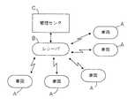
図1は、実施例の車両用診断装置の搭載された車両を含む診断システムの概略構成を示す図である。当該システムの概略を説明する。監督局をなす管理センタCは、レシーバBを介して複数の車両Aからそれぞれエミッション(排ガス)に関連するデータ、エンジンの故障に関するデータ等を無線通信にて入手する。管理センタCは不具合のある車両Aを特定して、その車両保有者に対して車両Aの修理、改善を促す。なお、この車両Aの修理、改善を促すのは、例えば書類を郵送するなど種々の方法が採用できる。
【0029】
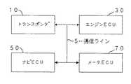
図2は、車両A内の概略的なシステム構成を示すブロック図である。トランスポンダ10はレシーバBからの要求を受け、車載制御ユニットであるエンジンECU30、ナビECU50、メータECU70から必要な情報を通信ライン5を介して入手し、その入手した情報をレシーバB(図1参照)に対して送信する。
【0030】
エンジンECU30は、エンジンの制御を司ると共に、エンジンのエミッションに関連する異常を自己診断し、トランスポンダ10の要求に応じてその情報をトランスポンダ10に送信する。
また、ナビECU50、メータECU70は、それぞれナビゲーション制御、メータ表示制御を実行すると共に、エンジンECU30が自己診断にて何らかの異常を検出したときに、エンジンECU30から出される要求に応じてそれぞれ車両の走行距離,車両位置をエンジンECU30に出力し、またトランスポンダ10からの要求が来たときにそのときの走行距離,車両位置をトランスポンダ10に出力する。
【0031】
図3〜図6はトランスポンダ10,及び各車載制御ユニットである各ECU30,50,70の構成を示すブロック図である。
まず、図3を参照してトランスポンダ10について説明する。
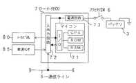
トランスポンダ10が動作するための電力を供給する電源回路13には、バッテリ3から常時電力が供給されているので、車両のキーSWの状態に関係なく動作する。マイコン11内のCPUは、同じくマイコン11内のROMに記憶された制御プログラムに従い、アンテナ20を介して外部から来る要求に応じた処理を実行する。また、マイコン11内のRAMはエンジンECU30などからのデータ等を一時的に記憶する。なお、入出力回路12がアンテナ20及び通信ライン5と接続されており、この入出力回路12を介して入出力されたデータはマイコン11内のI/Oを介してCPUなどをやりとりされる。また、マイコン11にはEEPR0M14が接続されていて、車両固有の識別番号(VINコード)が記憶されている。
【0032】
次に、図4を参照してエンジンECU30について説明する。
エンジンECU30は、メイン電源回路33がイグニッションSW4を介してバッテリ3と接続されており、基本的には、イグニッションSW4が投入されることによってメイン電源回路33から電源が供給されて動作する。但し、イグニッションSW4を介さずバッテリ3と直接つながるサブ電源回路34からマイコン31に電源供給されることで、マイコン31のRAMのデータがイグニッションSW4のオフ後も保持されることとなる。
【0033】
なお、バッテリ3は、エンジンが駆動することによって充電される構成となっている。具体的には、エンジンによって駆動されるオルタネータを備えており、そのオルタネータがエンジン回転数に応じた電力を発生し、発生した電力がバッテリ3に供給されるよう構成されている。この供給された電力によってバッテリ3が充電される。
【0034】
マイコン31では、CPUがROMに記憶された制御プログラムに従い、入出力回路32及びマイコン31内のI/Oを介して入力したセンサ信号に基づいてエンジンが最適な動作をするようインジェクタ47やイグナイタ48を制御する信号を出力する。また、エンジンのエミッションに関連する異常を自己診断してエンジンの動作やセンサ41〜46の異常等を診断し、外部(DIAGテスタ49やトランスポンダ10)からの要求に応じて診断結果のデータを出力する。また、マイコン31内のRAMは、CPUでの演算処理に使うセンサデータ、演算にて求まった制御データ、あるいは上記診断にて得た種々の診断データ等を保持している。
【0035】
なお、入出力回路32に接続されているセンサ41〜46は、空燃比(A/F)センサ41、エンジンの回転数を検出する回転センサ42、エアフローメータ43、水温センサ44、スロットルセンサ45、スタータSW46である。
次に、図5を参照してナビECU50について説明する。
【0036】
ナビECU50は、電源回路53がアクセサリSW6を介してバッテリ3と接続されており、アクセサリSW6が投入されることによってマイコン51や入出力回路52が動作する。この入出力回路52には、受信機62、地図データ入力装置64及び表示モニタ66が接続されている。受信機62にはGPSアンテナ60が接続されており、これらは、GPS衛星からの電波に基づいて車両の位置を検出するGPS(Global Positioning System )のための構成である。また、地図データ入力装置64は、位置検出の精度向上のためのいわゆるマップマッチング用データ、地図データを含む各種データを記憶媒体から入力するための装置である。このための記憶媒体としては、そのデータ量からCD−ROMを用いるのが一般的であるが、例えばDVDやメモリカード等の他の媒体を用いても良い。また、表示モニタ66は地図や誘導経路などを表示するためのものであり、本実施例では、利用者からの指示を入力する機能も備えている。
【0037】
マイコン51では、CPUがROMの記憶された制御プログラムに従い、入出力回路52及びマイコン51内のI/Oを介して入力した地図データ入力装置64からの地図データや受信機62からの信号をもとに、表示モニタ66から得られる利用者からの指示情報に対応して表示処理を実行し、表示モニタ66に利用者が所望する情報を表示させる。また、マイコン51は、エンジンECU30やトランスポンダ10からの要求が通信ライン5を介して来たときには、受信した時点の車両位置を、要求してきたエンジンECU30やトランスポンダ10に出力することができる。
【0038】
次に、図6を参照してメータECU70について説明する。
メータECU70は、電源回路73がアクセサリSW6を介してバッテリ3と接続されており、アクセサリSW6が投入されることによってマイコン71や入出力回路72が動作する。この入出力回路72には、メータパネル80や車速センサ85などが接続されている。
【0039】
マイコン71では、CPUがROMに記憶された制御プログラムに従い、車速センサ85などのセンサ信号を入力し、メータパネル80に車速などの情報を表示させる。また、マイコン71は、エンジンECU30やトランスポンダ10からの要求が通信ライン5を介して来たときには、受信した時点の車両の累積走行距離を、要求してきたエンジンECU30やトランスポンダ10に出力することができる。
【0040】
次に、上述した構成のエンジンECU30にて実行される処理について、図7〜図11を参照して説明する。
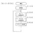
まず、エンジンECU30では、イグニッションSW4(図4参照)が投入されることによって動作を開始すると、図7のメイン処理の最初のステップS100に示すように、RAM内の検出データやカウンタデータなどの初期化を行う。なお、後述する自己診断(ダイアグ)処理(S400)に関連して記憶されるデータはこの初期化の対象外である。
【0041】
このS100での初期化処理後は、S200にて燃料噴射(EFI)、S300にて点火時期(ESA)の制御処理、S400にてエンジン関連の自己診断(ダイアグ)処理、その他の処理を繰り返し実行する。
続いて、S400でのダイアグ処理について図8及び図9を参照して詳しく説明する。
【0042】
図8に示すダイアグ処理は、例えば64ms毎に実行されるべース処理であるが、スロットルセンサ45や水温センサ44(図4参照)が異常かどうかを判断し(S410,S430)、異常を検出した場合には(S410:YES;S430;YES)、検出した異常対象を特定するコードをRAMに記憶する(S420,S440)。また、エンジンの失火を検出したかどうかを判断し(S450)、失火を検出した場合には(S450:YES)、失火コードをRAMに記憶する(S460)。なお、図8においては特には示していないが、エンジン関連部品、例えばインジェクタ47や触媒などの不良状態などを判断して、異常を検出した場合には検出した異常対象を特定するコードをRAMに記憶するようにしてもよい。
【0043】
また、図9に示すダイアグ処理も、例えば64ms毎に実行されるべース処理であり、まず最初のステップS510では、図8のダイアグ処理にて異常を検出したかどうかを判断する。具体的には、S410,S430,S450にて肯定判断された場合には、異常があったと判断する。
【0044】
異常がなければ(S510:NO)、そのまま処理ルーチンを終了するが、異常があった場合には(S510:YES)、それが検出済みの異常であるかどうかを判断する(S520)。つまり、検出した異常が、以前検出済みの異常であった場合には(S520:YES)、そのまま本処理ルーチンを終了する。一方、初めて検出した異常であった場合、つまりそれまではRAMに異常コードが記憶されていなかった場合には(S520:NO)、S530へ移行して運転状態の記憶を行う。
【0045】
このS530にて記憶される運転状態のデータ(フリーズフレームデー夕)は、車両を診断する際の異常解析用として使われるものであり、トランスポンダ10からレシーバBを介して管理センタC側(図1参照)に送られるデータの一部である。記憶される項目としては、エンジン回転数、吸入空気量、水温、スロットル開度、噴射量に関する制御データ、点火時期に関する制御データ、車両の走行距離、車両の位置などである。この内、走行距離及び車両の位置については、エンジンECU30から通信ライン5を介してメータECU70及びナビECU50に要求し、メータECU70からはその時点での累積走行距離、ナビECU50からはその時点での位置を出力してもらうことによって入手する。なお、エンジンECU30からの要求に応じてメータECU70がその時点での累積走行距離を出力する処理は図15、エンジンECU30からの要求に応じてナビECU50がその時点での位置情報を出力する処理は図17を参照して後述する。
【0046】
エンジンECU30は、上述のようにしてダイアグに関する処理が実行されて異常の有無や異常の内容や異常発生時の運転状態が記憶されていくのであるが、本実施例におけるエンジンECU30は、イグニッションSW4がオフされた後は上述のように動作を停止する。そのため、トランスポンダ10がレシーバBから要求をいつでも受け付けることができるよう、エンジンECU30はその動作中の所定間隔毎に、自らから記憶している異常に関する上記情報を通信ライン5を介してトランスポンダ10へ出力する。
【0047】
そのトランスポンダ10への異常情報出力処理について図10を参照して説明する。
図10に示す異常情報出力処理は、例えば1024ms毎に実行されるべース処理であり、まず送信待ちカウンタCaが60以上であるかどうかを判断している(S610)。そして、送信待ちカウンタCaが60以上であれば(S610:YES)、S620へ移行し、S620〜S640の各条件が成立すればS650にて異常情報をトランスポンダ10へ出力するが、送信待ちカウンタCaが60未満であれば(S610:NO)、その送信待ちカウンタCaをインクリメント(Ca←Ca+1)するだけで(S670)、本処理を終了する。
【0048】
このように、本異常情報出力処理では、異常に関する情報は頻繁には変化するものではないとの考えに基づき、エンジンECU30が実行する各種のエンジン制御処理よりも低い優先度の処理とするために、その実行間隔(1024ms毎)を他の処理よりも長く設定して処理負荷を低減している。さらに、通信ライン5上の通信量を減らすため、上述したS610に示すように、送信待ちカウンタCaにて60回毎に送信している。つまり、この実施例では約1分毎に異常に関する情報が通信ライン5を介してエンジンECU30からトランスポンダ10へ送信されることとなる。
【0049】
続いて、送信待ちカウンタCaが60以上である場合(S610:YES)に移行するS620以降の処理について説明する。
この場合は、エンジン高回転時か(S620)、エンジン高負荷時、つまりスロットル開度が所定量以上かどうか(S630)、エンジン始動時か(S620)をそれぞれ判断し、該当状態でなければ順番に次のステップに進んでいく。そして、いずれかの状態に該当した場合、つまり、マイコン31の動作が忙しいエンジン高回転状態(S620:YES)あるいは高負荷状態(S630:YES)である場合、またはエンジン始動時である場合(S640:YES)には、本処理ルーチンを終了する。一方、いずれの状態でもない場合には、次ステップのS650に移行する。
【0050】
S650では、記憶されている異常情報(異常の有無、異常がある場合には異常対象のコード、その異常を検出した時点の運転状態データなど)をトランスポンダ10へ出力する。その後は、S660にて送信待ちカウンタCaをクリアして本処理ルーチンを終了する。
【0051】
このように、本処理においては、送信待ちカウンタCaが60以上となった場合に初めてS620に移行し、常情報の出力に適した期間であるかどうかの判断処理(S620〜S640)を実行するようにしており、送信待ちカウンタCaが60未満の場合には、単に送信待ちカウンタCaをインクリメントするだけである(S670)。これは、エンジンが高回転や高負荷の状態ではエンジンECU30の処理負荷が極めて高いので、異常情報の出力によって本来のエンジン制御処理に遅れが生じてしまうことを防ぐためである。特に、異常が検出されていて出力するデータが多量な場合には出力処理で他の処理が待たされる時間が長くなるが、エンジンECU30の処理負荷が小さい状態を見計らって出力すれば、通常の制御に支障を与えない。さらに、異常情報の出力は特に急を要するものではないので、少しぐらい遅らせても問題とはならない。
【0052】
また、このようにエンジンECU30の処理負荷が小さい状態(S620及びS630にて共にNO)であっても、エンジン始動時であれば(S640:YES)、やはり異常情報の出力は実行しない。これは、エンジン始動時はノイズ環境が悪いと想定されるので、このような状況での通信を避けることで、誤データがトランスポンダ10に送られてしまうことを防止している。
【0053】
次に、上述した構成のトランスポンダ10にて実行される処理について、図11〜図14を参照して説明する。
まず、図11に示す処理は、受信割込によって実行される処理であり、最初のステップS1010では、レシーバB(図1参照)からの異常情報の送信要求であるかどうかを判断する。異常情報の送信要求である場合には(S1010:YES)、送信要求フラグF(rq)を1にセットした上で(S1020)、ナビECU50には現在の車両位置を出力するよう要求し(S1030)、メータECU70には現在の累積走行距離を出力するよう要求する(S1040)。このS1040にて出力要求をした後、あるいは上述のS1010にて否定判断された場合には、本処理ルーチンを終了し、以前の処理に復帰する。
【0054】
また、図12に示す処理も、受信割込によって実行されるものであり、受信データを格納する処理を示している。
最初のステップS1110では、エンジンECU30からの情報出力であるかどうかを判断し、そうであれば(S1110:YES)、S1120へ移行してRAM内の所定の記憶領域D(EG)に受信データを記憶する。ここでの受信データは、上述した図10のS650にてエンジンECU30から出力された異常情報である。
【0055】
一方、エンジンECU30からの情報出力でない場合は(S1110:NO)、メータECU70からの情報出力であるかどうかを判断し(S1130)、そうであれば(S1130:YES)、S1140へ移行してRAM内の所定の記憶領域D(MT)に受信データを記憶する。ここでの受信データは、上述した図11のS1040にて行った走行距離情報の出力要求に応じてメータECU70から応答出力されたものである。
【0056】
さらに、メータECU70からの情報出力でもない場合は(S1130:NO)、ナビECU50からの情報出力であるかどうかを判断し(S1150)、そうであれば(S1150:YES)、S1160へ移行してRAM内の所定の記憶領域D(NV)に受信データを記憶する。ここでの受信データは、上述した図11のS1030にて行った位置情報の出力要求に応じてナビECU50から応答出力されたものである。
【0057】
S1120,S1140,S1160に示すように、エンジンECU30、メータECU70、ナビECU50からの受信データをRAM内の記憶領域D(EG),D(MT),D(NV)に記憶させた後、あるいはS1150にて否定判断された場合には、本処理ルーチンを終了し、以前の処理に復帰する。
【0058】
一方、図13に示す出力許可フラグセット処理は、例えば256ms毎に実行されるべース処理である。
この処理は、次の点を考慮したものである。つまり、上述したハード構成の説明でも述べたが、ナビECU50及びメータECU70は、共にアクセサリSW6がオフとなると動作が停止するので、その動作停止中にレシーバBから要求があっても、その時点での情報取得はできない。そのため、所定期間内にナビECU50及びメータECU70から情報を受信できなかった場合には、各ECU50,70は動作停止状態にあると判断し、それぞれの情報の受信完了に応じてセットされる出力許可フラグF(nv),F(mt)をセットする。このフラグがセットされていれば、それ以前に受信し、RAM内の所定の記憶領域D(NV),C(MT)に記憶されていた受信データを、レシーバBへの送信用のデータとして用いることができる。
【0059】
具体的な処理内容を説明する。まず最初のステップS1210では、送信要求フラグF(rq)がセットされているかどうかを判断する。上述した図11のS1020にて送信要求フラグF(rq)がセットされていると、このS1210にて肯定判断となるため、S1220へ移行し、ナビECU50から位置情報を受信済みであるかどうかを判断する。この受信済みかどうかは、上述した図12の受信データ格納処理にてS1160での記憶領域D(NV)に受信データを記憶する処理が実行されたかどうかで判断する。
そして、ナビECU50からの受信データを記憶済みの場合には(S1220:YES)、S1250へ移行して、受信完了に応じてセットされる出力許可フラグF(nv)をセットする。一方、受信データを記憶済みでなければ(S1220:NO)、カウンタCnvをインクリメントした上で(S1230)、そのカウンタCnvが40以上かどうかを判断する(S1240)。そして、カウンタCnvが40以上であれば(S1240:YES)、S1250へ移行して出力許可フラグF(nv)をセットするが、カウンタCnvが40未満であれば(S1240:NO)、S1250の処理を実行することなく、S1260へ移行する。
【0060】
S1260〜S1290においては、上述したS1220〜S1250にて実行したナビECU50に関する処理と同様の処理を、メータECU70に関する処理として実行する。つまり、メータECU70から走行距離情報を受信済みであるかどうかを判断し(S1260)、受信済みである場合には(S1260:YES)、S1290へ移行して、受信完了に応じてセットされる出力許可フラグF(mt)をセットする。一方、受信データを記憶済みでなければ(S1260:NO)、カウンタCmtをインクリメントした上で(S1270)、そのカウンタCmtが40以上かどうかを判断する(S1280)。そして、カウンタCmtが40以上であれば(S1280:YES)、S1290へ移行して出力許可フラグF(mt)をセットするが、カウンタCnvが40未満であれば(S1280:NO)、S1290の処理を実行することなく、本処理ルーチンを終了する。
【0061】
続いて、図14に示す送信処理ルーチンについて説明する。この送信処理は、例えば256ms毎に実行されるベース処理であり、まず、最初のステップS1310では送信要求フラグF(rq)が1にセットされているかどうか判断する。そして、送信要求フラグF(rq)が1にセットされていれば(S1310:YES)、続くS1320にて、出力許可フラグF(nv),F(mt)が共に1にセットされているかどうか判断する。
【0062】
そして、出力許可フラグF(nv),F(mt)が共に1にセットされていれば(S1320:YES)、診断データとしてRAM内の記憶領域D(EG),D(MT),D(NV)に格納されている受信データを、EEPROM14(図3参照)に記憶しているVINコードと共に、レシーバBに対して送信する。さらに、送信要求フラグF(rq)、出力許可フラグF(nv),F(mt)を0にセット、つまりクリアして(S1340)、本処理ルーチンを終了する。
【0063】
なお、送信要求フラグF(rq)が0の場合(S1310:NO)、あるいは出力許可フラグF(nv),F(mt)のいずれか一方でも0である場合は(S1320:NO)、そのまま本処理ルーチンを終了する。
次に、メータECU70にて実行される処理について図15,16を参照して説明する。
【0064】
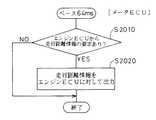
図15に示す処理は、例えば64ms毎に実行されるベース処理であり、まず、最初のステップS2010にて、エンジンECU30から走行距離情報の要求があったかどうか判断し、要求があれば(S2010:YES)、その時点での走行距離情報をエンジンECU30に対して出力する(S2020)。このエンジンECU30から走行距離情報の要求は、上述した図9のS530の処理中にて出されるものである。そして、S2020で出力した走行距離情報は、同じく図9のS530の処理中において記憶されることとなる。
【0065】
一方、図16に示す処理も、例えば64ms毎に実行されるベース処理であるが、上記図15の処理がエンジンECU30からの要求に応答する処理であったのに対して、この図16の処理は、トランスポンダ10からの要求に応答したり、あるいは自発的に情報を出力する処理である。
【0066】
まず、最初のステップS2110にて、トランスポンダ10から走行距離情報の要求があったかどうか判断し、要求があれば(S2110:YES)、その時点での走行距離情報をエンジンECU30に対して出力し(S2140)、さらに、送信完了フラグF(TP)を1にセットして、本処理ルーチンを終了する。
【0067】
これが応答処理としての基本であるが、トランスポンダ10から走行距離情報の要求がない場合であっても(S2110:NO)、車速が0であり(S2120:YES)、さらに送信完了フラグF(TP)が0であれば(S2130:YES)、走行距離情報をエンジンECU30に対して出力するようにしている(S2140)。つまり、メータECU70は、アクセサリSW6がオフとなると動作が停止するので、その動作停止中にトランスポンダ10から要求されても応答できない。そのため、動作中は、トランスポンダ10からの要求がなくても、車速が0、つまり車両停止を検出する毎に1回、自発的にトランスポンダ10へその時点での走行距離情報を出力するようにしている。
【0068】
なお、図16のフローチャートにおいては、S2120にて否定判断、つまり車速が0でない場合はS2160へ移行して送信完了フラグF(TP)をクリアしており、また、S2130にて否定判断、つまり車速が0であっても(S2120:YES)、送信完了フラグF(TP)が1にセットされている場合はそのまま本処理ルーチンを終了する。これらは、上述したように、基本的にはトランスポンダ10からの要求に応答し、その要求がない場合であっても車両停止を検出する毎に1回だけ自発的にトランスポンダ10へ情報出力させるための処理である。
【0069】
次に、ナビECU50にて実行される処理について図17,18を参照して説明する。
図17に示す処理は、例えば64ms毎に実行されるベース処理であり、まず、最初のステップS3010にて、エンジンECU30から位置情報の要求があったかどうか判断し、要求があれば(S3010:YES)、その時点での位置情報をエンジンECU30に対して出力する(S3020)。このエンジンECU30から位置情報の要求は、上述した図9のS530の処理中にて出されるものである。そして、S3020で出力した位置情報は、同じく図9のS530の処理中において記憶されることとなる。
【0070】
一方、図18に示す処理も、例えば64ms毎に実行されるベース処理であるが、上記図17の処理がエンジンECU30からの要求に応答する処理であったのに対して、この図16の処理は、トランスポンダ10からの要求に応答したり、あるいは自発的に情報を出力する処理である。
【0071】
まず、最初のステップS3110にて、トランスポンダ10から位置情報の要求があったかどうか判断し、要求があれば(S3110:YES)、その時点での位置情報をエンジンECU30に対して出力し(S3140)、さらに、送信完了フラグF(TP)を1にセットして、本処理ルーチンを終了する。
【0072】
これが応答処理としての基本であるが、トランスポンダ10から位置情報の要求がない場合であっても(S2110:NO)、車速が0であり(S3120:YES)、さらに送信完了フラグF(TP)が0であれば(S3130:YES)、位置情報をエンジンECU30に対して出力するようにしている(S3140)。ナビECU50も、アクセサリSW6がオフとなると動作が停止するので、その動作停止中にトランスポンダ10から要求されても応答できない。そのため、動作中は、トランスポンダ10からの要求がなくても、車速が0、つまり車両停止を検出する毎に1回、自発的にトランスポンダ10へその時点での位置情報を出力するようにしている。
【0073】
なお、図18のフローチャートにおいて、車速が0でない場合(S3120:NO)にS2160へ移行して送信完了フラグF(TP)をクリアし、また、車速が0であっても(S3120:YES)、送信完了フラグF(TP)が1にセットされている場合は(S3130:NO)、そのまま本処理ルーチンを終了する。これらは、基本的にはトランスポンダ10からの要求に応答し、その要求がない場合であっても車両停止を検出する毎に1回だけ自発的にトランスポンダ10へ情報出力させるための処理である。
【0074】
これら図16及び図18を参照して説明したように、メータECU70あるいはナビECU50の動作停止があったとしても、動作中に車速が0(車両停止)になった場合には、走行距離情報あるいは位置情報がトランスポンダ10へ出力されるので、仮に動作中にトランスポンダ10からの出力要求が全くなかったとしても、各情報はトランスポンダ10において確実に記憶される。また、アクセサリSW6がオフされるのは、基本的には車両停止時にしかあり得ないため、その状況においてのみ情報出力することで、不必要な送信をなくすことができる。さらに、車両停止中は基本的に走行距離情報や位置情報が変化することはないので、車両停止時のみに情報を出力すれば、実状に合致した適切な情報がトランスポンダ10に記憶されることとなる。
【0075】
以上説明した処理を実行することによって、トランスポンダ10からレシーバBへは、異常が検出された時点の車両位置,累積走行距離と、レシーバBが車両に異常情報の送信を要求した時点の車両位置,累積走行距離とが送られることとなるので、レシーバBからデータを転送された管理センタCでは、異常となってからの車両Aの走行距離や移動状況がわかる。したがって、車両Aのユーザーに対して適切な処置を取ることができる。この適切な処置とは、例えば警告を通知したり、場合によっては通信を介して車両Aが安全な場所で停止した時点で強制的にエンジンを停止させるようにしたり、エンジンがユーザーにより切られた時に再度エンジンがかからなくなるようにするなどである。
【0076】
このように、本実施例の車両用診断装置によれば、車両Aに搭載された「制御ユニット」としての各ECU30,50,70がそれぞれ管轄する各種機器の状態を診断し、その診断結果は、通信ライン5で接続された「通信ユニット」としてのトランスポンダ10によって外部のレシーバBに送信され、さらに管理センタCへ転送される。これら各ECU30,50,70及びトランスポンダ10は、車載エンジンの駆動によって充電されるバッテリ3から供給された電力によって動作するが、バッテリ3からトランスポンダ10へは通常動作に必要な電力が常時供給されるよう構成されているため、トランスポンダ10は、レシーバBからの送信要求がいつ来ても、それに応じて診断結果を送信することができる。
【0077】
一方、バッテリ3から各ECU30,50,70へはイグニッションSW4あるいはアクセサリSW6によって、通常動作に必要な電力が供給される状態と供給されない状態とが切り替え可能に構成されている。そして、車両使用中は、イグニッションSW4あるいはアクセサリSW6はオンされるので、通常動作に必要な電力がバッテリ3から供給される。一方、車両不使用中は、イグニッションSW4及びアクセサリSW6は共にオフされるため、通常動作に必要な電力がバッテリ3からは供給されない。この意味で、エンジンECU30に対するイグニッションSW4、ナビECU及びメータECU70に対するアクセサリSWが、それぞれ「供給状態設定手段」に相当する。
【0078】
したがって、車両不使用中で車載エンジンが停止しておりバッテリ3が充電されない状況では、各ECU30,50,70への電力供給が低減される。具体的には、エンジンECU30のサブ電源回路34(図4参照)を介してマイコン31内のRAMに格納されたデータを保持するためだけの電力供給がなされるだけであるので、バッテリ3の消耗が相当少なくなる。
【0079】
つまり、いつ来るか判らないレシーバBからの送信要求に対して、いつ来てもそれに応答できるようにするため、トランスポンダ10に加えて各ECU30,50,70までも通常動作できるように準備しておくのはバッテリ消耗の点からすれば非合理的である。そこで、上記送信要求に応答するためだけであれば最低限トランスポンダ10だけ動作できればよいので、各ECU30,50,70への通常動作可能な電力の供給はしない。
【0080】
但し、車両不使用中は各ECU30,50,70へ通常動作可能な電力が供給されないため、その車両不使用中にレシーバBから送信要求があった場合、その時点で各ECU30,50,70からの情報を取得することはできない。したがって、トランスポンダ10は、その時点で各ECU30,50,70からの情報を取得する代わりに、車両Aが不使用状態になる以前の車両使用中に各ECU30,50,70から得た最新の情報を送信する。
【0081】
これによって、レシーバBからの送信要求がいつ来ても応答できるように構成されていながら、バッテリ消耗を極力少なくすることができる。
また、本実施例では、エンジンECU30からの診断結果は、エンジンECU30が主導で出力している。つまり、トランスポンダ10からの要求ではなく、所定時間毎に異常情報を出力することを基本としている(図10参照)。但し、その出力に不適切な期間は避けるようにしている。まず、エンジン高回転あるいは高負荷時で制御に要する処理負荷が大きいと考えられる期間である。エンジンに対する各種制御が本来の仕事であり、優先度は相対的に高く、一方、異常情報の出力は相対的に見れば優先度が低い。つまり、エンジンECU30が優先度の高い処理を実行するのに忙しい期間中においては、その優先度の高い処理を抑えてまで、あえて異常情報の出力という優先度の低い処理を実行する必要性はない。したがって、このような期間中にトランスポンダ10へ診断結果を出力する要求があっても、その要求には対応しない。さらに、エンジン始動に起因して通信ライン5上にノイズが発生していると考えられる期間もトランスポンダ10へ異常情報を出力しない。エンジン始動時はスタータを回転駆動させていることなどよって通信ライン5上にノイズが発生している可能性が高い。そのため、この状態でエンジンECU30からトランスポンダ10に異常情報が出力されると、通信ライン上5でデータ化けやデータ破壊が起こり、エンジンECU30から出力されたのとは違う誤った診断結果が管理センタCに送信されてしまう可能性がある。したがって、このような期間中にトランスポンダ10へ診断結果を出力する要求があっても、その要求には対応しない。
[その他]
(1)トランスポンダ10が各ECU30,50,70から取得する情報について考えてみる。
【0082】
上記実施例においては、エンジンECU30は自己の管理するタイミングにて異常情報を出力するようにしており、またナビECU50及びメータECU70は、基本的にはトランスポンダ10からの要求に応じて情報を出力するが、車両が停止した場合には、その時点で自発的に情報を出力する。したがって、車両不使用中にレシーバBからの送信要求があった場合、トランスポンダ10には、車両使用中において各ECU30,50,70から上述のタイミングで出力された最後の情報が記憶されていることとなる。その記憶された情報を「最新の診断結果」としてレシーバBに送信する。
【0083】
これ以外に次のようにすることも考えられる。例えばエンジンECU30について考えると、イグニッションSW4がオフされた時点から所定期間はエンジンECU30の通常動作に必要な電力が供給されている状態を継続することで、その所定期間中にエンジンECU30から異常情報を出力させるのである。例えば図4に示すサブ電源回路34から供給される電力によって、その異常情報出力処理を実行する。また、ナビECU50やメータECU70の場合にも同様にサブ電源回路を追加すればよい。
【0084】
もちろん、このようなサブ電源回路によって実現するのではなく、例えば車両運転手によるキー操作にてイグニッションSW4がオフされたりアクセサリW6がオフされた場合、そのオフ操作時点から所定の遅延時間後にバッテリ3から電源回路33,53,73への実際の電力供給を遮断するようにしてもよい。例えば、バッテリ3と電源回路33,53,73との間にイグニッションSW4ヤアクセサリSW6を迂回した電源ラインを設け、そのライン上に設けたリレーを、マイコンがイグニッションSW4やアクセサリSW6の状態に応じて制御するように構成すればよい。
【0085】
つまり、車両の使用状態から不使用状態への切り替わりタイミングは、運転手のキー操作によって定まるため、実際の電力供給停止をその切り替わりタイミングから遅延させればよい。
このようにすれば、「最新の診断結果」としてより適切なものが得られる。つまり、各ECU30,50,70から自発的に出力される情報の内の最後のものを「最新の診断結果」とする場合、出力間隔によっては、車両Aが使用状態から不使用状態に切り替わる直前の状態を反映した情報とはならない可能性もある。例えば、最後の情報を出力した後でも車両が走行している場合もあり、その走行によって新たな異常が発生する可能性もある。また、新たな異常がなくても、最終的に停止した時点の位置情報や走行距離情報との誤差が生じる可能性もある。そのため、上述の手法を採用すれば、車両が実際に停止した時点での位置情報や走行距離情報が得られる点で有利である。
【0086】
(2)また、上記実施例においては、エンジンECU30は自己の管理するタイミングにて異常情報を出力するようにしていたが、例えばトランスポンダ10から定期的あるいは非定期的に要求を出し、その要求に応じてエンジンECU30から異常情報を出力するようにしてもよい。
【0087】
そして、このように、エンジンECU30がトランスポンダ10からの要求に応じて異常情報を出力する場合には、上述した処理負荷が大きい期間やエンジン始動時のように異常情報の出力に不適切な期間への対処が問題となるが、やはりそれら不適期間中には応答しない、つまり異常情報は出力しないようにする。そして、例えば、不適期間中にトランスポンダ10から出力要求があった場合には、その要求には対応しないが、要求があったこと自体は記憶しておき、その後、不適期間に該当しない状況となった時点で、記憶されている診断結果の出力要求に応じて、異常情報をトランスポンダ10へ出力することが考えられる。
【0088】
このようにすれば出力要求へのレスポンスは向上する。なぜなら、出力要求が来た時点で不適期間中であるかどうかを判断し、不適期間中であれば対応せず、不適期間中でなければ対応するだけの場合には、不適期間が過ぎていても、その後に出力要求が来るタイミングを待たなくてはならない。つまり、必ずしも不適期間が過ぎた直後に出力要求が来るとは限らないからである。それに対して、診断結果の出力要求があったこと自体は記憶しておき、その後、不適期間に該当しない状況となった時点で出力要求に応じるようにすれば、対応して良い状態になったら即座に応じることができるため、出力要求へのレスポンスは向上する。
【0089】
(3)上記(2)のようにエンジンECU30がトランスポンダ10からの出力要求に応じてトランスポンダ10へ診断結果を出力することを前提とした場合には、次のような工夫も有効である。
つまり、トランスポンダ10が、エンジンECU30から診断結果が複数回出力され、かつ複数回の診断結果の内容が一致するまで、繰り返しエンジンECU30へ出力要求し、診断結果が一致すると、その一致した診断結果を管理センタ側へ送信するよう構成することが考えられる。エンジンECU30からトランスポンダ10に出力された診断結果の正確性向上を期すためには、有効である。
【0090】
また、トランスポンダ10に異常がある場合のエンジンECU30側の対処としては、次のようにすることも有効である。つまり、トランスポンダ10からの要求に応じて診断結果を所定回数以上出力したにもかかわらず、さらに診断結果の出力要求が来た場合には、それ以降の要求には対応しないようにする。
【図面の簡単な説明】
【図1】 実施例の車両用診断装置の搭載された車両を含む診断システムの概略説明図である。
【図2】 実施例の車両内の概略的なシステム構成を示すブロック図である。
【図3】 実施例のトランスポンダの構成を示すブロック図である。
【図4】 実施例のエンジンECUの構成を示すブロック図である。
【図5】 実施例のナビECUの構成を示すブロック図である。
【図6】 実施例のメータECUの構成を示すブロック図である。
【図7】 実施例のエンジンECUで実行されるメイン処理を示すフローチャートである。
【図8】 実施例のエンジンECUで実行されるダイアグ処理を示すフローチャートである。
【図9】 実施例のエンジンECUで実行されるダイアグ処理を示すフローチャートである。
【図10】 実施例のエンジンECUで実行される異常情報出力処理を示すフローチャートである。
【図11】 実施例のトランスポンダで受信割込にて実行される処理を示すフローチャートである。
【図12】 実施例のトランスポンダで受信割込にて実行される受信データ格納処理を示すフローチャートである。
【図13】 実施例のトランスポンダで実行される出力許可フラグセット処理を示すフローチャートである。
【図14】 実施例のトランスポンダで実行される送信処理を示すフローチャートである。
【図15】 実施例のメータECUで実行されるエンジンECUへの出力処理を示すフローチャートである。
【図16】 実施例のメータECUで実行されるトランスポンダへの出力処理を示すフローチャートである。
【図17】 実施例のナビECUで実行されるエンジンECUへの出力処理を示すフローチャートである。
【図18】 実施例のナビECUで実行されるトランスポンダへの出力処理を示すフローチャートである。
【符号の説明】
3…バッテリ 4…イグニッションSW
5…通信ライン 6…アクセサリSW
10…トランスポンダ 11…マイコン
12…入出力回路 13…電源回路
20…アンテナ
30…エンジンECU 31…マイコン
32…入出力回路 33…メイン電源回路
34…サブ電源回路 41…A/Fセンサ
42…回転センサ 43…エアフローメータ
44…水温センサ 45…スロットルセンサ
46…スタータSW 47…インジェクタ
48…イグナイタ 49…DIAGテスタ
50…ナビECU 51…マイコン
52…入出力回路 53…電源回路
60…GPSアンテナ 62…受信機
64…地図データ入力装置 66…表示モニタ
70…メータECU 71…マイコン
72…入出力回路 73…電源回路
80…メータパネル 85…車速センサ
A…車両 B…レシーバ
C…管理センタ[0001]
BACKGROUND OF THE INVENTION
The present invention relates to a vehicular diagnostic apparatus for diagnosing the state of various devices mounted on a vehicle, and more particularly to a vehicular diagnostic apparatus capable of transmitting a diagnosis result to an external management center side.
[0002]
[Prior art]
For example, in Japan, the maintenance of the vehicle is reported to the Land Transport Bureau by the user inspecting and repairing at a maintenance shop in response to vehicle inspections at regular intervals in Japan. According to the notice, the user is inspected and repaired at the maintenance shop, and it is managed in such a way that it returns to the supervisory station that the standard is satisfied.
[0003]
However, in such a system, since the vehicle is uniformly managed even if there is no failure or defect and no maintenance is required, the man-hours for management at the supervisory station (land transport station) are increased and it is also troublesome for the user. Is.
For this reason, information related to the inspection (for example, information related to abnormality of engine-related parts) is transmitted from the vehicle to the management center side as the supervisory station side by wireless communication, and the vehicle that needs repair in particular. Can be directed to report to the user.
[0004]
[Problems to be solved by the invention]
In such a system, the vehicle side is equipped with a device for transmitting and receiving wireless communication (hereinafter referred to as a transponder), and information related to the inspection is obtained by the in-vehicle control unit and communicated from the control unit to the transponder. It is necessary to configure as follows.
[0005]
However, the vehicle side is passive, such that the management center sends a request for transmission of information related to the inspection, and the transponder that receives the transmission request transmits information related to the inspection to the management center. In the case of the system, the following inconvenience occurs. In other words, since it is not known when a transmission request from the management center side is sent, it is necessary to construct a system on the vehicle side so that a response can be made whenever the request comes. For this purpose, for example, a vehicle-mounted transponder or control unit may be always on. However, in general, the vehicle-mounted battery is not charged when the engine is stopped. The battery is consumed in a short period of time due to the power consumed by the transponder and the control unit.
[0006]
Accordingly, an object of the present invention is to provide a vehicular diagnostic apparatus that is configured to be able to respond to a transmission request from the management center whenever it is received, while minimizing battery consumption.
[0007]
[Means for Solving the Problems and Effects of the Invention]
According to the vehicle diagnostic apparatus of
[0008]
On the other hand, a state in which power necessary for normal operation is supplied and a state in which power is not supplied can be switched from the battery to the control unit. The supply state setting means is configured to switch from the battery to the control unit during use of the vehicle. On the other hand, when the vehicle is not in use, the power is switched from the battery to the control unit so that the power required for the normal operation is not supplied. Therefore, in a situation where the vehicle is not in use and the in-vehicle engine is stopped and the battery is not charged, the power supply to the control unit is reduced (including the stop), and accordingly, battery consumption is reduced accordingly.
[0009]
In other words, in order to be able to respond to a transmission request from the management center side that does not know when it comes, it is necessary to prepare not only the communication unit but also the control unit for normal operation. In terms of battery consumption, it is irrational. Therefore, since it is sufficient that only the communication unit can operate if it is only for responding to the transmission request, power that can be normally operated is not supplied to the control unit side.
[0010]
However, when the vehicle is not in use, normally operable power is not supplied to the control unit. If there is a transmission request from the management center while the vehicle is not in use, the diagnostic result is obtained from the control unit at that time. I can't do it. Therefore,When the control unit is in a state where power necessary for normal operation is supplied, it sends a diagnostic result to the communication unit. Instead of acquiring diagnostic results from the control unit at that time, the communication unit is using the vehicle before the vehicle is not in use, specifically when the control unit is supplied with power necessary for normal operation. Obtained from the control unitHave Send the latest diagnostic results.
[0011]
Accordingly, it is possible to provide a vehicular diagnostic apparatus that is configured to be able to respond whenever a transmission request from the management center is received, while reducing battery consumption as much as possible.
The “state in which power necessary for normal operation is not supplied” is set for the following reason. For example, in order to retain the data in the RAM of the microcomputer even when the vehicle is not used, it is necessary to supply power. However, for example, considering an engine ECU as a control unit, it is unnecessary to use electric power necessary for executing normal engine control. Therefore, of course, if it is not necessary to hold such data in the RAM, the power supply may be completely stopped. However, including the above-described circumstances, “a state where power necessary for normal operation is not supplied” It was.
[0012]
In addition, the expression “in use” and “not in use” as the state of the vehicle is as follows. That is, if the engine is driven, it is always in use. For example, even if the engine is not driven, a car navigation system of an in-vehicle device can be used. This car navigation system can be used in general automobiles if the accessory switch is turned on. Therefore, the word “in use” or “not in use” is used here to include them. Specifically, in general automobiles, there are many key switches having four positions of OFF, ACC, ON, and START. In this case, only OFF is “not in use”, and the remaining ACC / ON • All START cases can be considered “in use”. That is, the case where the user of the vehicle uses on-vehicle equipment that operates on a battery is in use. Therefore, even if any on-vehicle equipment is used while the key switch is OFF, it is not in use but “not in use”.
[0013]
As for the “latest diagnosis result” transmitted by the communication unit when the vehicle is not used, for example, as shown in
[0014]
Alternatively, as shown in
[0015]
By the way, the diagnosis result output from the control unit to the communication unit is basically output during use of the vehicle. Therefore, for example, if the output timing of the diagnosis result overlaps when the engine is started, the communication state is bad, so noise gets on the communication line between the communication unit and the control unit, and for example, the signal input to the communication unit is sent from the control unit It may be different from the output signal. In that case, incorrect information is sent to the management center side. Also, when the microcomputer of the control unit (hereinafter abbreviated as “microcomputer”) is busy, for example, the engine control unit, the amount of output data to the communication unit increases at high engine speeds and high loads. May affect the original control process.
[0016]
Therefore, in order to prevent such inconvenience while obtaining the above-described effect of reducing battery consumption, the control unit of the above-described vehicle diagnostic device is inappropriate for outputting the diagnosis result to the communication unit. It is preferable to discriminate between different periods and not output during that period.
[0017]
Specifically, when the control unit is larger than a predetermined amount during the first inadequate period when it is considered that noise is generated on the communication line due to engine starting, At least one of the possible second inappropriate periods is determined, and when it is determined that the inappropriate period, the diagnosis result is not output even at the output timing to a predetermined communication unit. On the other hand, when it does not correspond to the inappropriate period, the diagnosis result is output to the communication unit at a predetermined output timing.
[0018]
During the first inadequate period described above, it is highly possible that noise is generated on the communication line due to, for example, the starter being rotationally driven due to engine start. For this reason, if a diagnostic result is output from the control unit to the communication unit in this state, data corruption or data corruption occurs on the communication line between these units, resulting in an erroneous diagnostic result different from that output from the control unit. There is a possibility of being sent to the management center. Therefore, no diagnostic result is output even if a predetermined output timing comes during such an inappropriate period.
[0019]
Further, the second inappropriate period described above is a period in which the processing load required for control of various devices is greater than a predetermined value. Control of various devices is the original work of the control unit, and the priority is relatively high, while the output of the diagnosis result is relatively low when viewed relatively. In other words, during periods when the control unit is busy executing high-priority processing (that is, when the processing load on the microcomputer is high), the priority of the diagnosis result output is intentionally suppressed until the high-priority processing is suppressed. There is no need to perform low processing. Therefore, no diagnostic result is output even if a predetermined output timing comes during such a period. Note that the state in which the processing load is large specifically refers to a state in which the engine speed is high if the control target is an engine. That is, if the processing timing corresponding to the rotational speed is set, the processing amount per unit time increases in the high engine speed state. In particular, real-time processing is required for the engine, and processing with low urgency, such as output of diagnosis results, can be done later.
[0020]
By the way, the “predetermined output timing” is based on the output request timing from the communication unit if, for example, the control unit that has received the output request from the communication unit outputs a diagnosis result. In this method, the communication unit may request the control unit to output a diagnosis result in response to a transmission request from the management center side. In this way, there is a management advantage because a transmission request can be issued at a timing convenient for management in the management center.
[0021]
As described above, when the communication unit requests the control unit to output a diagnosis result in response to a transmission request from the management center side, the control unit may respond as follows. In other words, if there is a request to output diagnostic results during the inappropriate period, it will not respond to the request, but remember that the request itself has been stored, and then the situation will not fall under the inappropriate period In response to the output request for the stored diagnosis result, the diagnosis result is output to the communication unit. This improves the response to the output request. Because it is judged whether it is in the inappropriate period when the output request comes, and if it is in the inappropriate period, it will not respond, and if it is only in the inappropriate period, the inappropriate period has passed. However, it is necessary to wait for the output request after that. That is, an output request does not always come immediately after the inappropriate period has passed. On the other hand, if the diagnosis request output request itself is memorized, and if the output request is met when the situation does not fall under the inappropriate period, then it will be possible to respond. Since it can respond immediately, the response to the output request is improved.
[0022]
As described above, when it is assumed that the control unit outputs a diagnosis result to the communication unit in response to an output request from the communication unit, the communication unit outputs the diagnosis result from the control unit a plurality of times. In addition, it is conceivable that an output request is repeatedly made to the control unit until the contents of the diagnosis results of a plurality of times match, and when the diagnosis results match, the matched diagnosis result is transmitted to the management center side. This is effective for improving the accuracy of the diagnostic result output from the control unit to the communication unit.
[0023]
In addition, as a countermeasure on the control unit side when there is an abnormality in the communication unit, the following is also effective. That is, when a diagnosis result output request is received even though the diagnosis result is output a predetermined number of times or more in response to a request from the communication unit, the subsequent request is not handled.
[0024]
In the vehicle diagnostic apparatus, the communication unit eventually transmits the vehicle diagnosis result to the management center, but it is also conceivable to include identification information unique to the vehicle in the diagnosis result. This is effective in that it is possible to easily determine which vehicle the diagnosis result corresponds to. Of course, in addition to this, a method for identifying the vehicle that has transmitted the diagnosis result is conceivable, but if it is included in the diagnosis result, the identification can be easily performed.
[0025]
It is also effective to include at least one of the travel distance of the vehicle or the vehicle position at the time of diagnosis, for example, as supplementary information in the diagnosis result, as well as information on the device to be diagnosed. That is, the analysis of the diagnosis result may change depending on the travel distance of the vehicle itself on which the device to be diagnosed is mounted. The same applies to the vehicle position.
[0026]
In the vehicle diagnostic apparatus described above, various on-vehicle devices can be controlled by the control unit.
[0027]
DETAILED DESCRIPTION OF THE INVENTION
Embodiments to which the present invention is applied will be described below with reference to the drawings. Needless to say, the embodiments of the present invention are not limited to the following examples, and can take various forms as long as they belong to the technical scope of the present invention.
[0028]
FIG. 1 is a diagram illustrating a schematic configuration of a diagnostic system including a vehicle on which the vehicle diagnostic apparatus according to the embodiment is mounted. An outline of the system will be described. The management center C that constitutes a supervisory station obtains data relating to emissions (exhaust gas), data relating to engine failure, and the like from a plurality of vehicles A via the receiver B by wireless communication. The management center C identifies the defective vehicle A and prompts the vehicle owner to repair and improve the vehicle A. It should be noted that various methods such as mailing documents can be employed to promote repair and improvement of the vehicle A.
[0029]
FIG. 2 is a block diagram showing a schematic system configuration in the vehicle A. As shown in FIG. Upon receiving a request from the receiver B, the transponder 10 obtains necessary information from the
[0030]
The
In addition, the navigation ECU 50 and the
[0031]
3 to 6 are block diagrams showing configurations of the transponder 10 and the
First, the transponder 10 will be described with reference to FIG.
Since the power supply circuit 13 that supplies power for operating the transponder 10 is always supplied with power from the
[0032]
Next, the
The
[0033]
The
[0034]
In the microcomputer 31, the injector 47 and the igniter 48 are operated so that the engine operates optimally based on the sensor signal input via the input / output circuit 32 and the I / O in the microcomputer 31 according to the control program stored in the ROM. Outputs a signal to control In addition, self-diagnosis of abnormalities related to engine emissions is performed to diagnose engine operation and abnormalities of sensors 41 to 46, etc., and output of diagnosis result data according to requests from the outside (DIAG tester 49 and transponder 10) To do. The RAM in the microcomputer 31 holds sensor data used for calculation processing by the CPU, control data obtained by calculation, various diagnostic data obtained by the above diagnosis, and the like.
[0035]
Sensors 41 to 46 connected to the input / output circuit 32 include an air-fuel ratio (A / F) sensor 41, a rotation sensor 42 for detecting the engine speed, an air flow meter 43, a water temperature sensor 44, a throttle sensor 45, This is the starter SW46.
Next, the navigation ECU 50 will be described with reference to FIG.
[0036]
In the navigation ECU 50, the
[0037]
In the microcomputer 51, the CPU receives map data from the map data input device 64 and signals from the receiver 62 input via the input /
[0038]
Next, the
The
[0039]
In the microcomputer 71, the CPU inputs sensor signals such as the vehicle speed sensor 85 according to the control program stored in the ROM, and displays information such as the vehicle speed on the meter panel 80. Moreover, when the request | requirement from engine ECU30 or the transponder 10 comes via the
[0040]
Next, processing executed by the
First, in the
[0041]
After the initialization process at S100, fuel injection (EFI) is performed at S200, ignition timing (ESA) control process at S300, engine-related self-diagnosis (diagnostic) process at S400, and other processes are repeated. To do.
Next, the diagnosis process in S400 will be described in detail with reference to FIGS.
[0042]
The diagnosis process shown in FIG. 8 is a base process executed every 64 ms, for example, but it is determined whether or not the throttle sensor 45 and the water temperature sensor 44 (see FIG. 4) are abnormal (S410, S430). If detected (S410: YES; S430; YES), a code for specifying the detected abnormality target is stored in the RAM (S420, S440). Further, it is determined whether engine misfire has been detected (S450). If misfire has been detected (S450: YES), the misfire code is stored in the RAM (S460). Although not specifically shown in FIG. 8, when a failure state of an engine-related component such as an injector 47 or a catalyst is determined and an abnormality is detected, a code for specifying the detected abnormality target is stored in the RAM. You may make it memorize | store.
[0043]
The diagnosis process shown in FIG. 9 is also a base process executed every 64 ms, for example. First, in step S510, it is determined whether an abnormality is detected in the diagnosis process of FIG. Specifically, if an affirmative determination is made in S410, S430, or S450, it is determined that there is an abnormality.
[0044]
If there is no abnormality (S510: NO), the processing routine is terminated as it is. If there is an abnormality (S510: YES), it is determined whether or not it is a detected abnormality (S520). That is, if the detected abnormality is a previously detected abnormality (S520: YES), this processing routine is terminated as it is. On the other hand, if the abnormality is detected for the first time, that is, if the abnormality code has not been stored in the RAM until then (S520: NO), the process proceeds to S530 and the operation state is stored.
[0045]
The driving state data (freeze frame data) stored in S530 is used for abnormality analysis when diagnosing the vehicle, and is sent from the transponder 10 via the receiver B to the management center C side (FIG. 1). Part of the data sent to The stored items include engine speed, intake air amount, water temperature, throttle opening, control data related to injection amount, control data related to ignition timing, vehicle travel distance, vehicle position, and the like. Of these, the travel distance and the position of the vehicle are requested from the
[0046]
The
[0047]
The abnormality information output process to the transponder 10 will be described with reference to FIG.
The abnormality information output process shown in FIG. 10 is a base process executed, for example, every 1024 ms, and first determines whether or not the transmission waiting counter Ca is 60 or more (S610). If the transmission waiting counter Ca is 60 or more (S610: YES), the process proceeds to S620. If the conditions of S620 to S640 are satisfied, abnormality information is output to the transponder 10 in S650. Is less than 60 (S610: NO), the transmission waiting counter Ca is simply incremented (Ca ← Ca + 1) (S670), and this process is terminated.
[0048]
In this way, in this abnormality information output process, based on the idea that information relating to abnormality does not change frequently, in order to make the process a lower priority than the various engine control processes executed by the
[0049]
Next, the processing after S620 that is shifted to the case where the transmission waiting counter Ca is 60 or more (S610: YES) will be described.
In this case, it is determined whether the engine is at a high speed (S620), the engine is highly loaded, that is, whether the throttle opening is equal to or larger than a predetermined amount (S630), and the engine is started (S620). Proceed to the next step. And when it corresponds to either state, that is, when the operation of the microcomputer 31 is busy, the engine is in a high rotation state (S620: YES) or a high load state (S630: YES), or when the engine is starting (S640). : YES), this processing routine ends. On the other hand, if neither state is found, the process proceeds to S650 in the next step.
[0050]
In S650, the stored abnormality information (whether there is an abnormality, if there is an abnormality, the code of the abnormality target, the operation state data at the time when the abnormality is detected, etc.) is output to the transponder 10. Thereafter, the transmission waiting counter Ca is cleared in S660, and this processing routine is ended.
[0051]
As described above, in this process, when the transmission waiting counter Ca becomes 60 or more, the process proceeds to S620 for the first time, and a determination process (S620 to S640) is performed to determine whether it is a period suitable for normal information output. When the transmission waiting counter Ca is less than 60, the transmission waiting counter Ca is simply incremented (S670). This is because the processing load of the
[0052]
Even when the processing load on the
[0053]
Next, processing executed by the transponder 10 having the above-described configuration will be described with reference to FIGS.
First, the process shown in FIG. 11 is a process executed by a reception interrupt. In the first step S1010, it is determined whether or not it is a transmission request for abnormal information from the receiver B (see FIG. 1). If the transmission request is abnormal information (S1010: YES), the transmission request flag F (rq) is set to 1 (S1020), and the navigation ECU 50 is requested to output the current vehicle position (S1030). ), The
[0054]
The process shown in FIG. 12 is also executed by a reception interrupt, and shows a process for storing received data.
In the first step S1110, it is determined whether or not the information is output from the
[0055]
On the other hand, if the information is not output from the engine ECU 30 (S1110: NO), it is determined whether the information is output from the meter ECU 70 (S1130). If so (S1130: YES), the process proceeds to S1140 and the RAM is changed. The received data is stored in a predetermined storage area D (MT). The received data here is a response output from the
[0056]
Further, if the information is not output from the meter ECU 70 (S1130: NO), it is determined whether the information is output from the navigation ECU 50 (S1150). If so (S1150: YES), the process proceeds to S1160. The received data is stored in a predetermined storage area D (NV) in the RAM. The received data here is the response output from the navigation ECU 50 in response to the position information output request made in S1030 of FIG. 11 described above.
[0057]
As shown in S1120, S1140, and S1160, data received from the
[0058]
On the other hand, the output permission flag setting process shown in FIG. 13 is a base process executed every 256 ms, for example.
This process takes the following points into consideration. That is, as described in the description of the hardware configuration described above, the navigation ECU 50 and the
[0059]
Specific processing contents will be described. First, in step S1210, it is determined whether or not the transmission request flag F (rq) is set. If the transmission request flag F (rq) is set in S1020 of FIG. 11 described above, an affirmative determination is made in S1210, so that the process proceeds to S1220 and whether position information has been received from the navigation ECU 50 or not. to decide. Whether or not this reception has been completed is determined by whether or not the process of storing received data in the storage area D (NV) in S1160 has been executed in the received data storage process of FIG.
If the data received from the navigation ECU 50 has been stored (S1220: YES), the process proceeds to S1250, and the output permission flag F (nv) that is set upon completion of reception is set. On the other hand, if the received data has not been stored (S1220: NO), the counter Cnv is incremented (S1230), and it is determined whether the counter Cnv is 40 or more (S1240). If the counter Cnv is 40 or more (S1240: YES), the process proceeds to S1250 and sets the output permission flag F (nv). If the counter Cnv is less than 40 (S1240: NO), the process of S1250 is performed. Without moving to S1260.
[0060]
In S1260 to S1290, processing similar to the processing related to the navigation ECU 50 executed in S1220 to S1250 described above is executed as processing related to the
[0061]
Next, the transmission processing routine shown in FIG. 14 will be described. This transmission process is a base process executed, for example, every 256 ms. First, in the first step S1310, it is determined whether or not the transmission request flag F (rq) is set to 1. If the transmission request flag F (rq) is set to 1 (S1310: YES), it is determined whether the output permission flags F (nv) and F (mt) are both set to 1 in subsequent S1320. To do.
[0062]
If the output permission flags F (nv) and F (mt) are both set to 1 (S1320: YES), the storage areas D (EG), D (MT), D (NV) in the RAM are stored as diagnostic data. ) Is transmitted to the receiver B together with the VIN code stored in the EEPROM 14 (see FIG. 3). Further, the transmission request flag F (rq) and the output permission flags F (nv) and F (mt) are set to 0, that is, cleared (S1340), and this processing routine is terminated.
[0063]
When the transmission request flag F (rq) is 0 (S1310: NO), or when either of the output permission flags F (nv) and F (mt) is 0 (S1320: NO), the present The processing routine ends.
Next, processing executed by the
[0064]
The process shown in FIG. 15 is a base process executed, for example, every 64 ms. First, in the first step S2010, it is determined whether or not there is a request for travel distance information from the
[0065]
On the other hand, the process shown in FIG. 16 is also a base process executed every 64 ms, for example, but the process shown in FIG. 15 is a process responding to a request from the
[0066]
First, in the first step S2110, it is determined whether or not there is a request for travel distance information from the transponder 10. If there is a request (S2110: YES), the travel distance information at that time is output to the engine ECU 30 (S2140). Further, the transmission completion flag F (TP) is set to 1, and this processing routine is ended.
[0067]
This is the basic response processing, but even when the travel distance information is not requested from the transponder 10 (S2110: NO), the vehicle speed is 0 (S2120: YES), and the transmission completion flag F (TP) Is 0 (S2130: YES), the travel distance information is output to the engine ECU 30 (S2140). That is, the
[0068]
In the flowchart of FIG. 16, a negative determination is made in S2120, that is, if the vehicle speed is not 0, the process proceeds to S2160 to clear the transmission completion flag F (TP), and a negative determination is made in S2130, that is, the vehicle speed. Is 0 (S2120: YES), but if the transmission completion flag F (TP) is set to 1, this processing routine is terminated. As described above, these are basically to respond to a request from the transponder 10 and to output information to the transponder 10 only once every time a vehicle stop is detected even if there is no such request. It is processing of.
[0069]
Next, processing executed by the navigation ECU 50 will be described with reference to FIGS.
The process shown in FIG. 17 is a base process executed every 64 ms, for example. First, in the first step S3010, it is determined whether or not there is a request for position information from the
[0070]
On the other hand, the process shown in FIG. 18 is also a base process executed every 64 ms, for example, but the process of FIG. 17 is a process of responding to a request from the
[0071]
First, in the first step S3110, it is determined whether or not there is a request for position information from the transponder 10. If there is a request (S3110: YES), the position information at that time is output to the engine ECU 30 (S3140). Further, the transmission completion flag F (TP) is set to 1, and this processing routine is ended.
[0072]
This is the basic response processing, but even when there is no request for position information from the transponder 10 (S2110: NO), the vehicle speed is 0 (S3120: YES), and the transmission completion flag F (TP) is further set. If it is 0 (S3130: YES), the position information is output to the engine ECU 30 (S3140). Since the navigation ECU 50 also stops operating when the
[0073]
In the flowchart of FIG. 18, when the vehicle speed is not 0 (S3120: NO), the process proceeds to S2160 to clear the transmission completion flag F (TP), and even if the vehicle speed is 0 (S3120: YES), When the transmission completion flag F (TP) is set to 1 (S3130: NO), this processing routine is ended as it is. These are basically processes for responding to a request from the transponder 10 and voluntarily outputting information to the transponder 10 once every time a vehicle stop is detected even when there is no such request.
[0074]
As described with reference to FIGS. 16 and 18, even if the operation of the
[0075]
By executing the processing described above, the transponder 10 to the receiver B receives the vehicle position when the abnormality is detected, the cumulative travel distance, and the vehicle position when the receiver B requests the vehicle to transmit abnormality information, Since the cumulative travel distance is sent, the management center C to which the data has been transferred from the receiver B can know the travel distance and movement state of the vehicle A after the abnormality. Therefore, it is possible to take appropriate measures for the user of the vehicle A. The appropriate measures are, for example, a warning, a case where the engine is forcibly stopped when the vehicle A stops in a safe place via communication, or the engine is turned off by the user. Sometimes the engine won't start again.
[0076]
As described above, according to the vehicle diagnostic apparatus of the present embodiment, the
[0077]
On the other hand, the
[0078]
Therefore, in a situation where the vehicle-mounted engine is stopped and the
[0079]
In other words, in order to be able to respond to a transmission request from the receiver B that does not know when it will come, any
[0080]
However, when the vehicle is not used, normally operable electric power is not supplied to each
[0081]
As a result, it is possible to reduce battery consumption as much as possible while being configured to be able to respond whenever a transmission request from the receiver B comes.
In this embodiment, the
[Others]
(1) Consider the information that the transponder 10 acquires from each
[0082]
In the above embodiment, the
[0083]
In addition to this, the following may be considered. Considering the
[0084]
Of course, this is not realized by such a sub power supply circuit. For example, when the ignition SW4 is turned off or the accessory W6 is turned off by a key operation by the vehicle driver, the
[0085]
That is, since the switching timing from the vehicle use state to the non-use state is determined by the driver's key operation, the actual power supply stop may be delayed from the switch timing.
In this way, a more appropriate “latest diagnosis result” can be obtained. That is, when the last information among the information spontaneously output from each
[0086]
(2) In the above embodiment, the
[0087]
When the
[0088]
This improves the response to the output request. Because it is judged whether it is in the inappropriate period when the output request comes, and if it is in the inappropriate period, it will not respond, and if it is only in the inappropriate period, the inappropriate period has passed. However, it is necessary to wait for the output request after that. That is, an output request does not always come immediately after the inappropriate period has passed. On the other hand, if the diagnosis request output request itself is memorized, and if the output request is met when the situation does not fall under the inappropriate period, then it will be possible to respond. Since it can respond immediately, the response to the output request is improved.
[0089]
(3) When it is assumed that the
That is, the transponder 10 repeatedly requests the
[0090]
Further, as a countermeasure on the side of the
[Brief description of the drawings]
FIG. 1 is a schematic explanatory diagram of a diagnostic system including a vehicle equipped with a vehicle diagnostic apparatus according to an embodiment.
FIG. 2 is a block diagram showing a schematic system configuration in the vehicle of the embodiment.
FIG. 3 is a block diagram illustrating a configuration of a transponder according to an embodiment.
FIG. 4 is a block diagram illustrating a configuration of an engine ECU according to an embodiment.
FIG. 5 is a block diagram illustrating a configuration of a navigation ECU according to an embodiment.
FIG. 6 is a block diagram illustrating a configuration of a meter ECU according to an embodiment.
FIG. 7 is a flowchart showing a main process executed by the engine ECU of the embodiment.
FIG. 8 is a flowchart showing a diagnosis process executed by the engine ECU of the embodiment.
FIG. 9 is a flowchart showing a diagnosis process executed by the engine ECU of the embodiment.
FIG. 10 is a flowchart showing abnormality information output processing executed by the engine ECU of the embodiment.
FIG. 11 is a flowchart illustrating processing executed by a reception interrupt in the transponder according to the embodiment.
FIG. 12 is a flowchart illustrating received data storage processing executed by a reception interrupt in the transponder according to the embodiment.
FIG. 13 is a flowchart illustrating an output permission flag setting process executed by the transponder according to the embodiment.
FIG. 14 is a flowchart illustrating a transmission process executed by the transponder according to the embodiment.
FIG. 15 is a flowchart illustrating an output process to the engine ECU executed by the meter ECU according to the embodiment.
FIG. 16 is a flowchart illustrating output processing to a transponder executed by the meter ECU according to the embodiment.
FIG. 17 is a flowchart showing an output process to the engine ECU executed by the navigation ECU of the embodiment.
FIG. 18 is a flowchart showing output processing to a transponder executed by the navigation ECU of the embodiment.
[Explanation of symbols]
3 ...
5 ...
10 ... Transponder 11 ... Microcomputer
12 ... Input / output circuit 13 ... Power supply circuit
20 ... antenna
30 ... Engine ECU 31 ... Microcomputer
32 ... Input / output circuit 33 ... Main power supply circuit
34 ... Sub power supply circuit 41 ... A / F sensor
42 ... Rotation sensor 43 ... Air flow meter
44 ... Water temperature sensor 45 ... Throttle sensor
46 ... Starter SW 47 ... Injector
48 ... igniter 49 ... DIAG tester
50 ... Navi ECU 51 ... Microcomputer
52 ... Input /
60 ... GPS antenna 62 ... Receiver
64 ... Map
70 ... Meter ECU 71 ... Microcomputer
72 ... Input /
80 ... Meter panel 85 ... Vehicle speed sensor
A ... Vehicle B ... Receiver
C ... Management Center
Claims (9)
Translated fromJapanese当該制御ユニットと同じく前記車両に搭載され、前記制御ユニットと通信ラインで接続されており、前記制御ユニットから得た診断結果を、外部の管理センタ側からの送信要求に応じて当該管理センタ側に送信する通信ユニットと、
車載エンジンの駆動によって充電されるバッテリと、
を備え、前記制御ユニット及び通信ユニットは、前記バッテリから供給された電力によって動作するよう構成された車両用診断装置であって、
前記バッテリから前記通信ユニットへは通常動作に必要な電力が常時供給されるよう構成されており、一方、前記バッテリから前記制御ユニットへは通常動作に必要な電力が供給される状態と供給されない状態とが切り替え可能に構成されていると共に、
前記車両の使用中は、前記バッテリから前記制御ユニットへ通常動作に必要な電力が供給される状態に設定し、一方、前記車両の不使用中は、前記バッテリから前記制御ユニットへ通常動作に必要な電力が供給されない状態に設定する供給状態設定手段とを備え、
さらに、前記制御ユニットは通常動作に必要な電力が供給されて動作している際に前記通信ユニットに前記診断結果を送信するものであり、前記通信ユニットは、前記車両の不使用中に前記管理センタ側から送信要求があった場合には、前記制御ユニットが通常動作に必要な電力が供給されているときに前記制御ユニットから得ていた最新の診断結果を送信するよう構成されていること、を特徴とする車両用診断装置。A control unit for controlling anengine mounted on the vehicle and diagnosing anabnormality related to the emission of the engine ;
Like the control unit, it is mounted on the vehicle and connected to the control unit via a communication line, and the diagnosis result obtained from the control unit is sent to the management center side in response to a transmission request from the external management center side. A communication unit to transmit;
A battery charged by driving an in-vehicle engine;
The control unit and the communication unit are vehicle diagnostic devices configured to operate with electric power supplied from the battery,
The power required for normal operation is always supplied from the battery to the communication unit, while the power required for normal operation is supplied and not supplied from the battery to the control unit. Are configured to be switchable,
When the vehicle is in use, the battery is set to a state where power necessary for normal operation is supplied from the battery to the control unit. On the other hand, when the vehicle is not in use, it is necessary for normal operation from the battery to the control unit. Supply state setting means for setting to a state where no power is supplied,
Further, thecontrol unit is configured to transmit the diagnosis result to the communication unit when the power necessary for normal operation is supplied, and the communication unit manages the management while the vehicle is not in use. When there is a transmission request from the center side, the control unit is configured to transmit the latest diagnosis result obtained from the control unit when power necessary for normal operation is supplied, A vehicle diagnostic apparatus characterized by the above.
Priority Applications (3)
| Application Number | Priority Date | Filing Date | Title |
|---|---|---|---|
| JP02486998AJP3843578B2 (en) | 1998-02-05 | 1998-02-05 | Diagnostic equipment for vehicles |
| US09/218,498US6285931B1 (en) | 1998-02-05 | 1998-12-22 | Vehicle information communication system and method capable of communicating with external management station |
| US09/885,070US6415210B2 (en) | 1998-02-05 | 2001-06-21 | Vehicle information communication system and method capable of communicating with external management station |
Applications Claiming Priority (1)
| Application Number | Priority Date | Filing Date | Title |
|---|---|---|---|
| JP02486998AJP3843578B2 (en) | 1998-02-05 | 1998-02-05 | Diagnostic equipment for vehicles |
Publications (2)
| Publication Number | Publication Date |
|---|---|
| JPH11223577A JPH11223577A (en) | 1999-08-17 |
| JP3843578B2true JP3843578B2 (en) | 2006-11-08 |
Family
ID=12150225
Family Applications (1)
| Application Number | Title | Priority Date | Filing Date |
|---|---|---|---|
| JP02486998AExpired - Fee RelatedJP3843578B2 (en) | 1998-02-05 | 1998-02-05 | Diagnostic equipment for vehicles |
Country Status (1)
| Country | Link |
|---|---|
| JP (1) | JP3843578B2 (en) |
Families Citing this family (4)
| Publication number | Priority date | Publication date | Assignee | Title |
|---|---|---|---|---|
| JP4501838B2 (en)* | 2005-10-25 | 2010-07-14 | 株式会社デンソー | Vehicle abnormality diagnosis device |
| JP2018148651A (en)* | 2017-03-03 | 2018-09-20 | 株式会社Gsユアサ | Power storage device and vehicle |
| JP7183884B2 (en)* | 2019-03-15 | 2022-12-06 | 株式会社デンソー | electronic controller |
| JP7268418B2 (en)* | 2019-03-15 | 2023-05-08 | 株式会社デンソー | Communication system, server, and vehicle exterior detector |
- 1998
- 1998-02-05JPJP02486998Apatent/JP3843578B2/ennot_activeExpired - Fee Related
Also Published As
| Publication number | Publication date |
|---|---|
| JPH11223577A (en) | 1999-08-17 |
Similar Documents
| Publication | Publication Date | Title |
|---|---|---|
| JP4241953B2 (en) | Diagnostic equipment for vehicles | |
| US6415210B2 (en) | Vehicle information communication system and method capable of communicating with external management station | |
| JP3758356B2 (en) | Electronic control device for vehicle, electronic control unit and recording medium | |
| US8180521B2 (en) | Electronic control system for vehicle | |
| US7920944B2 (en) | Vehicle diagnostic test and reporting method | |
| US7698053B2 (en) | Economy running system, economy running controller and navigation apparatus | |
| JP5012719B2 (en) | In-vehicle device | |
| JP3994937B2 (en) | Vehicle traffic information notification system and navigation system | |
| JPH01210842A (en) | Vehicle diagnosing device | |
| GB2216295A (en) | Diagnostic system for the electronic control system of an automotive engine | |
| JP5458590B2 (en) | Portable machine and vehicle system | |
| US20130096769A1 (en) | Electronic control unit | |
| US20090271087A1 (en) | Control device and engine control device | |
| JP2004302675A (en) | Remote failure diagnostic system | |
| JP7120079B2 (en) | vehicle controller | |
| JP3843578B2 (en) | Diagnostic equipment for vehicles | |
| JPWO2005057519A1 (en) | Vehicle information collection management method, vehicle information collection management system, information management base station apparatus and vehicle used in the system | |
| JP4289696B2 (en) | Diagnostic equipment for vehicles | |
| JP2001093088A (en) | Transportation operation management system | |
| JP3799797B2 (en) | Diagnostic equipment for vehicles | |
| JP3668829B2 (en) | Navigation device and recording medium | |
| JPH0666197A (en) | Self-diagnostic device for vehicle | |
| JP2006161604A (en) | Vehicle fault diagnosis device | |
| JP2005205997A (en) | Vehicle-mounted system | |
| JP5177079B2 (en) | In-vehicle control device |
Legal Events
| Date | Code | Title | Description |
|---|---|---|---|
| A621 | Written request for application examination | Free format text:JAPANESE INTERMEDIATE CODE: A621 Effective date:20040715 | |
| A131 | Notification of reasons for refusal | Free format text:JAPANESE INTERMEDIATE CODE: A131 Effective date:20051025 | |
| A521 | Written amendment | Free format text:JAPANESE INTERMEDIATE CODE: A523 Effective date:20051214 | |
| A02 | Decision of refusal | Free format text:JAPANESE INTERMEDIATE CODE: A02 Effective date:20060404 | |
| A521 | Written amendment | Free format text:JAPANESE INTERMEDIATE CODE: A523 Effective date:20060529 | |
| A911 | Transfer of reconsideration by examiner before appeal (zenchi) | Free format text:JAPANESE INTERMEDIATE CODE: A911 Effective date:20060605 | |
| TRDD | Decision of grant or rejection written | ||
| A01 | Written decision to grant a patent or to grant a registration (utility model) | Free format text:JAPANESE INTERMEDIATE CODE: A01 Effective date:20060725 | |
| A61 | First payment of annual fees (during grant procedure) | Free format text:JAPANESE INTERMEDIATE CODE: A61 Effective date:20060807 | |
| R150 | Certificate of patent or registration of utility model | Free format text:JAPANESE INTERMEDIATE CODE: R150 | |
| FPAY | Renewal fee payment (event date is renewal date of database) | Free format text:PAYMENT UNTIL: 20090825 Year of fee payment:3 | |
| FPAY | Renewal fee payment (event date is renewal date of database) | Free format text:PAYMENT UNTIL: 20100825 Year of fee payment:4 | |
| FPAY | Renewal fee payment (event date is renewal date of database) | Free format text:PAYMENT UNTIL: 20100825 Year of fee payment:4 | |
| FPAY | Renewal fee payment (event date is renewal date of database) | Free format text:PAYMENT UNTIL: 20110825 Year of fee payment:5 | |
| FPAY | Renewal fee payment (event date is renewal date of database) | Free format text:PAYMENT UNTIL: 20120825 Year of fee payment:6 | |
| FPAY | Renewal fee payment (event date is renewal date of database) | Free format text:PAYMENT UNTIL: 20130825 Year of fee payment:7 | |
| LAPS | Cancellation because of no payment of annual fees |