JP3842654B2 - Braking control device - Google Patents
Braking control deviceDownload PDFInfo
- Publication number
- JP3842654B2 JP3842654B2JP2002009039AJP2002009039AJP3842654B2JP 3842654 B2JP3842654 B2JP 3842654B2JP 2002009039 AJP2002009039 AJP 2002009039AJP 2002009039 AJP2002009039 AJP 2002009039AJP 3842654 B2JP3842654 B2JP 3842654B2
- Authority
- JP
- Japan
- Prior art keywords
- correction
- braking
- control
- thrust
- wheel
- Prior art date
- Legal status (The legal status is an assumption and is not a legal conclusion. Google has not performed a legal analysis and makes no representation as to the accuracy of the status listed.)
- Expired - Fee Related
Links
Images


Landscapes
- Braking Systems And Boosters (AREA)
- Valves And Accessory Devices For Braking Systems (AREA)
- Regulating Braking Force (AREA)
Description
Translated fromJapanese【0001】
【発明の属する技術分野】
本発明は、電動式の制動制御装置に関する。
【0002】
【従来の技術および発明が解決しようとする課題】
従来、車輪と共に回転する回転体に、摩擦材をモータによって押接および離間させることによって制動力を得るようにした電動式の制動制御装置が、例えば、特開昭63−242764号公報などにより知られている。
このような電動式の制動制御装置において、摩擦材を回転体に押し付ける力(ブレーキ力)を検出するブレーキ力センサを設け、これによって検出されたブレーキ力が例えば運転者のペダル操作力などに応じた目標ブレーキ力に一致するようにフィードバック制御を実行するように構成されている装置も知られている。
【0003】
しかしながら、前記ブレーキ力センサは、一般に摩擦材の近傍に設けられているため、例えば、長い下り坂を走行した場合のように、制動時に高い熱が発生した場合に、この熱の影響を受けてセンサ出力値がシフトするおそれがあった。
そして、このようにセンサ出力値がシフトすると、正確なフィードバック制御を行うことが難しくなるという問題があった。
本発明は、このような問題に着目して成されたものであり、熱によるセンサ値のシフトが生じた場合でも、これを補正して制御精度の改善を図ることを目的としている。
【0004】
【課題を解決するための手段】
上述の目的を達成するため本発明の制動制御装置は、車輪と一体的に回転する回転部材に対して押圧部材を介してブレーキバッドを押し付けて制動力を発生する制動装置と、この制動装置に含まれ、押圧部材に対して回転部材に押し付ける方向の推力を与える電動アクチュエータと、この電動アクチュエータによる前記推力を検出する推力センサと、この推力センサを含む入力手段の入力に基づいて前記電動アクチュエータの作動を制御する制御手段と、を備えた制動制御手段において、前記制御手段は、走行中の制動状態が前記ブレーキパッドの発熱により前記推力センサの出力値がシフトする所定時間を超えて連続的に成されたときに、4輪のうちの所定の輪に制動力を発生させた状態で、残りの輪に対して前記推力センサの出力のシフトを補正する補正制御を実行することを特徴とする手段とした。
【0005】
また、請求項2に記載の発明は、請求項1に記載の制動制御装置において、
前記制御手段は、補正制御時に、前記押圧部材を回転部材に対して推力を与えない状態まで戻させ、この時の推力センサの出力を0点とする補正を実行することを特徴とする手段とした。
【0006】
また、請求項3に記載の発明は、請求項1または2に記載の制動制御装置において、
前記制御手段は、補正制御時に制動力を発生している輪の電動アクチュエータに対して推力を増大させる増大補正制御を実行することを特徴とする手段とした。
【0007】
また、請求項4に記載の発明は、請求項1〜3のいずれかに記載の制動制御装置において、
前記制御手段は、補正制御時に、車速に応じ、所定車速未満では第1の補正を実行する一方、所定車速以上では第2の補正を実行するようにし、
前記第1の補正では、まず、所定の2輪に対して補正制御を実行し、その後、残りの2輪に対して補正制御を実行するようにし、
前記第2の補正では、1輪ずつ順番に補正制御を実行するようにしたことを特徴とする手段とした。
【0008】
【発明の作用および効果】
本発明では、制動状態が所定時間を超えて成されて推力センサの出力が熱の影響を受けてシフトする可能性が高くなると、制御手段が補正制御を実行する。この補正制御時には、4輪のうちの所定の輪に制動力を発生させた状態で、残りの輪に対して推力センサの出力を補正する。このように、従来は制動中の熱によるセンサ出力のシフトを考慮した補正を行うものが無かったが、本発明にあっては、制動中の熱による影響をうち消すように補正して、制御精度を向上させることができるとともに、この補正を行うにあたって、所定の輪に制動力を発生させた状態で行うようにしたため、補正中に運転者がとっさに制動力を増大させる操作を行っても、応答遅れなくこれに対応することができる。
【0009】
また、請求項2に記載の発明では、補正制御時には、補正制御手段は、押圧部材を回転部材に対して推力を与えない状態まで戻させ、この時の推力センサの出力を0点とする補正を実行する。
したがって、熱による推力センサの0点の変化に対応した補正を実行することができる。
【0010】
請求項3に記載の発明にあっては、制御手段は、補正制御時に制動力を発生している輪の電動アクチュエータに対して推力を増大させる増大補正制御を実行する。
したがって、制動中に補正を行うことで、制動力が不足するおそれがあるが、残りの車輪の制動力を高めることにより、これを防止して制動力の短縮をはかることができる。
【0011】
請求項4に記載の発明にあっては、制御手段は、所定の車速未満の低速走行時には、2輪ずつ補正を行い、所定の車速以上の非低速走行時には、1輪ずつ補正を行う。
したがって、大きな制動力が不要な低速走行時には2輪ずつ補正を行うことで、短時間に補正を終了させることができる。
また、大きな制動力が必要な非低速走行時には、1輪ずつ補正を行うことで、制動力不足が生じないようにすることができる。
【0012】
【発明の実施の形態】
以下に、本発明の実施の形態の制動制御装置について説明する。
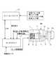
図1は請求項1〜4の発明に対応している実施の形態の制動制御装置の要部を示す構成説明図である。
図においてBRは制動装置を示している。この制動装置BRは、電動式のものであり、キャリパ筐体1の図中右端部に、一対の押圧部材としてのブレーキパッド2a,2bが左右に設けられ、このブレーキパッド2a,2bの間に図外の車輪と一体回転する回転部材としてのブレーキロータ3が配置され、両ブレーキパッド2a,2bによりブレーキロータ3を挟んで制動力を発生可能に構成されている。
【0013】
前記ブレーキパッド2a,2bの一方のブレーキパッド2aは、キャリパ筐体1に対して左右方向に移動可能に支持されているとともに、その背面にピストン41が設けられているとともに、ピストン4の背面に推力センサ5を介在させてピストンロッド4が設けられている。
このピストンロッド4は、キャリパ筐体1に対して図中左右方向に移動可能に支持されて、かつ、同軸に設けられた電動アクチュエータとしてのモータ6の回転が、減速機9を介して減速され、さらに回転−直線変換機構7により軸方向の変位に変換されて伝達されるよう構成されている。
なお、前記推力センサ5としては、ロードセルや圧電センサや半導体荷重センサや磁界式荷重センサなどを用いる。
さらに、前記モータ6には、このモータ6の回転量に基づいてブレーキパッド2aの位置を検出する位置検出装置8が設けられている。
【0014】
また、前記モータ6の駆動は、制御手段としてのモータドライバ11から出力されるモータ駆動電流により成される。
このモータドライバ11は、制御手段としてのメインコントローラ10から送られる要求推力と、前記推力センサ5から送られる推力センサ値(実推力)と、位置検出装置8から送られる位置検出値と、車輪速センサ25(図2参照)から送られる車輪速センサ値に基づいて、出力するモータ駆動電流を決定する構成となっている。なお、メインコントローラ10とモータドライバ11とは、CAN通信により繋がっている。
【0015】
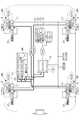
図2は、実施の形態の制動制御装置の全体図であって、この図に示すように、図1に示すモータ6およびモータドライバ11が各輪に設けられている。
また、メインコントローラ10には、車両の走行状態を検出するためにヨーレイトセンサ21,横加速度(以下、加速度をGと表記する)センサ22,前後Gセンサ23,舵角センサ24から検出値を入力するとともに、エンジンコントロールユニットECUからエンジンの駆動状態に関連する信号が、ATコントロールユニットACUから車輪の出力トルクに関連する信号が、アダプティブクルーズコントロールACCから信号が入力される。
さらに、メインコントローラ10には、運転者の制動操作を検出するために、ブレーキペダルBPのストローク量を検出する第1ストロークセンサ31および第2ストロークセンサ32と、ブレーキペダルBPに対する踏力を検出する踏力センサ33から信号が入力される構成となっている。
【0016】
次に、上記メインコントローラ10およびモータドライバ11により成される補正制御の流れについて図3および図4のフローチャートに基づき説明する。
最初のステップ301では、制動中であるか否か判断し、制動中であれば次のステップ302に進み、制動中でなければ最初に戻る。
次のステップ302では、あらかじめ設定された所定時間が経過したか否か判断し、所定時間が経過したら次のステップ303に進み、所定時間が経過していなければ最初に戻る。この所定時間は、ブレーキパッド2a,2bおよび推力センサ5の特性に基づいてブレーキパッド2a,2bの発熱により推力センサ5の出力値がシフトする制動時間に設定するもので、5,6秒〜10秒程度の時間に設定する。また、この所定時間は、車速に応じ、高速走行時は低速走行時に比べて短くするように可変としてもよい。
【0017】
次のステップ303では、車速があらかじめ設定された設定車速V1未満の低速であるか否か判断し、車速<V1の低速走行時にはステップ304に進んで、請求項4に記載の発明の第1の補正に相当する補正を実行し、車速≦V1の非低速走行時には図4のステップ400に進んで、請求項4に記載の発明の第2の補正に相当する補正を実行する。なお、設定車速V1は、本実施の形態の場合は20km/hとしているが、これに限られず、車両の特性に基づいて任意の速度に設定することができる。
【0018】
次にステップ304では、補正切替フラグiが=0であるか否か判断し、i=0の場合はステップ305に進み、i≠0(i=1)の場合はステップ310に進む。
ステップ305〜309では、対角に配置されている右前輪(FR)および左後輪(RL)に対する0点補正を実行する。
まず、ステップ305では、右前輪(FR)および左後輪(RL)に対する0点補正が終了したか否かを右前輪補正終了フラグf_FR_END=1かつ左後輪補正終了フラグf_RL_END=1であるか否かにより判断し、f_FR_END=1かつf_RL_END=1でない場合はステップ306に進み、f_FR_END=1かつf_RL_END=1の場合はステップ308に進む。
【0019】
ステップ306では、右前輪(FR)および左後輪(RL)の0点補正を実行し、続く、ステップ307において、この0点補正を実行していない対角輪である左前輪(FL)および右後輪(RR)の推力(制動力)を演算により求めた補正量だけ上昇させる。なお、このステップ307の処理が請求項3および請求項4に記載の発明の増大補正制御に相当する。
上記ステップ306における0点補正は、モータ6をあらかじめ設定された量だけブレーキパッド2aを後退させるだけ回転させ、このときの推力センサ5の出力値を「0」とする。すなわち、ブレーキパッド2aが確実にブレーキロータ3から離れてブレーキロータ3に対して推力が生じない状態となるだけモータ6を駆動させ、このときの推力センサ5の出力を「0」とするものであり、このときのモータ6の必要な駆動量はあらかじめ求めることができる。また、この0点補正を終了した時点で、右前輪補正終了フラグf_FR_ENDおよび左後輪補正終了フラグf_RL_ENDを、それぞれ=1にセットする。
また、ステップ307において求める推力上昇補正量は、そのとき検出されているヨーレイト、前後G、横Gおよび運転者の操作量に基づいて、総合的な制動力が低下しないように決定する。
【0020】
一方、上記ステップ306における補正処理を終了したら、次回のステップ305の判断においてYESと判断されてステップ308に進み、補正切替フラグiを反転(i=1)に変更する処理を実行し、さらに、ステップ309に進んで、右前輪補正終了フラグf_FR_ENDおよび左後輪補正終了フラグf_RL_ENDを、それぞれ=0にリセットする。よって、この次に、ステップ305の判断を行うときには、NOと判断されることになる。
【0021】
次に、ステップ304において、NOと判断されて進むステップ310〜314は、左前輪(FL)および右後輪(RR)の0点補正を行う部分である。
まず、ステップ310では、左前輪(FL)および右後輪(RR)に対する0点補正が終了したか否かを左前輪補正終了フラグf_FL_END=1かつ右後輪補正終了フラグf_RR_END=1であるか否かにより判断し、f_FL_END=1かつf_RR_END=1でない場合はステップ311に進み、f_FL_END=1かつf_RR_END=1の場合はステップ313に進む。
【0022】
ステップ311では、左前輪(FL)および右後輪(RR)の0点補正を実行し、続く、ステップ312において、この0点補正を実行していない対角輪である右前輪(FR)および左後輪(RL)の推力(制動力)を演算により求めた補正量だけ上昇させる(増大補正制御)。
上記ステップ311における0点補正も、上記ステップ306と同様にモータ6をあらかじめ設定された量だけ回転させて、このときの推力センサ5の出力値を「0」とする。
また、ステップ312で求める推力上昇補正量もステップ307と同様に、そのとき検出されているヨーレイト、前後G、横Gおよび運転者の操作量に基づいて総合的な制動力が低下しないように決定する。
【0023】
一方、上記ステップ311における補正処理を終了したら、次回のステップ310の判断においてYESと判断されてステップ313に進み、補正切替フラグi=0に戻す処理を実行し、さらに、ステップ314に進んで、左前輪補正終了フラグf_FL_ENDおよび右後輪補正終了フラグf_RR_ENDを、それぞれ=0にリセットする。
【0024】
以上のように、車速がV1(20km/h)未満の場合において0点補正を実行する場合は、対角に配置されている2輪の0点補正を実行するとともに、残りの対角の2輪に対してブレーキパッド2a,2bに対して与える推力、すなわち制動力を増加させる処理を実行する。
【0025】
次に、ステップ303において車速がV1以上の非低速走行時に進む、ステップ400以降の制御について図4に基づいて説明する。
ステップ401では、補正切替フラグjが=0であるか否か判断し、j=0の場合はステップ402に進み、j≠0の場合はステップ407に進む。
j=0の場合に進むステップ402〜406は、右前輪(FR)の0点補正を実行する。まず、ステップ402では、右前輪補正終了フラグf_FR_ENDが=1であるか(右前輪の0点補正が終了したか)否か判断し、f_FR_END≠1の場合はステップ403に進み、f_FR_END=1の場合はステップ405に進む。
【0026】
ステップ403では、右前輪(FR)の0点補正を実行するとともに、右前輪補正終了フラグf_FR_ENDを=1にセットする。なお、この0点補正処理自体は、ステップ306,311と同様であるので説明を省略する。
また、続くステップ404では、左前輪(FL)、右後輪(RR)、左後輪(RL)の推力を、補正量分だけ増加する処理(増大補正制御)を実行する。この補正量は、ステップ307,312と同様に、そのとき検出されているヨーレイト、前後G、横Gおよび運転者の操作量に基づいて総合的な制動力が低下しないように決定する。この場合、3輪で制動力を発生させるため、車両にヨーモーメントが発生しないように、右後輪(RR)における補正量を他の2輪に比べて大きくするのが好ましい。
また、ステップ403の補正処理を実行した場合、次回のステップ402の判断においてYESと判断されてステップ405に進み、補正切替フラグjを1だけ加算する(J=1とする)処理を実行し、続く、ステップ406において、右前輪補正終了フラグf_FR_ENDを0にリセットする。
【0027】
次に、ステップ401でNOと判断されて進むステップ407では、補正切替フラグj=1であるか否か判断し、j=1の場合はステップ408に進み、j≠1の場合にはステップ413に進む。
ステップ408〜412は、左前輪(FL)の0点補正処理を実行するものであり、まず、ステップ408では、左前輪補正終了フラグf_FL_ENDが=1であるか(左前輪の0点補正が終了したか)否か判断し、f_FL_END≠1の場合はステップ409に進み、f_FL_END=1の場合はステップ411に進む。
【0028】
ステップ409では、左前輪(FL)の0点補正を実行するとともに、左前輪補正終了フラグf_FL_ENDを=1にセットする。なお、この0点補正処理は、ステップ306,311と同様であるので説明を省略する。
また、続くステップ410では、右前輪(FR)、右後輪(RR)、左後輪(RL)の推力を、補正量分だけ増加する処理(増大補正制御)を実行する。この補正量は、ステップ307,312と同様に、そのとき検出されているヨーレイト、前後G、横Gおよび運転者の操作量に基づいて総合的な制動力が低下しないように決定する。
また、ステップ409の補正処理を実行した場合、次回のステップ408の判断においてYESと判断されてステップ411に進み、補正切替フラグjを1だけ加算する(J=2とする)処理を実行し、続く、ステップ412において、左前輪補正終了フラグf_FL_ENDを0にリセットする。
【0029】
次に、ステップ407でNOと判断されて進むステップ413では、補正切替フラグj=2であるか否か判断し、j=2の場合はステップ414に進み、j≠2の場合にはステップ419に進む。
ステップ414〜418は、右後輪(RR)の0点補正処理を実行するものであり、まず、ステップ414では、右後輪補正終了フラグf_RR_ENDが=1であるか(右後輪の0点補正が終了したか)否か判断し、f_RR_END≠1の場合はステップ415に進み、f_RR_END=1の場合はステップ417に進む。
【0030】
ステップ415では、右後輪(RR)の0点補正を実行するとともに、右後輪補正終了フラグf_RR_ENDを=1にセットする。なお、この0点補正処理は、ステップ306,311と同様であるので説明を省略する。
また、続くステップ416では、右前輪(FR)、左前輪(FL)、左後輪(RL)の推力を、補正量分だけ増加する処理(増大補正制御)を実行する。この補正量は、ステップ307,312と同様に、そのとき検出されているヨーレイト、前後G、横Gおよび運転者の操作量に基づいて総合的な制動力が低下しないように決定する。
また、ステップ415の補正処理を実行した場合、次回のステップ414の判断においてYESと判断されてステップ417に進み、補正切替フラグjを1だけ加算する(J=3とする)処理を実行し、続く、ステップ418において、右後輪補正終了フラグf_RR_ENDを0にリセットする。
【0031】
次に、ステップ413でNOと判断されて進むステップ419では、補正切替フラグj=3であるか否か判断し、j=3の場合はステップ420に進み、j≠3の場合には図3のステップ342に進む(最初に戻る)。
ステップ420〜424は、左後輪(RL)の0点補正処理を実行するものであり、まず、ステップ420では、左後輪補正終了フラグf_RL_ENDが=1であるか(左後輪の0点補正が終了したか)否か判断し、f_RL_END≠1の場合はステップ421に進み、f_RL_END=1の場合はステップ423に進む。
【0032】
ステップ421では、左後輪(RL)の0点補正を実行するとともに、左後輪補正終了フラグf_RL_ENDを=1にセットする。なお、この0点補正処理は、ステップ306,311と同様であるので説明を省略する。
また、続くステップ422では、右前輪(FR)、左前輪(FL)、右後輪(RR)の推力を、補正量分だけ増加する処理(増大補正制御)を実行する。この補正量は、ステップ307,312と同様に、そのとき検出されているヨーレイト、前後G、横Gおよび運転者の操作量に基づいて総合的な制動力が低下しないように決定する。
また、ステップ421の補正処理を実行した場合、次回のステップ420の判断においてYESと判断されてステップ423に進み、補正切替フラグj=0にリセットする処理を実行し、続く、ステップ424において、左後輪補正終了フラグf_RL_ENDを0にリセットする。
【0033】
以上のように、車速がV1(20km/h)以上の場合において0点補正を実行する場合は、1輪ずつ0点補正を実行するとともに、残りの3輪に対してブレーキパッド2a,2bに対して与える推力、すなわち制動力を増加させる処理を実行する。
【0034】
次に、実施の形態の制動制御装置における作動例について説明する。
長い下り坂などを走行して、運転者が制動操作を連続的に行った場合、ブレーキパッド2a,2bが発熱し、この熱が推力センサ5に伝達されて、その出力値がシフトする。
このような場合、本実施の形態にあっては、制動操作時間があらかじめ設定された所定時間を超えると、車速に応じて2通りの補正処理を実行する。
ここで、車速があらかじめ設定された設定値V1(例えば、20km/h)未満の場合、ステップ301→302→303→304→305→306の流れとなって、まず、右前輪(FR)および左後輪(RL)の0点補正を実行する。
この0点補正では、ブレーキパッド2aを確実にブレーキロータ3から離れるまで後退させて、そのときの出力値を「0点」として補正する。
この場合、この0点補正を実行する対角の2輪(右前輪、左後輪)においてごく短時間(例えば、50msec程度)ではあるが、制動力が無くなる。しかし、このとき、ステップ307の処理により、残りの対角の2輪における制動力を上昇させるものであり、制動力不足となることがないとともに、左右で制動力を均等として車両に不要なヨーモーメントが発生しないようにすることができる。
以上のように、0点補正を実施することにより、発熱による出力シフトの影響を受けることなく推力を正確に検出することができ、制御精度を向上させることができる。
【0035】
上述のように右前輪と左後輪の0点補正を行ったら、次回は、ステップ301→302→303→304→310→311の流れとなり、左前輪(FL)および右後輪(RR)の0点補正を行う。
この場合も、残りの2輪の制動力を上昇させるため、0点補正時に制動力不足となることがないとともに、短時間に補正を実行することができる。
【0036】
一方、車速が設定速度V1よりも高い場合には、ステップ301→302→303→400→401→402→403の流れとなって、右前輪(FR)の0点補正を実施するとともに、次のステップ404により残りの3輪の制動力を補正量だけ増加させる。
また、この0点補正を行ったら、次回は、401→407→408→409→410の流れとなって、左前輪(FL)の0点補正を実施するとともに、残りの3輪の制動力を補正する。
さらに、この0点補正を行ったら、次回は、401→407→413→414→415→416の流れとなって、右後輪の0点補正を行うとともに、残りの3輪の制動力を補正する。
さらに、この0点補正を行ったら、次回は、401→407→413→419→420→421→422の流れとなって、左後輪の0点補正を行うとともに、残りの3輪の制動力を補正する。
【0037】
このように、車速が設定車速V1よりも高いときには、1輪ずつ0点補正を行って、全体の制動力が低下しないようにしながら、0点補正を実行することができる。
【0038】
以上、本発明の実施の形態を図面により詳述してきたが、具体的な構成はこの実施の形態に限られるものではなく、本発明の要旨を逸脱しない範囲における設計の変更などがあっても本発明に含まれる。
例えば、制動装置BRなどの構成は、図示したものに限定されないものであり、要はブレーキパッドの近くに、推力センサ5が設けられている構成であれば、他の部分の構成、すなわち、モータ6や回転−直線変換機構7の配置や構成は実施の形態に示したものに限られない。また、電動アクチュエータとしてはモータ6以外の手段を用いてもよい。
【0039】
また、実施の形態では、車速により2輪補正(第1の補正)と1輪ずつの補正(第2の補正)とに分けて実行するようにしたが、これに限られず、常時、1輪ずつ補正あるいは2輪補正を行うようにしてもよい。
また、実施の形態では、補正制御を実行する態様として、運転者による制動状態が所定時間を超えたときとして説明したが、この所定時間を超えて成される制動状態とは、自動制動制御などによる制御による制動状態で実行する構成としてもよい。
【0040】
また、実施の形態では、補正を実行しない輪に対して制動力を増大させる増大補正制御を実行するようにした例を示したが、少なくとも、補正制御を実行していない輪に制動力を発生させていればよいものであり、通常の制御に対して制動力を増大させなくてもよい。
【0041】
また、補正制御は、要するに推力センサの出力に対して熱によるシフトを低減させる補正を実行するものであればよいものであり、0点補正以外にも、推力センサの特性に基づいてその出力に対して所定量の増加あるいは所定量の低下というような補正を行うようにしてもよい。
【図面の簡単な説明】
【図1】本発明実施の形態の制動制御装置を示す構成説明図である。
【図2】実施の形態の制動制御装置を示す全体図である。
【図3】実施の形態の制動制御装置の補正制御の流れを示すフローチャートである。
【図4】実施の形態の制動制御装置の補正制御の流れを示すフローチャートである。
【符号の説明】
BR ブレーキ装置
2a,2b ブレーキパッド(押圧部材)
3 ブレーキロータ(回転部材)
5 推力センサ
6 モータ
10 メインコントローラ(制御手段)
11 モータドライバ(制御手段)[0001]
BACKGROUND OF THE INVENTION
The present invention relates to an electric braking control device.
[0002]
[Background Art and Problems to be Solved by the Invention]
Conventionally, an electric braking control device that obtains a braking force by pressing and separating a friction material on a rotating body that rotates with a wheel by means of a motor is known from, for example, Japanese Patent Laid-Open No. 63-242766. It has been.
In such an electric braking control device, a brake force sensor that detects a force (braking force) that presses the friction material against the rotating body is provided, and the brake force detected thereby corresponds to, for example, a driver's pedal operation force. There is also known an apparatus configured to execute feedback control so as to coincide with the target braking force.
[0003]
However, since the brake force sensor is generally provided in the vicinity of the friction material, for example, when high heat is generated during braking, such as when traveling on a long downhill, it is affected by this heat. The sensor output value may shift.
When the sensor output value is shifted in this way, there is a problem that it is difficult to perform accurate feedback control.
The present invention has been made paying attention to such a problem, and an object of the present invention is to improve the control accuracy by correcting the shift of the sensor value due to heat.
[0004]
[Means for Solving the Problems]
In order to achieve the above object, the braking control device of the present invention provides a pressing member for a rotating member that rotates integrally with a wheel.Brake pad throughA braking device that generates a braking force by pressing, an electric actuator that is included in the braking device and applies thrust to the pressing member in a direction of pressing against the rotating member, a thrust sensor that detects the thrust by the electric actuator, A brake control means comprising: a control means for controlling the operation of the electric actuator based on an input of an input means including a thrust sensor;TravelingThe braking state isThe output value of the thrust sensor shifts due to heat generated by the brake pad.Over a given timeContinuouslyThe thrust sensor output to the remaining wheels in a state in which braking force is generated in a predetermined wheel of the four wheels.ShiftIt is a means characterized by executing correction control for correcting the above.
[0005]
According to a second aspect of the present invention, in the braking control device according to the first aspect,
The control means, during correction control, returns the pressing member to a state where no thrust is applied to the rotating member, and executes correction with the output of the thrust sensor at this time being zero. did.
[0006]
According to a third aspect of the present invention, in the braking control device according to the first or second aspect,
The control means is a means for executing an increase correction control for increasing a thrust with respect to an electric actuator of a wheel that generates a braking force during the correction control.
[0007]
The invention according to
In the correction control, the control means executes the first correction if the vehicle speed is less than the predetermined vehicle speed, and executes the second correction if the vehicle speed is higher than the predetermined vehicle speed.
In the first correction, first, correction control is executed for predetermined two wheels, and then correction control is executed for the remaining two wheels.
In the second correction, the correction control is executed sequentially for each wheel.
[0008]
Operation and effect of the invention
In the present invention, when the braking state is exceeded for a predetermined time and there is a high possibility that the output of the thrust sensor shifts due to the influence of heat, the control means executes correction control. During this correction control, the output of the thrust sensor is corrected for the remaining wheels in a state in which a braking force is generated in a predetermined wheel of the four wheels. As described above, there has been no correction that takes into account the shift of the sensor output due to heat during braking, but in the present invention, correction is performed so as to eliminate the influence of heat during braking. In addition to improving the accuracy, the correction is performed in a state in which the braking force is generated on a predetermined wheel. Therefore, even if the driver performs an operation to increase the braking force during the correction. Can respond to this without delayThe
[0009]
According to the second aspect of the present invention, during the correction control, the correction control means returns the pressing member to a state where no thrust is applied to the rotating member, and the output of the thrust sensor at this time is corrected to zero. Execute.
Therefore, the correction corresponding to the change of the zero point of the thrust sensor due to heat can be executed.
[0010]
In the invention according to
Therefore, although correction may be performed during braking, the braking force may be insufficient. However, by increasing the braking force of the remaining wheels, this can be prevented and the braking force can be shortened.
[0011]
In the invention according to
Therefore, the correction can be completed in a short time by performing the correction for each of the two wheels during low-speed traveling that does not require a large braking force.
In addition, during non-low-speed traveling that requires a large braking force, it is possible to prevent the braking force from being insufficient by correcting one wheel at a time.
[0012]
DETAILED DESCRIPTION OF THE INVENTION
Hereinafter, a braking control device according to an embodiment of the present invention will be described.
FIG. 1 is a structural explanatory view showing a main part of a braking control apparatus according to an embodiment corresponding to the first to fourth aspects of the present invention.
In the figure, BR indicates a braking device. The braking device BR is an electric type, and
[0013]
One
The
As the
Further, the
[0014]
The
The
[0015]
FIG. 2 is an overall view of the braking control apparatus according to the embodiment. As shown in this figure, the
Further, the
Further, the
[0016]
Next, the flow of correction control performed by the
In the
In the
[0017]
In the
[0018]
Next, in
In
First, in
[0019]
In
In the zero point correction in
Further, the thrust increase correction amount obtained in
[0020]
On the other hand, when the correction process in
[0021]
Next, in
First, at
[0022]
In
In the zero point correction in
Also, the thrust increase correction amount obtained in
[0023]
On the other hand, when the correction process in
[0024]
As described above, when the zero point correction is executed when the vehicle speed is less than V1 (20 km / h), the zero point correction of the two wheels arranged diagonally is executed and the remaining diagonal 2 A process of increasing the thrust applied to the
[0025]
Next, the control after
In
[0026]
In
In the
In addition, when the correction process of
[0027]
Next, in
[0028]
In
In the
Further, when the correction process of
[0029]
Next, in
[0030]
In
In the
When the correction process of
[0031]
Next, in
[0032]
In
In the
In addition, when the correction process of
[0033]
As described above, when the zero point correction is executed when the vehicle speed is V1 (20 km / h) or more, the zero point correction is executed for each wheel and the
[0034]
Next, an operation example in the braking control device of the embodiment will be described.
When the driver travels on a long downhill or the like and continuously performs the braking operation, the
In such a case, in this embodiment, when the braking operation time exceeds a predetermined time set in advance, two types of correction processing are executed according to the vehicle speed.
Here, when the vehicle speed is less than a preset set value V1 (for example, 20 km / h), the flow is
In this zero point correction, the
In this case, the braking force is lost in the two diagonal wheels (right front wheel and left rear wheel) on which the zero point correction is performed, although for a very short time (for example, about 50 msec). However, at this time, the processing in
As described above, by performing the zero point correction, the thrust can be accurately detected without being affected by the output shift due to heat generation, and the control accuracy can be improved.
[0035]
If the zero-point correction of the right front wheel and the left rear wheel is performed as described above, the next step is the flow of
Also in this case, since the braking force of the remaining two wheels is increased, the braking force does not become insufficient during the zero point correction, and the correction can be executed in a short time.
[0036]
On the other hand, when the vehicle speed is higher than the set speed V1, the flow of
When this zero point correction is performed, the next time, the flow is 401 → 407 → 408 → 409 → 410, the zero point correction of the left front wheel (FL) is performed, and the braking force of the remaining three wheels is increased. to correct.
Furthermore, if this zero point correction is performed, next time, the flow will be 401 → 407 → 413 → 414 → 415 → 416, and the right rear wheel will be corrected to the zero point and the braking power of the remaining three wheels will be corrected. To do.
Furthermore, if this zero point correction is performed, next time, the flow will be 401 → 407 → 413 → 419 → 420 → 421 → 422, the zero point correction of the left rear wheel is performed, and the braking force of the remaining three wheels is corrected. Correct.
[0037]
Thus, when the vehicle speed is higher than the set vehicle speed V1, the zero point correction can be performed while performing zero point correction for each wheel so that the overall braking force does not decrease.
[0038]
The embodiment of the present invention has been described in detail with reference to the drawings, but the specific configuration is not limited to this embodiment, and even if there is a design change without departing from the gist of the present invention. It is included in the present invention.
For example, the configuration of the braking device BR or the like is not limited to that shown in the figure. In short, as long as the
[0039]
In the embodiment, the two-wheel correction (first correction) and the one-wheel correction (second correction) are executed separately according to the vehicle speed. However, the present invention is not limited to this. Correction or two-wheel correction may be performed one by one.
Further, in the embodiment, the correction control is described as a mode in which the braking state by the driver exceeds a predetermined time. However, the braking state that exceeds the predetermined time is an automatic braking control or the like. It is good also as a structure performed in the braking state by control by.
[0040]
Further, in the embodiment, the example in which the increase correction control for increasing the braking force is performed on the wheel that is not subjected to the correction has been described, but at least the braking force is generated on the wheel that is not performing the correction control. It is sufficient that the braking force is increased as compared with the normal control.
[0041]
In addition, the correction control only needs to execute correction for reducing the shift due to heat with respect to the output of the thrust sensor. In addition to the zero point correction, the correction control is performed based on the characteristics of the thrust sensor. On the other hand, correction such as increase of a predetermined amount or decrease of the predetermined amount may be performed.
[Brief description of the drawings]
FIG. 1 is an explanatory diagram showing a configuration of a braking control device according to an embodiment of the present invention.
FIG. 2 is an overall view showing a braking control device of the embodiment.
FIG. 3 is a flowchart showing a flow of correction control of the braking control apparatus of the embodiment.
FIG. 4 is a flowchart showing a flow of correction control of the braking control device of the embodiment.
[Explanation of symbols]
BR brake device
2a, 2b Brake pad (pressing member)
3 Brake rotor (rotating member)
5 Thrust sensor
6 Motor
10 Main controller (control means)
11 Motor driver (control means)
Claims (4)
Translated fromJapanese前記制御手段は、走行中の制動状態が前記ブレーキパッドの発熱により前記推力センサの出力値がシフトする所定時間を超えて連続的に成されたときに、4輪のうちの所定の輪に制動力を発生させた状態で、残りの輪に対して前記推力センサの出力のシフトを補正する補正制御を実行することを特徴とする制動制御装置。A braking device that generates a braking force by pressinga brake pad against a rotating member that rotates integrally with a wheelvia a pressing member, and a thrust that is included in the braking device and that presses the rotating member against the rotating member A braking control means comprising: an electric actuator that provides a thrust; a thrust sensor that detects the thrust by the electric actuator; and a control means that controls the operation of the electric actuator based on an input of an input means including the thrust sensor. ,
The control means controlsa predetermined one of the four wheels when therunning braking state iscontinuously performed overa predetermined time during whichthe output value of the thrust sensor shifts due to heat generated by the brake pad. A braking control device that performs correction control for correcting ashift in the outputof the thrust sensor with respect to the remaining wheels in a state where power is generated.
Priority Applications (1)
| Application Number | Priority Date | Filing Date | Title |
|---|---|---|---|
| JP2002009039AJP3842654B2 (en) | 2002-01-17 | 2002-01-17 | Braking control device |
Applications Claiming Priority (1)
| Application Number | Priority Date | Filing Date | Title |
|---|---|---|---|
| JP2002009039AJP3842654B2 (en) | 2002-01-17 | 2002-01-17 | Braking control device |
Publications (2)
| Publication Number | Publication Date |
|---|---|
| JP2003205837A JP2003205837A (en) | 2003-07-22 |
| JP3842654B2true JP3842654B2 (en) | 2006-11-08 |
Family
ID=27647143
Family Applications (1)
| Application Number | Title | Priority Date | Filing Date |
|---|---|---|---|
| JP2002009039AExpired - Fee RelatedJP3842654B2 (en) | 2002-01-17 | 2002-01-17 | Braking control device |
Country Status (1)
| Country | Link |
|---|---|
| JP (1) | JP3842654B2 (en) |
Families Citing this family (5)
| Publication number | Priority date | Publication date | Assignee | Title |
|---|---|---|---|---|
| JP4160465B2 (en)* | 2003-08-26 | 2008-10-01 | 本田技研工業株式会社 | Braking device |
| JP5929792B2 (en)* | 2013-03-15 | 2016-06-08 | 株式会社アドヴィックス | Electric braking device for vehicle |
| JP5849978B2 (en)* | 2013-03-15 | 2016-02-03 | 株式会社アドヴィックス | Electric braking device for vehicle |
| US9505385B2 (en) | 2013-03-15 | 2016-11-29 | Advics Co., Ltd. | Electric braking system for vehicle |
| JP2018121461A (en) | 2017-01-26 | 2018-08-02 | Ntn株式会社 | Motor-driven direct-acting actuator and electric brake device |
- 2002
- 2002-01-17JPJP2002009039Apatent/JP3842654B2/ennot_activeExpired - Fee Related
Also Published As
| Publication number | Publication date |
|---|---|
| JP2003205837A (en) | 2003-07-22 |
Similar Documents
| Publication | Publication Date | Title |
|---|---|---|
| EP3050765B1 (en) | Control device for electric vehicle | |
| JP4519439B2 (en) | Vehicle behavior detection device and vehicle behavior control device using vehicle behavior detection device | |
| WO2013085000A1 (en) | Electric vehicle control device | |
| JP5554843B2 (en) | Method for reducing steering torque during brake operation | |
| WO2019102998A1 (en) | Vehicle | |
| WO2021166596A1 (en) | Vehicle control device, vehicle control method, and vehicle control system | |
| JP5120297B2 (en) | Electric vehicle regenerative braking control device | |
| JP3817923B2 (en) | Steering control device | |
| JP2013180670A (en) | Braking force control device | |
| JP3842654B2 (en) | Braking control device | |
| JP6453103B2 (en) | Vehicle motion control device | |
| JP5173330B2 (en) | Vehicle travel control device | |
| JP2016215864A (en) | Electric power steering apparatus | |
| JP5685088B2 (en) | Braking device for vehicle | |
| JP6399007B2 (en) | Vehicle driving support device | |
| JP5251319B2 (en) | Electric brake device | |
| JP7234586B2 (en) | Driving force control device, driving device, and driving force transmission device | |
| JP2008094214A (en) | Vehicle motion control device | |
| JP7583596B2 (en) | Vehicle control device | |
| WO2020179267A1 (en) | Drive control device | |
| JP2011051535A (en) | Electric brake device | |
| JP5574108B2 (en) | Regenerative braking control device | |
| JP3577226B2 (en) | Steering control device | |
| JP2003220943A (en) | Braking control device | |
| JP5082403B2 (en) | Steering angle control device for vehicle |
Legal Events
| Date | Code | Title | Description |
|---|---|---|---|
| A621 | Written request for application examination | Free format text:JAPANESE INTERMEDIATE CODE: A621 Effective date:20040817 | |
| A711 | Notification of change in applicant | Free format text:JAPANESE INTERMEDIATE CODE: A712 Effective date:20041217 | |
| RD04 | Notification of resignation of power of attorney | Free format text:JAPANESE INTERMEDIATE CODE: A7424 Effective date:20060120 | |
| A977 | Report on retrieval | Free format text:JAPANESE INTERMEDIATE CODE: A971007 Effective date:20060223 | |
| A131 | Notification of reasons for refusal | Free format text:JAPANESE INTERMEDIATE CODE: A131 Effective date:20060307 | |
| A521 | Written amendment | Free format text:JAPANESE INTERMEDIATE CODE: A523 Effective date:20060426 | |
| TRDD | Decision of grant or rejection written | ||
| A01 | Written decision to grant a patent or to grant a registration (utility model) | Free format text:JAPANESE INTERMEDIATE CODE: A01 Effective date:20060808 | |
| A61 | First payment of annual fees (during grant procedure) | Free format text:JAPANESE INTERMEDIATE CODE: A61 Effective date:20060810 | |
| R150 | Certificate of patent (=grant) or registration of utility model | Free format text:JAPANESE INTERMEDIATE CODE: R150 | |
| LAPS | Cancellation because of no payment of annual fees |