JP3842308B2 - Stereoscopic microscope and operation method thereof - Google Patents
Stereoscopic microscope and operation method thereofDownload PDFInfo
- Publication number
- JP3842308B2 JP3842308B2JP02680095AJP2680095AJP3842308B2JP 3842308 B2JP3842308 B2JP 3842308B2JP 02680095 AJP02680095 AJP 02680095AJP 2680095 AJP2680095 AJP 2680095AJP 3842308 B2JP3842308 B2JP 3842308B2
- Authority
- JP
- Japan
- Prior art keywords
- stereoscopic
- stereoscopic microscope
- focal length
- main objective
- optical
- Prior art date
- Legal status (The legal status is an assumption and is not a legal conclusion. Google has not performed a legal analysis and makes no representation as to the accuracy of the status listed.)
- Expired - Lifetime
Links
- 238000000034methodMethods0.000titleclaimsdescription8
- 230000003287optical effectEffects0.000claimsdescription96
- 239000007787solidSubstances0.000claimsdescription21
- 230000000007visual effectEffects0.000claimsdescription7
- 230000010354integrationEffects0.000claims1
- 230000008878couplingEffects0.000description6
- 238000010168coupling processMethods0.000description6
- 238000005859coupling reactionMethods0.000description6
- 230000001419dependent effectEffects0.000description2
- 238000010586diagramMethods0.000description2
- 230000001360synchronised effectEffects0.000description2
- 230000005540biological transmissionEffects0.000description1
- 238000005516engineering processMethods0.000description1
- 238000011156evaluationMethods0.000description1
- 238000005286illuminationMethods0.000description1
- 238000001356surgical procedureMethods0.000description1
Images

Classifications
- G—PHYSICS
- G02—OPTICS
- G02B—OPTICAL ELEMENTS, SYSTEMS OR APPARATUS
- G02B7/00—Mountings, adjusting means, or light-tight connections, for optical elements
- G02B7/02—Mountings, adjusting means, or light-tight connections, for optical elements for lenses
- G02B7/12—Adjusting pupillary distance of binocular pairs
- G—PHYSICS
- G02—OPTICS
- G02B—OPTICAL ELEMENTS, SYSTEMS OR APPARATUS
- G02B21/00—Microscopes
- G02B21/18—Arrangements with more than one light path, e.g. for comparing two specimens
- G02B21/20—Binocular arrangements
- G02B21/22—Stereoscopic arrangements
- A—HUMAN NECESSITIES
- A61—MEDICAL OR VETERINARY SCIENCE; HYGIENE
- A61B—DIAGNOSIS; SURGERY; IDENTIFICATION
- A61B90/00—Instruments, implements or accessories specially adapted for surgery or diagnosis and not covered by any of the groups A61B1/00 - A61B50/00, e.g. for luxation treatment or for protecting wound edges
- A61B90/20—Surgical microscopes characterised by non-optical aspects
Landscapes
- Physics & Mathematics (AREA)
- General Physics & Mathematics (AREA)
- Optics & Photonics (AREA)
- Chemical & Material Sciences (AREA)
- Analytical Chemistry (AREA)
- Microscoopes, Condenser (AREA)
Description
Translated fromJapanese【0001】
【産業上の利用分野】
調節可能なバック焦点距離の主対物レンズを有し、主対物レンズのバック焦点距離が変化した場合でも不変の生理学的視覚印象が存在する立体視顕微鏡に関する。
【0002】
【従来の技術】
ドイツ国実用新案G9003458.9号から、手術用顕微鏡の調節可能なバック焦点距離の主対物レンズは公知である。この主対物レンズは、主として相互移動可能な2つのレンズ群からなり、その際そのつどの相対的移動に依存して、主対物レンズの物体側の焦点距離が変化しうる。しかし、このような焦点距離の変化は、なかんずく立体角の変化を生じる。
【0003】
手術用顕微鏡の光学的性能に対する要求の増加につれて、主対物レンズの調節されたバック焦点距離に依存して変化する立体角およびそれにより変化する生理学的視覚印象は外科医にとって不利であることが判明した。
【0004】
【発明が解決しようとする課題】
従って、本発明の課題は、上述した先行技術の欠点を回避する立体視顕微鏡を提供することである。主対物レンズの物体側の焦点距離が変化する場合でも、立体視顕微鏡における生理学的視覚印象は不変であるように努力される。
【0005】
【課題を解決するための手段】
この課題は、調節可能なバック焦点距離の主対物レンズと第1の部分の立体視鏡光路および第2の部分の立体視鏡光路の光軸の調節可能な横方向移動とを有する立体視顕微鏡の場合に、主対物レンズのバック焦点距離と第1の部分の立体視鏡光路および第2の部分の立体視鏡光路の光軸の横方向移動とが連動するという請求項1の特徴を有する立体視顕微鏡によって解決され、また、
倍率交換レンズを備えた立体視顕微鏡の場合に、調節可能なバック焦点距離の主対物レンズと倍率交換レンズとが、実際の調節の際に、バック焦点距離の調節とは独立に、観察者により選択可能な、立体視顕微鏡の光学系の一定の全倍率が生じるように連動しているという請求項15の特徴を有する、倍率交換レンズを備えた立体視顕微鏡によって解決される。
【0006】
本発明による立体視顕微鏡の有利な構成は、請求項2から14までのいずれか1項の従属請求項ならびに請求項16から19までのいずれか1項の従属請求項に存在する。本発明による立体視顕微鏡の適当な操作方法は、請求項20から22までのいずれか1項の対象である。
【0007】
主対物レンズのバック焦点距離の調節と主対物レンズ後方の立体視鏡の部分的光路長との間の本発明による連動に基づき、主対物レンズの物体側の焦点距離が変化した場合でも、観察者には常に一定の立体角が存在することが保証されている。
【0008】
本発明による連動には、所望の精度および費用によって一連の実現可能性が存在する。
【0009】
調節可能なバック焦点距離の主対物レンズの場合、バック焦点距離に依存する立体角と共に、立体視顕微鏡の全光学系の倍率は、なかんずく主対物レンズのそのつどの物体側の焦点距離にも依存することから、所望の一定の生理学的視覚印象の妨害が生じる。それにより、このバック焦点距離が変化する場合に、立体視顕微鏡の全倍率も一定にとどまらず、特定の範囲内で変化する。従って、本発明によれば主対物レンズの検知された物体側の焦点距離は、立体角を一定に保つために利用されないで、倍率交換レンズを有する立体視顕微鏡において立体視顕微鏡の全倍率を一定に保つための入力量としても使用される。それにより、別の第2の連動により、調節可能なバック焦点距離の主対物レンズの後に接続された倍率交換レンズの固有倍率はバック焦点距離に依存して制御または調節される。
【0010】
それにより全体として、観察者に対して、主対物レンズの調節された対物側の焦点距離とは独立に、立体視顕微鏡において一定の生理学的視覚印象が生じる。従って、殊に本発明による立体視顕微鏡の手術用顕微鏡としての使用に対して一連の利点が生じる。
【0011】
有利には本発明による連動は、適当な操作部材を介して選択的に遮断および接続することができるので、観察者は本発明による立体視顕微鏡の種々の操作モードの間で選択自由度を有する。
【0012】
本発明による立体視顕微鏡の別の利点および詳細は、添付図面による実施例の下記の記載から明らかである。
【0013】
【実施例】
図1には、本発明による立体視顕微鏡の第1の実施例が示されている。本発明による立体視顕微鏡は、2つの別個のレンズ部材(1a,1b)からなる、調節可能なバック焦点距離を有する主対物レンズ(1)を備えている。前面に配置された負のレンズ部材(1a)は、立体視顕微鏡のケーシング内に堅固に配置され、正のレンズ部材(1b)は光軸(14)に沿って限定されて移動可能である。調節可能なバック焦点距離を有し、他の点では、上記のドイツ国実用新案G9003458.9号に一致する主対物レンズ(1)を用いると、150mm〜450mmの範囲内の焦点距離の物体側の変化が可能である。観察者側で、立体視鏡の部分光路内に配置された光学部材(2a,2b)が続き、該部材を用いて立体視鏡の部分光路を、主対物レンズ(1)と後方に配置された倍率交換レンズ(4a,5a,6a/4b,5b,6b)の間で制限されて横方向に移動することができる。この場合、本発明による立体視顕微鏡の図示された実施例においては、倍率交換レンズ(104a,105a,106a;104b,105b,106b)は、無条件に必要ではないことを指摘する。
【0014】
双方の光学部材(2a,2b)は、それぞれ立体視鏡の部分光路の光軸(15a,15b)に対して直角に配向された軸(3a,3b)のまわりで回転しうる、互いに同期化された立方体プリズムとして構成されている。立方体プリズムは、伝動装置を介してそれぞれ他の軸(3a,3b)上に配置されたギヤに係合するので、立方体プリズムが傾斜した場合、他の立体視鏡の部分光路中で立方体プリズムが同じ角度だけ相応して反対方向に同期的に傾斜する。それと共に、双方の立体視鏡の部分光路の光軸(15a,15b)は、それぞれ同じ大きさだけ内側または外側へ平行移動する。このような装置の可能な機械的構成のためには本出願人のドイツ国実用新案(G9305447.5号)が指摘され、そこにはこの装置を用いて立体視鏡の組み合わされた選択的調節が実現されている、主対物レンズのバック焦点距離との連動は設けられていない。
【0015】
双方の回転可能の光学部材(2a,2b)に、立体視鏡の部分光路中に配置された公知の倍率交換レンズの光学部材(4a,5a,6a/4b,5b,6b)が続く。倍率交換レンズの1つまたは幾つかの光学部材(4a,5a,6a/4b,5b,6b)を相互にずらすことによって、利用者により所望の倍率を明確に調節することができる。図示のステップレス倍率交換レンズの代りに、離散倍率ステップを有する公知のガリレイ変換器を倍率交換レンズとして使用することもできる。さらに、本発明による立体視顕微鏡の簡単な構成において、倍率交換レンズ(104a,105a,106a;104b,105b,106b)を断念することも可能である。
【0016】
図示された実施例においては、倍率交換レンズ(4a,5a,6a/4b,5b,6b)に、観察側で立体視像の部分光路中に、像正立プリズム(7a,7b)ならびにビューレンズまたは接眼レンズ(8a,9a/8b,9b)が続き、これらは公知の形式に配置される。
【0017】
さらに、立体視顕微鏡は、少なくとも1つの光源ならびに1つまたは幾つかの転向部材を有する照明装置(図示せず)を有する。
【0018】
ところで、本発明によれば、主対物レンズ(1)の物体側の焦点距離の調節と観察者用の立方体プリズムの傾斜との間の連動によって一定の立体角δsが実現される。さらに、本発明により一定に保たれる立体角δsは双方の立方体プリズムにより予め選択可能である。手術前に、手術する外科医は、要件により、図示されてない操作部材を介して所望の立体角δsに調節する。一度調節した立体角δsを一定に保つために、双方の立方体プリズムを、主対物レンズ(1)のバック焦点距離に依存して適当に傾けることによって、立体視鏡の部分光路の双方の光軸(15a,15b)間の距離Scは、この距離Scが主対物レンズ(1)の直接後方で変化し、それと共に立体角δsが実際に主対物レンズのバック焦点距離に依存して変化するときでも、一定に保たれる。従って、観察者には本発明による連動装置に基づき、そのつどの主対物レンズのバック焦点距離とは独立に、常に一定の立体角δsが生じる。
【0019】
バック焦点距離の変化の際に距離Scが大きくなるか小さくなるかにより、この場合に生じるこの距離の変化δscは、双方の立方体プリズムを相応に反対方向に傾けることによって、双方の立体視鏡の部分光路の光軸が常に同じ一定距離Scを有するように補償しなければならない。
【0020】
図1の実施例において、観察者に対し一定の立体角δsを保証するために、主対物レンズ(1)のバック焦点距離の調節と、双方の立体視鏡の部分光路の光軸(15a,15b)の平行移動とが機械的に連動されている。このために、調節可能なバック焦点距離の主対物レンズ(1)の移動可能のレンズ部材(1b)が結合部材(10)を介してスピンドル駆動軸(11)と結合していて、該駆動軸がこのレンズ部材(1b)の光軸(14)に沿った運動が、後方に配置された光学部材(2a,2b)の、立体視鏡の部分光路中で相応する旋回軸(3a,3b)を中心とする傾斜と連動している。この場合、双方の光学部材の少なくとも1つ(2b)は、もう1つの結合部材(12)を介して同様にスピンドル駆動軸(11)と結合している。結合は、主対物レンズ(1)のそのつどのバック焦点距離とは独立に一定の立体角δsが存在するように意図されている。従って、立方体プリズムの傾倒は、主対物レンズ(1)の可動レンズ部材(1b)の直線移動と同調するようでなければならない。場合によっては、このために立方体プリズムとスピンドル駆動軸(11)の間の結合部材(12)に適当な移動カム曲線を寸法定めすることもできる。
【0021】
主対物レンズのバック焦点距離の調節は、図示された実施例においては手動で、スピンドル駆動軸(11)を介して行なわれるかまたは可動レンズ部材(1b)と結合している操作部材(13)を介して行なわれる。しかしその代りに、適当な駆動装置を介してこのレンズ部材(1b)のモータによる移動調整および双方の立方体プリズムのモータによる相応する移動調整も常に可能である。
【0022】
もちろん、図1に略示された、主対物レンズのバック焦点距離と立体角δsとの間の機械的連動は、構造上、選択可能であるように実現することもできる。この場合、本発明によれば、連動により、物体側の主対物レンズの焦点距離の変化の際にも立体角δsの不変性が保証されていることは、重要なことである。
【0023】
本発明による立体視顕微鏡のもう1つの実施例は、図2における略図につき記載する。この場合、本発明による立体視顕微鏡のこの実施例の光学系は、大体において図1からの実施例の光学系に一致する。従って、図示された立体視顕微鏡の光学系は、同様に、定置の負のレンズ部材(100a)およびこれに対して可動の正のレンズ部材(100b)からなる、調節可能なバック焦点距離の主対物レンズ(100)を備えている。その後方に、立方体プリズムとして構成された2つの光学部材(102a,102b)が続き、これらはそれぞれ再び、双方の立体視鏡の部分光路の光軸(125a,125b)に対して直角に整列されている軸(103a,103b)のまわりで反対方向に同期的に回転可能である。前記の2つの光学部材には、調節された倍率のステップレス変化を可能にする倍率交換レンズ(104a,105a,106a/104b,105b,106b)が続く。このために、公知のパンクラテイックの倍率交換レンズが設けられている。さらに、立体視鏡の部分光路中に、正立プリズム(107a,107b)ならびにビューレンズまたは接眼レンズ(108a,109a/108b,109b)が公知形式で配置されている。
【0024】
図1からの図示された実施例とは、本発明による立体視顕微鏡のこの実施例は一方で、主対物レンズ(100)の可動のレンズ部材(100b)の移動調整が今やモータ駆動装置(110)によって行なわれることにより区別される。この場合、光軸(140)上での可動のレンズ部材(100b)のそのつどの位置は、所属するエンコーダ(111)によって検知される。それで、そのつど調節された主対物レンズのバック焦点距離は常に知られている。モータ駆動装置(110)の制御も、エンコーダ(111)により供給される位置情報の評価も、中央サーボコントロール装置(120)が引き受ける。
【0025】
光軸(140)上での可動のレンズ部材(100b)のそのつどの位置、つまり実際に調節された主対物レンズ(100)の物体側の焦点距離に対する評価されたエンコーダ情報に応じて、もう1つのモータ駆動装置(112)によって、立体角δsを一定に保つために必要な、立方体プリズムとして構成された双方の光学部材(102a,102b)が連動して傾倒する。
【0026】
この傾倒は再び、スピンドル駆動軸(116)およびそれと結合している、モータ駆動装置(112)および双方の光学部材のいずれか(103b)を相互に結合するレバーバー(117)を介して行なわれる。双方の光学部材(102a,102b)の実際の角度調整およびそれと共にこれにより惹起される、立体視鏡の部分光路の光軸(125a,125b)の平行移動は、図示の実施例では同様に所属するエンコーダ(113)により検知される。
【0027】
それで、中央のサーボコントロール装置(120)を介して、主対物レンズ(100)のバック焦点距離の調節と立体視鏡の部分光路の移動との間のサーボコントロールされる連動は、立体視鏡の部分光路の光軸(125a,125b)の距離Scが実際に変化する場合でも、主対物レンズ(100)の直接後方で観察者に対し常に不変の立体角δsが生じるように保証している。
【0028】
この場合、サーボコントロールされる連動は、所望の費用により、制御または調整回路として構成することができる。図2に図示された実施例におけるような変更調整回路においてサーボコントロール装置(120)が連続的に、双方の立方体プリズムの実際の傾倒および生じる平行移動を検知するが、変更制御回路においてはこのような帰還はなくすことができる。サーボ制御される連動のこのような構成は、調整技術の投入により、所要経費が相応に僅かである。
【0029】
検知された、主対物レンズ(100)の実際のバック焦点距離に関する情報は、図2に示された実施例においては、サーボ制御装置(120)を介して、もはやたんに双方の光学部材(102a,102b)の角度調節および立体角δsの一定保持と結合するために使用されるだけでなく、さらに本発明による立体視顕微鏡の光学系の一定の全倍率を調節するための入力量として利用される。このために、倍率交換レンズの光学部材(104a,105a,106a/104b,105b,106b)の1つまたは幾つかは同様にモータ駆動装置(114)と結合していて、該モータ駆動装置が光軸に沿った相応する移動調整、それと共に倍率の定義された調節を可能にする。この駆動装置(114)に所属するエンコーダ(115)は、倍率交換レンズ(104a,105a,106a/104b,105b,106b)のそのつどの倍率を連続的に検知する。
【0030】
エンコーダの全情報は同じく中央のサーボ制御装置(120)により検知され、相応に評価される。
【0031】
本発明による立体視顕微鏡のこの実施例においても、再び主対物レンズ(100)の実際のバック焦点距離に依存して、立体視顕微鏡の観察者に重要な別の倍率、即ち全倍率の調節を制御または調整する、別の第2の連動が実現される。相応する制御または調整回路により、立体視顕微鏡の光学系の一定の全倍率を達成しようと努力される。本発明による立体視顕微鏡の所望の全倍率は、たとえば立体視顕微鏡に配置された(図示されてない)調節部材により、利用者によって選択可能である。そのつど選択された全倍率は、さきに記載したように、手術の経過中一定に保たれる。
【0032】
最後に記載した、そのつどの主対物レンズのバック焦点距離と立体視顕微鏡の光学系の全倍率との間の結合は、立体視顕微鏡において一定の立体角を実現するための記載した第1の連動とは独立に使用することもできる。たんに、主対物レンズのバック焦点距離の検知および全倍率との連動が必要である。
【0033】
図2に記載したサーボコントロールされる連動と共に、この連動をカム駆動装置等による機械的変形として実現することもできる。
【0034】
さらに、記載されたすべての連動を、適当な操作部材を用い観察者により選択的に接続および遮断して、本発明による立体視顕微鏡に対する一連の可能な操作モードが生じるようにすることは、有利であることが判明した。
【図面の簡単な説明】
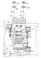
【図1】 第1実施例の本発明による立体視顕微鏡の概略図
【図2】 付加的に主対物レンズのバック焦点距離と倍率交換装置との間の結合が設けられている、第2実施例の本発明による立体視顕微鏡の概略図
【符号の説明】
1 主対物レンズ
1a,1b レンズ部材
2a,2b 光学部材
3a,3b 旋回軸
4a,5a,6a 倍率交換レンズ
4b,5b,6b 倍率交換レンズ
7a,7b 正立プリズム
8a,9a/8b,9b 接眼レンズ
10 結合部材
11 スピンドル駆動軸
12 結合部材
13 操作部材
100 主対物レンズ
100a 負のレンズ部材
100b 正のレンズ部材
102a,102b 立方体プリズム
103a,103b 軸
104a,105a,106a 倍率交換レンズ
104b,105b,106b 倍率交換レンズ
107a,107b 正立レンズ
108a,109a/108b,109b 接眼レンズ
110 モータ駆動装置
111 エンコーダ
112 モータ駆動装置
113 エンコーダ
114 モータ駆動装置
115 エンコーダ
116 スピンドル駆動軸
117 レバーバー
120 サーボコントロール装置
125a,125b 光軸
140 光軸[0001]
[Industrial application fields]
The present invention relates to a stereoscopic microscope having a main objective lens with an adjustable back focal length, and having a physiological visual impression that does not change even when the back focal length of the main objective lens changes.
[0002]
[Prior art]
A main objective lens with adjustable back focal length of a surgical microscope is known from German utility model G90038.9. This main objective lens mainly comprises two lens groups that can move relative to each other, and the focal length on the object side of the main objective lens can change depending on the relative movement of each lens group. However, such a change in focal length causes a change in solid angle, among others.
[0003]
As the demands on the optical performance of surgical microscopes increase, the solid angle that changes depending on the adjusted back focal length of the main objective and the resulting physiological visual impression has proved disadvantageous for the surgeon. .
[0004]
[Problems to be solved by the invention]
Accordingly, an object of the present invention is to provide a stereoscopic microscope that avoids the disadvantages of the prior art described above. Even when the focal length on the object side of the main objective lens changes, the physiological visual impression in the stereoscopic microscope is tried to remain unchanged.
[0005]
[Means for Solving the Problems]
The object is to provide a stereoscopic microscope with an adjustable back focal length main objective lens and an adjustable lateral movement of the optical axis of the first part of the stereoscopic optical path and of the second part of the stereoscopic optical path. In this case, the back focal length of the main objective lens and the lateral movement of the optical axis of the stereoscopic optical path of the first part and the stereoscopic optical path of the second part are interlocked with each other. Solved by a stereoscopic microscope,
In the case of a stereoscopic microscope equipped with an interchangeable magnification lens, the main objective lens with adjustable back focal length and the interchangeable magnification lens can be adjusted by the observer independently of the adjustment of the back focal length during the actual adjustment. This is solved by a stereoscopic microscope having a magnification interchangeable lens having the feature of claim 15, which is interlocked to produce a selectable, full magnification of the optical system of the stereoscopic microscope.
[0006]
Advantageous configurations of the stereoscopic microscope according to the invention lie in the dependent claims of claims 2 to 14 and the dependent claims of claims 16 to 19. A suitable method for operating a stereoscopic microscope according to the invention is the subject of any one of claims 20-22.
[0007]
Even if the focal length on the object side of the main objective lens changes based on the linkage according to the present invention between the adjustment of the back focal length of the main objective lens and the partial optical path length of the stereoscope behind the main objective lens, It is guaranteed that there is always a certain solid angle.
[0008]
There are a series of possibilities for interlocking according to the present invention with the desired accuracy and cost.
[0009]
In the case of a main objective with adjustable back focal length, the magnification of the entire optical system of the stereoscopic microscope depends, among other things, on the focal length of each object side of the main objective, as well as the solid angle that depends on the back focal length. This results in interference with the desired certain physiological visual impression. Thereby, when the back focal length changes, the total magnification of the stereoscopic microscope is not limited to a constant value, but also changes within a specific range. Therefore, according to the present invention, the detected object-side focal length of the main objective lens is not used to keep the solid angle constant, and the total magnification of the stereoscopic microscope is constant in a stereoscopic microscope having a magnification exchange lens. It is also used as an input amount to keep the Thereby, by another second interlock, the intrinsic magnification of the magnification interchangeable lens connected after the adjustable back focal length main objective lens is controlled or adjusted depending on the back focal length.
[0010]
Overall, this results in a constant physiological visual impression in the stereoscopic microscope, independent of the adjusted objective focal length of the main objective for the observer. Thus, a series of advantages arise especially for the use of the stereoscopic microscope according to the invention as a surgical microscope.
[0011]
Advantageously, the interlock according to the invention can be selectively interrupted and connected via a suitable operating member, so that the observer has the freedom of choice between the various operating modes of the stereoscopic microscope according to the invention. .
[0012]
Further advantages and details of the stereoscopic microscope according to the invention will be apparent from the following description of embodiments with reference to the accompanying drawings.
[0013]
【Example】
FIG. 1 shows a first embodiment of a stereoscopic microscope according to the present invention. The stereoscopic microscope according to the invention comprises a main objective lens (1) consisting of two separate lens members (1a, 1b) and having an adjustable back focal length. The negative lens member (1a) disposed on the front surface is firmly disposed in the casing of the stereoscopic microscope, and the positive lens member (1b) is limited and movable along the optical axis (14). With an adjustable back focal length, otherwise using the main objective lens (1), which corresponds to the above German utility model G90038.9, the object side of the focal length in the range of 150 mm to 450 mm Changes are possible. On the observer side, the optical member (2a, 2b) arranged in the partial optical path of the stereoscopic endoscope continues, and the partial optical path of the stereoscopic endoscope is arranged behind the main objective lens (1) using the member. It is possible to move in the lateral direction with limited magnification interchangeable lenses (4a, 5a, 6a / 4b, 5b, 6b). In this case, it is pointed out that in the illustrated embodiment of the stereoscopic microscope according to the invention, the magnification interchangeable lenses (104a, 105a, 106a; 104b, 105b, 106b) are not unconditionally required.
[0014]
Both optical members (2a, 2b) are synchronized with each other, which can rotate around axes (3a, 3b) oriented perpendicular to the optical axes (15a, 15b) of the partial optical path of the stereoscopic endoscope, respectively. It is configured as a cubic prism. Since the cubic prism engages with gears arranged on the other axes (3a, 3b) via the transmission device, when the cubic prism is tilted, the cubic prism is in the partial optical path of the other stereoscopic endoscope. Correspondingly incline in the opposite direction correspondingly by the same angle. At the same time, the optical axes (15a, 15b) of the partial optical paths of both stereoscopic endoscopes translate inward or outward by the same size. Applicant's German utility model (G9305447.5) is pointed out for possible mechanical configurations of such a device, which uses this device to combine and selectively adjust a stereoscope. Is not provided in conjunction with the back focal length of the main objective lens.
[0015]
Both rotatable optical members (2a, 2b) are followed by known magnification interchangeable lens optical members (4a, 5a, 6a / 4b, 5b, 6b) arranged in the partial optical path of the stereoscopic endoscope. By shifting one or several optical members (4a, 5a, 6a / 4b, 5b, 6b) of the magnification exchange lens relative to each other, the desired magnification can be clearly adjusted by the user. Instead of the illustrated stepless magnification interchangeable lens, a known Galilean transducer having discrete magnification steps can be used as the magnification interchangeable lens. Furthermore, in the simple configuration of the stereoscopic microscope according to the present invention, it is possible to abandon the magnification exchange lenses (104a, 105a, 106a; 104b, 105b, 106b).
[0016]
In the illustrated embodiment, an image erecting prism (7a, 7b) and a view lens are provided in the magnification interchangeable lenses (4a, 5a, 6a / 4b, 5b, 6b) in the partial optical path of the stereoscopic image on the observation side. Or followed by eyepieces (8a, 9a / 8b, 9b), which are arranged in a known manner.
[0017]
Furthermore, the stereoscopic microscope has an illumination device (not shown) having at least one light source and one or several turning members.
[0018]
By the way, according to the present invention, a fixed solid angle δs is realized by interlocking between the adjustment of the focal length on the object side of the main objective lens (1) and the inclination of the cubic prism for the observer. Furthermore, the solid angle δs kept constant by the present invention can be selected in advance by both cubic prisms. Prior to the operation, the operating surgeon adjusts to the desired solid angle δs according to requirements via an operating member not shown. In order to keep the solid angle δs once adjusted constant, both the cubic prisms are appropriately tilted depending on the back focal length of the main objective lens (1), so that both lights in the partial optical path of the stereoscopic endoscope can be obtained. distance Sc between the shaft (15a, 15b), the distance Sc is changed directly behind the main objective (1), with it depending on the back focal length of the solid angle [delta]s is actually the main objective Even when changing. Accordingly, the observer always has a constant solid angle δs based on the interlocking device according to the present invention, independent of the back focal length of each main objective lens.
[0019]
Than do smaller crab distance Sc in a change of the back focal length is increased, the change [delta]sc in the distance occurring in this case, by tilting both cube prism correspondingly opposite directions, both of the stereoscopic the optical axis of the mirror component beam paths of always must be compensated to have the same constant distance Sc.
[0020]
In the embodiment of FIG. 1, in order to guarantee a constant solid angle δs to the observer, the back focal length of the main objective lens (1) is adjusted, and the optical axes (15a) of the partial optical paths of both stereoscopic endoscopes. , 15b) are mechanically linked to each other. For this purpose, a movable lens member (1b) of the main objective lens (1) with adjustable back focal length is coupled to the spindle drive shaft (11) via the coupling member (10), and the drive shaft The movement along the optical axis (14) of the lens member (1b) corresponds to the swivel axis (3a, 3b) corresponding to the partial optical path of the stereoscopic endoscope of the optical member (2a, 2b) disposed rearward. It is linked with the inclination around the center. In this case, at least one (2b) of both optical members is similarly coupled to the spindle drive shaft (11) via another coupling member (12). The coupling is intended such that there is a certain solid angle δs independent of the respective back focal length of the main objective lens (1). Therefore, the tilt of the cubic prism must be synchronized with the linear movement of the movable lens member (1b) of the main objective lens (1). In some cases, a suitable moving cam curve can be dimensioned for this in the coupling member (12) between the cubic prism and the spindle drive shaft (11).
[0021]
Adjustment of the back focal length of the main objective lens is performed manually via the spindle drive shaft (11) in the illustrated embodiment, or an operating member (13) coupled to the movable lens member (1b). Is done through. Alternatively, however, it is always possible to adjust the movement of the lens element (1b) by means of a motor and corresponding movement adjustments by means of the motors of both cubic prisms via a suitable drive.
[0022]
Of course, the mechanical linkage between the back focal length of the main objective lens and the solid angle δs shown schematically in FIG. 1 can also be realized so that it can be selected structurally. In this case, according to the present invention, it is important that the invariance of the solid angle δs is guaranteed even when the focal length of the main objective lens on the object side is changed by the interlocking.
[0023]
Another embodiment of a stereoscopic microscope according to the invention is described with reference to the schematic diagram in FIG. In this case, the optical system of this embodiment of the stereoscopic microscope according to the invention roughly corresponds to the optical system of the embodiment from FIG. Therefore, the optical system of the illustrated stereoscopic microscope similarly has a main adjustable back focal length consisting of a stationary negative lens member (100a) and a movable positive lens member (100b). An objective lens (100) is provided. Behind it are two optical members (102a, 102b) configured as cubic prisms, each of which is again aligned perpendicular to the optical axes (125a, 125b) of the partial optical paths of both stereoscopic endoscopes. Can rotate synchronously in opposite directions around the axis (103a, 103b). The two optical members are followed by magnification interchangeable lenses (104a, 105a, 106a / 104b, 105b, 106b) that allow a stepless change in the adjusted magnification. For this purpose, a known pancratic magnification interchangeable lens is provided. Further, an erecting prism (107a, 107b) and a view lens or an eyepiece lens (108a, 109a / 108b, 109b) are arranged in a known format in the partial optical path of the stereoscopic endoscope.
[0024]
In contrast to the illustrated embodiment from FIG. 1, this embodiment of the stereoscopic microscope according to the invention, on the other hand, is now able to adjust the movement of the movable lens member (100b) of the main objective lens (100). ). In this case, each position of the movable lens member (100b) on the optical axis (140) is detected by the encoder (111) to which it belongs. Thus, the adjusted back focal length of the main objective is always known. The central servo control device (120) takes over control of the motor drive device (110) and evaluation of position information supplied by the encoder (111).
[0025]
Depending on the position of the movable lens member (100b) on the optical axis (140), ie, the encoder information evaluated for the object-side focal length of the main objective (100) actually adjusted, by a single motor drive device (112), necessary to keep the solid angle [delta]s constant, both configured as a cube prism of the optical member (102a, 102b) are inclined in conjunction with each other.
[0026]
This tilting is again effected via the spindle drive shaft (116) and the lever bar (117) that couples the motor drive (112) and either of the optical members (103b) to each other. The actual angle adjustment of both optical members (102a, 102b) and the parallel movement of the optical axes (125a, 125b) of the partial optical path of the stereoscopic endoscope caused by the actual angle adjustment also belong to each other in the illustrated embodiment. Is detected by the encoder (113).
[0027]
Thus, via the central servo control device (120), the servo controlled linkage between the adjustment of the back focal length of the main objective lens (100) and the movement of the partial optical path of the stereoscopic endoscope is the optical axis of the component beam paths (125a, 125b), even if the actual change in distance Sc of, always ensure that the solid angle [delta]s unchanged occurs to the observer directly behind the main objective (100) Yes.
[0028]
In this case, the servo-controlled linkage can be configured as a control or adjustment circuit at a desired cost. In the change adjustment circuit as in the embodiment illustrated in FIG. 2, the servo control device (120) continuously detects the actual tilt and the resulting translation of both cubic prisms, but this is the case in the change control circuit. Can be eliminated. Such an arrangement of servo-controlled linkages requires correspondingly little expense due to the introduction of adjustment technology.
[0029]
The sensed information about the actual back focal length of the main objective lens (100) is no longer just via the servo controller (120) in the embodiment shown in FIG. , used as an input amount for adjusting the constant total magnification of the optical system of the stereoscopic microscope according angle adjustment and not only used to couple a constant holding of the solid angle [delta]s, still present invention 102b) Is done. For this purpose, one or several of the optical members (104a, 105a, 106a / 104b, 105b, 106b) of the magnification interchangeable lens are similarly coupled to the motor drive device (114), and the motor drive device is optically coupled. Allows a corresponding movement adjustment along the axis, along with a defined adjustment of the magnification. The encoder (115) belonging to the drive device (114) continuously detects each magnification of the magnification interchangeable lenses (104a, 105a, 106a / 104b, 105b, 106b).
[0030]
All encoder information is also detected by the central servo controller (120) and evaluated accordingly.
[0031]
In this embodiment of the stereoscopic microscope according to the invention, again, depending on the actual back focal length of the main objective (100), another magnification, i.e. the overall magnification, which is important for the observer of the stereoscopic microscope is adjusted. Another second interlock is achieved that controls or regulates. With a corresponding control or adjustment circuit, an effort is made to achieve a constant total magnification of the optical system of the stereoscopic microscope. The desired total magnification of the stereoscopic microscope according to the invention can be selected by the user, for example by means of an adjusting member (not shown) arranged in the stereoscopic microscope. The total magnification selected each time remains constant throughout the course of the surgery, as described above.
[0032]
The last described coupling between the back focal length of the respective main objective and the total magnification of the optical system of the stereoscopic microscope is the first described for realizing a constant solid angle in the stereoscopic microscope. It can also be used independently of interlocking. It is only necessary to detect the back focal length of the main objective lens and interlock with the full magnification.
[0033]
In addition to the servo-controlled linkage described in FIG. 2, this linkage can also be realized as a mechanical deformation by a cam drive device or the like.
[0034]
Furthermore, it is advantageous that all the described linkages are selectively connected and disconnected by an observer using appropriate operating members so that a series of possible operating modes for the stereoscopic microscope according to the invention results. It turned out to be.
[Brief description of the drawings]
FIG. 1 is a schematic view of a stereoscopic microscope according to the present invention of a first embodiment. FIG. 2 is a second embodiment in which a coupling between a back focal length of a main objective lens and a magnification changing device is additionally provided. Schematic diagram of an example stereoscopic microscope according to the present invention
DESCRIPTION OF SYMBOLS 1 Main
Claims (22)
Translated fromJapanese主対物レンズ(1,100)のバック焦点距離と第1の部分の立体視鏡光路および第2の部分の立体視鏡光路の光軸(15a,15b,125a,125b)の横方向移動とが連動することを特徴とする立体視顕微鏡。Adjustable main objective (1,100) withadjustable back focal length and optical axes (15a, 15b, 125a, 125b) of the first part of the stereoscopic optical path and the second part of the stereoscopic optical path In a stereoscopic microscope having a lateral movement
The main objective (1, 100) back focal distance and stereoscopic endoscope optical path of the optical axis of the stereoscopic endoscope optical path and a second portion of the first portion of the (15a, 15b, 125a, 125b ) andthe lateral movement of the Stereoscopic microscope characterizedby interlocking .
第1の部分の立体視鏡光路内の光学部材(2a,102a)と調節可能なバック焦点距離の主対物レンズ(1、100)とが連動し、第2の部分の立体視鏡光路内の光学部材(2b,102b)と調節可能なバック焦点距離の主対物レンズ(1、100)とが連動する、請求項1記載の立体視顕微鏡。The optical member (2a, 102a) is arranged to translate the optical axis (15a, 125a) of the first part of the stereoscopic optical path in the first part of the stereoscopic optical path, and the second part The optical member (2b, 102b) is arranged to translate the optical axis (15b, 125b) of the second part of the stereoscopic optical path in the part of the stereoscopic optical path,
The optical member (2a, 102a) in the stereoscopic optical path ofthe first part andthe main objective lens (1, 100)havingan adjustable back focal lengthare interlocked to each other in the stereoscopic optical path of the second part. The stereoscopic microscope according to claim 1, wherein the optical member (2b, 102b) andthe main objective lens (1, 100)havingan adjustable back focal lengthare interlocked .
Applications Claiming Priority (2)
| Application Number | Priority Date | Filing Date | Title |
|---|---|---|---|
| DE4404987.0 | 1994-02-17 | ||
| DE4404987 | 1994-02-17 |
Publications (2)
| Publication Number | Publication Date |
|---|---|
| JPH07261095A JPH07261095A (en) | 1995-10-13 |
| JP3842308B2true JP3842308B2 (en) | 2006-11-08 |
Family
ID=6510430
Family Applications (1)
| Application Number | Title | Priority Date | Filing Date |
|---|---|---|---|
| JP02680095AExpired - LifetimeJP3842308B2 (en) | 1994-02-17 | 1995-02-15 | Stereoscopic microscope and operation method thereof |
Country Status (4)
| Country | Link |
|---|---|
| US (1) | US5530587A (en) |
| JP (1) | JP3842308B2 (en) |
| CH (1) | CH689405A5 (en) |
| DE (1) | DE19504443B4 (en) |
Families Citing this family (9)
| Publication number | Priority date | Publication date | Assignee | Title |
|---|---|---|---|---|
| DE19513870C2 (en)* | 1995-04-12 | 2001-05-10 | Zeiss Carl Jena Gmbh | Binocular microscope |
| DE10250569A1 (en)* | 2002-10-28 | 2004-05-13 | Carl Zeiss Meditec Ag | Ophthalmic device and device positioning method |
| JP5043604B2 (en)* | 2007-11-07 | 2012-10-10 | 株式会社トプコン | Stereo microscope |
| CN201477279U (en)* | 2008-06-06 | 2010-05-19 | 罗德修 | Stereoscopic camera lens for taking stereoscopic pictures |
| DE102008041822B4 (en)* | 2008-09-04 | 2011-06-22 | Leica Microsystems CMS GmbH, 35578 | An optical system for merging a first and a second field beam respectively emanating from an object into a resulting image beam |
| DE102009012897B4 (en)* | 2009-03-12 | 2021-12-23 | Carl Zeiss Meditec Ag | Stereo microscope |
| KR101135368B1 (en)* | 2010-04-21 | 2012-04-16 | 주식회사 레드로버 | Stereoscopic Microscope for Measuring of Height |
| CN102566027A (en)* | 2011-12-14 | 2012-07-11 | 广州博冠企业有限公司 | Three-dimensional imaging optical assembly and digital three-dimensional microscope system based on single objective lens |
| DE102018218569A1 (en) | 2018-10-30 | 2020-04-30 | Carl Zeiss Microscopy Gmbh | Greenough-type stereomicroscope, optical assembly for adjusting a stereo angle in a greenough-type stereomicroscope and zoom system for a greenough-type stereomicroscope |
Family Cites Families (3)
| Publication number | Priority date | Publication date | Assignee | Title |
|---|---|---|---|---|
| DE9003458U1 (en)* | 1990-03-24 | 1990-05-31 | Fa. Carl Zeiss, 7920 Heidenheim | Variable focal length lens for surgical microscopes for microsurgery |
| US5321447A (en)* | 1991-05-04 | 1994-06-14 | Carl-Zeiss-Stiftung | Ophthalmoscopic attachment for a surgical microscope |
| DE9305447U1 (en)* | 1993-04-10 | 1993-07-15 | Fa. Carl Zeiss, 7920 Heidenheim | Additional module for a stereo microscope |
- 1994
- 1994-12-01CHCH03615/94Apatent/CH689405A5/ennot_activeIP Right Cessation
- 1995
- 1995-02-10DEDE19504443Apatent/DE19504443B4/ennot_activeExpired - Lifetime
- 1995-02-15JPJP02680095Apatent/JP3842308B2/ennot_activeExpired - Lifetime
- 1995-02-17USUS08/390,761patent/US5530587A/ennot_activeExpired - Lifetime
Also Published As
| Publication number | Publication date |
|---|---|
| DE19504443B4 (en) | 2005-04-21 |
| JPH07261095A (en) | 1995-10-13 |
| CH689405A5 (en) | 1999-03-31 |
| US5530587A (en) | 1996-06-25 |
| DE19504443A1 (en) | 1995-08-24 |
Similar Documents
| Publication | Publication Date | Title |
|---|---|---|
| US5825535A (en) | Pancratic magnification system | |
| US5496261A (en) | Combination of a viewing and/or documenting apparatus and an endoscope as well as a method of operating the combination | |
| JP3943154B2 (en) | Stereomicroscope illumination means | |
| US5898518A (en) | Stereo microscope arrangement | |
| US7894130B2 (en) | Stereomicroscope having a beam splitter device | |
| JPH07218841A (en) | Microscope | |
| US6072622A (en) | Operation microscope | |
| JP3842308B2 (en) | Stereoscopic microscope and operation method thereof | |
| US5270527A (en) | Method for autofocusing of microscopes and autofocusing system for microscopes | |
| EP0996863B1 (en) | System for directly controlling the movement of a zoom system in a stereomicroscope | |
| JPH1073769A (en) | Observing device with oblique illumination | |
| US5287219A (en) | Microscope for two or more operators | |
| US5537248A (en) | Accessory module for a stereo microscope | |
| US5701197A (en) | Slit lamp microscope provided with a confocal scanning mechanism | |
| JP4633213B2 (en) | Surgical microscope | |
| US6268957B1 (en) | Computer controlled stereo microscopy | |
| US20040165258A1 (en) | Stereoscopic microscope, and an observation mechanism for use in a stereoscopic microscope | |
| US5548441A (en) | Illumination system and method for a high definition light microscope | |
| JP5222045B2 (en) | Microscope with centering illumination | |
| US20240094618A1 (en) | Low Profile Optical Systems for Surgical Procedures | |
| JP2559741Y2 (en) | Surgical microscope | |
| JP2001091835A (en) | Optical microscope device | |
| JPH07113959A (en) | Stereomicroscope | |
| JPH07124175A (en) | Surgical microscope | |
| JPH0381715A (en) | microscope |
Legal Events
| Date | Code | Title | Description |
|---|---|---|---|
| A131 | Notification of reasons for refusal | Free format text:JAPANESE INTERMEDIATE CODE: A131 Effective date:20050107 | |
| A601 | Written request for extension of time | Free format text:JAPANESE INTERMEDIATE CODE: A601 Effective date:20050404 | |
| A602 | Written permission of extension of time | Free format text:JAPANESE INTERMEDIATE CODE: A602 Effective date:20050407 | |
| A521 | Request for written amendment filed | Free format text:JAPANESE INTERMEDIATE CODE: A523 Effective date:20050707 | |
| A131 | Notification of reasons for refusal | Free format text:JAPANESE INTERMEDIATE CODE: A131 Effective date:20050824 | |
| A521 | Request for written amendment filed | Free format text:JAPANESE INTERMEDIATE CODE: A523 Effective date:20051124 | |
| A131 | Notification of reasons for refusal | Free format text:JAPANESE INTERMEDIATE CODE: A131 Effective date:20060224 | |
| A601 | Written request for extension of time | Free format text:JAPANESE INTERMEDIATE CODE: A601 Effective date:20060524 | |
| A602 | Written permission of extension of time | Free format text:JAPANESE INTERMEDIATE CODE: A602 Effective date:20060529 | |
| A521 | Request for written amendment filed | Free format text:JAPANESE INTERMEDIATE CODE: A523 Effective date:20060531 | |
| TRDD | Decision of grant or rejection written | ||
| A01 | Written decision to grant a patent or to grant a registration (utility model) | Free format text:JAPANESE INTERMEDIATE CODE: A01 Effective date:20060712 | |
| A61 | First payment of annual fees (during grant procedure) | Free format text:JAPANESE INTERMEDIATE CODE: A61 Effective date:20060810 | |
| R150 | Certificate of patent or registration of utility model | Free format text:JAPANESE INTERMEDIATE CODE: R150 | |
| FPAY | Renewal fee payment (event date is renewal date of database) | Free format text:PAYMENT UNTIL: 20090818 Year of fee payment:3 | |
| FPAY | Renewal fee payment (event date is renewal date of database) | Free format text:PAYMENT UNTIL: 20100818 Year of fee payment:4 | |
| FPAY | Renewal fee payment (event date is renewal date of database) | Free format text:PAYMENT UNTIL: 20110818 Year of fee payment:5 | |
| FPAY | Renewal fee payment (event date is renewal date of database) | Free format text:PAYMENT UNTIL: 20110818 Year of fee payment:5 | |
| FPAY | Renewal fee payment (event date is renewal date of database) | Free format text:PAYMENT UNTIL: 20120818 Year of fee payment:6 | |
| FPAY | Renewal fee payment (event date is renewal date of database) | Free format text:PAYMENT UNTIL: 20120818 Year of fee payment:6 | |
| FPAY | Renewal fee payment (event date is renewal date of database) | Free format text:PAYMENT UNTIL: 20130818 Year of fee payment:7 | |
| R250 | Receipt of annual fees | Free format text:JAPANESE INTERMEDIATE CODE: R250 | |
| R250 | Receipt of annual fees | Free format text:JAPANESE INTERMEDIATE CODE: R250 | |
| EXPY | Cancellation because of completion of term |