JP3842294B2 - System and method for handling video telephone calls - Google Patents
System and method for handling video telephone callsDownload PDFInfo
- Publication number
- JP3842294B2 JP3842294B2JP52449697AJP52449697AJP3842294B2JP 3842294 B2JP3842294 B2JP 3842294B2JP 52449697 AJP52449697 AJP 52449697AJP 52449697 AJP52449697 AJP 52449697AJP 3842294 B2JP3842294 B2JP 3842294B2
- Authority
- JP
- Japan
- Prior art keywords
- telephone
- video
- call
- recipient
- signal component
- Prior art date
- Legal status (The legal status is an assumption and is not a legal conclusion. Google has not performed a legal analysis and makes no representation as to the accuracy of the status listed.)
- Expired - Fee Related
Links
- 238000000034methodMethods0.000titleclaimsdescription18
- 230000005236sound signalEffects0.000claimsdescription11
- 230000005540biological transmissionEffects0.000claimsdescription3
- 230000000903blocking effectEffects0.000description14
- 239000000835fiberSubstances0.000description9
- 238000004891communicationMethods0.000description8
- 230000015572biosynthetic processEffects0.000description6
- 238000003786synthesis reactionMethods0.000description6
- 238000010586diagramMethods0.000description5
- 238000006243chemical reactionMethods0.000description4
- 238000005516engineering processMethods0.000description4
- 230000002457bidirectional effectEffects0.000description2
- 238000001514detection methodMethods0.000description2
- 230000002452interceptive effectEffects0.000description2
- 239000000969carrierSubstances0.000description1
- 239000012634fragmentSubstances0.000description1
- 230000003287optical effectEffects0.000description1
- 238000000926separation methodMethods0.000description1
- 238000006467substitution reactionMethods0.000description1
Images


Classifications
- H—ELECTRICITY
- H04—ELECTRIC COMMUNICATION TECHNIQUE
- H04N—PICTORIAL COMMUNICATION, e.g. TELEVISION
- H04N7/00—Television systems
- H04N7/10—Adaptations for transmission by electrical cable
- H—ELECTRICITY
- H04—ELECTRIC COMMUNICATION TECHNIQUE
- H04N—PICTORIAL COMMUNICATION, e.g. TELEVISION
- H04N7/00—Television systems
- H04N7/002—Special television systems not provided for by H04N7/007 - H04N7/18
- H—ELECTRICITY
- H04—ELECTRIC COMMUNICATION TECHNIQUE
- H04N—PICTORIAL COMMUNICATION, e.g. TELEVISION
- H04N7/00—Television systems
- H04N7/14—Systems for two-way working
- H04N7/141—Systems for two-way working between two video terminals, e.g. videophone
- H04N7/147—Communication arrangements, e.g. identifying the communication as a video-communication, intermediate storage of the signals
Landscapes
- Engineering & Computer Science (AREA)
- Multimedia (AREA)
- Signal Processing (AREA)
- Telephonic Communication Services (AREA)
- Two-Way Televisions, Distribution Of Moving Picture Or The Like (AREA)
Description
Translated fromJapanese1.発明の分野
本発明は、ビデオ電話呼を扱うためのシステムおよび方法に関し、より詳細には、標準の音声電話回線とビデオケーブルTV回線の組合せを通じてビデオ電話呼機能を提供することに関する。
2.関連する技術の説明
ビデオ電話呼(つまり、会話の音声部分が、会話のビデオ画像と共に、電話網を通じて伝送される電話呼)を掛けるための技術は、何年も前から利用されている。ただし、今日知られているシステムでは、呼者のおのおのが、電話呼の、ビデオ部分と音声部分の両方を送信および受信するための専用に装備されたビデオ電話機が必要とされる。
他方において、公衆ビデオ電話機の展開も開始されている。公衆ビデオ電話機では、呼者が、家庭に、専用のビデオ電話装置を設置する必要性は排除する。ただし、公衆ビデオ電話機では、発呼者および/あるいは呼の受信者が、公衆ビデオ電話が設置されている場所に、出向くことが必要となる。これは、この選択の魅力を低減し、また、自発的に、ビデオ電話呼を掛けたり、受信したりする意欲が削がれる。
他方、パーソナルコンピュータベースの装置もまた開発されているが、この技術も、同様に、ビデオ電話呼の発呼者と受信者が、各自の位置に、類似の装置を持つことを必要とする。さらに、上に説明の各技術は、異なる底辺に横たわる通信プロトコルを利用し、このために、ビデオ電話装置のある表現形式が、別のものと互換性を持たないことが生ずる。標準化の欠如、および、両方の呼者が自身のこれまで高価な装置を持つ必要性によって、この技術が広く普及するのが阻害されている。
従って、ビデオ電話装置を持つ発呼者が、このような装置を所有しない、あるいは、互換性のない装置を所有する、呼の受信者に向けて、自由にビデオ電話呼を掛けることができるようにするための方法を提供することが要望されている。
発明の要約
本発明は、従来の技術の上に指摘された短所を克服することに向けられる。広い意味では、本発明は、ビデオ電話機の所に位置する発呼者が、ビデオ電話機を所有しない受信者に向けて呼を掛けることを可能にするシステムを提供する。このシステムは、会話の音声部分は、標準の電話回線を使用して、従来のビデオがない電話呼と同様な方法にて、送信し、他方、会話のビデオ部分は、システム内に位置するケーブルテレビジョン(CATV)設備を通じて、呼の受信者のテレビジョン上で見られるように、送信される。
本発明のシステムは、システム内に位置する、ビデオ送信を、専用に割当てられた、通常は、阻止が働いている、ケーブルTVチャネルを通じて遂行するための、電話網およびケーブルTV網の両方に接続された装置を利用する。呼の受信者は、単に、指定されたケーブルTVチャネルに同調することによって、受信者のテレビジョン上に、呼のビデオ部分を見ることができ、会話の音声部分については、受信者の標準の電話設備を使用して運ばれる。こうして、1方向ビデオ呼を、呼の受信者が専用のビデオ電話設備を持たない場合でも、掛けることが可能になる。
使用においては、ビデオ電話端末、公衆ビデオ電話あるいは他のビデオ電話装置を利用する発呼者が、集中ビデオ呼転送センタに向けて、呼を発信する。すると、この転送センタに接続された設備によって、呼の受信者位置の所でケーブルTVチャネルの利用度が決定され、この呼に関する情報が、受信者のケーブルTV会社のヘッドエンドにパスされ、ヘッドエンドは、これに応答して、呼のビデオ部分を、受信者位置の所の、通常は、阻止が働いている、ケーブルチャネルを通じて送信するための準備を行なう。次に、CATVあるいは電話交換網の一部分としてシステム内に位置する専用のビデオ電話ユニットによって、呼の、ビデオ部分が音声部分から分離され、音声部分については、従来の伝統的な方法にて、電話網を通じて、受信者の電話機にルートされる。音声部分が接続されると、発呼者によって、あるいは、転送センタの制御下での合成音声によって、呼の受信者に対して、受信者のテレビジョンを指定されたケーブルチャネルに同調するように、伝えられる。次に、ビデオ電話呼のビデオ部分が、ビデオ電話ユニットから、ケーブルTV会社のヘッドエンドを通じて、呼の設定の際に割当てられた、通常は、阻止が働いている、ケーブルTVチャネルを通じて伝送される。呼の受信者は、既に指定されたケーブルチャネルに彼らのテレビジョンの同調を終えている場合は、呼のビデオ部分をテレビジョン上で見ることができ、一方、呼の音声部分は、従来の電話機を使用して、従来の方法にて運ばれる。
従って、本発明によると、ビデオ電話機のユーザは、ビデオ呼を、電話機を所有し、また、ケーブルテレビジョンサービスに加入する、任意の人に向けて発信することができる。加えて、同一の技術を、1方向ビデオ会議のために使用することもできる。この場合は、一人のビデオ電話機発呼者が、複数のケーブルテレビジョン加入者に向けて呼を発信し、複数の受信者が同時に、ビデオ会議の呼発信者によって生成されたビデオ画像を見、音声を聞くこととなる。このようなシステムは、遠隔ビジネス会議あるいは遠隔教育に特に便利である。簡単に言えば、これによって、多様な基盤に立つ潜在的な呼の受信者が受信者側で設備に投資することなく、1方向ビデオ会議サービスを受信することが可能になる。加えて、本発明のシステムは、互換性のないビデオ装置を持つ二者が、双方向ビデオ呼を掛けることを可能にする。この場合は、最初に、第一の発呼者が、上に説明された方法にてビデオ電話呼を掛け、次に、受信者が、第二の電話回線を使用して、第二の呼を掛け、第二の呼のビデオ部分を、第一の発呼者のケーブルテレビジョンに送信する。その後、発呼者と受信者の両方が、呼のビデオ部分を、各々のケーブルテレビジョン上で見ることができるようになる。
別の実施例として、ビデオ電話機ユニットに、プロトコル変換機能を装備し、音声通信経路とビデオ通信経路とに分離する必要を完全に排除することも可能である。
本発明の他の目的および特徴が、以下の詳細な説明を付録の図面を参照しながら読むことによって明らかになるものである。以下の図面において、図面内の類似する参照番号は、複数の図面を通じて、類似の要素を表す。これら図面は、正確な縮尺では示されておらず、さらに、これら図面は、単に、解説することを目的に提供されたものであり、本発明の範囲を定義する目的はない。従って、本発明の範囲については、付録の請求の範囲を参照されるべきである。
【図面の簡単な説明】
図1は、本発明のシステムの主要な要素の略ブロック図であり;
図2は、本発明の呼転送センタの要素の略ブロック図であり;
図3は、本発明のビデオ電話ユニットの要素の略ブロック図であり;
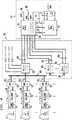
図4は、現時点において好ましいとされる網トポロジを示す略ブロック図であり;そして
図5は、本発明の代替実施例の略ブロック図である。
好ましい実施例の詳細な説明
図1には、本発明によるビデオ電話呼システム10の一つの好ましい実施例が示される。システム10は、発呼者のビデオ電話装置12の所から発信されたビデオ電話呼を、受信者の従来の電話装置60、およびケーブルテレビ62、に送信することを可能にする。ケーブルテレビ62は、典型的には、ビデオ画像を表示するためのモニタおよび複数の利用可能なテレビジョンチャネルの一つに選択的に同調するためのチューナを含む。ここで使用される“ビデオ電話装置”および/あるいは“ビデオ電話機”という用語は、同義的に使用され、音声信号およびビデオ信号を同時に、通信網を通じて送信する能力を持つ任意の装置を意味することを意図し、これには、これに限定されるものではないが、一例として、AT&T社のPicturephoneあるいはこれと同等な物、並びに、ビデオカメラおよびソフトウエアを利用するパーソナルコンピュータ、例えば、Intel社のProShare Personal Conferencingあるいはこれと同等な物が含まれる。ここで使用される“信号”という用語は、電気的、電磁的あるいは光学的な形式の、アナログあるいはデジタル信号を意味することを意図する。
システム10を使用する発呼者が、ビデオ電話機12から、ビデオ電話呼を開始するために、専用の電話番号へ発呼すると、この呼が、発呼者の電話回線14を通じて、後により詳細に説明される、集中呼転送センタ20へと運ばれる。呼転送センタ20は、受信者の電話番号を得、そして、電話網26内のビデオ電話回線22を介して、ビデオ電話ユニット(VDU)30との間に通信を設定する。VDU30は、これについても後により詳細に説明されるが、好ましくは、電話網内に置かれ、電話網の一部分を構成し、複数の音声/ビデオチャネル上の複数のビデオ呼を扱うための、ハードウエア、ソフトウエアおよび/あるいはファームウエアを含む。
VTU30は、各々がケーブルTVチャネルに専用に割当てられた、複数のビデオ電話回線22と関連する。呼転送センタは、各ビデオ電話回線22の状態を維持し、このために、どの回線が、従って、どのケーブルTVチャネルが、受信者の位置の所で、利用できるかを知っている。そして、VTU30は、いったん、呼転送センタ20と接続されると、ケーブルTV網内に位置しケーブルTV網の一部分を構成する、チャネル阻止ユニット52に対して、割当てられたチャネル上の任意のチャネル阻止を解除し、ビデオ呼を、受信者のケーブルTV62の位置で受信できるようにする。呼者は、次に、呼転送センタ20から、受信者が同調すべきケーブルTVチャネルについて知らされる。呼のプライバシを保護する目的で、呼のビデオ部分は、受信者のケーブルTVに、受信者によって、その受信者のケーブルTVによってのみ見ることができるような方法にて送信される。このプライバシの保護は、一般的に知られているCATV阻止技術を使用することによって、あるいはスクランブルによって、あるいは他の暗号化方法を使用し、これを、個々の受信者のケーブルTVのレベルにおいて、あるいはCATVヘッドエンドにおいて、あるいは、CATV分配システム内の他の箇所において、提供することによって達成される。ここで使用される“阻止”および/あるいは“阻止の働いている”という用語は、特定のケーブルサービス加入者位置の所で、特定のビデオ信号を受信することを、選択的に許可あるいは禁止する全ての技術を意味することを意図される。
VTU30は、呼を受信すると、呼を音声信号成分と、ビデオ信号成分に分離する。呼の音声部分は、電話網26内の網電話回線32を通じて、受信者の電話サービスに送られ、典型的には、受信者のローカル電話中央局(CO)40を通じて、ここから、受信者の電話回線68を通じて、受信者の従来の電話機60へと接続される。こうして、いったん接続されると、発呼者は、受信者に対して、割当てられたケーブルTVチャネルに同調するように指示し、これによって、呼のビデオ部分を同時に見ることが可能になる。ここで使用される“電話サービス”という用語は、発呼者および/あるいは受信者に電気通信サービスを提供する任意の構成要素あるいは会社、あるいは複数の構成要素あるいは会社の組合せを指すことを意図される。
他方、VTU30の所で分離された呼のビデオ部分は、ビデオ送信回線34を通じて、呼の受信者のケーブルサービス会社のケーブルTVヘッドエンド50に送られ、ここからさらに、ケーブルTV(CATV)分配システム54を通じて、受信者の個々のケーブルTV回線66へ送信され、受信者のケーブルTV62で受信し、見ることが可能になる。
ここで使用される“ケーブルテレビジョンサービス”という用語は、発呼者および/あるいは受信者に、ケーブルTVサービスを提供する任意の構成要素あるいは会社、あるいは複数の構成要素あるいは会社の組合せを指すことを意図される。また、ここで使用される“ケーブルTV”、“ケーブルテレビジョン”および/あるいは“CATV”という用語は、同義的に使用され、これらは、分配媒体の種類とは無関係に、無料の空中放送システムとは対照的に、阻止を採用する加入者TVの全ての形式を含むことを意図し、具体的には、これに限定されるものではないが、一例として、subscription and pay-per-view(加入しておき、見た番組に対して支払う方式の)ケーブルTVサービス、over-the-airsubscriptionTV(空中を通じて放送される加入者TV)、衛星システム、その他が含まれる。従って、“ケーブル”という用語は、単に、解説のために使用されるものであり、全てのTV分配媒体を含むことが意図され、これには、一例として、これに限定されるものではないが、同軸ケーブル、ツインリード、光ファイバストランド(より糸)、導波管、衛星アンテナ、その他の、信号を分配するための無線形式などが含まれる。
加えて、ここで使用される“電話網”および“通信網”という用語は、標準の音声のみのおよび/あるいはビデオ電話呼を、ある位置から別の位置に運ぶための、任意のおよび全ての手段を含むことを意図され、LATA間であるかあるいはLATA内であるかは問われず、また、私設網内であるかCO内であるか、あるいは、有線であるか無線であるかも問われない。ここで示されるあるいは使用される任意の特定な信号経路、例えば、電話回線14、22、32、68、114および122は、単に、解説を目的とするものであり、網を通じての呼の完成は、複数の信号経路に及ぶとも、複数の信号搬送媒体を通じるとも、複数の網ノードを通じるとも考えられ、これらの全てのルーティングは、電話網設計者においては周知であることを認識されるべきである。
呼転送センタ
呼転送センタ20は、上で述べたように、発呼者によって発信されたビデオ呼を受信する、システム内の最初のポイントである。図2に示されるように、呼転送センタ20は、複数のビデオ電話回線14を通じて複数の入りビデオ呼を扱うための装置を含む。転送センタ20は、好ましくは、ビデオ呼システム10を提供する会社によって宣伝される専用の電話番号をダイヤルすることによって到達される。転送センタの番号は、例えば“1−900”番号とされ、割増料金がこの呼に自動的に加算されるようにされる。加えて、異なるビデオプロトコルを利用する入り呼の敏速な取り扱いを容易にするために、転送センタ20は、発呼者によって所有されるビデオ電話装置のタイプごとの一連の異なる電話番号によって到達するようにすることも考えられる。こうして、例えば、AT&T社のPicturephoneの所有者は、1-900-ATT-VID1をダイヤルし、一方ProShareの所有者は、例えば、1-900-PRO-SHARをダイヤルするようにされる。別の方法として、単一の番号を宣伝し、発呼者のビデオ電話機12によって使用される特定のビデオプロトコルを、ユーザに入力を催促することによって決定、あるいは、転送センタ20の所に設置されたビデオプロトコルセンサ24を使用して自動的に決定することも可能である。プロトコルセンサ24によるビデオプロトコルの検出は、当分野において周知のハードウエアおよびソフトウエア技術を使用して、簡単に達成できるものである。
いずれにしても、転送センタ20は、ビデオ呼を電話回線14を通じて受信し、音声合成ユニット37を通じて、あるいは、手操作のオペレータ(図示なし)を通じて、発呼者から、意図される呼の受信者の電話番号を確定する。ここで使用される“音声合成”という用語は、コンピュータによるテキストから音声へおよび/または音声からテキストへの合成、並びに、あらかじめ録音されたメッセージあるいはメッセージの断片を利用するタッチトーン音声応答システム、あるいは、当分野において認識されている他の同等な技術を指すとこを意図される。音声合成、あるいは、タッチトーン音声応答による呼の受信者の電話番号の捕捉は、当分野において周知のハードウエアおよびソフトウエアによって遂行することが可能であり、このために、ここでは詳細な説明は必要でないと考える。ここで、手操作のオペレータの使用は、次善の代替である。
意図される呼の受信者の電話番号を確認すると、次に、転送センタ20は、電話網26を介しての通信を、ビデオ電話回線22と関連する電話番号をダイヤルすることによって設定するが、ビデオ電話回線22は、VTU30に接続されており、VTU30は、呼の受信者のローカル電話およびケーブルシステムを扱う。この転送センタ20と、受信者の位置と関連する適当なVTU30との間の通信のルーティングおよび設定は、好ましくは、この電話網内のハードウエアおよびソフトウエアによって遂行されるが、この設計および実現は、電話網のルーティングを担当する技術者には、容易に理解できるものである。また、ビデオ電話回線22の使用は、純粋に、解説を目的とするものである。
VTU30が、呼をそれを通じて完成することが可能な利用できる音声/ビデオチャネルを持つか否か決定するために、転送センタ20は、VTUチャネル状態ユニット39および検索テーブル38を利用する。上で説明されたように、各ビデオ電話回線22は、VTU30内の一つのチャネル33、並びに、一つのケーブルTVチャネルを表す。転送センタ20は、それがダイヤルした各ビデオ電話回線22の状態を、チャネル状態ユニット39内に維持する。この方法によって、転送センタ20は、あるビデオ電話回線が呼を完成するために利用できるか否か、および、またどのケーブルTVチャネルが使用されるべきかを知る。別の方法として、ケーブルTVチャネルの割当てが動的に行なわれる場合は、チャネル状態ユニット39内に、後により詳細に説明されるように、連続してVTU30の複数の音声/ビデオチャネルの定期的状態を照会することを遂行するためのハードウエアおよびソフトウエアを組み込むことも可能である。この照会は、ビデオ電話回線22を介して行なうことも、あるいは、独立のVTU状態回線35を通じて行なうことも可能である。これらは単に設計上の選択の問題であり、周知の回線状態検出技術を使用して達成することができる。いずれにしても、VTUチャネル状態に関する情報が、転送センタ20の所で、VTUチャネル検索テーブル38内に維持される。検索テーブル38は、複数の一般に提供されているデータベースおよび/あるいはソフトウエア設計ツールを利用して実現することが可能である。
検索テーブル38が、VTU30内の音声/ビデオチャネル33が利用できることを示す場合、そのチャネルが、ビデオ呼を運ぶために利用されるように選択され、対応するビデオ電話回線22の電話番号が、転送センタ20によってダイヤルされ、転送センタ20は、発呼者および/あるいは受信者に、音声合成ユニット37にて、あるいは、使用される場合は、手操作のオペレータによって、呼のビデオ部分を運ぶケーブルTVチャネルについて知らせる。別の方法として、VTU30が、データ回線36を通じて、ケーブルTVヘッドエンド50に、呼の受信者の位置の利用できるCATVチャネルを照会するようにすることも可能である。ヘッドエンド50の所で得られたCATVチャネル割当て情報が、VTU30によって、転送センタ20に送られ、これが、音声合成ユニット37によって、あるいは、使用される場合は、手操作のオペレータによって、発呼者および/あるいは受信者に中継されることとなる。受信者は、すると、上に説明されたように、指定されたCATVチャネルに同調する。
ビデオ電話ユニット(VTU)
VTU30は、複数のビデオ電話呼を同時に扱うための複数の音声/ビデオチャネルを提供する。図3に示されるように、一例としてのVTU30は、複数の音声/ビデオチャネルMからNを持つように示されるが、典型的な音声/ビデオチャネルが、参照番号33によって示される。VTU内の音声/ビデオチャネルのおのおのは、類似の要素を含み、類似に動作する。網を通じて流れるビデオ呼の容量を予測し、これを扱うためにどの程度の数のVTUが要求されるかを決定する問題は、設計上の選択の問題であり、電話網トラフィックの設計者における問題である。
タッチトーンおよびオフフック検出器47が、各入りビデオ電話回線22に接続される。検出器47は、ビデオ電話回線22上で回線ビジー状態(オフフック状態)あるいは回線利用状態(オンフック状態)をシミュレートすることによって、VTUチャネル状態ユニット39によって利用されるチャネル利用情報を提供する。上に説明されたように、転送センタ20は、それがどのビデオ電話回線22にダイヤルしたかを、従って、どのVTUチャネル33が使用のために利用できるかを知っている。別の方法として、このチャネル状態情報を、ビデオ電話回線22を通じて、あるいは、VTU状態回線35を介して、転送センタ20に、動的にパスすることも可能である。オンフックのVTUチャネルが識別されると、そのVTUチャネルと転送センタ20との間に、接続が、設定されるが、これは、転送センタ20が、そのチャネルのビデオ電話回線22と関連する電話番号をダイヤルすることによって行なわれる。いったん呼が設定されると、検出器47は、その状態をオフフックに変更する。
図1および図3を参照しながら説明を続けるが、上で述べられたように、各VTU30は、専用の電話番号によって到達される専用のビデオ電話回線22を持つチャネルMからNとして示される複数のチャネル33を含み、各VTUチャネル33は、ケーブルTVヘッドエンド50の所の特定のケーブルTVチャネルにも専用に用いられる。ケーブルTVサービスは、各VTUに、そのVTU内のチャネル33の数に等しい数のケーブルTVチャネルの数を割当てる。そして、これらケーブルTVチャネルは、VTU30によって管理される。呼が転送センタ20に到達すると、接続のための次に利用できる(ビジーでない)VTUチャネル33を探す。次に、利用できるVTUチャネルが、そのチャネルのビデオ電話回線22を介して転送センタ20に接続され、その状態が、ビジー(オフフック)に変更される。次に、この呼は、後に説明されるように、音声成分とビデオ成分に分割される。ビデオ成分は、次に、マルチチャネル送信機44の一つのチャネルを通じて、ケーブルTVサービスによって放送される周波数にて送信される。次に、阻止を持つ番組変更機53が、受信者の住居のケーブルTVチャネル上にプライバシを保護する目的で存在する任意の阻止を、直接に解除するか、あるいは、ケーブルTVヘッドエンド50に、これを解除するように指令する。阻止を持つ番組変更機53は、チャネル阻止を、呼が終了したとき、つまり、その呼を運ぶVTUチャネル33がオンフック状態に戻ったとき、再開させる。
別の方法として、チャネル割当てが動的に遂行される場合は、検出器47は、転送センタ20から、呼の受信者の電話番号を受信し、この番号に基づいて、受信者の住宅の所で利用できる空いたTVチャネルについて受信者のケーブルTVヘッドエンド50に示し、照会する。この照会は、データ回線36及び阻止を持つ番組変更機53を通じて送られ、割当てられたケーブルチャネルが、これと同一の経路を通じて、転送センタに送り返され、次に、上に説明されたように、転送センタ20を通じて発呼者に送られる。阻止を持つ番組変更機は、データ回線36を通じてケーブルTVヘッドエンド50に信号を送ることによって、ヘッドエンド50に対して、受信者の住居の所の割当てられたケーブルチャネル上に存在する任意のチャネル阻止を解除するように指令する。この阻止解除信号は、ケーブルTVヘッドエンド50から、CATV分配システム54を通じて、受信者のCATVシステム内に位置する阻止ユニット52に向けて、従来のpay-per-view(番組ごとに料金を支払う契約の)番組が配信されるのと同一の方法でルートされる。使用される特定の阻止スキームは、ケーブルシステムによって様々であり、従って、どのような阻止解除技法を実現するかは、設計選択のシステムに合わせて選択されるべき事項である。
図3に再び戻り、ビデオ電話呼は、ビデオ電話回線22を通じて受信され、この呼の音声およびビデオ信号成分が、ビデオ端末エミュレータ45に供給され、エミュレータ45は、転送センタ20によって検出され、これから送られてきたプロトコルに基づいて、発呼者のビデオ電話機12と同一のタイプのビデオ電話機をエミュレートする。エミュレータ45は、また、音声信号成分と、ビデオ信号成分を、受信者の家に別個にルートするために、分離する。音声信号成分は、標準の電話要素46を通じて、従来の電話回線32を通じて、電話網26を通じて転送し、受信者のローカル中央局40を通じて、ここから、呼の受信者の電話回線68を通じて、受信者の住宅内の標準の電話機60へと、従来の電話呼と殆ど同様にルートされる。ただし、ビデオ信号成分の方は、無線周波数(RF)ビデオ信号に変換され、マルチチャネルRFビデオ送信機44の一つのチャネルを介して、RFビデオ回線34を通じて、受信者のケーブルTVヘッドエンド50及びCATV分配システム54へと送られる。このRF信号は、ケーブルTVチャネル信号の形式を取ることも、あるいは、代替の形式を取り、ヘッドエンド50の所で、ケーブルチャネル信号に変換されることもできる。ビデオ信号は、次に、受信者の個々のケーブルTV回線66を通じてルートされ、従来のpay-per-view(番組ごとに支払うように契約された)テレビジョン番組と殆ど同様な方法にて、前以て阻止を解除されたケーブルTVチャネルを通じて配信される。呼が終了すると、一端検出器47は再びオンフック状態に戻り、番組変更機53は、直接に再開するよう信号を送りまたはそのように構成されている場合は、受信者の住宅の所の割当てられたケーブルTVチャネル上のチャネル阻止を再開するようにケーブルTVヘッドエンド50に信号を送る。このチャネルは、次に、空き状態となり、他のビデオ電話呼を扱えるようになる。勿論、ビデオ信号成分は、網の設計基準およびCATVヘッドエンドの容量および要件から指令される場合は、RF以外の任意の当分野において周知の送信可能な形式に変換することも可能であることが理解される。
検出器47、エミュレータ45およびプログラム変更機53は、ハードウエア、ソフトウエア、および/あるいはファームウエアのいずれで実現することも可能であり、これらは設計選択の上での一般的問題であり、各実現は、電話およびCATV要素の設計に習熟したものであれば、容易に可能である。エミュレータ45内に置かれる一般的なエミュレーションスキームとしては、これに限定されるものではないが、一例として、ベーシックレートおよび/あるいはプライマリレートインタフェースを利用する、International Telecommunications Union 320Yおよび/あるいはInternational Telecommunications Union H.320を使用することが考えられる。電話要素46は、網ベースの標準の電話機として機能するハードウエアおよび/あるいはファームウエア要素である。
設計上の代替
図4には、現時点において好ましいとされるシステムトポロジが示される。より詳細には、図4には、電話スイッチング要素とケーブルTV要素が、設備および分配媒体を共有する、AT&T HFC 2000網の一部分として実現されるシステム10が示される。この構成においては、ここで、以降、“結合型CO42”と呼ばれる、電話中央局とケーブルTVヘッドエンド42が結合された構成を持つ結合型CO42は、上に説明された多くの主要なシステム要素を収容する。
より詳細には、この結合型CO42内には、電話CO40、ケーブルTVヘッドエンド50、およびVTU30が、全て、共に位置される。標準のCATV資源番組は、CATV回線96を通じて受信され、標準の音声電話呼は、電話回線98を通じて受信される。ただし、ビデオ呼は、呼転送センタ20からビデオ電話回線22を通じて受信される。ここで、この呼転送センタ20は、この結合型CO内に共に位置することも、あるいは、別の位置に置くことも考えられる。この方法によると、ビデオ呼のビデオ部分と音声部分の受信者へのルーティングが、VTU30が、ビデオ呼が受信されたとき、その呼が、結合型CO42から出る共通の電話およびCATV分配網58に接続された受信者に向けられていることを、既に、“知っている”ために、大幅に簡素化される。
分配網58は、光ファイバケーブル94を介して結合型CO42に接続された一連のファイバノード90を含む。光ファイバケーブル94は、双方向信号搬送媒体であり、二重ストランド(より糸)、あるいは、単一ストランド(より糸)ファイバケーブルとして実現されるが、これは、単に、設計上の選択の問題である。VTU30によって分離され、ケーブルTVヘッドエンド50を通じて電話CO40に送られた音声信号成分とビデオ信号成分の両方は、ファイバケーブル94によって、ファイバノード90に運ばれ、ここからこれら信号は、さらに、一連の電話およびケーブル分配バス99へと送られる。ここで、分配バス99は、必要に応じて、同軸、ファイバ、あるいは、無線とされる。バス99からのファンアウトとして、同軸ケーブル95を介して接続された一連の網インタフェースユニット(NIU)92が存在するが、NIU92は、同軸ケーブル95を介して呼の音声信号成分およびビデオ信号成分を受信し、音声成分を、受信者の標準のチップアンドリング電話回線68にルートし、一方、ビデオ成分は、受信者の同軸回線62を通じてルートする。阻止ユニット52は、これが、番組変更機53および/あるいはケーブルTVヘッドエンド50からの信号に応答して、受信者の住宅の所の、呼のビデオ部分が運ばれる割当てられたケーブルチャネルから任意の阻止を、選択的に、解除できるという条件で、図示されるように、同軸回線62上に置くことも、あるいは、セツトトップケーブルボックスの一部分とすることも、ケーブルTVヘッドエンド50の一部分とすることも、あるいは、ケーブル分配システム(図示なし)内の適当な所に設置することも可能である。
勿論、様々なバリエーションが発明の精神から逸脱することなく上に説明された分配スキーム内で可能であることを理解できるものである。例えば、分配システム58全体を、ここで例示され説明されたのとは異なる、同軸、ファイバあるいは無線、あるいはこれら3つの組合せから構成することも可能である。あるいは、別の方法として、受信者が、呼全体を、ケーブルTV網を通じて、現在利用可能となっているローカル電話会社のバイパススキームを使用して受信できるようにし、これによって、呼がケーブルTVヘッドエンドにいったん到達したら、受信者のローカル電話会社が呼のルーティングに関与しなくても済むようにすることも可能である。
さらに、システムのさまざまな要素は、網分配トポロジ内に任意の位置に配備できるものであり、これらは、単に、設計上の選択の問題である。従って、転送センタ20、VTU30、電話CO40、ケーブルTVヘッドエンド50および阻止ユニット52は、全て独立して位置することも、全て共に位置することも、あるいは、一部分これらを組み合わせて位置することも可能である。上に説明された機能を達成するための要素の相互接続は、音声信号とビデオ信号が受信者の住宅の所で、これらが同時に、聴き、見ることができるように再結合されるという前提で、直接接続あるいは交換接続、共有網あるいは独立した網、のいずれを通じて行なうことも可能である。
加えて、ケーブル分配網部分全体を除去し、完全な双方向ビデオ呼機能を提供することも可能である。図5には、本発明のもう一つの実施例が示されるが、ここでは、プロトコルタイプ‘a’を利用するビデオ電話機112を持つ発呼者(図示なし)が、プロトコルタイプ‘b’を利用する互換性のないビデオ電話機160を所有する呼の受信者(図示なし)と通信することを望むことが想定される。このケースにおいては、発呼者は、上に説明された転送ユニット20と動作が類似する転送ユニット120に、発呼者の電話回線114を通じて発呼することとなる。すると、転送ユニット120は、呼をビデオ電話回線122を通じて、VTU130へとルートする。VTU130は、プロトコルタイプ‘a’とプロトコルタイプ‘b’間の双方向プロトコル変換を遂行する能力を持つ双方向プロトコルエミュレータを含む。VTU130は、呼を、電話網150を通じ、電話回線156を通じて、受信者のビデオ電話機160へとルートし、こうして、このビデオ呼は、あたかも、発呼者と受信者の両方が互換性のあるビデオ電話機を有するかのように接続される。プロトコル変換がVTUの所で遂行されるために、音声信号成分とビデオ信号成分の分離は要求されず、従って、分離のビデオ分配スキームは不要となる。プロトコル変換は、ハードウエア、ソフトウエアおよび/あるいはファームウエアにて遂行することができるが、これらは設計上の選択の問題であり、当業者においては周知である。上で説明されたように、網内での転送ユニット120、VTU130および/あるいはプロトコル変換機の特定な位置についても、設計上の選択の問題であり、網内に採用される特定の相互接続スキームについても、同様である。
本発明の好ましい実施例に適用される本発明の基本的な新規な点について示され、説明され、指摘されたが、当業者においては、ここに説明されたデバイスの形式および細部、並びに、これらの動作における、様々な省略、代替および変更が、本発明の精神から逸脱することなく、可能であることを理解できものである。例えば、実質的に同一の機能を、実質的に同一な方法にて遂行し、同一の結果を達成するこれら要素および/あるいは方法のステップの全ての組合せが、本発明の範囲に入ることを、ここに、明確に、表明するものである。従って、本発明は、ここに添付される請求の範囲によって示されるようにのみ限定されるものである。1.Field of Invention
The present invention relates to systems and methods for handling video telephone calls, and more particularly to providing video telephone call functionality over a combination of standard voice telephone lines and video cable TV lines.
2.Related technology description
Techniques for placing video telephone calls (ie telephone calls in which the audio portion of the conversation is transmitted over the telephone network along with the video image of the conversation) have been used for many years. However, in systems known today, each caller requires a video phone that is dedicated to transmitting and receiving both the video and audio portions of the telephone call.
On the other hand, the deployment of public video telephones has also started. Public video telephones eliminate the need for the caller to install a dedicated video telephone device at home. However, public video telephones require the caller and / or call recipient to go to the location where the public video telephone is installed. This reduces the attractiveness of this choice and reduces the willingness to make and receive video phone calls spontaneously.
On the other hand, personal computer-based devices have also been developed, but this technique likewise requires that the caller and receiver of a video telephone call have similar devices at their locations. In addition, each of the techniques described above utilizes a communication protocol that lies on a different base, which may cause one representation format of a videophone device to be incompatible with another. The lack of standardization and the need for both callers to have their own expensive equipment hinders the widespread use of this technology.
Thus, a caller with a video phone device can freely make a video phone call to a call recipient who does not own such a device or owns an incompatible device. There is a need to provide a method for achieving this.
Summary of invention
The present invention is directed to overcoming the disadvantages noted over the prior art. In a broad sense, the present invention provides a system that allows a caller located at a video phone to place a call to a recipient who does not have a video phone. The system transmits the audio portion of the conversation using a standard telephone line in a manner similar to a conventional telephone call without video, while the video portion of the conversation is cabled within the system. Sent through a television (CATV) facility for viewing on the television of the call recipient.
The system of the present invention connects to both the telephone network and the cable TV network for performing video transmissions, located within the system, over a cable TV channel that is dedicated and normally blocked. Use the device. The call recipient can watch the video portion of the call on the receiver's television simply by tuning to the designated cable TV channel, and the receiver's standard for the audio portion of the conversation. Carried using telephone equipment. In this way, a one-way video call can be placed even if the call recipient does not have dedicated video telephone equipment.
In use, a caller using a video phone terminal, public video phone or other video phone device initiates a call to a central video call transfer center. The equipment connected to the transfer center then determines the usage of the cable TV channel at the location of the call recipient, and the information about the call is passed to the head end of the recipient's cable TV company. In response, the end prepares to transmit the video portion of the call over the cable channel at the recipient location, which is usually blocked. The video portion of the call is then separated from the audio portion by a dedicated videotelephone unit located within the system as part of CATV or the telephone switching network, and the audio portion is telephoned in a traditional and traditional manner. It is routed through the network to the recipient's phone. When the audio part is connected, the caller's television is tuned to the designated cable channel by the caller or by the synthesized voice under the control of the transfer center. ,Reportedly. The video portion of the video phone call is then transmitted from the video phone unit through the cable TV company's headend, over the cable TV channel assigned during call setup, which is normally blocked. . If the call recipients have already tuned their television to the designated cable channel, they can watch the video portion of the call on the television, while the audio portion of the call It is carried in a conventional manner using a telephone.
Thus, according to the present invention, a video telephone user can make a video call to any person who owns the telephone and subscribes to cable television service. In addition, the same technology can be used for one-way video conferencing. In this case, one video phone caller makes a call to multiple cable television subscribers, and multiple recipients simultaneously view the video image generated by the video conference caller, You will hear the voice. Such a system is particularly useful for remote business meetings or distance education. In short, this allows potential call recipients on various platforms to receive a one-way video conferencing service without investing in equipment on the receiver side. In addition, the system of the present invention allows two parties with incompatible video devices to place interactive video calls. In this case, first the first caller places a video telephone call in the manner described above, and then the recipient uses the second telephone line to make a second call. And the video portion of the second call is transmitted to the first caller's cable television. Thereafter, both the calling party and the receiving party will be able to view the video portion of the call on their respective cable television.
As another embodiment, the video telephone unit can be equipped with a protocol conversion function, and the necessity of separating the voice communication path and the video communication path can be completely eliminated.
Other objects and features of the invention will become apparent from the following detailed description when read in conjunction with the accompanying drawings. In the following drawings, like reference numbers in the drawings represent like elements throughout the several views. These drawings are not shown to scale, and are provided solely for the purpose of illustration and are not intended to define the scope of the present invention. Accordingly, reference should be made to the appended claims for the scope of the invention.
[Brief description of the drawings]
FIG. 1 is a schematic block diagram of the major elements of the system of the present invention;
2 is a schematic block diagram of the elements of the call transfer center of the present invention;
FIG. 3 is a schematic block diagram of the elements of the video telephone unit of the present invention;
FIG. 4 is a schematic block diagram illustrating the currently preferred network topology; and
FIG. 5 is a schematic block diagram of an alternative embodiment of the present invention.
Detailed Description of the Preferred Embodiment
FIG. 1 shows one preferred embodiment of a video
When a caller using the
A
When receiving a call, the
On the other hand, the video portion of the call separated at the
As used herein, the term “cable television service” refers to any component or company or combination of components or companies that provides cable TV service to callers and / or recipients. Intended. Also, the terms “cable TV”, “cable television” and / or “CATV” as used herein are used interchangeably, and these are free aerial broadcast systems regardless of the type of distribution medium. In contrast, it is intended to include all forms of subscriber TV that employ blocking, specifically, but not limited to, subscription and pay-per-view ( Includes cable TV services that subscribe and pay for programs you watch, over-the-air subscription TV (subscriber TV broadcast over the air), satellite systems, and more. Thus, the term “cable” is used for illustrative purposes only and is intended to include all TV distribution media, including, but not limited to, by way of example. , Coaxial cables, twin leads, fiber optic strands, waveguides, satellite antennas, and other wireless formats for distributing signals.
In addition, as used herein, the terms “telephone network” and “communication network” refer to any and all of the standard voice-only and / or video telephone calls for carrying from one location to another. Is intended to include means, whether between LATAs or within LATAs, and whether it is in a private network or CO, or may be wired or wireless . Any particular signal paths shown or used herein, such as
Call transfer center
Call
In any case, the
Upon confirming the telephone number of the intended call recipient,
To determine whether
If the lookup table 38 indicates that an audio /
Video phone unit (VTU)
A touch tone and off-hook detector 47 is connected to each incoming
Continuing with reference to FIGS. 1 and 3, as described above, each
Alternatively, if channel assignment is performed dynamically, the detector 47 receives the telephone number of the call recipient from the
Returning again to FIG. 3, a video telephone call is received over the
The detector 47, the
Design alternative
FIG. 4 shows a currently preferred system topology. More particularly, FIG. 4 shows a
More specifically, in this combined
Of course, it will be understood that various variations are possible within the distribution scheme described above without departing from the spirit of the invention. For example, the
Furthermore, the various elements of the system can be deployed anywhere in the network distribution topology, and these are simply a matter of design choice. Thus, the
In addition, it is possible to eliminate the entire cable distribution network portion and provide full interactive video call functionality. FIG. 5 shows another embodiment of the present invention where a caller (not shown) having a
Although shown, described, and pointed out the basic novel features of the present invention as applied to preferred embodiments of the present invention, those skilled in the art will recognize the types and details of the devices described herein, as well as It will be understood that various omissions, substitutions, and changes in the operation may be made without departing from the spirit of the invention. For example, all combinations of these elements and / or method steps that perform substantially the same function in substantially the same way and achieve the same result fall within the scope of the invention, This is a clear statement. Accordingly, the invention is limited only as indicated by the claims appended hereto.
Claims (5)
Translated fromJapanese前記の発呼者からの前記のビデオ電話呼信号を、音声信号成分とビデオ信号成分に分離するための手段;
前記の呼の前記の音声信号成分を、前記の受信者の電話機において受信できるように、前記の受信者の電話サービスによる受信のために、従来の電話回線を介して送信する手段;および
前記の呼の前記のビデオ信号成分を、ケーブルテレビジョンチャネルによる前記のチューナを通じて、前記の受信者のケーブルテレビジョンモニタにおいて受信し、見る、ことができるように、前記の受信者のケーブルテレビジョンサービスによる受信のために前記従来の電話回線とは異なる無線周波数(RF)ビデオ回線を介して送信する手段を含むことを特徴とするシステム。A system for transmitting a video telephone call between a calling party having a video telephone apparatus and a receiver who subscribes to a telephone service including a telephone and a cable television service including a television tuner and a monitor. And this system is:
Means for separating the video telephone callsignal from the caller into an audio signal component and a video signal component;
Meansfor transmittingover a conventional telephone line for receipt by the recipient's telephone service so that the voice signal component of the call can be received at the recipient's telephone; and According to the receiver's cable television service, the video signal component of the call can be received and viewed on the receiver's cable television monitor through the tuner via a cable television channel. A system comprising means for transmittingover a radio frequency (RF) video line different from the conventional telephone line for reception.
発呼者のビデオ電話装置から音声信号成分とビデオ信号成分を含む信号を受信するための手段;
前記の受信手段に接続され、前記の音声信号成分とビデオ信号成分を、音声信号とビデオ信号に分離するための手段;
前記の分離手段に接続され、前記の音声信号を、前記の受信者の電話機によって受信されるために、従来の電話回線を介して前記の受信者の電話サービスに送信するための手段;および
前記の分離手段に接続され、前記のビデオ信号を、ケーブルテレビジョンチャネルによる、前記のチューナを通じて、前記の受信者のケーブルテレビジョンモニタによって受信されるように、前記従来の電話回線とは異なる無線周波数(RF)ビデオ回線を介して前記の受信者のケーブルテレビジョンサービスに送信するための手段を含むことを特徴とする装置。To facilitate a video telephone call between a caller having a video telephone device and a receiver who subscribes to the telephone service, has a telephone and subscribes to a cable television service and has a television tuner and monitor Equipment, which is:
Means for receiving a signal comprising an audio signal component and a video signal component from a caller's video telephone device;
Means connected to the receiving means for separating the audio signal component and the video signal component into an audio signal and a video signal;
Means for connecting to said separating means and for transmitting said voice signal to said recipient's telephone servicevia a conventional telephone line for receptionby said recipient's telephone; and Aradio frequency different from that of the conventional telephone line so that the video signal is received by the receiver's cable television monitor through the tuner via a cable television channel,(RF) An apparatus comprising means for transmitting to said recipient's cable television serviceover a video line .
発呼者からのビデオ電話呼信号を音声信号成分とビデオ信号成分に分離するステップ;
前記の呼の音声信号成分を、受信者の電話機によって受信されるように、従来の電話回線を介して送信するステップ;および
前記の呼のビデオ信号成分を、そこで見るために前記の受信者のケーブルテレビジョンチューナおよびモニタによって受信されるように、前記従来の電話回線とは異なる無線周波数(RF)ビデオ回線を介して送信するステップを含むことを特徴とする方法。To carry a video telephone call between a calling party having a video telephone device and a receiver who has subscribed to the telephone service and has a telephone and has a cable television service and a cable television tuner and monitor Method, this method:
Separating the video telephone callsignal from the caller into an audio signal component and a video signal component;
Transmitting the audio signal component of the call over aconventional telephone line so that it is received by the recipient's telephone; and the video signal component of the call to view the receiver's video signal component there Transmittingover a radio frequency (RF) video line different from the conventional telephone line as received by a cable television tuner and monitor.
発呼者によって、電話サービスに加入し電話機を有し、かつ、ケーブルテレビジョンサービスに加入しケーブルテレビジョンチューナおよびモニタを持つ呼の受信者に向けて発信されたビデオ電話呼信号を受信するステップ;
前記のビデオ電話呼信号を、音声信号成分とビデオ信号成分に分離するステップ;
前記の呼の音声信号成分を、さらに受信者の電話機に送信するために、従来の電話回線を介して受信者の電話サービスに向けて送信するステップ;および
前記の呼のビデオ信号成分を、さらにケーブルテレビジョンチャネルを通じて受信者のケーブルテレビジョンのチューナおよびモニタの上でこれが見られるように送信するために、前記従来の電話回線とは異なる無線周波数(RF)ビデオ回線を介して受信者のケーブルテレビジョンサービスに向けて、送信するステップを含むことを特徴とする方法。A method for operating a telephone network to handle video telephone calls, which method:
Receiving, by a caller, a video telephone callsignal transmitted to a call recipient who subscribes to a telephone service and has a telephone and subscribes to a cable television service and has a cable television tuner and a monitor; ;
Separating the video telephone callsignal into an audio signal component and a video signal component;
Transmitting the call audio signal component to a recipient telephone serviceover a conventional telephone line for further transmission tothe recipient telephone; and the call video signal component further The recipient's cablevia a radio frequency (RF) video line that is different from the conventional telephone line to transmit as seen on the receiver's cable television tuner and monitor through a cable television channel. A method comprising transmitting to a television service.
発呼者によって、電話機およびテレビジョンセットを有する呼の受信者に向けて発信されたビデオ電話呼信号を受信するステップ;
前記の発呼者からの前記のビデオ電話呼信号を、音声信号成分とビデオ信号成分に分離するステップ;
前記の呼の音声信号成分を、従来の電話回線を介して前記の受信者の電話機に送信するステップ;および前記の呼のビデオ信号成分を、前記従来の電話回線とは異なる無線周波数(RF)ビデオ回線を介して前記の受信者のテレビジョンセットに送信するステップを含むことを特徴とする方法。Thetelephone network, for handling video telephone call, a method of operating, the steps of:
Receiving a video telephone callsignal originated by a caller to a call recipient having a telephone and a television set;
Separating the video telephone callsignal from the caller into an audio signal component and a video signal component;
Transmitting the voice signal component of the callto the recipient's telephoneover a conventional telephone line ; and the video signal component of the call to aradio frequency (RF) different from the conventional telephone line. Transmitting to said recipient's television setover a video line .
Applications Claiming Priority (3)
| Application Number | Priority Date | Filing Date | Title |
|---|---|---|---|
| US08/579,709 | 1995-12-28 | ||
| US08/579,709US5790180A (en) | 1995-12-28 | 1995-12-28 | Video telephone call handling system and method |
| PCT/US1996/020486WO1997024876A1 (en) | 1995-12-28 | 1996-12-23 | Video telephone call handling system and method |
Publications (2)
| Publication Number | Publication Date |
|---|---|
| JPH11501493A JPH11501493A (en) | 1999-02-02 |
| JP3842294B2true JP3842294B2 (en) | 2006-11-08 |
Family
ID=24318025
Family Applications (1)
| Application Number | Title | Priority Date | Filing Date |
|---|---|---|---|
| JP52449697AExpired - Fee RelatedJP3842294B2 (en) | 1995-12-28 | 1996-12-23 | System and method for handling video telephone calls |
Country Status (5)
| Country | Link |
|---|---|
| US (1) | US5790180A (en) |
| EP (1) | EP0812512A4 (en) |
| JP (1) | JP3842294B2 (en) |
| CA (1) | CA2213432C (en) |
| WO (1) | WO1997024876A1 (en) |
Families Citing this family (25)
| Publication number | Priority date | Publication date | Assignee | Title |
|---|---|---|---|---|
| JP3237566B2 (en)* | 1997-04-11 | 2001-12-10 | 日本電気株式会社 | Call method, voice transmitting device and voice receiving device |
| USD402978S (en)* | 1997-11-13 | 1998-12-22 | Industrial Technology Research Institute | Stand alone videophone |
| JP4154015B2 (en)* | 1997-12-10 | 2008-09-24 | キヤノン株式会社 | Information processing apparatus and method |
| US6201562B1 (en) | 1998-10-31 | 2001-03-13 | Kar-Wing E. Lor | Internet protocol video phone adapter for high bandwidth data access |
| US7565680B1 (en)* | 2000-06-30 | 2009-07-21 | Comcast Ip Holdings I, Llc | Advanced set top terminal having a video call feature |
| US20030046705A1 (en)* | 2001-08-28 | 2003-03-06 | Sears Michael E. | System and method for enabling communication between video-enabled and non-video-enabled communication devices |
| DE60228706D1 (en)* | 2002-08-13 | 2008-10-16 | Ericsson Telefon Ab L M | A method of allowing access to video and audio data of a videotelephone call |
| CN1283125C (en)* | 2003-08-05 | 2006-11-01 | 株式会社日立制作所 | telephone communication system |
| US7636805B2 (en)* | 2003-10-20 | 2009-12-22 | Logitech Europe S.A. | Method and apparatus for communicating data between two hosts |
| EP1792483B1 (en)* | 2004-09-03 | 2015-08-19 | Telecom Italia S.p.A. | Method and system for video telephone communications set up, related equipment and computer program product |
| US7543064B2 (en)* | 2004-09-30 | 2009-06-02 | Logitech Europe S.A. | Multiplayer peer-to-peer connection across firewalls and network address translators using a single local port on the local host |
| US7573498B1 (en)* | 2004-12-01 | 2009-08-11 | Sprint Communications Company L.P. | System and method for providing video conferencing services to a television-service subscriber |
| US7738468B2 (en) | 2005-03-22 | 2010-06-15 | Logitech Europe S.A. | Method and apparatus for packet traversal of a network address translation device |
| JP4916726B2 (en)* | 2006-01-24 | 2012-04-18 | 株式会社日立国際電気 | Camera device |
| US8718257B2 (en) | 2006-07-10 | 2014-05-06 | Francesco Ricci | Systems and methods for providing answering services |
| CN101502083B (en)* | 2006-07-10 | 2014-01-22 | 新I.P.投资有限责任公司 | System and method for providing answering service |
| US20080009269A1 (en)* | 2006-07-10 | 2008-01-10 | New I.P. Investments, Llc | Method and system for management and routing of telecommunications on data and telephone lines |
| US7620393B2 (en)* | 2006-12-26 | 2009-11-17 | Motorola, Inc. | Method and system for managing communication devices |
| DE102008002276B4 (en)* | 2007-12-06 | 2011-02-03 | Hochschule für Film und Fernsehen "Konrad Wolf" | Method and arrangement for transmitting image data and a corresponding computer program and a corresponding computer-readable storage medium |
| US8339438B2 (en)* | 2008-12-24 | 2012-12-25 | Rockstar Consortium Us Lp | Web based access to video associated with calls |
| US8379632B2 (en) | 2009-05-26 | 2013-02-19 | General Instrument Corporation | Simultaneous delivery of a telephony call over a broadband access network and a circuit-switched network |
| KR101673032B1 (en) | 2010-01-25 | 2016-11-04 | 엘지전자 주식회사 | Video communication method and digital television thereof |
| US8767031B2 (en)* | 2012-08-20 | 2014-07-01 | Wolzien Llc | Video call center |
| EP2899957A1 (en)* | 2014-01-22 | 2015-07-29 | Phonetica Lab S.R.L. | System for integrating video calls in telephone call centers |
| US10979767B2 (en)* | 2019-04-29 | 2021-04-13 | See A Star LLC | Audio-visual content monitoring and quarantine system and method |
Family Cites Families (13)
| Publication number | Priority date | Publication date | Assignee | Title |
|---|---|---|---|---|
| US4450481A (en)* | 1981-08-25 | 1984-05-22 | E-Com Corporation | Tamper-resistant, expandable communications system |
| EP0116296B1 (en)* | 1983-02-10 | 1988-04-20 | KRONE Aktiengesellschaft | Method and device for signalling between picture phone sets at an existing telephone link |
| US4910791A (en)* | 1985-12-26 | 1990-03-20 | Am Communications, Inc. | Monitoring and control of data communications |
| US5014309A (en)* | 1988-03-10 | 1991-05-07 | Scientific-Atlanta, Inc. | Off-premises cable television channel interdiction method and apparatus |
| US5138649A (en)* | 1990-11-16 | 1992-08-11 | General Instrument Corporation | Portable telephone handset with remote control |
| US5327554A (en)* | 1990-11-29 | 1994-07-05 | Palazzi Iii Michael A | Interactive terminal for the access of remote database information |
| US5343240A (en)* | 1991-11-04 | 1994-08-30 | At&T Bell Laboratories | Bidirectional video telephony using shared channels on coaxial cable networks |
| US5278889A (en)* | 1992-07-29 | 1994-01-11 | At&T Bell Laboratories | Video telephony dialing |
| US5329308A (en)* | 1992-07-29 | 1994-07-12 | At&T Bell Laboratories | Bidirectional video telephony between cable television and switched telephone systems |
| US5440335A (en)* | 1993-05-28 | 1995-08-08 | U S West Advanced Technologies, Inc. | Method and apparatus for delivering passband and telephony signals in a coaxial cable network |
| US5592540A (en)* | 1993-05-28 | 1997-01-07 | U S West Advanced Technologies, Inc. | Method and apparatus for selectively delivering telephony signals on a hybrid coaxial cable network |
| US5512935A (en)* | 1994-03-31 | 1996-04-30 | At&T Corp. | Apparatus and method for diplaying an alert to an individual personal computer user via the user's television connected to a cable television system |
| US5574779A (en)* | 1995-05-01 | 1996-11-12 | Bell Communications Research, Inc. | Method and apparatus for provisioning network services |
- 1995
- 1995-12-28USUS08/579,709patent/US5790180A/ennot_activeExpired - Lifetime
- 1996
- 1996-12-23EPEP96944966Apatent/EP0812512A4/ennot_activeWithdrawn
- 1996-12-23CACA002213432Apatent/CA2213432C/ennot_activeExpired - Fee Related
- 1996-12-23WOPCT/US1996/020486patent/WO1997024876A1/ennot_activeApplication Discontinuation
- 1996-12-23JPJP52449697Apatent/JP3842294B2/ennot_activeExpired - Fee Related
Also Published As
| Publication number | Publication date |
|---|---|
| JPH11501493A (en) | 1999-02-02 |
| US5790180A (en) | 1998-08-04 |
| CA2213432A1 (en) | 1997-07-10 |
| WO1997024876A1 (en) | 1997-07-10 |
| CA2213432C (en) | 2001-04-03 |
| EP0812512A1 (en) | 1997-12-17 |
| EP0812512A4 (en) | 1999-08-04 |
Similar Documents
| Publication | Publication Date | Title |
|---|---|---|
| JP3842294B2 (en) | System and method for handling video telephone calls | |
| JP2820866B2 (en) | Videophone system and method of using the same | |
| US5329308A (en) | Bidirectional video telephony between cable television and switched telephone systems | |
| US5343240A (en) | Bidirectional video telephony using shared channels on coaxial cable networks | |
| JP3141947B2 (en) | Circuit arrangement for a telecommunication switching network, preferably a telephone switching network comprising switches | |
| US8054963B2 (en) | System with call forward profile | |
| US20020178454A1 (en) | Broadcast television and satellite signal switching system and method for telephony signal insertion | |
| KR20000016017A (en) | Access network over a shared medium | |
| JPS61281690A (en) | Method of performing tv conference and tv conference network | |
| AU730058B2 (en) | A method and an arrangement for integrated radio telecommunication via a CATV network | |
| CA2035376A1 (en) | Broadband private automatic branch exchange | |
| US7471648B2 (en) | Integrating video, voice and data traffic in a single conferencing system | |
| JP2001230819A (en) | IP dedicated line | |
| US5835845A (en) | Communication system of multi-channel access | |
| JP2594089B2 (en) | Two-way video communication system | |
| JP2874608B2 (en) | Three-way calling between a videophone exchange and a videophone | |
| JP3266180B2 (en) | CATV telephone system | |
| EP0806105B1 (en) | Teleconference system at telecommunications system, method for establishing of teleconference and teleconference equipment for use in a teleconference system | |
| JPH02177754A (en) | Subscriber's transmitter | |
| JPH04276972A (en) | Broad band exchange multiple address connection system | |
| JPH0837559A (en) | Image communication terminal receiving method |
Legal Events
| Date | Code | Title | Description |
|---|---|---|---|
| A521 | Request for written amendment filed | Free format text:JAPANESE INTERMEDIATE CODE: A523 Effective date:20040113 | |
| A911 | Transfer to examiner for re-examination before appeal (zenchi) | Free format text:JAPANESE INTERMEDIATE CODE: A911 Effective date:20040318 | |
| A912 | Re-examination (zenchi) completed and case transferred to appeal board | Free format text:JAPANESE INTERMEDIATE CODE: A912 Effective date:20040325 | |
| A601 | Written request for extension of time | Free format text:JAPANESE INTERMEDIATE CODE: A601 Effective date:20060228 | |
| A602 | Written permission of extension of time | Free format text:JAPANESE INTERMEDIATE CODE: A602 Effective date:20060309 | |
| A521 | Request for written amendment filed | Free format text:JAPANESE INTERMEDIATE CODE: A523 Effective date:20060623 | |
| A61 | First payment of annual fees (during grant procedure) | Free format text:JAPANESE INTERMEDIATE CODE: A61 Effective date:20060810 | |
| R150 | Certificate of patent or registration of utility model | Free format text:JAPANESE INTERMEDIATE CODE: R150 | |
| FPAY | Renewal fee payment (event date is renewal date of database) | Free format text:PAYMENT UNTIL: 20090818 Year of fee payment:3 | |
| FPAY | Renewal fee payment (event date is renewal date of database) | Free format text:PAYMENT UNTIL: 20100818 Year of fee payment:4 | |
| FPAY | Renewal fee payment (event date is renewal date of database) | Free format text:PAYMENT UNTIL: 20110818 Year of fee payment:5 | |
| FPAY | Renewal fee payment (event date is renewal date of database) | Free format text:PAYMENT UNTIL: 20110818 Year of fee payment:5 | |
| FPAY | Renewal fee payment (event date is renewal date of database) | Free format text:PAYMENT UNTIL: 20120818 Year of fee payment:6 | |
| FPAY | Renewal fee payment (event date is renewal date of database) | Free format text:PAYMENT UNTIL: 20120818 Year of fee payment:6 | |
| FPAY | Renewal fee payment (event date is renewal date of database) | Free format text:PAYMENT UNTIL: 20130818 Year of fee payment:7 | |
| R250 | Receipt of annual fees | Free format text:JAPANESE INTERMEDIATE CODE: R250 | |
| R250 | Receipt of annual fees | Free format text:JAPANESE INTERMEDIATE CODE: R250 | |
| LAPS | Cancellation because of no payment of annual fees |