JP3841149B2 - Single cell for solid oxide fuel cell - Google Patents
Single cell for solid oxide fuel cellDownload PDFInfo
- Publication number
- JP3841149B2 JP3841149B2JP2001134696AJP2001134696AJP3841149B2JP 3841149 B2JP3841149 B2JP 3841149B2JP 2001134696 AJP2001134696 AJP 2001134696AJP 2001134696 AJP2001134696 AJP 2001134696AJP 3841149 B2JP3841149 B2JP 3841149B2
- Authority
- JP
- Japan
- Prior art keywords
- electrode
- porous metal
- metal substrate
- fuel
- air electrode
- Prior art date
- Legal status (The legal status is an assumption and is not a legal conclusion. Google has not performed a legal analysis and makes no representation as to the accuracy of the status listed.)
- Expired - Fee Related
Links
Images


Classifications
- H—ELECTRICITY
- H01—ELECTRIC ELEMENTS
- H01M—PROCESSES OR MEANS, e.g. BATTERIES, FOR THE DIRECT CONVERSION OF CHEMICAL ENERGY INTO ELECTRICAL ENERGY
- H01M8/00—Fuel cells; Manufacture thereof
- H01M8/10—Fuel cells with solid electrolytes
- H01M8/12—Fuel cells with solid electrolytes operating at high temperature, e.g. with stabilised ZrO2 electrolyte
- H01M8/1213—Fuel cells with solid electrolytes operating at high temperature, e.g. with stabilised ZrO2 electrolyte characterised by the electrode/electrolyte combination or the supporting material
- H01M8/1226—Fuel cells with solid electrolytes operating at high temperature, e.g. with stabilised ZrO2 electrolyte characterised by the electrode/electrolyte combination or the supporting material characterised by the supporting layer
- H—ELECTRICITY
- H01—ELECTRIC ELEMENTS
- H01M—PROCESSES OR MEANS, e.g. BATTERIES, FOR THE DIRECT CONVERSION OF CHEMICAL ENERGY INTO ELECTRICAL ENERGY
- H01M2300/00—Electrolytes
- H01M2300/0017—Non-aqueous electrolytes
- H01M2300/0065—Solid electrolytes
- H01M2300/0068—Solid electrolytes inorganic
- H01M2300/0071—Oxides
- H01M2300/0074—Ion conductive at high temperature
- H—ELECTRICITY
- H01—ELECTRIC ELEMENTS
- H01M—PROCESSES OR MEANS, e.g. BATTERIES, FOR THE DIRECT CONVERSION OF CHEMICAL ENERGY INTO ELECTRICAL ENERGY
- H01M4/00—Electrodes
- H01M4/86—Inert electrodes with catalytic activity, e.g. for fuel cells
- H01M4/90—Selection of catalytic material
- H01M4/9016—Oxides, hydroxides or oxygenated metallic salts
- H01M4/9025—Oxides specially used in fuel cell operating at high temperature, e.g. SOFC
- H01M4/9033—Complex oxides, optionally doped, of the type M1MeO3, M1 being an alkaline earth metal or a rare earth, Me being a metal, e.g. perovskites
- H—ELECTRICITY
- H01—ELECTRIC ELEMENTS
- H01M—PROCESSES OR MEANS, e.g. BATTERIES, FOR THE DIRECT CONVERSION OF CHEMICAL ENERGY INTO ELECTRICAL ENERGY
- H01M4/00—Electrodes
- H01M4/86—Inert electrodes with catalytic activity, e.g. for fuel cells
- H01M4/90—Selection of catalytic material
- H01M4/9041—Metals or alloys
- H01M4/905—Metals or alloys specially used in fuel cell operating at high temperature, e.g. SOFC
- H01M4/9066—Metals or alloys specially used in fuel cell operating at high temperature, e.g. SOFC of metal-ceramic composites or mixtures, e.g. cermets
- H—ELECTRICITY
- H01—ELECTRIC ELEMENTS
- H01M—PROCESSES OR MEANS, e.g. BATTERIES, FOR THE DIRECT CONVERSION OF CHEMICAL ENERGY INTO ELECTRICAL ENERGY
- H01M8/00—Fuel cells; Manufacture thereof
- H01M8/02—Details
- H01M8/0202—Collectors; Separators, e.g. bipolar separators; Interconnectors
- Y—GENERAL TAGGING OF NEW TECHNOLOGICAL DEVELOPMENTS; GENERAL TAGGING OF CROSS-SECTIONAL TECHNOLOGIES SPANNING OVER SEVERAL SECTIONS OF THE IPC; TECHNICAL SUBJECTS COVERED BY FORMER USPC CROSS-REFERENCE ART COLLECTIONS [XRACs] AND DIGESTS
- Y02—TECHNOLOGIES OR APPLICATIONS FOR MITIGATION OR ADAPTATION AGAINST CLIMATE CHANGE
- Y02E—REDUCTION OF GREENHOUSE GAS [GHG] EMISSIONS, RELATED TO ENERGY GENERATION, TRANSMISSION OR DISTRIBUTION
- Y02E60/00—Enabling technologies; Technologies with a potential or indirect contribution to GHG emissions mitigation
- Y02E60/30—Hydrogen technology
- Y02E60/50—Fuel cells
- Y—GENERAL TAGGING OF NEW TECHNOLOGICAL DEVELOPMENTS; GENERAL TAGGING OF CROSS-SECTIONAL TECHNOLOGIES SPANNING OVER SEVERAL SECTIONS OF THE IPC; TECHNICAL SUBJECTS COVERED BY FORMER USPC CROSS-REFERENCE ART COLLECTIONS [XRACs] AND DIGESTS
- Y02—TECHNOLOGIES OR APPLICATIONS FOR MITIGATION OR ADAPTATION AGAINST CLIMATE CHANGE
- Y02P—CLIMATE CHANGE MITIGATION TECHNOLOGIES IN THE PRODUCTION OR PROCESSING OF GOODS
- Y02P70/00—Climate change mitigation technologies in the production process for final industrial or consumer products
- Y02P70/50—Manufacturing or production processes characterised by the final manufactured product
Landscapes
- Life Sciences & Earth Sciences (AREA)
- Engineering & Computer Science (AREA)
- Manufacturing & Machinery (AREA)
- Sustainable Development (AREA)
- Sustainable Energy (AREA)
- Chemical & Material Sciences (AREA)
- Chemical Kinetics & Catalysis (AREA)
- Electrochemistry (AREA)
- General Chemical & Material Sciences (AREA)
- Fuel Cell (AREA)
Description
Translated fromJapanese【0001】
【発明の属する技術分野】
本発明は、固体電解質を用い、電気化学反応により電気エネルギーを得る固体電解質型燃料電池(SOFC)用の単セルに係り、更に詳細には、固体電解質を電極で挟持して成る固体電解質型燃料電池用単セル及びその製造方法に関する。
【0002】
【従来の技術】
従来から、2つの電極、即ち燃料極(アノード)と空気極(カソード)で固体酸化物電解質を挟持する構成を発電要素としてもち、燃料極側に水素、メタンなどの炭化水素系燃料ガスを通じ、空気極側側に酸素、空気などの酸化性ガスを通じて発電する固体電解質型燃料電池(以下「SOFC」と略す)が知られている。
かかるSOFCは、その発電効率が高く、また排熱利用も可能であり第三世代の燃料電池として期待されている。
【0003】
従来から知られているSOFCのセル構造としては、図1に示すような電解質支持型セルを例示できる。このセルは、電解質材料粉を高密度に焼結して緻密電解質体12とし、その表裏にスクリーン印刷等で燃料極10及び空気極11を形成して成る。また、このセルは電解質を発電要素の支持部材として使用している。
また、他の例として、図2に電極支持型セルを例示する。このセルは、電極材料粉を焼結し多孔質電極体10とし、その上に電解質層12及び電極層11をスクリーン印刷等で形成して成る。更に、このセルは、多孔質電極体を発電要素の支持部材として使用している。
【0004】
具体的には、特開平9−50812号公報では、気孔率が板厚方向に異なるセラミックス電極材料粉の焼結体より成る多孔質電極基板が報告されている。
また、特開平2000−200614号公報では、同様にセラミックス電極材料粉の焼結体より成る多孔質電極基板が報告されている。
更に、燃料極/電解質/空気極(以下「発電要素」と略す)の支持部材として、図3に示すような燃料極10/電解質12/空気極11を多孔質金属基体1に溶射法にて製膜したセルが報告されている。
更にまた、DLRセル(Plasma Sprayed Thin−FilmSOFC for Reduced Operating Temperature ,Fuel Cells Bulletin,pp597−600,2000)が提案されている。
【0005】
また、特開平7−45297号公報、実開昭63−106063号公報などで開示されているように、従来から知られているSOFCでは、燃料極、空気極で発生した電力を集電するために電極とは別個にNiフェルトなどの集電体が使用されている。
更に、かかるSOFCは、多数の電池要素を電気的に直列又は並列に接続して使用されており、その際に、各電池要素を電気的に接続する部材(以下「I.C.(インタコネクタ)」と略す)を必要としている。このI.C.は集電体機能を備える場合もある。
更にまた、SOFCは、燃料極側に水素、メタンなどの炭化水素系燃料ガスを、空気極側側に酸素、空気などの酸化性ガスを通じて発電するため、ガスを電極表面に導くためのガス流路を形成する部材を必要とする。このガス流路はI.C.機能を備える場合もある。
【0006】
【発明が解決しようとする課題】
しかしながら、図1に示す電解質支持型セルは、電解質を発電要素の支持部材として使用するため、電解質の厚みは機械的な強度要請からおおよそ数百μm〜数mmとなり、電解質部分の内部抵抗が増加することがあった。
また、図2に示す電極支持型セルは、電極を発電要素の支持部材として使用するため、電極体の厚みは機械的な強度要請からおおよそ数mm以上となり、電極部分の内部抵抗が増加することに加え、燃料ガス又は酸化性ガスの通気性・拡散性が悪化することがあった。
更に、通気性を改善した特開平9−50812号公報及び特開平2000−200614号公報に開示された多孔質セラミックス電極基板は、電気伝導に対して十分ではなく、またセラミックス材料特有の脆性がある。
更にまた、I.C.及びガス流路部材は、図1及び図2に示したセルとは別個に設置する必要があり、SOFCの小型化の障害となっていた。
【0007】
また、図3に示したセルでは、▲1▼溶射成膜の制約のためか、電極、電解質の各膜厚が数十μmと厚く、内部抵抗が減じられない、▲2▼多孔金属体表面が粗いためか、電極、電解質を薄膜化できず内部抵抗を減じられない、▲3▼セル下部燃料極へのガス流路として、多孔質金属体をガス流路として使用せず、概凹状断面を有するプレートを使用しているためセル小型化が図れない、▲4▼セル上部空気極へのガス流路として、多孔質金属体をガス流路として使用せず、概波状断面を有するプレート15を使用しているためセル小型化が図れない、ことがあった。
【0008】
本発明は、このような従来技術の有する課題に鑑みてなされたものであり、その目的とするところは、電極(空気極及び燃料極)及び固体電解質を薄膜化して内部抵抗を低減し、小型化を達成した固体電解質型燃料電池用単セル及びその製造方法を提供することにある。
【0009】
【課題を解決するための手段】
本発明者らは、上記課題を解決すべく鋭意検討を重ねた結果、電池要素の支持基体として所望の強度を有する多孔性金属基体を用い、電池出力の集電機能とガス流路機能を担わせることにより、上記課題が解決できることを見出し、本発明を完成するに至った。
【0010】
即ち、本発明の固体電解質型燃料電池用単セルは、固体電解質を空気極及び燃料極で挟持して成る挟持体の表面及び/又は裏面に多孔質金属基体を被覆して成る固体電解質型燃料電池用の単セルであって、
上記多孔質金属基体が、ニッケルクロム鉄又は鉄クロムアルミを含む合金であり、燃料ガス及び/又は酸化性ガスを流通するとともに上記挟持体が形成する反応場より電池出力を集電することを特徴とする。
【0011】
また、本発明の他の固体電解質型燃料電池用単セルは、固体電解質を空気極及び燃料極で挟持して成る挟持体の表面及び/又は裏面に多孔質金属基体を被覆して成る固体電解質型燃料電池用の単セルであって、
上記多孔質金属基体が、ニッケル又は銀をセラミックスにメッキして成り、燃料ガス及び/又は酸化性ガスを流通するとともに上記挟持体が形成する反応場より電池出力を集電することを特徴とする。
【0012】
更に、本発明の固体電解質型燃料電池用単セルの好適形態は、上記多孔質金属基体を被覆された空気極及び/又は燃料極が、1〜50μmの厚さであることを特徴とする。
【0013】
更にまた、本発明の固体電解質型燃料電池用単セルの他の好適形態は、上記固体電解質が、50μm以下の厚さであることを特徴とする。
【0014】
また、本発明の固体電解質型燃料電池用単セルの更に他の好適形態は、上記多孔質金属基体が、0.5〜5mmの厚さであることを特徴とする。
【0015】
更に、本発明の固体電解質型燃料電池用単セルの他の好適形態は、上記多孔質金属基体が、空孔率の異なる同種又は異種の多孔質基体層を2層以上積層して成る積層体であることを特徴とする。
【0017】
また、本発明の固体電解質型燃料電池用単セルの製造方法は、多孔質金属基体、空気極、燃料極及び固体電解質を加熱及び加圧して接合し、上記固体電解質型燃料電池用単セルを製造するに当たり、
多孔質金属基体Aに空気極又は燃料極を被覆する工程と、該空気極又は燃料極に固体電解質を被覆する工程と、該固体電解質に燃料極又は空気極を被覆する工程と、該燃料極又は空気極に多孔質金属基体Bを被覆する工程と、を行うことを特徴とする。
【0018】
更に、本発明の固体電解質型燃料電池用単セルの他の製造方法は、多孔質金属基体、空気極、燃料極及び固体電解質を加熱及び加圧して接合し、上記固体電解質型燃料電池用単セルを製造するに当たり、
多孔質金属基体Aに空気極又は燃料極を被覆する工程と、該空気極又は燃料極に固体電解質を被覆する工程と、多孔質金属基体Bに燃料極又は空気極を被覆する工程と、該多孔質金属基体Aと該多孔質金属基体Bとを該空気極及び燃料極が該固体電解質を挟持するように接合する工程と、を行うことを特徴とする。
【0019】
【発明の実施の形態】
以下、本発明の固体電解質型燃料電池用単セルについて詳細に説明する。なお、本明細書において、「%」は特記しない限り質量百分率を示す。
また、説明の便宜上、基体や電極などの一方の面を「表面」及び「上面」、他の面を「裏面」及び「下面」などと記載するが、これらは等価な要素であり、相互に置換した構成も本発明の範囲に含まれるのは言うまでもない。
【0020】
かかる固体電解質型燃料電池用単セル(以下「単セル」と略す)は、固体電解質を空気極及び燃料極で挟持して成る挟持体の表面及び/又は裏面に多孔質金属基体を被覆して成る。
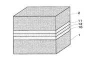
例えば、図4に示すように上記挟持体の一方の面に多孔質金属基体1を被覆した単セル(多孔質金属基体1/燃料極10/固体電解質12/空気極11、又は多孔質金属基体1/空気極10/固体電解質12/燃料極11の構成を採る)や、図5に示すように上記挟持体の両面に多孔質金属基体1及び2を被覆した単セル(多孔質金属基体1/燃料極10/固体電解質12/空気極11/多孔質金属基体2、又は多孔質金属基体1/空気極10/固体電解質12/燃料極11/多孔質金属基体2の構成を採る)を挙げることができる。なお、図4に示す構成の単セルを用いてスタックを形成するときには、上記挟持体が多孔質金属基体1に挟まれる構成となることはいうまでもない。
【0021】
また、本発明の単セルは、上記多孔質金属基体が、燃料ガス及び/又は酸化性ガスを流通するとともに上記挟持体が形成する反応場より電池出力を集電することを特徴とする。
これより、図5に示す構成の単セルでは、図6に示すようにガス通気性・拡散性を有する多孔質金属を支持基体として使用することで、該多孔質金属基体1に密着設置される燃料極10には燃料ガスを、該多孔質金属基体2に密着設置される空気極11には空気を供給することができる。即ち、本発明の単セルの一部を構成する多孔質金属基体は支持基体としての役割及びガス流路としての役割を兼ねるため、固体電解質、空気極及び燃料極の全てを薄膜化し、単セルの内部抵抗を低減し得る。
なお、図1や図2に示すような従来型の単セルにおいて、燃料極、空気極及び電解質を薄膜化した薄膜型単セルを形成する場合は、固体電解質、空気極及び燃料極(電池要素)自体では自立(支持)できなくなるが、本発明の単セルは、電池要素を支えるための支持基体が設けられており、薄膜化した電池要素であっても支持することができる。
【0022】
ここで、上記多孔質金属基体は、電気伝導性を有し、上記挟持体が形成する反応場より電池出力を集電する。即ち、上記多孔質金属基体は集電部材としての役割をも兼ねるため、本発明の単セルを用いて製造したSOFCは小型化することができる。
かかる多孔質金属基体としては、ニッケルクロム鉄(Ni−Cr−Fe)又は鉄クロムアルミ(Fe−Cr−Al)を含む合金を使用する。また、セラミックスにNi又はAgによりメッキを施したものを使用する。
なお、上記以外の多孔質金属基体では、燃料ガス又は酸化性ガスの作り出す、還元雰囲気又は酸化雰囲気に十分な耐性が得られないことがある。また、本単セルを用いて製造したSOFCは、燃料ガスとしてメタノール、天然ガス、ガソリンなど炭化水素系ガスを使用できるが、このとき燃料極側に設置される多孔質金属基体が燃料ガス中に含まれる硫黄などに犯されないようにする必要がある。更に、本単セルを用いて製造したSOFCは、酸化性ガスとして酸素ガス、空気を使用できるが、このとき空気極側に設置される多孔質金属基体は酸化性ガス中で酸化されないようにする必要がある。
【0023】
また、上記多孔質金属基体は、0.5〜5mmの厚さであることが好ましい。この場合は、支持部材としての強度性、I.C.(インタコネクタ)としての電気伝導性、及びガス流路としてのガス通気性・拡散性を確保できる。なお、多孔質金属基体の厚さが0.5mm未満では支持体としての強度が不足することがあり、5mmを超えると支持体の熱変形が大きくなることがある。
【0024】
更に、上記多孔質金属基体としては、空孔率の異なる同種又は異種の多孔質基体層を2層以上積層して成る積層体を使用することが好適である。これより、空孔率の低い層(表面層)には、電極、固体電解質の順に薄膜を良好に被覆できる機能(以下「膜形成機能」と称する)、電極から集電する機能及びI.C.機能、また、表面層以外の層に、表面層支持機能、ガス流路機能及びI.C.機能を分担させて発揮させることができる。例えば、図7に示すように、電極と接する表面層3と、この表面層3とは空孔率の異なる表面層以外の層4との積層構造とすることができる。
なお、上記多孔質金属基体は、薄膜電池要素である燃料極や空気極の全面に密着配置することができるので、薄膜電池要素を良好に支持でき、且つ良好な集電を行うことができる。また、積層体の各層を構成する上記多孔質金属基体は、同種であっても又は異種であってもよく、上述した金属材料などから適宜選択できる。
【0025】
更にまた、上述の多孔質金属基体の積層体では、上記空気極及び/又は燃料極を被覆した多孔質金属基体層(表面層)と、上記空気極及び/又は燃料極を被覆しない多孔質金属基体層(表面層以外の層)とに分けて、層厚、空孔径及び空孔率などを制御することがよい。但し、かかる積層体において、上記表面層以外の層は、電極(空気極及び/又は燃料極)を被覆する構成であってもよい。
具体的には、表面層は、50〜500μmの厚さであることが好ましい。このときは、上記膜形成機能、集電機能及びI.C.機能をより有効に発揮させることができる。なお、50μmより薄い場合は表面層支持体としてPVD法、CVD法、スクリーン印刷法、スプレーコート法、メッキ法、電気泳動法及びゾル・ゲル法などの各種成膜基板としての役割を果たすことが困難となる。また、表面層自身も自立した連続体となり難く集電機能が低下し易い。更に、電気抵抗が高くなりI.C.機能が低下し易い。一方、500μmより厚い場合は表面層がガスの通気に対して抵抗となり、十分な燃料ガス又は酸化性ガスをそれぞれ燃料極、空気極に供給することが困難となる。
【0026】
また、上記表面層は、50μm以下の空孔を有することが好適である。これより、十分な燃料ガス又は酸化性ガスをそれぞれ燃料極又は空気極に供給することができ、且つ膜形成機能を発揮させることができる。なお、空孔が50μmを超える粗さである場合は表面層自体がPVD法、CVD法、スクリーン印刷法、スプレーコート法、メッキ法、電気泳動法及びゾル・ゲル法などで得られる各種成膜基板としての役割を果たすことができず、連続して電極膜次いで電解質膜を形成することが困難となる。
【0027】
更に、上記表面層は、20%以上の空孔率を有することが好適である。これより、十分な燃料ガス又は酸化性ガスをそれぞれ燃料極、空気極に供給することができる。なお、20%に満たない空孔率では表面層がガスの通気に対して抵抗となり、十分な燃料ガス又は酸化性ガスをそれぞれ燃料極、空気極に供給することが困難となる。
なお、上記空気極及び/又は燃料極を被覆した多孔質金属基体層(表面層)としては、金属繊維の焼結体、金属微粒子の焼結体及び金属メッシュなどを使用することが望ましい。
【0028】
一方、上記空気極及び/又は燃料極を被覆しない多孔質金属基体層(表面層以外の層)は、100μm以上の厚さであることが好適である。これより、上記表面層支持機能、ガス流路機能及びI.C.機能を発揮させることができる。なお、100μmより薄い場合には、表面層を支持するための十分な剛性を得ることができず、またガス流路として圧力損失が大きくなり易い。更に、電気抵抗が高くなりI.C.機能が低下し易い。
また、上記表面層以外の層は、100〜1000μmの空孔を有することが好適である。これより、ガス流路として圧力損失を小さくすることができ、且つ表面層を支持することができる。なお、100μm未満ではガス通気抵抗が大きくなることがあり、1000μmを超えると表面層を支持することが困難となることがある。
更に、上記表面層以外の層は、60%以上の空孔率を有することが好適である。これより、ガス流路として圧力損失を小さくすることができる。
なお、上記空気極及び/又は燃料極を被覆しない多孔質金属基体層(表面層以外の層)としては、金属繊維の焼結体、金属微粒子の焼結体(メッキ焼結体を含む)及び細孔を有する金属金網体などを使用することが望ましい。
【0029】
本発明では、上述のような多孔質金属体を使用することにより、膜厚方向に集電可能な薄膜型単セルを形成できる。これより、膜厚方向のセル内部抵抗を低減できる。
具体的には、多孔質金属基体を被覆された空気極及び/又は燃料極、言い換えれば、上記空気極及び燃料極のうち多孔質金属基体が接触している電極は、1〜50μmの厚さとすることができる。この場合は、図2に示す電極支持型セルに比べ、厚みを少なくとも1/20以下に低減ことができ、電極部分の内部電気抵抗を単純には1/20程度低減できるので有効である。
また、上記固体電解質は、50μm以下の厚さとすることができる。この場合は、図1に示す電解質支持型セルに比べ、厚みを少なくとも1/20以下に低減ことができ、電解質部分の内部電気抵抗を単純には1/20程度低減できるので有効である。
なお、かかる電極及び固体電解質は、PVD法、CVD法、溶射法、スクリーン印刷法、スプレーコート法、メッキ法、電気泳動法及びゾル・ゲル法などなどの各種成膜方法を採用して被覆できる。
【0030】
次に、本発明の固体電解質型燃料電池用単セルの製造方法について詳細に説明する。
かかる製造方法では、多孔質金属基体Aに空気極又は燃料極を被覆する工程と、該空気極又は燃料極に固体電解質を被覆する工程と、該固体電解質に燃料極又は空気極を被覆する工程と、該燃料極又は空気極に多孔質金属基体Bを被覆する工程と、を行い、これら多孔質金属基体、空気極、燃料極及び固体電解質を加熱及び加圧して接合し、上述の固体電解質型燃料電池用単セルが得られる。
ここで、上記接合方法としては、例えば図8に示すように、電極10、固体電解質12及び電極11をこの順に被覆した多孔質金属基体1の表面側に多孔質金属基体2を、電極11と対向するようにして加熱・加圧することで、電極11を介して多孔質金属基体1と多孔質金属基体2とを接合することができる。また、上記加熱温度は、代表的には800〜1200℃程度であることが望ましく、加圧力は5〜10Pa程度であることが望ましい。なお、電極及び固体電解質は、代表的にPVD法、CVD法、スクリーン印刷法、スプレーコート法、メッキ法、電気泳動法及びゾル・ゲル法などで被覆することができる。
【0031】
また、本発明の他の製造方法では、多孔質金属基体Aに空気極又は燃料極を被覆する工程と、該空気極又は燃料極に固体電解質を被覆する工程と、多孔質金属基体2に燃料極又は空気極を被覆する工程と、該多孔質金属基体Aと該多孔質金属基体Bとを該空気極及び燃料極が該固体電解質を挟持するように接合する工程と、を行い、これら多孔質金属基体、空気極、燃料極及び固体電解質を加熱及び加圧して接合し、上述の固体電解質型燃料電池用単セルが得られる。
ここで、上記接合方法としては、例えば図9に示すように、電極10及び固体電解質12を順次被覆した多孔質金属基体1に、予め電極11を被覆した多孔質金属基体2を、電極11と固体電解質12が対向するようにして加熱・加圧することで、電極12を介して多孔質金属基体1と多孔質金属基体2とを接合することができる。
【0032】
【実施例】
以下、本発明を実施例及び比較例により更に詳細に説明するが、本発明はこれら実施例に限定されるものではない。
【0033】
(実施例1)
図8に示すように、セラミックスにNiを施した多孔質基体1に、電極10(Ni−8%YSZ)固体電解質12(8%YSZ)及び電極11(LSC)をこの順にスクリーン印刷法で被覆し、更にその上からセラミックスにAgメッキを施した多孔質基体2を被覆し、850℃、10Paで加熱・加圧し、図5に示すような固体電解質型燃料電池用単セルを得た。なお、多孔質基体と電池要素(電極及び固体電解質)の構成を表1に示す。
【0034】
(実施例2)
金属微粒子焼結体(Ni−16Cr−8Fe)を多孔質基体として使用し、固体電解質をスパッタ法により被覆し、多孔質基体及び電池要素の厚み、多孔質基体の空孔径及び空孔率を変更した以外は実施例1と同様の操作を繰り返して、本例の単セルを得た。なお、多孔質基体と電池要素(電極及び固体電解質)の構成を表1に示す。
【0035】
(実施例3)
図9に示すように、金属繊維結体(Fe−20Cr−5Alのシート)の多孔質基体1に、電極10(Ni−8%YSZ)及び固体電解質12(8%YSZ)をこの順にスクリーン印刷法で被覆し、予め電極11(LSC)をスクリーン印刷法で被覆した多孔質基体2を、固体電解質12と電極11とが対向するように980℃、5Paで加熱・加圧し、図5に示すような固体電解質型燃料電池用単セルを得た。なお、多孔質基体と電池要素(電極及び固体電解質)の構成を表1に示す。
【0036】
(実施例4)
金属微粒子焼結体(Ni−16Cr−8Fe)を多孔質基体として使用し、多孔質基体及び電池要素の厚み、多孔質基体の空孔径及び空孔率を変更した以外は実施例3と同様の操作を繰り返して、本例の単セルを得た。なお、多孔質基体と電池要素(電極及び固体電解質)の構成を表1に示す。
【0037】
【表1】
以上、本発明を実施例により詳細に説明したが、本発明はこれらに限定されるものではなく、本発明の要旨の範囲内において種々の変形が可能である。
例えば、本発明において、単セル及びセル板の形状等は任意に選択でき、目的の出力に応じた燃料電池を作製できる。また、多孔質金属基体と絶縁体とを組合わせて所望の電池回路を形成することができる。更に、燃料極及び空気極はガス流路を流れるガス種(水素や空気など)に合わせて、配置を入れ替えられることはいうまでもない。
【0039】
【発明の効果】
以上説明してきたように、本発明によれば、電池要素の支持基体として所望の強度を有する多孔性金属基体を用い、電池出力の集電機能とガス流路機能を担わせることとしたため、電極(空気極及び燃料極)及び固体電解質を薄膜化して内部抵抗を低減し、小型化を達成した固体電解質型燃料電池用単セル及びその製造方法を提供することができる。
【図面の簡単な説明】
【図1】電解質支持型の燃料電池用単セルの一例を示す概略図である。
【図2】電極支持型の燃料電池用単セルの一例を示す概略図である。
【図3】多孔質金属基体をを使用した燃料電池用単セル構造の一例を示す概略図である。
【図4】本発明の燃料電池用単セルの一例を示す概略図である。
【図5】本発明の燃料電池用単セルの他の例を示す概略図である。
【図6】燃料電池用単セルの動作作用とその回路の一例を示す断面図及び回路図である。
【図7】多孔質金属基体の構成の一例を示す概略図である。
【図8】本発明の燃料電池用単セルの製造方法の一例を示す概略図である。
【図9】本発明の燃料電池用単セルの製造方法の他の例を示す概略図である。
【符号の説明】
1 多孔質金属基体(A)
2 多孔質金属基体(B)
3 表面層
4 表面層以外の層
10 電極(燃料極又は空気極)
11 電極(空気極又は燃料極)
12 固体電解質
13 燃料ガス流路
14 空気ガス流路
15 保護膜
16 集電体[0001]
BACKGROUND OF THE INVENTION
The present invention relates to a single cell for a solid oxide fuel cell (SOFC) that uses a solid electrolyte and obtains electric energy by an electrochemical reaction, and more specifically, a solid electrolyte fuel comprising a solid electrolyte sandwiched between electrodes. The present invention relates to a battery single cell and a method for manufacturing the same.
[0002]
[Prior art]
Conventionally, a power generation element has a structure in which a solid oxide electrolyte is sandwiched between two electrodes, that is, a fuel electrode (anode) and an air electrode (cathode), and a hydrocarbon fuel gas such as hydrogen or methane is passed to the fuel electrode side. A solid oxide fuel cell (hereinafter abbreviated as “SOFC”) that generates power through an oxidizing gas such as oxygen or air on the air electrode side is known.
Such SOFC is expected to be a third generation fuel cell because of its high power generation efficiency and the ability to use waste heat.
[0003]
As a conventionally known SOFC cell structure, an electrolyte-supported cell as shown in FIG. 1 can be exemplified. This cell is formed by sintering the electrolyte material powder at a high density to form a
As another example, an electrode supporting cell is illustrated in FIG. This cell is formed by sintering electrode material powder to form a
[0004]
Specifically, JP-A-9-50812 reports a porous electrode substrate made of a sintered body of ceramic electrode material powders having different porosities in the plate thickness direction.
Similarly, Japanese Patent Application Laid-Open No. 2000-200614 reports a porous electrode substrate made of a sintered body of ceramic electrode material powder.
Further, as a support member for the fuel electrode / electrolyte / air electrode (hereinafter abbreviated as “power generation element”), the
Furthermore, a DLR cell (Plasma Sprayed Thin-FilmSOFC for Reduced Operating Temperature, Fuel Cells Bulletin, pp 597-600, 2000) has been proposed.
[0005]
In addition, as disclosed in Japanese Patent Application Laid-Open No. 7-45297, Japanese Utility Model Publication No. 63-106063, etc., conventionally known SOFC collects electric power generated at a fuel electrode and an air electrode. A current collector such as a Ni felt is used separately from the electrodes.
Further, the SOFC is used by connecting a large number of battery elements in series or in parallel, and at that time, a member (hereinafter referred to as “IC (interconnector)” for electrically connecting each battery element. ) "). This I.I. C. May have a current collector function.
Furthermore, since SOFC generates electricity through hydrocarbon fuel gas such as hydrogen and methane on the fuel electrode side and oxidizing gas such as oxygen and air on the air electrode side, gas flow for guiding the gas to the electrode surface. The member which forms a path is required. This gas flow path is I.I. C. It may have a function.
[0006]
[Problems to be solved by the invention]
However, since the electrolyte support type cell shown in FIG. 1 uses the electrolyte as a support member for the power generation element, the thickness of the electrolyte is approximately several hundred μm to several mm due to mechanical strength requirements, and the internal resistance of the electrolyte portion increases. There was something to do.
In addition, since the electrode supporting cell shown in FIG. 2 uses the electrode as a supporting member for the power generation element, the thickness of the electrode body is approximately several millimeters or more due to mechanical strength requirements, and the internal resistance of the electrode portion increases. In addition, the breathability / diffusibility of the fuel gas or oxidizing gas may deteriorate.
Further, the porous ceramic electrode substrate disclosed in Japanese Patent Laid-Open Nos. 9-50812 and 2000-200964 with improved air permeability is not sufficient for electric conduction and has brittleness peculiar to ceramic materials. .
Furthermore, I.I. C. And the gas flow path member needs to be installed separately from the cell shown in FIGS. 1 and 2, which has been an obstacle to downsizing of the SOFC.
[0007]
In addition, in the cell shown in FIG. 3, (1) the film thickness of the electrode and the electrolyte is as large as several tens of μm due to restrictions on thermal spraying film formation, and the internal resistance cannot be reduced. (2) Surface of porous metal body The electrode and electrolyte cannot be made thin and the internal resistance cannot be reduced. (3) The porous metal body is not used as a gas flow path to the fuel electrode at the bottom of the cell. (4)
[0008]
The present invention has been made in view of such problems of the prior art, and the object of the present invention is to reduce the internal resistance by reducing the thickness of the electrode (air electrode and fuel electrode) and the solid electrolyte, thereby reducing the size. An object of the present invention is to provide a single cell for a solid oxide fuel cell and a method for producing the same.
[0009]
[Means for Solving the Problems]
As a result of intensive studies to solve the above problems, the present inventors have used a porous metal substrate having a desired strength as a support substrate for the battery element, and are responsible for a battery output current collecting function and a gas flow path function. As a result, it has been found that the above problems can be solved, and the present invention has been completed.
[0010]
That is, the unit cell for a solid oxide fuel cell of the present invention is a solid oxide fuel comprising a porous metal substrate coated on the front and / or back of a sandwiched body comprising a solid electrolyte sandwiched between an air electrode and a fuel electrode. A single cell for a battery,
The porous metal substrate is nickel chrome iron or an alloy containing iron chrome aluminum, and circulates a fuel gas and / or an oxidizing gas and collects battery output from a reaction field formed by the sandwiched body. And
[0011]
Further, another unit cell for a solid oxide fuel cell according to the present invention is a solid electrolyte in which a porous metal substrate is coated on the surface and / or the back surface of a sandwiched body in which a solid electrolyte is sandwiched between an air electrode and a fuel electrode. Single fuel cell,
The porous metal substrate is formed by plating nickel or silver on ceramics, and circulates a fuel gas and / or an oxidizing gas and collects battery output from a reaction field formed by the sandwiching body. .
[0012]
Furthermore, a preferred embodiment of the single cell for a solid oxide fuel cell according to the present invention is characterized in that the air electrode and / or the fuel electrode coated with the porous metal substrate have a thickness of 1 to 50 μm.
[0013]
Furthermore, another preferred embodiment of the unit cell for a solid oxide fuel cell according to the present invention is characterized in that the solid electrolyte has a thickness of 50 μm or less.
[0014]
Still another preferred embodiment of the unit cell for a solid oxide fuel cell according to the present invention is characterized in that the porous metal substrate has a thickness of 0.5 to 5 mm.
[0015]
Furthermore, another preferred embodiment of the unit cell for a solid oxide fuel cell according to the present invention is a laminate in which the porous metal substrate is formed by laminating two or more of the same or different porous substrate layers having different porosity. It is characterized by being.
[0017]
The method for producing a single cell for a solid oxide fuel cell according to the present invention comprises heating and pressurizing a porous metal substrate, an air electrode, a fuel electrode and a solid electrolyte to join the single cell for a solid oxide fuel cell. In manufacturing,
A step of coating the porous metal substrate A with an air electrode or a fuel electrode, a step of coating the air electrode or the fuel electrode with a solid electrolyte, a step of coating the solid electrolyte with a fuel electrode or an air electrode, and the fuel electrode Alternatively, the step of coating the porous metal substrate B on the air electrode is performed.
[0018]
Furthermore, another method for producing a single cell for a solid oxide fuel cell according to the present invention comprises joining a porous metal substrate, an air electrode, a fuel electrode and a solid electrolyte by heating and pressurizing them, and In manufacturing the cell,
Coating the porous metal substrate A with an air electrode or a fuel electrode, coating the air electrode or fuel electrode with a solid electrolyte, coating the porous metal substrate B with a fuel electrode or air electrode, A step of joining the porous metal substrate A and the porous metal substrate B so that the air electrode and the fuel electrode sandwich the solid electrolyte.
[0019]
DETAILED DESCRIPTION OF THE INVENTION
Hereinafter, the single cell for a solid oxide fuel cell of the present invention will be described in detail. In the present specification, “%” indicates a mass percentage unless otherwise specified.
In addition, for convenience of explanation, one surface of the substrate or the electrode is described as “front surface” and “upper surface”, and the other surface is described as “back surface” and “lower surface”. However, these are equivalent elements, and It goes without saying that the substituted configuration is also included in the scope of the present invention.
[0020]
Such a single cell for a solid oxide fuel cell (hereinafter abbreviated as “single cell”) has a porous metal substrate coated on the front and / or back of a sandwiched body in which a solid electrolyte is sandwiched between an air electrode and a fuel electrode. Become.
For example, as shown in FIG. 4, a single cell (
[0021]
The single cell of the present invention is characterized in that the porous metal substrate circulates fuel gas and / or oxidizing gas and collects battery output from a reaction field formed by the sandwiched body.
Thus, in the single cell having the configuration shown in FIG. 5, the
In the conventional single cell as shown in FIGS. 1 and 2, when a thin film type single cell in which the fuel electrode, the air electrode and the electrolyte are thinned is formed, the solid electrolyte, the air electrode and the fuel electrode (battery element) However, the unit cell of the present invention is provided with a support base for supporting the battery element, and can support even a thin battery element.
[0022]
Here, the porous metal substrate has electrical conductivity, and collects battery output from a reaction field formed by the sandwiched body. That is, since the porous metal substrate also serves as a current collecting member, the SOFC manufactured using the single cell of the present invention can be miniaturized.
As the porous metal substrate, an alloy containing nickel chromium iron (Ni—Cr—Fe) or iron chromium aluminum (Fe—Cr—Al) is used. Further, ceramics plated with Ni or Ag is used.
Note that porous metal substrates other than those described above may not have sufficient resistance to the reducing atmosphere or oxidizing atmosphere created by the fuel gas or oxidizing gas. In addition, the SOFC manufactured using this single cell can use hydrocarbon gas such as methanol, natural gas, and gasoline as fuel gas. At this time, the porous metal substrate installed on the fuel electrode side is in the fuel gas. It is necessary not to be violated by sulfur contained. Furthermore, the SOFC manufactured using this single cell can use oxygen gas and air as the oxidizing gas, but at this time, the porous metal substrate placed on the air electrode side should not be oxidized in the oxidizing gas. There is a need.
[0023]
Moreover, it is preferable that the said porous metal base | substrate is 0.5-5 mm in thickness. In this case, strength as a supporting member, C. Electrical conductivity as an (interconnector) and gas permeability and diffusibility as a gas flow path can be ensured. If the thickness of the porous metal substrate is less than 0.5 mm, the strength as a support may be insufficient, and if it exceeds 5 mm, thermal deformation of the support may increase.
[0024]
Furthermore, as the porous metal substrate, it is preferable to use a laminate formed by laminating two or more of the same or different porous substrate layers having different porosity. Thus, the layer having a low porosity (surface layer) can be coated with a thin film in the order of the electrode and the solid electrolyte (hereinafter referred to as “film forming function”), the function of collecting current from the electrode, and C. Functions, and other than the surface layer, the surface layer support function, the gas flow path function, and the I.D. C. The functions can be shared and exhibited. For example, as shown in FIG. 7, the
In addition, since the said porous metal base | substrate can be closely arrange | positioned on the whole surface of the fuel electrode and air electrode which are thin film battery elements, it can support a thin film battery element favorably and can perform favorable electrical power collection. Further, the porous metal substrate constituting each layer of the laminate may be the same or different, and can be appropriately selected from the metal materials described above.
[0025]
Furthermore, in the laminate of the above porous metal substrate, the porous metal substrate layer (surface layer) covering the air electrode and / or the fuel electrode and the porous metal not covering the air electrode and / or the fuel electrode. It is preferable to control the layer thickness, pore diameter, porosity, etc. separately for the base layer (layer other than the surface layer). However, in such a laminate, the layers other than the surface layer may cover the electrodes (air electrode and / or fuel electrode).
Specifically, the surface layer preferably has a thickness of 50 to 500 μm. At this time, the film forming function, the current collecting function and the I.D. C. The function can be exhibited more effectively. If it is thinner than 50 μm, it can serve as a surface layer support for various film formation substrates such as PVD method, CVD method, screen printing method, spray coating method, plating method, electrophoresis method and sol-gel method. It becomes difficult. In addition, the surface layer itself is difficult to become a self-supporting continuous body, and the current collecting function tends to be lowered. Furthermore, the electrical resistance increases and I.V. C. Function is easy to deteriorate. On the other hand, when it is thicker than 500 μm, the surface layer becomes resistant to gas ventilation, and it becomes difficult to supply sufficient fuel gas or oxidizing gas to the fuel electrode and the air electrode, respectively.
[0026]
The surface layer preferably has pores of 50 μm or less. Thus, sufficient fuel gas or oxidizing gas can be supplied to the fuel electrode or the air electrode, respectively, and the film forming function can be exhibited. If the pores have a roughness exceeding 50 μm, the surface layer itself can be obtained by various methods such as PVD method, CVD method, screen printing method, spray coating method, plating method, electrophoresis method and sol-gel method. It cannot function as a substrate, and it becomes difficult to continuously form an electrode film and then an electrolyte film.
[0027]
Further, the surface layer preferably has a porosity of 20% or more. Thus, sufficient fuel gas or oxidizing gas can be supplied to the fuel electrode and the air electrode, respectively. If the porosity is less than 20%, the surface layer becomes resistant to gas ventilation, and it becomes difficult to supply sufficient fuel gas or oxidizing gas to the fuel electrode and the air electrode, respectively.
As the porous metal substrate layer (surface layer) coated with the air electrode and / or the fuel electrode, it is desirable to use a sintered body of metal fibers, a sintered body of metal fine particles, a metal mesh, and the like.
[0028]
On the other hand, the porous metal substrate layer (a layer other than the surface layer) that does not cover the air electrode and / or the fuel electrode preferably has a thickness of 100 μm or more. Thus, the surface layer support function, gas flow path function, and I.I. C. The function can be demonstrated. When the thickness is less than 100 μm, sufficient rigidity for supporting the surface layer cannot be obtained, and pressure loss tends to increase as a gas flow path. Furthermore, the electrical resistance increases and I.V. C. Function is easy to deteriorate.
Moreover, it is suitable for layers other than the said surface layer to have a 100-1000 micrometers void | hole. As a result, pressure loss can be reduced as a gas flow path, and the surface layer can be supported. If the thickness is less than 100 μm, the gas ventilation resistance may increase. If the thickness exceeds 1000 μm, it may be difficult to support the surface layer.
Furthermore, it is preferable that layers other than the surface layer have a porosity of 60% or more. Thereby, pressure loss can be reduced as a gas flow path.
As the porous metal base layer (layer other than the surface layer) that does not cover the air electrode and / or the fuel electrode, a sintered body of metal fibers, a sintered body of metal fine particles (including a plated sintered body), and It is desirable to use a metal wire mesh having pores.
[0029]
In the present invention, a thin-film single cell capable of collecting current in the film thickness direction can be formed by using the porous metal body as described above. Thereby, the cell internal resistance in the film thickness direction can be reduced.
Specifically, the air electrode and / or the fuel electrode coated with the porous metal substrate, in other words, the electrode in contact with the porous metal substrate out of the air electrode and the fuel electrode has a thickness of 1 to 50 μm. can do. In this case, the thickness can be reduced to at least 1/20 or less as compared with the electrode support type cell shown in FIG.
The solid electrolyte may have a thickness of 50 μm or less. In this case, the thickness can be reduced to at least 1/20 or less as compared with the electrolyte supporting cell shown in FIG. 1, and the internal electrical resistance of the electrolyte portion can be simply reduced by about 1/20, which is effective.
Such electrodes and solid electrolytes can be coated by adopting various film forming methods such as PVD method, CVD method, thermal spraying method, screen printing method, spray coating method, plating method, electrophoresis method and sol-gel method. .
[0030]
Next, the manufacturing method of the single cell for solid oxide fuel cells of this invention is demonstrated in detail.
In this manufacturing method, the porous metal substrate A is coated with an air electrode or a fuel electrode, the air electrode or the fuel electrode is coated with a solid electrolyte, and the solid electrolyte is coated with a fuel electrode or an air electrode. And coating the porous metal substrate B with the fuel electrode or the air electrode, and heating and pressurizing and joining the porous metal substrate, the air electrode, the fuel electrode and the solid electrolyte. A single cell for a fuel cell is obtained.
Here, as the bonding method, for example, as shown in FIG. 8, the
[0031]
In another production method of the present invention, the porous metal substrate A is coated with an air electrode or a fuel electrode, the air electrode or fuel electrode is coated with a solid electrolyte, and the
Here, as the bonding method, for example, as shown in FIG. 9, the
[0032]
【Example】
EXAMPLES Hereinafter, although an Example and a comparative example demonstrate this invention further in detail, this invention is not limited to these Examples.
[0033]
Example 1
As shown in FIG. 8, the electrode 10 (Ni-8% YSZ) solid electrolyte 12 (8% YSZ) and the electrode 11 (LSC) are coated in this order by the screen printing method on the
[0034]
(Example 2)
Metal fine-particle sintered body (Ni-16Cr-8Fe) is used as a porous substrate, and the solid electrolyte is coated by sputtering, and the thickness of the porous substrate and battery element, the pore diameter and porosity of the porous substrate are changed. A single cell of this example was obtained by repeating the same operation as in Example 1 except that. Table 1 shows the configuration of the porous substrate and the battery elements (electrodes and solid electrolyte).
[0035]
Example 3
As shown in FIG. 9, an electrode 10 (Ni-8% YSZ) and a solid electrolyte 12 (8% YSZ) are screen-printed in this order on a
[0036]
Example 4
A metal fine particle sintered body (Ni-16Cr-8Fe) was used as the porous substrate, and the same as in Example 3 except that the thickness of the porous substrate and the battery element, the pore diameter and the porosity of the porous substrate were changed. The operation was repeated to obtain a single cell of this example. Table 1 shows the configuration of the porous substrate and the battery elements (electrodes and solid electrolyte).
[0037]
[Table 1]
As mentioned above, although this invention was demonstrated in detail by the Example, this invention is not limited to these, A various deformation | transformation is possible within the range of the summary of this invention.
For example, in the present invention, the shape and the like of the single cell and the cell plate can be arbitrarily selected, and a fuel cell corresponding to the target output can be manufactured. Further, a desired battery circuit can be formed by combining a porous metal substrate and an insulator. Furthermore, it goes without saying that the arrangement of the fuel electrode and the air electrode can be changed in accordance with the gas type (hydrogen, air, etc.) flowing through the gas flow path.
[0039]
【The invention's effect】
As described above, according to the present invention, since a porous metal substrate having a desired strength is used as a support substrate for a battery element, and the battery output current collecting function and the gas flow path function are provided, the electrode It is possible to provide a single cell for a solid oxide fuel cell and a method for manufacturing the same, in which the internal resistance is reduced by reducing the thickness of the (air electrode and fuel electrode) and the solid electrolyte to reduce the internal resistance.
[Brief description of the drawings]
FIG. 1 is a schematic view showing an example of a single cell for an electrolyte-supported fuel cell.
FIG. 2 is a schematic view showing an example of a single cell for an electrode-supported fuel cell.
FIG. 3 is a schematic view showing an example of a single cell structure for a fuel cell using a porous metal substrate.
FIG. 4 is a schematic view showing an example of a single cell for a fuel cell according to the present invention.
FIG. 5 is a schematic view showing another example of a single cell for a fuel cell according to the present invention.
FIG. 6 is a cross-sectional view and circuit diagram showing an example of the operation and operation of a single cell for a fuel cell.
FIG. 7 is a schematic view showing an example of the configuration of a porous metal substrate.
FIG. 8 is a schematic view showing an example of a method for producing a single cell for a fuel cell according to the present invention.
FIG. 9 is a schematic view showing another example of a method for producing a single cell for a fuel cell according to the present invention.
[Explanation of symbols]
1 Porous metal substrate (A)
2 Porous metal substrate (B)
3
11 electrode (air electrode or fuel electrode)
12
Claims (14)
Translated fromJapanese上記多孔質金属基体が、ニッケルクロム鉄又は鉄クロムアルミを含む合金であり、燃料ガス及び/又は酸化性ガスを流通するとともに上記挟持体が形成する反応場より電池出力を集電することを特徴とする固体電解質型燃料電池用単セル。A single cell for a solid oxide fuel cell, in which a porous metal substrate is coated on the front surface and / or back surface of a sandwiched body in which a solid electrolyte is sandwiched between an air electrode and a fuel electrode,
The porous metal substrate is nickel chrome iron or an alloy containing iron chrome aluminum, and circulates a fuel gas and / or an oxidizing gas and collects battery output from a reaction field formed by the sandwiched body. A single cell for a solid oxide fuel cell.
上記多孔質金属基体が、ニッケル又は銀をセラミックスにメッキして成り、燃料ガス及び/又は酸化性ガスを流通するとともに上記挟持体が形成する反応場より電池出力を集電することを特徴とする固体電解質型燃料電池用単セル。A single cell for a solid oxide fuel cell, in which a porous metal substrate is coated on the front surface and / or back surface of a sandwiched body in which a solid electrolyte is sandwiched between an air electrode and a fuel electrode,
The porous metal substrate is formed by plating nickel or silver on ceramics, and circulates fuel gas and / or oxidizing gas and collects battery output from a reaction field formed by the sandwiching body. Single cell for solid oxide fuel cells.
多孔質金属基体Aに空気極又は燃料極を被覆する工程と、該空気極又は燃料極に固体電解質を被覆する工程と、該固体電解質に燃料極又は空気極を被覆する工程と、該燃料極又は空気極に多孔質金属基体Bを被覆する工程と、を行うことを特徴とする固体電解質型燃料電池用単セルの製造方法。In producing the single cell for a solid oxide fuel cell according to any one of claims 1 to 12, by joining a porous metal substrate, an air electrode, a fuel electrode, and a solid electrolyte.
A step of coating the porous metal substrate A with an air electrode or a fuel electrode, a step of coating the air electrode or the fuel electrode with a solid electrolyte, a step of coating the solid electrolyte with a fuel electrode or an air electrode, and the fuel electrode Or a step of coating the porous metal substrate B on the air electrode. A method for producing a unit cell for a solid oxide fuel cell, comprising:
多孔質金属基体Aに空気極又は燃料極を被覆する工程と、該空気極又は燃料極に固体電解質を被覆する工程と、多孔質金属基体Bに燃料極又は空気極を被覆する工程と、該多孔質金属基体Aと該多孔質金属基体Bとを該空気極及び燃料極が該固体電解質を挟持するように接合する工程と、を行うことを特徴とする固体電解質型燃料電池用単セルの製造方法。A porous metal substrate, an air electrode, a fuel electrode, and a solid electrolyte are joined by heating and pressurizing to produce a single cell for a solid oxide fuel cell according to any one of claims 1 to 12,
Coating the porous metal substrate A with an air electrode or a fuel electrode, coating the air electrode or fuel electrode with a solid electrolyte, coating the porous metal substrate B with a fuel electrode or air electrode, And a step of joining the porous metal substrate A and the porous metal substrate B so that the air electrode and the fuel electrode sandwich the solid electrolyte. Production method.
Priority Applications (3)
| Application Number | Priority Date | Filing Date | Title |
|---|---|---|---|
| JP2001134696AJP3841149B2 (en) | 2001-05-01 | 2001-05-01 | Single cell for solid oxide fuel cell |
| EP02008583AEP1255318A3 (en) | 2001-05-01 | 2002-04-16 | Unit cell for solid oxide electrolyte type fuel cell and related manufacturing method |
| US10/128,307US7186475B2 (en) | 2001-05-01 | 2002-04-24 | Unit cell for solid oxide electrolyte type fuel cell and related manufacturing method |
Applications Claiming Priority (1)
| Application Number | Priority Date | Filing Date | Title |
|---|---|---|---|
| JP2001134696AJP3841149B2 (en) | 2001-05-01 | 2001-05-01 | Single cell for solid oxide fuel cell |
Publications (2)
| Publication Number | Publication Date |
|---|---|
| JP2002329509A JP2002329509A (en) | 2002-11-15 |
| JP3841149B2true JP3841149B2 (en) | 2006-11-01 |
Family
ID=18982331
Family Applications (1)
| Application Number | Title | Priority Date | Filing Date |
|---|---|---|---|
| JP2001134696AExpired - Fee RelatedJP3841149B2 (en) | 2001-05-01 | 2001-05-01 | Single cell for solid oxide fuel cell |
Country Status (3)
| Country | Link |
|---|---|
| US (1) | US7186475B2 (en) |
| EP (1) | EP1255318A3 (en) |
| JP (1) | JP3841149B2 (en) |
Families Citing this family (30)
| Publication number | Priority date | Publication date | Assignee | Title |
|---|---|---|---|---|
| US20030211375A1 (en)* | 2002-05-08 | 2003-11-13 | Technology Management, Inc. | Solid oxide fuel cell stack assembly for direct injection of carbonaceous fuels |
| US20040121222A1 (en)* | 2002-09-10 | 2004-06-24 | Partho Sarkar | Crack-resistant anode-supported fuel cell |
| JP3997874B2 (en)* | 2002-09-25 | 2007-10-24 | 日産自動車株式会社 | Single cell for solid oxide fuel cell and method for producing the same |
| JP4642656B2 (en)* | 2003-02-18 | 2011-03-02 | 日本電気株式会社 | Fuel cell electrode and fuel cell using the same |
| DE10309968A1 (en)* | 2003-03-07 | 2004-09-23 | Forschungszentrum Jülich GmbH | Method for producing a layer system comprising a metallic carrier and an anode functional layer |
| JP2004273359A (en)* | 2003-03-11 | 2004-09-30 | Sumitomo Electric Ind Ltd | Porous member, method for producing the same, and electrochemical device using the same |
| WO2004084332A1 (en)* | 2003-03-17 | 2004-09-30 | Matsushita Electric Industrial Co., Ltd. | Fuel battery |
| US7527888B2 (en)* | 2003-08-26 | 2009-05-05 | Hewlett-Packard Development Company, L.P. | Current collector supported fuel cell |
| US7595085B2 (en)* | 2004-03-09 | 2009-09-29 | Delphi Technologies, Inc. | Ceramic assembly with a stabilizer layer |
| RU2356132C2 (en) | 2004-06-10 | 2009-05-20 | Текникал Юниверсити Оф Денмарк | Solid oxide fuel cell |
| JP4977338B2 (en)* | 2004-07-07 | 2012-07-18 | 一般財団法人電力中央研究所 | Proton conductive oxide membrane-hydrogen permeable membrane composite membrane type electrolyte and electrochemical device using the same |
| JP4576971B2 (en)* | 2004-10-14 | 2010-11-10 | 日産自動車株式会社 | Solid oxide fuel cell substrate and method for producing the same |
| CN100568598C (en) | 2004-12-28 | 2009-12-09 | 丹麦科技大学 | Method for producing a metal-to-glass, metal-to-metal or metal-to-ceramic connection |
| AU2006205885B2 (en) | 2005-01-12 | 2009-05-14 | Technical University Of Denmark | A method for shrinkage and porosity control during sintering of multilayer structures |
| US8252478B2 (en) | 2005-01-31 | 2012-08-28 | Technical University Of Denmark | Redox-stable anode |
| DE602006013786D1 (en) | 2005-02-02 | 2010-06-02 | Univ Denmark Tech Dtu | METHOD FOR PRODUCING A REVERSIBLE SOLID OXYGEN FUEL CELL |
| EP1760817B1 (en)* | 2005-08-31 | 2013-08-21 | Technical University of Denmark | Reversible solid oxide fuell cell stack and method for preparing same |
| US7845537B2 (en) | 2006-01-31 | 2010-12-07 | Ethicon Endo-Surgery, Inc. | Surgical instrument having recording capabilities |
| JP5124968B2 (en)* | 2006-03-31 | 2013-01-23 | 大日本印刷株式会社 | Solid oxide fuel cell and manufacturing method thereof |
| JP5176294B2 (en)* | 2006-07-05 | 2013-04-03 | 株式会社日立製作所 | Fuel cell |
| JP5522882B2 (en)* | 2006-09-13 | 2014-06-18 | 大日本印刷株式会社 | Solid oxide fuel cell |
| TR200605864A2 (en)* | 2006-10-19 | 2007-03-21 | Vestel Elektroni̇k Sanayi̇ Ve Ti̇caret A.Ş. | Membrane electrode assembly for solid oxide fuel cell. |
| DK2378599T3 (en) | 2006-11-23 | 2013-01-14 | Univ Denmark Tech Dtu | Process for the preparation of reversible solid oxide cells |
| KR100874110B1 (en)* | 2007-07-20 | 2008-12-15 | 한국과학기술원 | A method for producing a cathode of a cell for a solid oxide fuel cell, a cathode and a solid oxide fuel cell manufactured accordingly |
| JP5231080B2 (en)* | 2008-04-30 | 2013-07-10 | 行政院原子能委員會核能研究所 | A method for producing an electrolyte layer of a high performance solid oxide fuel cell membrane electrode assembly (SOFC-MEA) by sputtering. |
| DE102008049694A1 (en)* | 2008-09-30 | 2010-04-01 | Siemens Aktiengesellschaft | Tubular high-temperature fuel cell, thus constructed fuel cell system and method for their preparation |
| DE102008049712A1 (en)* | 2008-09-30 | 2010-04-01 | Siemens Aktiengesellschaft | Planar high-temperature fuel cell |
| EP2352193A4 (en)* | 2008-11-28 | 2014-06-18 | Nissan Motor | Solid state polymer fuel cell |
| WO2010078356A2 (en) | 2008-12-31 | 2010-07-08 | Saint-Gobain Ceramics & Plastics, Inc. | Sofc cathode and method for cofired cells and stacks |
| JP2025089101A (en)* | 2023-12-01 | 2025-06-12 | ポーライト株式会社 | Electrochemical cell and method for producing same |
Family Cites Families (19)
| Publication number | Priority date | Publication date | Assignee | Title |
|---|---|---|---|---|
| JPS63106063U (en) | 1986-12-26 | 1988-07-08 | ||
| JPH0492369A (en)* | 1990-08-06 | 1992-03-25 | Mitsui Eng & Shipbuild Co Ltd | Low temperature operating solid electrolyte type fuel cell |
| JP3185359B2 (en)* | 1992-05-28 | 2001-07-09 | 株式会社村田製作所 | Distributor of solid oxide fuel cell and method of manufacturing the same |
| GB9211993D0 (en)* | 1992-06-05 | 1992-07-22 | British Nuclear Fuels Plc | Fuel cells |
| JP3282866B2 (en) | 1993-01-29 | 2002-05-20 | 新光電気工業株式会社 | Cell for solid oxide fuel cell and method for producing the same |
| JPH06290798A (en)* | 1993-02-08 | 1994-10-18 | Fuji Electric Co Ltd | Solid-state electrolytic type fuel cell |
| EP0635896B1 (en)* | 1993-07-20 | 1997-09-24 | Sulzer Hexis AG | Centrally symmetric fuel cell battery |
| JP3162881B2 (en)* | 1993-07-30 | 2001-05-08 | 三洋電機株式会社 | Solid oxide fuel cell |
| JPH08138690A (en)* | 1994-11-07 | 1996-05-31 | Tonen Corp | Solid oxide fuel cell |
| JPH0950812A (en) | 1995-08-07 | 1997-02-18 | Nippon Telegr & Teleph Corp <Ntt> | Electrode substrate for solid oxide fuel cell and method for manufacturing the same |
| DK0788175T3 (en)* | 1996-02-02 | 2000-07-10 | Sulzer Hexis Ag | High temperature fuel cell with a thin film electrolyte |
| DE19836352A1 (en)* | 1998-08-11 | 2000-02-17 | Siemens Ag | High temperature fuel cell has a nickel net fixed in electrically conductive contact with a nickel layer on the fuel gas side of a bipolar plate to reduce chromium oxide layer formation |
| JP3230156B2 (en) | 1999-01-06 | 2001-11-19 | 三菱マテリアル株式会社 | Electrode of solid oxide fuel cell and method of manufacturing the same |
| JP2000294267A (en) | 1999-04-08 | 2000-10-20 | Ngk Spark Plug Co Ltd | Solid electrolyte fuel cell |
| CA2298967A1 (en)* | 1999-07-14 | 2001-01-14 | Ashok C. Khandkar | Method and apparatus for joining solid oxide fuel cell interconnects and cells |
| NL1014284C2 (en)* | 2000-02-04 | 2001-08-13 | Stichting Energie | A method of manufacturing an assembly comprising an anode-supported electrolyte and a ceramic cell comprising such an assembly. |
| CA2428454A1 (en)* | 2000-11-16 | 2002-05-23 | Mitsubishi Materials Corporation | Solid electrolyte type fuel cell and air electrode collector for use therein |
| JP2002289248A (en)* | 2001-01-17 | 2002-10-04 | Nissan Motor Co Ltd | Single cells for fuel cells and solid oxide fuel cells |
| US7638222B2 (en)* | 2001-03-28 | 2009-12-29 | Hexis Ag | Porous, gas permeable layer substructure for a thin, gas tight layer for use as a functional component in high temperature fuel cells |
- 2001
- 2001-05-01JPJP2001134696Apatent/JP3841149B2/ennot_activeExpired - Fee Related
- 2002
- 2002-04-16EPEP02008583Apatent/EP1255318A3/ennot_activeWithdrawn
- 2002-04-24USUS10/128,307patent/US7186475B2/ennot_activeExpired - Fee Related
Also Published As
| Publication number | Publication date |
|---|---|
| JP2002329509A (en) | 2002-11-15 |
| US7186475B2 (en) | 2007-03-06 |
| US20020164523A1 (en) | 2002-11-07 |
| EP1255318A3 (en) | 2007-07-25 |
| EP1255318A2 (en) | 2002-11-06 |
Similar Documents
| Publication | Publication Date | Title |
|---|---|---|
| JP3841149B2 (en) | Single cell for solid oxide fuel cell | |
| JP4811622B2 (en) | Solid oxide fuel cell | |
| US7338729B2 (en) | Fuel cell collector structure and solid oxide fuel cell stack using the same | |
| JP5772125B2 (en) | Solid oxide fuel cell and method for producing the same | |
| CA3020251C (en) | Fuel cell single cell with a current collection assisting layer | |
| JP2003132906A (en) | Single cells for fuel cells and solid oxide fuel cells | |
| JP6434723B2 (en) | Membrane electrode assembly, method for manufacturing membrane electrode assembly, fuel cell, and method for manufacturing fuel cell | |
| JP3705485B2 (en) | Single cell for fuel cell and solid oxide fuel cell | |
| JP2003168448A (en) | Single cell for solid oxide fuel cell | |
| JP2001196069A (en) | Fuel cell | |
| JP2002334706A (en) | Battery element layer support and cell plate for solid oxide fuel cell | |
| JP2004303508A (en) | Single cell structure for fuel cell and solid oxide fuel cell using the same | |
| JP4552371B2 (en) | Solid oxide fuel cell | |
| JP2000048831A (en) | Solid oxide fuel cell | |
| JP2006012453A (en) | Solid oxide fuel cell stack and solid oxide fuel cell | |
| JP5035571B2 (en) | Current collecting structure for fuel cell and solid oxide fuel cell stack | |
| JP2008016248A (en) | Solid oxide fuel cell unit and stack | |
| JP4512911B2 (en) | Solid oxide fuel cell | |
| KR20110126786A (en) | Solid oxide fuel cell using metal foam support and manufacturing method | |
| KR101207122B1 (en) | Porous-metal supported sofc and methods for manufacturing the same | |
| KR101155747B1 (en) | A fuel cell with metal-paste and the method for manufacturing a fuel cell with metal-paste | |
| JP3894103B2 (en) | Current collector material for solid oxide fuel cells | |
| JP2005166422A (en) | Solid oxide fuel cell, cell plate and method for producing the same | |
| JP2002358980A (en) | Solid electrolyte fuel cell | |
| JP4370784B2 (en) | Solid oxide fuel cell |
Legal Events
| Date | Code | Title | Description |
|---|---|---|---|
| A131 | Notification of reasons for refusal | Free format text:JAPANESE INTERMEDIATE CODE: A131 Effective date:20040602 | |
| A521 | Written amendment | Free format text:JAPANESE INTERMEDIATE CODE: A523 Effective date:20040727 | |
| TRDD | Decision of grant or rejection written | ||
| A01 | Written decision to grant a patent or to grant a registration (utility model) | Free format text:JAPANESE INTERMEDIATE CODE: A01 Effective date:20060719 | |
| A61 | First payment of annual fees (during grant procedure) | Free format text:JAPANESE INTERMEDIATE CODE: A61 Effective date:20060801 | |
| R150 | Certificate of patent or registration of utility model | Free format text:JAPANESE INTERMEDIATE CODE: R150 | |
| FPAY | Renewal fee payment (event date is renewal date of database) | Free format text:PAYMENT UNTIL: 20090818 Year of fee payment:3 | |
| FPAY | Renewal fee payment (event date is renewal date of database) | Free format text:PAYMENT UNTIL: 20100818 Year of fee payment:4 | |
| FPAY | Renewal fee payment (event date is renewal date of database) | Free format text:PAYMENT UNTIL: 20110818 Year of fee payment:5 | |
| FPAY | Renewal fee payment (event date is renewal date of database) | Free format text:PAYMENT UNTIL: 20120818 Year of fee payment:6 | |
| FPAY | Renewal fee payment (event date is renewal date of database) | Free format text:PAYMENT UNTIL: 20120818 Year of fee payment:6 | |
| FPAY | Renewal fee payment (event date is renewal date of database) | Free format text:PAYMENT UNTIL: 20130818 Year of fee payment:7 | |
| LAPS | Cancellation because of no payment of annual fees |