JP3840461B2 - 8-wheel drive electric vehicle - Google Patents
8-wheel drive electric vehicleDownload PDFInfo
- Publication number
- JP3840461B2 JP3840461B2JP2003136739AJP2003136739AJP3840461B2JP 3840461 B2JP3840461 B2JP 3840461B2JP 2003136739 AJP2003136739 AJP 2003136739AJP 2003136739 AJP2003136739 AJP 2003136739AJP 3840461 B2JP3840461 B2JP 3840461B2
- Authority
- JP
- Japan
- Prior art keywords
- wheel
- wheels
- floor structure
- battery
- electric motor
- Prior art date
- Legal status (The legal status is an assumption and is not a legal conclusion. Google has not performed a legal analysis and makes no representation as to the accuracy of the status listed.)
- Expired - Fee Related
Links
- 239000000725suspensionSubstances0.000claimsdescription19
- 238000000034methodMethods0.000description22
- 230000000694effectsEffects0.000description4
- 230000005484gravityEffects0.000description4
- 238000010586diagramMethods0.000description3
- 230000005540biological transmissionEffects0.000description2
- 238000002485combustion reactionMethods0.000description2
- 230000000994depressogenic effectEffects0.000description2
- 238000004378air conditioningMethods0.000description1
- XAGFODPZIPBFFR-UHFFFAOYSA-NaluminiumChemical compound[Al]XAGFODPZIPBFFR-UHFFFAOYSA-N0.000description1
- 229910052782aluminiumInorganic materials0.000description1
- 239000003638chemical reducing agentSubstances0.000description1
- 238000007796conventional methodMethods0.000description1
- 238000001816coolingMethods0.000description1
- 230000007423decreaseEffects0.000description1
- 230000006866deteriorationEffects0.000description1
- 230000005611electricityEffects0.000description1
- 230000007613environmental effectEffects0.000description1
- 238000001125extrusionMethods0.000description1
- 239000002803fossil fuelSubstances0.000description1
- 238000010438heat treatmentMethods0.000description1
- 230000003014reinforcing effectEffects0.000description1
- 238000000638solvent extractionMethods0.000description1
Images


Landscapes
- Body Structure For Vehicles (AREA)
- Arrangement Or Mounting Of Propulsion Units For Vehicles (AREA)
- Vehicle Body Suspensions (AREA)
Description
Translated fromJapanese【0001】
【産業上の利用分野】
本発明は、電池に貯えられた電気エネルギーが走行用の回転式電動機に供給され、該回転式電動機によって車輪が駆動されるようになっている、8輪駆動の電気自動車に関するものである。
【0002】
【従来の技術】
化石燃料を燃焼する内燃機関で駆動させるガソリンあるいはディーゼル自動車に対して、電池に貯えられた電気エネルギーにより車輪が駆動される電気自動車は、排気ガスの問題がなく、環境対策の面から普及が望まれている。
ところで、その普及には電池の重量、その搭載方法、駆動方式等がネックとなっている。そこで、電池の搭載方法すなわち電池収納法、駆動方式等が従来から色々提案されている。
【0003】
電池収納法としては車体のボンネット、トランクルーム等の空間に収納する方法、特開昭52ー35023号に記載されているようなバックボーン方式と称される電池収納法も提案されている。すなわち、自動車の前後方向にトンネル状の収納ケーシングを設け、この収納ケーシングの前方あるいは後方から電池を出し入れするバックボーン方式も知られている。
さらには、特開平7ー47842号公報によって、車体の床を断面が略長方形の複数個の中空のフレームから構成し、電池をこれらのフレームに収納するようにしたフレーム状の床構造体も提案されている。以下、本明細書ではこの方式の床構造体をバッテリービルトイン式フレーム(BBF構造)と呼ぶことにする。
【0004】
一方、電気自動車の駆動方式としては図5に示されているように大きく分けて4種類の方式が知られている。これらの方式は、図から容易に理解されるので詳しい説明はしないが、図5の(a)に示されている方式は、コンベンショナル方式と呼ばれるもので従来の内燃機関を回転式電動機に置き換えたもの、(b)に示されている方式は(a)に示されている方式からトランスミッションを除いた、いわゆるノートランスミッション方式、(c)の方式は駆動輪の数だけ回転式電動機を取付け、差動装置を取り除いたデフレス方式、そして(d)に示されている方式は、回転式電動機を車体上ではなく車輪の内側に組み込んだインホイール方式である。
【0005】
インホイール方式の好ましい形態は、特開平7ー81430号公報によって提案されている。このインホイール方式は、駆動用の回転式電動機が、減速歯車、ベアリングブレーキ等と一体構造を形成するもので、この一体構造のすべて、あるいは一部が車輪のホイール部分に収納されている。
【0006】
【発明が解決しようとする課題】
以上のように、電気自動車にBBF構造を採用することによって、電池の収容法の問題の一部は解決されている。特に、BBF構造においては、電池収納のために新たな空間を設ける必要がなく、かつ、電池収納容器とフレーム構造体が兼用できるために車体全体が軽量化できるという利点がある。また、重量物である電池が床下に収納されているので、車体の重心が低く、自動車の安定性や乗り心地が向上するという利点も生れる。しかしながら、改良すべき点も認められる。例えば、BBFは床面のほとんどを平面状に使用することを必要としているため、他の構成要素、たとえば駆動装置と空間的に干渉を生じる場合がある。
【0007】
また、駆動装置にインホイール方式を採用することにより、車体の上に駆動装置のための空間を格別に用意する必要はなくなり、回転式電動機からタイヤに至る駆動装置全体でのエネルギー伝達の損失がなくなるという利点もある。しかしながら、インホイール方式はいわゆるバネ下重量が重くなるためにロードホールディングが悪化する欠点がある。
本発明は、上記したような従来の問題点あるいは欠点を解消した電気自動車を提供することを目的とし、具体的には車体の有効利用空間が広く、車体全体が軽量化でき、また車体の重心が低く、自動車の安定性や乗り心地が良く、ロードホールディングも良い電気自動車を提供することを目的としている。
【0008】
【課題を解決するための手段】
本発明は、上記目的を達成するために、まず一台の車でBBF構造とインホイール方式の両者を同時に適用するものである。すなわち、BBF構造を採用してインホイール方式の欠点を減じ、またインホイール方式を採用することによりBBF構造の欠点を減じて、上記目的を達成しようとするものである。このように両方式を採用することにより有効利用空間が広く、かつ車体全体が軽量化でき、また車体の重心が低く、自動車の安定性や乗り心地が良く、ロードホールディングも良い電気自動車が得られる。特に、ロードホールディングの悪化を積極的に軽減するために、回転式電動機を8個の車輪に装着するように構成される。
以上のように、BBF構造のフレーム内に電池を収納することにより、有効利用空間は広くなるが、電気自動車には電池および駆動装置の他に回転式電動機の速度とトルクを制御する制御装置、車載型の充電器、冷暖房装置等も搭載されるが、これらのすべて、あるいは一部も望ましくは電池と同様に床構造体の内部空間に収納することにより、車体内部の有効容積を増やすことが可能となる。
【0009】
また、従来の自動車のようにホイールハウスが車体内に大きく突き出ると、有効利用空間を広くすることはできない。この問題は、車輪の直径を従来のものに比較して小さく、例えば半分にして解決することができる。このように車輪を小径化すると、車輪1輪当たりの耐荷重が低下し、かつ路面から車体が受ける振動も増加する。そこで本発明においては、自動車の車輪1輪を前後に配置した小径の車輪2輪に置き換えることにより、路面から車体が受ける振動を極力抑えるように構成される。
【0010】
すなわち、請求項1に記載の発明は上記目的を達成するために、電池に貯えられた電気エネルギーがインホイール式駆動装置の回転式電動機に供給され、該回転式電動機によって車輪が駆動されるようになっている電気自動車において、前記自動車の床構造体は、軸方向に中空の複数個のフレームから構成され、それによって前記床構造体の剛性が高められていると共に、電池は前記床構造体に収納され、前輪および後輪は前後方向に連続して取り付けられた小径の2個の車輪からなり、その連続して設けられたそれぞれの車輪のホイール部分に前記回転式電動機が取り付けられ、前記回転式電動機と床構造体は懸架装置を介して接続されている。
【0011】
【実施の形態】
以下、本発明の実施の形態を説明する。図1は本発明の実施の形態と一部同じ構造を有する本発明の参考例に係る乗用電気自動車の床構造および駆動装置の模式的斜視図である。同図に示されているように、床構造1は、断面が略長方形の4個の中空体から上面が略平面になるように構成されている。すなわち車両の両側に位置する軸方向に中空のサイドフレーム2、2’と、その内側に位置する同様に軸方向に中空のセンタフレーム3、3’とから構成されている。そして、これらのフレーム2、3、…は所定幅になるように互いに平行に配置され、補強用のサブフレームが取り付けられたうえでサイドフレーム2、2’にはドアが、またセンタフレーム3、3’には従来周知の座席、ステアリング、アクセルあるいはブレーキペダル、カウル、進行方向を定めるためのレバー等が取り付けら、これにより電気自動車の基本部分が構成されている。しかしながら、これらは図には示されていない。
【0012】
床構造1は、上記のようにサイドフレーム2、2’と、センタフレーム3、3’とから所定幅になるように形成されているが、これらのフレーム2、3、…の製作法、材質等は格別限定されない。しかしながら、例えばアルミニウムの押し出し成形技術により成形するのが望ましい。このようにして形成されるセンタフレーム3、3’およびサイドフレーム2、2’は、強度の強化や収納物の大きさの関係で、前後方向に複数個に仕切ることもでできるが、図1には仕切る例は示されていない。センタフレーム3、3は、自動車の全長から車の前部および後部の衝突緩衝部分を差し引いた長さに略等しく、高さおよび幅は収納する電池B、B’、…の形状あるいは大きさを考慮して、電池B、B、…の高さよりやや高く、幅はやや広く作られている。また、サイドフレーム2、2’は、センタフレーム3、3’よりもホイールハウスの部分だけ短く、高さはセンタフレーム3、3’と略同じ高さになっている。
【0013】
参考例によると、床構造1は、上記のように中空の断面が略長方形のセンタフレーム3、3’とサイドフレーム2、2’…から構成されているので、どのフレーム2、3、…にも電池を収納することができるが、図1に示されている参考例では中央部に位置するセンタフレーム3、3’に収納する例が示されている。この場合、電池B、B、…は前方からもあるいは後方からも収納できる。しかしながら、図1に示されている参考例では、図1において右方の後方にホイール8、8を駆動する駆動用のモータ、減速機等からなる駆動装置が配置されているので、前方から台Dに載せて出し入れするようになっている。また、サイドフレーム2、2’には、後述する回転式電動機の速度、トルク等を制御する制御装置4、4’、電池B、B、…を充電する充電器5、車内用の冷暖房装置6等が収納されている。
【0014】
インホイール式駆動装置7、7’自体には、前述した特開平7ー81430号公報に示されているような装置を適用できるので、詳しい説明はしないが、回転式電動機の回転数を減らすための減速歯車機構、機械式ブレーキ、回転を支えるためのベアリング等から一体構造的に形成されている。そして駆動輪のホイール8、8’の内部に取り付けられ、回転式電動機の電機子が固定されている外枠はサスペンションアームに取り付けられている。ホイール8、8’にはタイヤ9、9’が取り付けられ、走行を可能としている。インホイール式駆動装置7、7’には、サスペンションを形成するアーム類、バネ、ダンパー等が取り付けられるが、図1では省略されている。また、前輪のホイール10、10’にも、サブフレームおよびサスペンションを形成するアーム類、バネ、ダンパー等を介してセンタフレーム3、3’に取り付けられるが、同様に図1では省略され、これらの具体例は図3、4に示されている。
【0015】
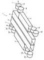
図2は、本発明に係わる電気自動車の床構造および駆動装置の実施の形態を模式的に示す斜視図である。床構造1は、図1に示されている参考例と同様のBBF構造であるので、同じ参照数字を付けて重複説明はしない。本実施の形態は、車輪の直径を従来のものに比較して小さくして、有効利用空間をさらに広く確保し、車輪の小径化により生じる車輪1輪当たりの耐荷重の低下を2輪に置き替えることにより補ったものである。すなわち、床構造1は比較的小径の4個の後輪13、14、13’、14’と、同様に比較的小径の4個の前輪15、16、15’、16’とで支えられている。本実施の形態によればインホイール式駆動装置7、7’が適用される。このインホイール式駆動装置7、7’は、前後輪13〜16’の8個のすべてに取り付けられている。しかしながら、図2には後輪13、13’のみにインホイール式駆動装置7、7’が取り付けられた例が示されている。なお、これらの車輪13〜16’は、サスペンション構造を形成するアーム類、バネ、ダンパー等を介して同様にセンタフレーム3、3’に取り付けられるが、その取り付け方の具体例は図3、4に示されている。
【0016】
図3は、懸架装20の第1の実施の形態を示したもので、(a)はその平面図、(b)はその正面図である。床構造1は、前述した参考例と同様であるので、同じ参照符号を付けて重複説明はしない。本実施の形態によると、床構造1はダブルウィッシュボーン式20、20’により懸架されている。すなわち、センタフレーム1、1’には水平方向の第1のサブフレーム21、21’と、垂直方向の第2のサブフレーム22、22’とが設けられている。そして、第1のサブフレーム21、21’と回転式電動機の外枠との間には、バネとダンパーからなる緩衝部材23、23’が設けられている。これにより、回転式電動機と床構造1は懸架装置を介して接続されている。第2のサブフレーム22、22’と車輪16、15、16、16’との間にはローアーアーム25、25’が設けられ、またセンタフレーム1、1’と車輪16、15、16、16’との間にはアッパーアーム26、26’が設けられている。
【0017】
図4は、懸架装の他の実施の形態を示す図で、その(a)は1対の車輪15、16のみを取り出したサスペンションの具体例を示した平面図、その(b)は正面図である。床構造1は、図1〜図3に示されている形態と同様であるので、同じ参照符号を付けて重複説明はしない。本実施の形態では、床構造1はボギー構造とダブルウィッシュボーン方式20の組み合わせからなるサスペンション30により2個の車輪16、15で支持されている。すなわち、本実施の形態のサスペンション30は、2個の車輪16、15を結合している剛体の構造材31と、この構造材31に、図4の(a)において水平方向の軸に対して回転自由に取り付けられている補助構造材32と、この補助構造材32に取り付けられている前述したダブルウィッシュボーン式20とから構成されている。なお、本実施の形態においては、回転式電動機の電機子が固定されている外枠は、図には示されていないが、構造材31に取り付けられている。
【0018】
次に、上記実施の形態の作用について説明する。本実施の形態による電気自動車も通常の乗用車と同様の運転方法で運転ができる。すなわち、進行方向を定めるためのレバーを例えば「前方向」の表示の側に倒し、アクセルペダルを踏むとセンタフレーム3、3’内に納められた電池B、B、…に蓄えられた電力が同じくサイドフレーム2、2、’内に納められた速度、トルク等の制御装置4、4’を通してインホイール式の駆動装置7、7’の中の回転式電動機に送り込まれ、回転式電動機が回転を始める。この回転力はインホイール式の駆動装置7、7’の中の減速歯車を通じて車輪のリム8、8’およびタイヤ9、9’に伝えられて電気自動車は発進する。停止の際にブレーキペダルを踏むと、まず、サイドフレーム2、2’内に納められた速度、トルク等の制御装置4、4’が働き、インホイール式の駆動装置7、7’の中の回転式電動機が発電機の働きをして車が減速するための機械力をもって発電を行い、ここで得られた電力が制御装置4、4’を通ってセンタフレーム3、3、’内に納められた電池に充電される。緊急時の車の停止、あるいは極めて低速な状態から車を停止させる際には、インホイール式の駆動装置あるいは他の車輪に納められている機械式ブレーキも同時に作動して、減速力を得る。
【0019】
本発明は上記の実施の形態に限定されることなく、色々な形で実施できる。例えば、上記実施の形態ではセンタフレーム3、3’は、2個になっているが、フレームの数を増やして軽量化された小型の電池を適用することもできる。また、サイドフレーム2、2’には、制御装置4、4’充電器5、車内用の冷暖房装置6等が収納されているが、これらの機器の全部が収納できない時はその一部が収納される。サスペンション20、30も上記実施の形態に限定されることなく、他の方式例えばストラット式、トレーリングアーム式等の他のサスペンション方式によっても実施できることは明らかである。さらには、本実施の形態は乗用の電気自動車に関するものであるが、本発明はトラック、バス等に広く応用できることも明らかである
【0020】
【発明の効果】
以上のように、本発明によると、自動車の床構造体は、軸方向に中空の複数個のフレームから構成され、それによって前記床構造体の剛性が高められていると共に、電池は前記床構造体に収納され、前輪および後輪は前後方向に連続して取り付けられた小径の2個の車輪からなり、その連続して設けられたそれぞれの車輪のホイール部分に前記回転式電動機が取り付けられ、前記回転式電動機と床構造体は懸架装置を介して接続されているので、次のような本発明に特有の効果が得られる。車室内の広い空間が有効に利用できる。しかも、電池は床構造体を構成している中空体内に収納されているので、電気自動車の重心の位置は低い。また、インホイール式の駆動装置を採用しているにも拘らず、バネ下重量の影響を最小限に押さえることができ、車の乗り心地も向上している。特に、回転式電動機の出力を8個の車輪に分散させることができ、1個当たりの回転式電動機の重量を軽減することができるので、車輪のロードホールディングを改善することができる。車輪の径を小さくしているので、車輪のためのホイールハウスが車室内部に突き出すことによる有効空間の減少を最小限度に抑えることができ、車室内の利用可能な空間をさらに拡大できるという効果が得られる。また、車の側面に取り付られるドアとホイールハウスとの干渉を著しく抑えることができるため、ドアを取り付ける位置の自由度が増し、その結果として乗員の乗り降りの容易性が増大し、ひいては車室内の空間をより有効に利用することが可能になるという効果も期待できる。
【図面の簡単な説明】
【図1】本発明の実施の形態と一部同じ構造を有する本発明の参考例を示す斜視図である。
【図2】本発明に係わる電気自動車の実施の形態を示す斜視図である。
【図3】懸架装置の実施の形態を示す図で、その(a)は平面図、その(b)は正面図である。
【図4】懸架装置の他の実施の形態を示す図で、その(a)は平面図、その(b)は正面図である。
【図5】電気自動車の駆動方式を模式的に示す図で、(a)〜(d)はそれぞれ異なる例を示す平面図である。
【符号の説明】
1 床構造
2、2’ サイドフレーム
3、3’ センタフレーム
4、4’ 制御装置
5 充電器
6 冷暖房装置
7、7’ インホイール式駆動装置
20、20’ サスペンション
30、30’ サスペンション[0001]
[Industrial application fields]
The present invention relates to aneight-wheel drive electric vehicle in which electric energy stored in a battery is supplied to a rotary electric motor for traveling, and wheels are driven by the rotary electric motor.
[0002]
[Prior art]
Compared to gasoline or diesel vehicles driven by an internal combustion engine that burns fossil fuels, electric vehicles whose wheels are driven by the electrical energy stored in the batteries are free from exhaust problems and are expected to spread from the standpoint of environmental measures. It is rare.
By the way, the weight of the battery, the mounting method, the driving method, and the like are the bottleneck in its spread. Therefore, various battery mounting methods, that is, battery storage methods, driving methods, and the like have been proposed.
[0003]
As a battery storage method, a method of storing in a space such as a hood of a vehicle body, a trunk room, or the like, or a battery storage method called a backbone method as described in JP-A-52-35023 has been proposed. That is, there is also known a backbone system in which a tunnel-shaped storage casing is provided in the front-rear direction of an automobile, and a battery is taken in and out from the front or rear of the storage casing.
Furthermore, Japanese Laid-Open Patent Publication No. 7-47842 proposes a frame-like floor structure in which the floor of the vehicle body is composed of a plurality of hollow frames having a substantially rectangular cross section, and batteries are accommodated in these frames. Has been. Hereinafter, this type of floor structure is referred to as a battery built-in frame (BBF structure) in this specification.
[0004]
On the other hand, as a driving method of an electric vehicle, four types of methods are known as shown in FIG. These methods are easily understood from the drawings and will not be described in detail. However, the method shown in FIG. 5A is called a conventional method, and the conventional internal combustion engine is replaced with a rotary electric motor. The system shown in (b) is a so-called no-transmission system in which the transmission is excluded from the system shown in (a), and the system in (c) is equipped with a rotary electric motor for the number of drive wheels. Defuresu method to remove the braking system type and shown (d), the is-wheel system incorporating a rotary electric motor on the inside of the vehiclewheel not on the vehicle body.
[0005]
A preferred form of the in-wheel system is proposed by Japanese Patent Laid-Open No. 7-81430. In this in-wheel system, a rotary electric motor for driving forms an integral structure with a reduction gear, a bearing brake and the like, and all or a part of this integral structure is housed in a wheel portion of a wheel.
[0006]
[Problems to be solved by the invention]
As described above, by adopting the BBF structure in the electric vehicle, a part of the problem of the battery housing method has been solved. In particular, in the BBF structure, there is an advantage that it is not necessary to provide a new space for battery storage and that the entire vehicle body can be reduced in weight because the battery storage container and the frame structure can be used together. In addition, since a heavy battery is stored under the floor, there is an advantage that the center of gravity of the vehicle body is low, and the stability and riding comfort of the automobile are improved. However, there are also points to be improved. For example, since the BBF requires that most of the floor surface be used in a planar shape, it may cause spatial interference with other components such as a driving device.
[0007]
In addition, by adopting an in-wheel system for the drive unit, there is no need to provide a special space for the drive unit on the vehicle body, resulting in a loss of energy transmission in the entire drive unit from the rotary motor to the tire. There is also an advantage that it disappears. However, the in-wheel method has a drawback that the load holding is deteriorated because of the so-called unsprung weight.
An object of the present invention is to provide an electric vehicle that eliminates the above-described conventional problems or disadvantages. Specifically, the effective use space of the vehicle body is wide, the entire vehicle body can be reduced in weight, and the center of gravity of the vehicle body is provided. The purpose is to provide an electric vehicle that is low in vehicle stability, ride comfort and road holding.
[0008]
[Means for Solving the Problems]
In order to achieve the above object, the present invention first applies both the BBF structure and the in-wheel method simultaneously in one vehicle. That is, the BBF structure is adopted to reduce the disadvantages of the in-wheel method, and the adoption of the in-wheel method is intended to reduce the disadvantages of the BBF structure to achieve the above object. By adopting both types in this way, an electric vehicle with a wide effective use space, a light weight of the entire vehicle body, a low center of gravity of the vehicle body, good vehicle stability and ride comfort, and good road holding can be obtained. . In particular, the rotary electric motor is configured to be mounted oneight wheels in order to actively reduce the deterioration of road holding.
As described above, by storing the battery in the frame of the BBF structure, the effective use space is widened, but in the electric vehicle, in addition to the battery and the drive device, a control device that controls the speed and torque of the rotary motor, Car-mounted chargers, air conditioners, etc. are also installed, but all or part of them arepreferably housed in the interior space of the floor structure in the same manner as batteries, so that the effective volume inside the vehicle body can be increased. It becomes possible.
[0009]
Also, if the wheel house protrudes greatly into the vehicle body as in a conventional automobile, the effective use space cannot be widened. This problem can be solved by making the wheel diameter smaller than that of the conventional one, for example, by half. When the diameter of the wheel is reduced in this way, the load resistance per wheel decreases and the vibration that the vehicle body receives from the road surface also increases. Therefore, thepresent invention is configured to suppress the vibration received by the vehicle body from the road surface as much as possible by replacing one wheel of the automobile with two small-diameter wheels arranged at the front and rear.
[0010]
That is, in order to achieve the above object, the invention according to
[0011]
Embodiment
Embodiments of the present invention will be described below. FIG. 1 is a schematic perspective view of a floor structure and a driving device of a passenger electric vehicle according toa reference example of thepresent invention having a part of the same structure as that of the embodiment of the present invention . As shown in the figure, the
[0012]
As described above, the
[0013]
According to thereference example , the
[0014]
Since the in-
[0015]
FIG. 2 is a perspective view schematically showingan embodiment of a floor structure of an electric vehicle and a driving apparatus according tothe present invention. Since the
[0016]
FIGS. 3A and 3B show the first embodiment of the
[0017]
4A and 4B are diagrams showing another embodiment of the suspension, in which FIG. 4A is a plan view showing a specific example of a suspension in which only a pair of
[0018]
Next, the operation of the above embodiment will be described. The electric vehicle according to the present embodiment can be driven by the same driving method as that of a normal passenger car. That is, when the lever for determining the traveling direction is tilted to the “forward” display side, for example, and the accelerator pedal is depressed, the electric power stored in the batteries B, B,. Similarly, the speed and
[0019]
The present invention is not limited to the above embodiment, and can be implemented in various forms. For example, although the number of center frames 3 and 3 ′ is two in the above embodiment, a small battery that is lightened by increasing the number of frames can be applied. The side frames 2 and 2 'contain a
【The invention's effect】
As described above, according to the present invention, the floor structure of an automobile is composed of a plurality of frames that are hollow in the axial direction, whereby the rigidity of the floor structure is enhanced, and the battery has the floor structure. Stored in the body, the front wheel and the rear wheel are composed of twosmall-diameter wheels continuously attached in the front-rear direction, and the rotary electric motor is attached to the wheel portion ofeach continuously provided wheel, Since the rotary electric motor and the floor structure are connected via a suspension device, the following effects specific to the present invention can be obtained. A wide space in the passenger compartment can be used effectively. And since the battery is accommodated in the hollow body which comprises the floor structure, the position of the gravity center of an electric vehicle is low.In addition , despite the use of an in-wheel drive device, the influence of unsprung weight can be minimized and the ride comfort of the vehicle is improved. In particular, the output of the rotary motor can be distributed toeight wheels, and the weight of the rotary motor per unit can be reduced, so that the load holding of the wheels can be improved.Since the small diameter of the wheels, the reduction of the effective space due to protrude inside the wheel house cabin for the wheel can be suppressed to a minimum, the effect of being able to further expand the available space in the passenger compartment Is obtained. Moreover, since it is possible to suppress significantlythe interference between the door and thewheel house is Installing the side of the car, increasing the degree of freedom of a position for attaching the door, the ease of passengers getting on and off is increased as a result, hence the passenger compartment The effect that it becomes possible to use the space of this more effectively can also be expected.
[Brief description of the drawings]
FIG. 1 is a perspective view showinga reference example of thepresent invention having a part of the same structure as that of an embodiment of the present invention .
FIG. 2 is a perspective view showing an embodiment of an electric vehicle according to the present invention.
FIG. 3 is a diagram showing an embodiment of a suspension device, in which (a) is a plan view and (b) is a front view.
FIG. 4 is a view showing another embodiment of the suspension device, in which (a) is a plan view and (b) is a front view.
FIGS. 5A and 5B are diagrams schematically illustrating a driving method of an electric vehicle, and FIGS. 5A to 5D are plan views illustrating different examples. FIGS.
[Explanation of symbols]
DESCRIPTION OF
Claims (1)
Translated fromJapanese前記自動車の床構造体は、軸方向に中空の複数個のフレームから構成され、それによって前記床構造体の剛性が高められていると共に、電池は前記床構造体に収納され、
前輪および後輪は前後方向に連続して取り付けられた小径の2個の車輪からなり、その連続して設けられたそれぞれの車輪のホイール部分に前記回転式電動機が取り付けられ、前記回転式電動機と床構造体は懸架装置を介して接続されていることを特徴とする8輪駆動の電気自動車。In an electric vehicle in which electric energy stored in a battery is supplied to a rotary electric motor of an in-wheel type driving device, and wheels are driven by the rotary electric motor.
The automobile floor structure is composed of a plurality of axially hollow frames, whereby the rigidity of the floor structure is enhanced, and the battery is housed in the floor structure,
The front wheel and the rear wheel are composed of two small-diameter wheels continuously attached in the front-rear direction, and the rotary electric motor is attached to a wheel portion of each of the continuously provided wheels. The floor structure is connected via a suspension device, and is an 8-wheel driveelectric vehicle .
Priority Applications (1)
| Application Number | Priority Date | Filing Date | Title |
|---|---|---|---|
| JP2003136739AJP3840461B2 (en) | 2003-05-15 | 2003-05-15 | 8-wheel drive electric vehicle |
Applications Claiming Priority (1)
| Application Number | Priority Date | Filing Date | Title |
|---|---|---|---|
| JP2003136739AJP3840461B2 (en) | 2003-05-15 | 2003-05-15 | 8-wheel drive electric vehicle |
Related Parent Applications (1)
| Application Number | Title | Priority Date | Filing Date |
|---|---|---|---|
| JP9103981ADivisionJPH10278596A (en) | 1997-04-08 | 1997-04-08 | Electric vehicle |
Publications (2)
| Publication Number | Publication Date |
|---|---|
| JP2004001737A JP2004001737A (en) | 2004-01-08 |
| JP3840461B2true JP3840461B2 (en) | 2006-11-01 |
Family
ID=30438089
Family Applications (1)
| Application Number | Title | Priority Date | Filing Date |
|---|---|---|---|
| JP2003136739AExpired - Fee RelatedJP3840461B2 (en) | 2003-05-15 | 2003-05-15 | 8-wheel drive electric vehicle |
Country Status (1)
| Country | Link |
|---|---|
| JP (1) | JP3840461B2 (en) |
Cited By (1)
| Publication number | Priority date | Publication date | Assignee | Title |
|---|---|---|---|---|
| CN111183088A (en)* | 2018-12-05 | 2020-05-19 | 翼科株式会社 | Chassis for electric automobile and electric automobile |
Families Citing this family (10)
| Publication number | Priority date | Publication date | Assignee | Title |
|---|---|---|---|---|
| JP4565227B2 (en)* | 2004-04-01 | 2010-10-20 | 株式会社クリーンクラフト | Electric bus body structure |
| JP2007181293A (en)* | 2005-12-27 | 2007-07-12 | Toyota Motor Corp | Vehicle drive device |
| JP5052972B2 (en)* | 2007-06-26 | 2012-10-17 | 株式会社クリーンクラフト | Electric vehicle suspension system |
| JP5335206B2 (en)* | 2007-06-27 | 2013-11-06 | 株式会社クリーンクラフト | Electric vehicle traveling device |
| US7837220B2 (en)* | 2008-07-10 | 2010-11-23 | Caterpillar Inc | Tandem wheel arrangement |
| CN108045188B (en)* | 2017-12-15 | 2024-02-20 | 广州市远能物流自动化设备科技有限公司 | Parallel arm type driving structure |
| JP6516233B1 (en)* | 2018-12-05 | 2019-05-22 | 株式会社e−Gle | Chassis for electric vehicles and electric vehicles |
| JP6749659B2 (en)* | 2019-04-05 | 2020-09-02 | 株式会社e−Gle | Chassis for electric vehicles and electric vehicles |
| GB2609652B (en)* | 2021-08-12 | 2024-01-31 | Protean Electric Ltd | A vehicle |
| CN116654094A (en)* | 2023-06-30 | 2023-08-29 | 三亚学院 | Frame body, box girder type frame assembly and vehicle |
Family Cites Families (12)
| Publication number | Priority date | Publication date | Assignee | Title |
|---|---|---|---|---|
| GB1556161A (en)* | 1975-09-10 | 1979-11-21 | Lucas Industries Ltd | Electrically driven vehicles |
| JPS55107406U (en)* | 1979-01-24 | 1980-07-28 | ||
| JPS5649640U (en)* | 1979-09-25 | 1981-05-01 | ||
| JPS58115477U (en)* | 1982-02-01 | 1983-08-06 | 有限会社河島農具製作所 | 6 wheel or 8 wheel drive vehicle |
| JPS63207706A (en)* | 1987-02-21 | 1988-08-29 | Okano Kosan Kk | Off-road running vehicle |
| FR2631902B1 (en)* | 1988-05-31 | 1990-09-07 | Andruet Jean Claude | AUTOMOTIVE VEHICLE WITH ELECTRIC PROPULSION |
| JPH0388979U (en)* | 1989-12-28 | 1991-09-11 | ||
| JP3345632B2 (en)* | 1993-02-23 | 2002-11-18 | 国立環境研究所長 | Body for electric vehicles |
| FR2708552B1 (en)* | 1993-08-06 | 1995-09-29 | Betka Mohamed | Modular go-kart chassis in length and number of front directional wheels. |
| JP2545733B2 (en)* | 1993-09-17 | 1996-10-23 | 環境庁国立環境研究所長 | Electric vehicle drive |
| JP3406074B2 (en)* | 1994-08-23 | 2003-05-12 | 国立環境研究所長 | Chassis frame for electric vehicles |
| JPH10278596A (en)* | 1997-04-08 | 1998-10-20 | Hiroshi Shimizu | Electric vehicle |
- 2003
- 2003-05-15JPJP2003136739Apatent/JP3840461B2/ennot_activeExpired - Fee Related
Cited By (2)
| Publication number | Priority date | Publication date | Assignee | Title |
|---|---|---|---|---|
| CN111183088A (en)* | 2018-12-05 | 2020-05-19 | 翼科株式会社 | Chassis for electric automobile and electric automobile |
| CN111183088B (en)* | 2018-12-05 | 2021-01-12 | 翼科株式会社 | Chassis for electric automobile and electric automobile |
Also Published As
| Publication number | Publication date |
|---|---|
| JP2004001737A (en) | 2004-01-08 |
Similar Documents
| Publication | Publication Date | Title |
|---|---|---|
| JPH10278596A (en) | Electric vehicle | |
| US7118119B2 (en) | Vehicle with electric motors | |
| CN103009980B (en) | Battery support structure for vehicle | |
| CN114074711B (en) | Electric vehicle with axle module | |
| JP5728019B2 (en) | Automobile | |
| TWI568619B (en) | Electric vehicle | |
| US20130240273A1 (en) | Electrically Driven Axle of a Two-Track Vehicle | |
| US3989119A (en) | Public service vehicle | |
| JP3840461B2 (en) | 8-wheel drive electric vehicle | |
| JP5413102B2 (en) | Front structure of an electric vehicle equipped with an engine | |
| JP7049584B2 (en) | Vehicle drive | |
| JP2001097048A (en) | Body structure of electric vehicle | |
| JP2002187577A (en) | Electric car chassis frame | |
| JP3369546B2 (en) | Electric car | |
| JP5418117B2 (en) | Front structure of an electric vehicle equipped with an engine | |
| JP3666543B2 (en) | Electric vehicle motor mounting structure | |
| CN211335502U (en) | A low-floor chassis platform with integrated in-wheel motors | |
| JP2002186116A (en) | Wireless LAN system in a car for electric vehicles | |
| WO2019207879A1 (en) | Electric vehicle | |
| KR101610437B1 (en) | Vehicle having joint connected body | |
| JPH11115516A (en) | Electric automobile | |
| JPH06156314A (en) | Two passenger automobile | |
| KR20130068961A (en) | Electronic vehicle | |
| CN218907368U (en) | A pure electric heavy-duty truck sanitation chassis with a battery flat electric drive axle | |
| CN216034643U (en) | Automobile |
Legal Events
| Date | Code | Title | Description |
|---|---|---|---|
| A621 | Written request for application examination | Free format text:JAPANESE INTERMEDIATE CODE: A621 Effective date:20030515 | |
| A977 | Report on retrieval | Free format text:JAPANESE INTERMEDIATE CODE: A971007 Effective date:20050622 | |
| A131 | Notification of reasons for refusal | Free format text:JAPANESE INTERMEDIATE CODE: A131 Effective date:20050705 | |
| A521 | Written amendment | Free format text:JAPANESE INTERMEDIATE CODE: A523 Effective date:20050902 | |
| A131 | Notification of reasons for refusal | Free format text:JAPANESE INTERMEDIATE CODE: A131 Effective date:20060404 | |
| A521 | Written amendment | Free format text:JAPANESE INTERMEDIATE CODE: A523 Effective date:20060406 | |
| TRDD | Decision of grant or rejection written | ||
| A01 | Written decision to grant a patent or to grant a registration (utility model) | Free format text:JAPANESE INTERMEDIATE CODE: A01 Effective date:20060801 | |
| A61 | First payment of annual fees (during grant procedure) | Free format text:JAPANESE INTERMEDIATE CODE: A61 Effective date:20060807 | |
| R150 | Certificate of patent or registration of utility model | Free format text:JAPANESE INTERMEDIATE CODE: R150 | |
| A521 | Written amendment | Free format text:JAPANESE INTERMEDIATE CODE: A523 Effective date:20050902 | |
| FPAY | Renewal fee payment (event date is renewal date of database) | Free format text:PAYMENT UNTIL: 20090811 Year of fee payment:3 | |
| S111 | Request for change of ownership or part of ownership | Free format text:JAPANESE INTERMEDIATE CODE: R313113 | |
| FPAY | Renewal fee payment (event date is renewal date of database) | Free format text:PAYMENT UNTIL: 20090811 Year of fee payment:3 | |
| R360 | Written notification for declining of transfer of rights | Free format text:JAPANESE INTERMEDIATE CODE: R360 | |
| FPAY | Renewal fee payment (event date is renewal date of database) | Free format text:PAYMENT UNTIL: 20090811 Year of fee payment:3 | |
| S111 | Request for change of ownership or part of ownership | Free format text:JAPANESE INTERMEDIATE CODE: R313113 | |
| R360 | Written notification for declining of transfer of rights | Free format text:JAPANESE INTERMEDIATE CODE: R360 | |
| R371 | Transfer withdrawn | Free format text:JAPANESE INTERMEDIATE CODE: R371 | |
| FPAY | Renewal fee payment (event date is renewal date of database) | Free format text:PAYMENT UNTIL: 20100811 Year of fee payment:4 | |
| R350 | Written notification of registration of transfer | Free format text:JAPANESE INTERMEDIATE CODE: R350 | |
| FPAY | Renewal fee payment (event date is renewal date of database) | Free format text:PAYMENT UNTIL: 20100811 Year of fee payment:4 | |
| FPAY | Renewal fee payment (event date is renewal date of database) | Free format text:PAYMENT UNTIL: 20110811 Year of fee payment:5 | |
| FPAY | Renewal fee payment (event date is renewal date of database) | Free format text:PAYMENT UNTIL: 20110811 Year of fee payment:5 | |
| FPAY | Renewal fee payment (event date is renewal date of database) | Free format text:PAYMENT UNTIL: 20150811 Year of fee payment:9 | |
| LAPS | Cancellation because of no payment of annual fees |