JP3840153B2 - Recording device - Google Patents
Recording deviceDownload PDFInfo
- Publication number
- JP3840153B2 JP3840153B2JP2002201651AJP2002201651AJP3840153B2JP 3840153 B2JP3840153 B2JP 3840153B2JP 2002201651 AJP2002201651 AJP 2002201651AJP 2002201651 AJP2002201651 AJP 2002201651AJP 3840153 B2JP3840153 B2JP 3840153B2
- Authority
- JP
- Japan
- Prior art keywords
- recording
- tray
- carriage
- roller
- head
- Prior art date
- Legal status (The legal status is an assumption and is not a legal conclusion. Google has not performed a legal analysis and makes no representation as to the accuracy of the status listed.)
- Expired - Fee Related
Links
Images


Classifications
- B—PERFORMING OPERATIONS; TRANSPORTING
- B41—PRINTING; LINING MACHINES; TYPEWRITERS; STAMPS
- B41J—TYPEWRITERS; SELECTIVE PRINTING MECHANISMS, i.e. MECHANISMS PRINTING OTHERWISE THAN FROM A FORME; CORRECTION OF TYPOGRAPHICAL ERRORS
- B41J11/00—Devices or arrangements of selective printing mechanisms, e.g. ink-jet printers or thermal printers, for supporting or handling copy material in sheet or web form
- B41J11/008—Controlling printhead for accurately positioning print image on printing material, e.g. with the intention to control the width of margins
- B—PERFORMING OPERATIONS; TRANSPORTING
- B41—PRINTING; LINING MACHINES; TYPEWRITERS; STAMPS
- B41J—TYPEWRITERS; SELECTIVE PRINTING MECHANISMS, i.e. MECHANISMS PRINTING OTHERWISE THAN FROM A FORME; CORRECTION OF TYPOGRAPHICAL ERRORS
- B41J11/00—Devices or arrangements of selective printing mechanisms, e.g. ink-jet printers or thermal printers, for supporting or handling copy material in sheet or web form
- B41J11/0095—Detecting means for copy material, e.g. for detecting or sensing presence of copy material or its leading or trailing end
- B—PERFORMING OPERATIONS; TRANSPORTING
- B41—PRINTING; LINING MACHINES; TYPEWRITERS; STAMPS
- B41J—TYPEWRITERS; SELECTIVE PRINTING MECHANISMS, i.e. MECHANISMS PRINTING OTHERWISE THAN FROM A FORME; CORRECTION OF TYPOGRAPHICAL ERRORS
- B41J19/00—Character- or line-spacing mechanisms
- B41J19/18—Character-spacing or back-spacing mechanisms; Carriage return or release devices therefor
- B41J19/20—Positive-feed character-spacing mechanisms
- B41J19/202—Drive control means for carriage movement
- B—PERFORMING OPERATIONS; TRANSPORTING
- B41—PRINTING; LINING MACHINES; TYPEWRITERS; STAMPS
- B41J—TYPEWRITERS; SELECTIVE PRINTING MECHANISMS, i.e. MECHANISMS PRINTING OTHERWISE THAN FROM A FORME; CORRECTION OF TYPOGRAPHICAL ERRORS
- B41J3/00—Typewriters or selective printing or marking mechanisms characterised by the purpose for which they are constructed
- B41J3/407—Typewriters or selective printing or marking mechanisms characterised by the purpose for which they are constructed for marking on special material
- B41J3/4071—Printing on disk-shaped media, e.g. CDs
Landscapes
- Ink Jet (AREA)
- Handling Of Cut Paper (AREA)
- Dot-Matrix Printers And Others (AREA)
Description
Translated fromJapanese【0001】
【産業上の利用分野】
本発明は、キャリッジに搭載した記録ヘッドにより被記録材に記録を行う記録装置に関する。
【0002】
【従来の技術】
従来より、プリンタや画像形成装置等の記録装置によって記録される被記録材として様々なものが提案されている。その中に、CD−RやDVDやカードのように小型で厚みのある被記録材がある(以下、まとめてCD(コンパクトディスク)と称する)。現行の汎用記録装置においては、CD等の被記録材に記録する場合に単票用紙の搬送経路を使用すると、CDの剛性が高いことに起因して、搬送性が悪くなったり、傷が発生したり、搬送ローラ間の距離の関係で搬送不能になるなどの不具合が発生しやすい。そこで、CD等の小型で厚みのある被記録材を搬送する場合は、画像被記録材を搭載するためのトレイを使用し、単票用紙の搬送経路とは異なる経路を通して搬送することが行われている。
【0003】
前記トレイを使用する場合は、該トレイの厚みが一般的な単票用紙より厚いことから、搬送ローラ対への挿入、搬送ローラ対による挟持、記録手段(記録ヘッド)と被記録材との間の適正ギャップの確保などに十分な配慮をする必要がある。そのための1つの手段として、記録装置に操作レバーを設け、該操作レバーの動きに連動して搬送ローラ等の搬送部材の押圧を解除する方法がある。この場合、ユーザーは、トレイを所定位置まで挿入して位置を合わせたところで、前記操作レバーを操作して再び搬送部材を押圧状態にセットする。
さらに、操作レバーによって、記録ヘッドを搭載しているキャリッジを上昇させ、ギャップ(被記録材との間の紙間距離)の確保を行っている。
【0004】
また、CD等の被記録材に記録(印刷)を行う場合には、特にCD等の被記録材の位置検出を行わずに記録を行う方法、あるいは、キャリッジ上に搭載されたセンサによってCDの記録範囲の白色部位の位置を直接的に検出して記録を行う方法が採用されている。しかしながら、被記録材の位置検出を行わない場合は、記録した画像がCD等の被記録材に対してずれてしまうので、ユーザーがパソコン上のアプリケーション等で記録装置を調整するなどの作業が必要である。そのため、最近では、キャリッジ上に搭載したセンサ(トレイ位置検出センサ等)により被記録材の位置を検出して記録する方法が多用されている。
【0005】
【発明が解決しようとする課題】
しかしながら、このようにキャリッジ上に搭載したセンサでCD等の被記録材の位置を検出する方法では、センサと記録手段である記録ヘッドとの位置が正確でないと正しい位置に記録することができない。従って、センサの取り付け精度も向上させる必要があり、そのために部品の形状寸法の精度向上や緻密な組立て方法の採用などが必要となり、コストアップの要因となっている。
本発明はこのような技術的課題に鑑みてなされたものであり、本発明の目的は、簡単な構成で、キャリッジに配された検出センサと記録ヘッドとのずれ量を算出することができ、被記録材の正確な位置に記録することができる記録装置を提供することである。
【0006】
【課題を解決するための手段】
請求項1の発明は、上記目的を達成するため、被記録材に記録を行う記録ヘッドまたは調整用センサを備える調整用ヘッドを搭載して移動するためのキャリッジと、前記キャリッジに配され、被記録材の位置を検出するための検出センサと、を備え、前記キャリッジに前記調整用ヘッドを搭載して前記調整用センサと前記検出センサで同一のマークを読み取り、前記調整用センサと前記検出センサとの相対位置のずれ量から記録ヘッドを搭載して記録を行うときの補正値を算出することを特徴とする。
【0010】
【発明の実施の形態】
以下、図面を参照して本発明の実施の形態を具体的に説明する。なお、各図面を通して同一符号は同一又は対応部分を示すものである。
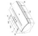
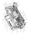
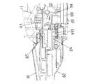
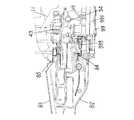
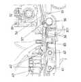
図1は本発明を適用した記録装置の一実施例を示す斜視図であり、図2は図1の記録装置で給紙トレイ及び排紙トレイを開いた状態を示す斜視図であり、図3は図1の記録装置の内部機構を右前方から見て示す斜視図であり、図4は図3の記録装置の内部機構を左前方から見て示す斜視図であり、図5は図3の記録装置の縦断面図であり、図6は図1の記録装置にCD搬送部8を装着する前後の状態を示す斜視図であり、図7は図1の記録装置に装着可能なCD搬送部8を示す斜視図である。
また、図8〜図19は本発明を適用した記録装置の一実施例におけるCD印刷のための構成及び動作を説明するための図面である。
図1〜図5において、本実施例に係る記録装置1は、給紙部2、送紙部3、排紙部4、キャリッジ部(記録手段移動手段)5、回復機構部(クリーニング部)6、記録手段(記録ヘッド)7、CD搬送部8、及び電気部9を備えている。以下にこれらの各部について項目に分けて概略を順次述べていく。
【0011】
(A)給紙部
給紙部2は、シート材Pを積載する圧板21、シート材Pを給紙する給紙ローラ28、シート材Pを分離する分離ローラ241、シート材Pを積載位置に戻すための戻しレバー22などをベース20に取り付けて構成されている(図5)。積載されたシート材Pを保持するための給紙トレイ26は前記ベース20または記録装置の外装に取り付けられている。給紙トレイ26は、図2に示すように多段式であり、使用時には引出して使用される。
【0012】
前記給紙ローラ28は断面円弧の棒状をしており、該給紙ローラ28には用紙基準よりに1つの分離ローラゴム(給紙ローラゴム)281が設けられている。このような給紙ローラ28によってシート材の給紙(送り出し)が行われる。前記給紙ローラ28の駆動は、給紙部2に設けられた給紙モータ273から駆動伝達ギア271及び遊星ギア272を介して伝達される駆動力によって行われる。前記圧板21には可動サイドガイド23が移動可能に設けられ、シート材Pの積載位置を規制している。圧板21はベース20に結合された回転軸を中心に回転可能で、圧板バネ212により給紙ローラ28に向けて付勢されている。給紙ローラ28と対向する圧板21の部位には、積載された複数枚のシート材Pのうちの最上位の数枚の重送を防止するために、人工皮等の摩擦係数の大きい材質からなる分離シート213が設けられている。圧板21は、圧板カム214によって、給紙ローラ28に対して当接、離間できるように構成されている。
【0013】
さらに、ベース20には、シート材Pを一枚ずつ分離するための分離ローラ241が取り付けられた分離ローラホルダ24が、該ベース20に設けられた回転軸を中心に回転可能で、かつ分離ローラばね242により給紙ローラ28に付勢された状態で取り付けられている。分離ローラ241には分離ローラクラッチ(クラッチばね)243が取り付けられており、該分離ローラ241に所定以上の負荷がかかると、該分離ローラ241が取り付けられた部分が回転できるように構成されている。分離ローラ241は、分離ローラリリースシャフト244とコントロールカム25とによって、給紙ローラ28に対して当接、離間できるように構成されている。これらの圧板21、戻しレバー22、分離ローラ241の位置はASFセンサ29によって検知されている。
また、シート材Pを積載位置に戻すための戻しレバー22は、ベース20に回転可能に取り付けられ、解除方向に戻しレバーバネ221で付勢されている。この戻しレバー22は、シート材Pを積載位置に戻す時は、前記コントロールカム25によって回転するように構成されている。
【0014】
以上の構成を用いて給紙する状態を以下に説明する。
通常の待機状態では、圧板21は圧板カム214でリリースされ、分離ローラ241はコントロールカム25でリリースされ、さらに、戻しレバー22は、シート材Pを積載位置に戻すとともに、積載時にシート材Pが奥に入らないように積載口を塞ぐような積載位置に設けられている。
この状態から、給紙が始まると、モータ駆動によって、まず、分離ローラ241が給紙ローラ28に当接する。そして、戻しレバー22がリリースされ、圧板21が給紙ローラ28に当接する。この状態で、シート材Pの給紙が開始される。シート材Pはベース20に設けられた前段分離部201で制限され、シート材Pの所定枚数のみが給紙ローラ28と分離ローラ241とで形成されるニップ部に送られる。送られたシート材Pはこのニップ部で分離され、最上位のシート材Pのみが搬送(給紙)される。
【0015】
シート材Pが後述の搬送ローラ36及びピンチローラ37から成る搬送ローラ対まで到達すると、圧板21は圧板カム214によって、分離ローラ28はコントロールカム25によって、それぞれリリースされる。また、戻しレバー22はコントロールカム25によって積載位置に戻る。この時、給紙ローラ28と分離ローラ241との間のニップ部に到達していたシート材Pを積載位置まで戻すことができる。
【0016】
(B)送紙部
曲げ起こした板金からなるシャーシ11に送紙部3が取り付けられている。送紙部3はシート材Pを搬送する搬送ローラ36とPEセンサ32を有している。搬送ローラ36は金属軸の表面にセラミックの微小粒をコーティングした構成であり、両軸の金属部分を軸受38で受けることでシャーシ11に取り付けられている。搬送ローラ36に回転時の負荷を与えることで安定した搬送を行うために、軸受38と搬送ローラ36との間に搬送ローラテンションばね381が設けられ、該搬送ローラ36を付勢することで所定の負荷を与えるように構成されている。
【0017】
搬送ローラ36には、従動回転する複数のピンチローラ37が当接して設けられている。ピンチローラ37は、ピンチローラホルダ30に保持され、ピンチロラーばね31で付勢することでピンチローラ37が搬送ローラ36に圧接され、シート材Pの搬送力を生み出している。ここで、ピンチローラホルダ30は、その回転軸がシャーシ11の軸受に取り付けられ、該回転軸を中心に回動する。さらに、シート材Pが搬送されてくる送紙部3の入口には、シート材Pをガイドするペーパーガイドフラッパー33及びプラテン34が配設されている。また、ピンチローラホルダ30には、シート材Pの先端及び後端の検出をPEセンサ32に伝えるためのPEセンサレバー321が設けられている。プラテン34は、シャーシ11に取り付けられて位置決めされている。ペーパーガイドフラッパー33は、搬送ローラ36と嵌合し、摺動する軸受部331を中心に回転可能であり、シャーシ11に当接することで位置決めされる。
【0018】
また、プラテン34の紙基準側にはシート材Pの端部を覆う紙押さえ341が設けられている。これによって、端部か変形したシート材Pやカールしたシート材Pの場合でも、該シート材Pの端部が浮き上がってキャリッジ50もしくは記録ヘッド7と干渉することがないようにしている。さらに、搬送ローラ36のシート材搬送方向における下流側には、画像情報に基づいて画像を形成する記録ヘッド7が設けられている。
上記構成において、送紙部3に送られたシート材Pは、ピンチローラホルダ30及びペーパーガイドフラッパー33に案内されて、搬送ローラ36とピンチローラ37とのローラ対へ送り込まれる。この時、PEセンサレバー321により搬送されてきたシート材Pの先端を検知し、これによりシート材Pの記録位置(印刷位置、画像形成位置)を求めている。また、シート材Pは、搬送モータ35によりローラ対36、37が回転することで、プラテン34上を搬送される。プラテン34上には、搬送基準面になるリブが形成されている。このリブは、記録ヘッド7とのギャップを管理するとともに、後述の排紙部と合わせて、シート材Pの浪打を制御することにより該浪打が大きくならないようにするためのものである。
【0019】
搬送ローラ36の駆動は、DCモータからなる搬送モータ35の回転力をタイミングベルトで搬送ローラ36の軸上に設けたプーリ361に伝達することで行われる。
また、搬送ローラ36の軸上には、該搬送ローラ36による搬送量を検出するためのコードホイール362が設けられている。このコードホイール362には150〜300lpiのピッチでマーキングが形成されている。そして、前記コードホイール362に隣接する位置のシャーシ11の部位には、前記マーキングを読み取るためのエンコーダーセンサ39が取り付けられている。
なお、前記記録手段(記録ヘッド)7としては、インクジェット記録ヘッドが使用されている。この記録ヘッド7には、各インク色ごとに別体のインクタンクが交換可能に装着されるようになっている。また、この記録ヘッド7は、記録データに基づいてヒータ(発熱素子)等によりインクに熱を与えることが可能となっている。そして、この熱によりインクが膜沸騰し、この膜沸騰による気泡の成長または収縮によって生じる圧力変化によって記録ヘッド7の吐出口からインクを吐出し、吐出されたインク滴によってシート材P上に画像を形成するように構成されている。
【0020】
(C)キャリッジ部
キャリッジ部5は、記録手段としての記録ヘッド7を被記録材搬送方向と交差する方向に移動させるための記録手段移動手段としてのキャリッジ50を有している。このキャリッジ50は、シート材Pの搬送方向と直交する方向に設置されたガイドシャフト52及びガイドレール111によって主走査方向に往復移動可能に案内支持されている。前記ガイドレール111は、キャリッジ50の後端を保持することで、記録ヘッド7とシート材Pとの隙間(紙間)を適正値に維持する機能も有している。なお、前記ガイドシャフト52はシャーシ11に取り付けられており、前記ガイドレール111はシャーシ11と一体に形成されている。前記ガイドレール111のキャリッジ50との摺動側には、SUS等の薄板の摺動シート53が張設され、摺動音の低減が図られている。
【0021】
また、キャリッジ部5(キャリッジ50)は、シャーシ11に取り付けられたキャリッジモータ54によりタイミングベルト541を介して駆動される。このタイミングベルト541はアイドルプーリ542によって張設支持されている。タイミングベルト541とキャリッジ50とはゴム等からなるダンパー55を介して結合されており、キャリッジモータ54等の振動を減衰することで、画像ムラ等を低減している。そして、キャリッジ50の位置を検出するために、150〜300lpiのピッチでマーキングを形成したコードストリップ561がタイミングベルト541と平行に設けられている。さらに、該コードストリップ561を読み取るためのエンコーダーセンサ56が、キャリッジ50に搭載したキャリッジ基板92に設けられている。このキャリッジ基板92には、記録ヘッド7と電気的な接続を行うためのコンタクト921も設けられている。また、キャリッジ50には、電気部(電気基板)9から記録ヘッド7へヘッド信号を伝えるためのフレキシブル基板57が設けられている。
【0022】
記録手段としての記録ヘッド7をキャリッジ50に固定するために、該キャリッジ50には位置決めのための突き当て部501並びに記録ヘッド7を押し付けて固定するための押圧手段(ヘッド押圧手段)511が設けられている。この押圧手段511はヘッドセットレバー51に搭載されており、該ヘッドセットレバー51を回転支点を中心に回動して記録ヘッド7をセットする際に、該記録ヘッド7に押し付け力が作用する構成になっている。
また、ガイドシャフト52の両端には偏心カムR(右側の偏心カム)521及び偏心カムL(左側の偏心カム)522が設けられており、キャリッジ昇降モータ58の駆動により、ギア列581を介して偏心カム521まで駆動を伝達することによってガイドシャフト52を上下に昇降させることができる。このガイドシャフト52の昇降に応じてキャリッジ50も同様に昇降させられ、厚みの異なるシート材Pに対しても最適なギャップを形成することができる。
【0023】
さらに、キャリッジ50には、CD−R等の小型で厚肉の被記録材の表示部に記録(印刷)するためのCD印刷用トレイ83の位置検出用のマーク834を検出するための反射型光センサからなるトレイ位置検出センサ59が取り付けられている。このトレイ位置検出センサ59は、発光素子より発光し、その反射光を受光することでトレイ83の位置を検出することができる。
上記構成において、シート材Pに画像を形成する時は、ローラ対(搬送ローラとピンチローラ)36、37によって、記録する行の位置(シート材Pの搬送方向の位置)にシート材Pを搬送するとともに、キャリッジモータ54によりキャリッジ50を記録(画像形成)位置(シート材Pの搬送方向と垂直な方向の位置)に移動させ、記録ヘッド7を記録位置(画像形成位置)に対向させる。その後、電気部(電気基板)9からの信号により記録ヘッド7がシート材Pに向けてインクを吐出することにより、記録(画像形成)が行われる。
【0024】
(D)排紙部
排紙部4は、2本の排紙ローラ40、41と、該排紙ローラ40、41に所定圧で当接することで従動回転可能な拍車42と、搬送ローラ36の駆動を排紙ローラ40、41伝達するためのギア列と、を備えている(図5)。
排紙ローラ40、41はプラテン34に取り付けられている。搬送方向上流側の排紙ローラ40は金属軸に複数のゴム部(排紙ローラゴム)401を設けて構成されている。排紙ローラ40は、搬送ローラ36からの駆動がアイドラギアを介して伝達されることにより駆動される。排紙ローラ41は樹脂の軸に複数のエラストマー等の弾性体411を取り付けた構成になっている。排紙ローラ41は、排紙ローラ40からアイドラギアを介して駆動を伝達されることにより駆動される。
【0025】
拍車42としては、例えば、SUSの薄板で周囲に凸形状を複数設けたものを樹脂部と一体成型したものが使用される。このような拍車42は拍車ホルダ43に取り付けられている。本実施例では、コイルばねを棒状に設けた拍車ばね44によって、拍車42の拍車ホルダー43への取り付けと排紙ローラ40、41への圧接等が行われている。拍車42には、主にシート材Pの搬送力を生み出すものと、主に記録される時のシート材Pの浮き上がりを阻止するものとがある。搬送力を生み出す拍車は、排紙ローラ40、41のゴム部(排紙ローラゴム部、弾性体部)に対応する位置に配設されている。一方、シート材Pの浮き上がりを阻止するための拍車は、排紙ローラ40、41のゴム部401が無い位置(ゴム部401とゴム部401との間など)に配設されている。
【0026】
前記排紙ローラ40、41の間には紙端サポート45が設けられている。この紙端サポート45は、シート材Pの両端を持ち上げ、排紙ローラ40、41の先でシート材Pを保持することにより、先出のシート材P上の画像記録部を擦ることによる記録画像のダメージ又は品位低下を防止するためのものである。前記紙端サポート45は、先端にコロ451が設けられた樹脂部材を紙端サポートばね452によって付勢することで、該コロ451を所定の押圧力でシート材Pに押し付けることにより、該シート材Pの両端を持ち上げて該シート材Pの腰を作ることで該シート材Pを保持できるように構成されている。
【0027】
以上の構成によって、キャリッジ部5で記録(画像形成)されたシート材Pは、排紙ローラ41と拍車42とのニップ部に挟まれ、搬送されて排紙トレイ46に排出される。排紙トレイ46は、複数の部材から成る分割構造を有し、記録装置の下ケース99の下部に収納できる構成になっている。この排紙トレイ46は、使用時には引出して使用する。図示の排紙トレイ46においては、その先端に向けて高さが高くなるように形成され、その両側端縁も高さが高く形成されており、それによって、排出されたシート材Pの積載性向上並びに該シート材Pの記録面の擦れ防止が図られている(図2)。
【0028】
(E)回復機構部(クリ−ニング部)
回復機構部(クリーニング部)6は、記録ヘッド7の吐出性能の維持回復のための吸引回復処理(クリーニング操作)を行うためのポンプ(負圧発生源としての吸引ポンプ等)60と、記録ヘッド7の吐出口面の保護及び乾燥防止を行うためのキャップ61と、記録ヘッド7の吐出口面の吐出口周辺部分のインクや埃等の付着物を拭掃除去(クリーニングするためのワイピング手段(ブレード)62と、を備えている。
上記回復機構部6は専用の回復モータ69を備えている。また、回復機構部6においては、回復モータ69の一方向の回転で前記ポンプ60を作動させ、別のもう一方向の回転(逆回転)でブレード62の拭掃動作及びキャップ61の昇降動作を作動させるように、ワンウェイクラッチ691が設けられている。
【0029】
本実施例では、前記ポンプ60は2本のチューブ67をポンプコロ68でしごくことで負圧を発生させるように構成され、キャップ61からポンプ60へ至る吸引経路(チューブ等)の途中には弁65などが設けられている。この吸引回復手段は、キャップ61を記録ヘッド7の吐出口面に密着させた状態(キャッピング状態)でポンプ60を作用させることにより、該キャップ61内に負圧を発生させ、該負圧によって記録ヘッド7の吐出口からインクと共に増粘インクや気泡や埃等の異物を吸引排出させるように構成されている。
前記キャップ61の内部には、吸引後の記録ヘッド7の吐出口面上の残留インク(付着インク)の量を軽減するためのキャップ吸収体611が設けられている。また、キャップ吸収体611を設けることから、該キャップ吸収体611に残留インクが固着する弊害を防ぐために、キャップ61を開けた状態で前記吸引ポンプ60を作動させることにより該キャップ61内の残留インクを吸引除去する空吸引動作を行うように構成されている。前記ポンプ60で吸引された廃インクは、後述の下ケース99に設けられた廃インク吸収体991に吸収・保持される。
【0030】
回復機構部6における各種の回復処理動作、すなわちブレード62による拭掃動作、キャップ61の接離動作(昇降動作)、キャップ61とポンプ60との間の弁65の開閉動作などの一連の回復動作は、同一軸上に複数のカムを設けたメインカム63によって制御される。各回復処理動作のそれぞれに対応する部位のカムやアーム(レバー)等をメインカム63によって作動させることにより、所定の回復処理動作が実行される。
前記メインカム63の位置(回動位置等)は、フォトインタラプタ等の位置検出センサ64で検出することができる。また、キャップ61が記録ヘッドから離間している時(本実施例では下降時)に、キャリッジ5の主走査方向と直交する方向にブレード62が移動することで、記録ヘッド7の吐出口面を拭掃(クリーニング)する。また、本実施例では、記録ヘッド7の吐出口近傍を拭掃するブレード並びに吐出口面全体を拭掃するブレードから成る複数のブレード62が設けられている。そして、一番奥に移動した際に、ブレード62をブレードクリーナー66へ当接させることにより、ブレード62自身へ付着したインク(転写インク)などを除去し、該ブレード62の拭掃性能を回復させることができる。
【0031】
(F)外装部
以上説明した各機能部や各機構部(各ユニット)は、記録装置1のシャーシ11に組み込まれることで記録装置の機構部分を形成している。これらの機構部分の周囲を覆うようにして外装部が取り付けられている。外装部は、主として、下ケース99、上ケース98、アクセスカバー97、コネクタカバー96、フロントカバー95から構成されている。
下ケース99の下部には、排紙トレイレール992が設けられ、分割された排紙トレイ46が収納可能に構成されている。また、フロントカバー95は非使用時に排紙口を塞ぐ構成になっている。
【0032】
上ケース98には、アクセスカバー97が回動可能に取り付けられている。上ケース98の上面の一部には開口部が形成されており、この開口部を通して、インクタンク71及び記録ヘッド7等を交換することができる。
また、上ケース98には、アクセスカバー97の開閉を検知するためのドアスイッチレバー981、LEDの光を伝達・表示するためのLEDガイド982、電気部(回路基板)6のSWに作用するキースイッチ983等などが設けられている。
さらに、上ケース98には、多段式の給紙トレイ26が回動可能に取り付けられている。給紙部が使われない時に給紙トレイ26を収納すれば、該給紙トレイ26は給紙部のカバーとして機能するように構成されている。また、上ケース98と下ケース99は、弾性を持った嵌合爪で取り付けられている。該上ケース98と該下ケース99との間のコネクタ部分が設けられている部位は、コネクタカバー96によって覆われている。
【0033】
次に、本発明を適用した記録装置において、CD(compact disc コンパクト・ディスク)搬送部8を用いる場合の構成及びCD印刷の詳細について、図6〜図19を用いて説明する。
図6は図1の記録装置にCD搬送部8を装着する前後の状態を示す斜視図であり、図7は図1の記録装置に装着可能なCD搬送部8を示す斜視図でり、図8は下ケース99のCD搬送部取付け部及び取付け検出部を示す部分斜視図であり、図9は下ケース99とCD搬送部8のフック84の装着状態を示す部分縦断面図であり、図10はCD搬送部8の装着前後においてスライドカバーを81を移動させたときの状態を示す斜視図であり、図11は下ケース99からCD搬送部8のフック84を解除したときの状態を示す部分縦断面図であり、図12はCD搬送部8のスライドカバー81移動前後におけるアーム85の状態を示す部分縦断面図である。
【0034】
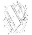
さらに、図13はCD搬送部8のトレイ83の平面図であり、図14は図13のトレイ83の位置検出部の凹部形状を示す模式的断面図であり、図15は図13のトレイとトレイ位置検出センサ59との相対位置の各種の状態を示す模式的平面図であり、図16は記録装置に装着されたCD搬送部8にトレイ83を挿入しセットした状態を示す斜視図であり、図17は記録装置内を通してトレイ83が搬送される状態を示す部分縦断面図であり、図18はキャリッジ50のガイドシャフト52を昇降させるためのシャフト昇降機構のキャリッジ下降時及びキャリッジ上昇時の状態を示す部分縦断面図であり、図19はCD搬送部8の押圧コロ811及び側圧コロ824を示すために該CD搬送部8の一部を破断して示す斜視図である。
【0035】
図6に示すように、CD搬送部8を図示の矢印Y方向に真っ直ぐにスライドさせると、該CD搬送部8は記録装置の下ケース99に装着される。この時、図8及び図9に示す下ケース99の両側に設けたガイドレール993に沿って、トレイガイド82の両端の嵌合部822が挿入されることによって、CD搬送部8の位置決めが行われる。トレイガイド82の左右両側の端部には回動可能なフック84が設けられ、該フック84は一方向に付勢されている。CD搬送部8は、スライドさせて所定位置まで挿入されると、ある部位に突き当たり、それ以上挿入されなくなる。そして、フック84がガイドレール993のストッパーに作用し、CD搬送部8がスライドしてきた方向にも戻らないようにロックがかかる。
トレイガイド82(CD搬送部8)が記録装置の所定位置に装着された状態を機械的に検出するためのトレイガイド検出センサ344がプラテン34に設けられており、トレイガイド82が記録装置本体に装着されると、トレイガイド82の一部がトレイガイド検出センサ344を押すことで、CD搬送部8(トレイガイド82)が装着されたことを検知できるように構成されている。
【0036】
次に、図10及び図12に示すように、スライドカバー81を記録装置の本体方向へ(本体側へ向けて)移動させると、該スライドカバー81と連動してアーム85が記録装置の本体方向へ突出する。拍車42を搭載した拍車ホルダ43はプラテン34に対し上下方向にスライド可能に装着されており、所定圧のばね力で下方向に付勢されている。従って、アーム85が拍車ホルダ43とプラテン34との間に入り込むことで、拍車ホルダ43は上方へ所定量だけ持ち上げられる。この際、アーム85の先端に形成された傾斜部851によって該アーム85はスムーズにプラテン34と拍車ホルダ43との間に入り込むことができる。このことにより、プラテン34と拍車ホルダ43との間に、記憶媒体としてのCD(CD−R等)が搭載されるトレイ83を通過させるためのスペースを形成することができる。
【0037】
また、前記アーム85は、プラテン34と拍車ホルダ43との間に挿入された状態で位置決めされるようになっており、突出する(前進する)前のトレイガイド82内に収納された状態では該トレイガイド82に対しガタを持った状態で収納されている。
また、当初、スライドカバー81を記録装置の本体方向へ移動させない状態では、CD搬送部8の開口部821が閉じられているため、トレイ83を挿入することはできない。そして、スライドカバー81を記録装置の本体方向へ移動させると、スライドカバー81が斜め上方向に移動する構成になっているので、該スライドカバー81とトレイガイド82との間にトレイ挿入用の開口部821が形成される。この状態にすれば、図16に示すように、CDを装填したトレイ83を開口部821から挿入し、所定位置にセットすることができる。
このような構成にする理由は、前記拍車ホルダ43が上昇されていない状態でトレイ83が挿入された場合に、該トレイ83と拍車42とが干渉して該トレイ83の先端のトレイシート831や拍車42が破損することを防止するためである。
【0038】
図11に示すように、トレイガイド82が装着された状態でスライドカバー81を本体から引出すと、該スライドカバー81と連動してアーム85が拍車ホルダ43から外れ、拍車ホルダ43及び拍車44が元の所定位置に下降する。この時、トレイ83が装着されたままであると、スライドカバー81とトレイガイド82との間の開口部821にトレイ83が挟まり、スライドカバー81をそれ以上引出せない構成になっている。これによって、CD−R等の記憶媒体が記録装置本体内に残されたまま拍車44が下がって該CDにダメージを与えるという不具合発生を防いでいる。
さらに、スライドカバー81を引くと、図11に示すように、スライドカバー81がフック84に作用することで、該フック84が下ケース99のガイドレール993から外れることにより、CD搬送部8の記録装置本体への装着が解除される。
【0039】
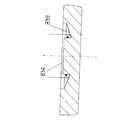
本実施例に係るトレイ83は板厚2〜3mm程度の樹脂板で構成され、該樹脂板には、図13に示すように、CD取り付け部832、トレイの出し入れに操作者が掴む操作部833、位置検出マーク834(図13では、834a、834b、834cの3箇所)、CD取り出し用穴835、挿入位置合わせマーク836、側圧コロ逃げ部387、メディア有無検知マーク838、並びに、トレイアダプタの種類を判別するために設けられたトレイアダプタ種検知用マーク838aが設けられている。
また、上記トレイ83の先端部には、搬送ローラ36及びピンチローラ37へのトレイ83の噛み込みを確実にするためのトレイシート831が取り付けられている。
【0040】
前記位置検出マーク834は、トレイ83のCD取り付け部分の先端側の2箇所(834a、834b)と、その反対側の1箇所(834c)とに設けられている。各位置検出マーク834は3〜10mm程度の正方形に反射性能が高い部材が設けられている。ここでは、ホットスタンプを用いて形成されている。
前記位置検出マーク834の周囲には、図13及び図14に示すように、凹部839が設けられており、樹脂部品の位置検出マーク834部分の形状に沿った形で反射材料を形成できる構成になっている。また、図14に示すように、凹部839の底部は高い表面性を有し所定角度を持って形成されているので、キャリッジ50に設けたトレイ位置検出センサ59の発光が位置検出マーク834以外で反射されても、該反射光が受光部に戻らないように構成されている。これによって、トレイ83の位置検知における誤検知を防ぐことができる。
【0041】
以上のように、トレイ83上の位置検出マーク834の反射率が高いので、高性能のセンサを搭載する必要がなく、補正などの処理を少なくすることができ、コストアップや記録時間(印刷時間)の増大を避けることができる。
また、CDの印刷領域(記録領域)のエッジを直接読み取る方式に比べて、色付きのCDへ印刷したり、一度印刷したCDへ再印刷したりする時でも、CDの位置検出を正確に行うことができる。
前記CD取り付け部832には複数のモールド爪が設けられており、これによって、CDを取り付けた場合の位置決めとがた取りを行っている。操作者は、CDの中央部の穴を前記CD取り付け部832に合わせることにより該CDを取り付ける。CDを取り外す時は、2箇所のCD取り出し用穴835を利用し、操作者がCDの外周エッジを持って取り外すことができる。また、CD取り付け部832は、それ以外のトレイ83の面より一段低くなっている。その低い面にメディア有無検知マーク838が設けられている。このメディア有無検知マーク838は、所定幅のホットスタンプの中に所定幅の穴を設け、この穴幅が検知された場合にメディア無しと判断するように構成されている。
【0042】
図13に示すように、前記トレイ83の先端には、搬送ローラ36及びピンチローラ37への該トレイ83の噛み込みを確実にするために、トレイシート831が取り付けられている。このトレイシート831は、厚み0.1〜0.3mm程度のPET等からなるシート材で形成され、所定の摩擦係数と硬度有している。また、トレイ83自身にも、その先端部にテーパー部830が設けられている。従って、先ず、トレイシート831が搬送ローラ36及びピンチローラ37に噛みこまれることで搬送力が生まれ、次いで、トレイ83の先端のテーパー部830がピンチローラ37を持ち上げることで、厚みがあるトレイ83を搬送ローラ36及びピンチローラ37の間で挟持することにより、トレイ83の正確な搬送が可能になる。
なお、前記位置検出マーク834はピンチローラ37の間に設けられている。従って、前記位置検出マーク834がピンチローラ37と当接することが防止され、これによって、該位置検出マーク834の表面に傷が付くことを防止している。
【0043】
図19において、CD搬送部8を構成するトレイガイド82には、図13に示すようなトレイ83を該トレイガイド82の基準823に押し付けるための側圧コロ824が設けられており、コロばね825によって所定圧でトレイ83を基準823に押し付けることで位置決めを行っている。前記側圧コロ824は、操作者が所定位置にトレイ83をセットするところまでは作用する。しかし、トレイ83が搬送ローラ36及びピンチローラ37により搬送される時には、側圧コロ824が作用する位置に側圧コロ逃げ部387(図13)が来るので、側圧コロ824はトレイ83に作用しなくなる。このように構成する理由は、トレイ83に余計なバックテンションなどが作用することを無くすことにより、該トレイ83の搬送精度の低下を防止するためである。
【0044】
図19に示すように、前記スライドカバー81には左右の押圧コロ811が設けられており、コロばね812によってトレイ83を所定圧で排紙ローラ41に押し付けることで該トレイ83の搬送力を生み出している。この搬送力によって、記録(印刷)開始時にトレイ83をセット位置から搬送ローラ36及びピンチローラ37のニップ部まで搬送することができる。さらに、記録(印刷)終了時には、操作者が取り出す所定位置までトレイ83を搬送することができる。この場合も、前記位置検出マーク834の位置と押圧コロ811の位置とは異なるように構成されており、これによって、前記位置検出マーク834が押圧コロ811と当接してその表面が傷付くことを防いでいる。
そして、所定位置に搬送されたトレイ83を引出すことで、トレイガイド82からトレイ83を取り出すことができる。さらに、2箇所のCD取り出し用穴835を利用することで、操作者はCDの外周エッジを持って該CDを外すことができる。
【0045】
次に、以上説明した構成を有する記録装置によってCDに記録(印刷)する場合の動作について説明する。
先ず、CD搬送部8を記録装置1の本体に向けて真っ直ぐにスライドさせて下ケース99に装着する。この時、トレイガイド検出センサ344(図8)により、トレイガイド82が記録装置本体に装着されたことを検知する。次いで、スライドカバー81を記録装置本体方向へ移動させると、図10に示すように、該スライドカバー81と連動してアーム85が記録装置本体方向へ突出する。そして、アーム85が拍車ホルダ43とプラテン34の間に入り込むことで、拍車ホルダ43を上方へ所定量だけ持ち上げる。
【0046】
このようにスライドカバー81を記録装置本体方向へ移動さると、該スライドカバー81は斜め上方向に移動する構成になっているのでトレイガイド82との間に開口部821(図6)が形成される。この状態で、図16に示すように、CDを装填したトレイ83を開口部821から挿入し、所定位置にセットすることができる。
そして、CDをトレイ83のCD取り付け部832(図13)に装着する。操作者は、操作部833(図13)を持って、挿入位置合わせマーク836(図13、図16)がトレイガイド82のトレイセットマーク826(図16)と一致するところまでトレイ83を挿入する。
【0047】
この状態で、ホストから記録信号(印字信号、画像信号)が送られてくると、記録動作(印字動作)が開始される。まず、図17に示すように、搬送ローラ36、排紙ローラ40及び排紙ローラ41が逆転する。つまり、図17において、押圧コロ811(図19)及びコロばね812によってトレイ83を所定圧で排紙ローラ40及び排紙ローラ41に押し付けることで該トレイ83の搬送力を生み出しているので、排紙ローラ40及び排紙ローラ41の逆転に応じてトレイ83は記録装置内部へ搬送される。
そして、トレイ83の先端部のトレイシート831(図13)が搬送ローラ36及びピンチローラ37に噛み込まれることで所定の搬送力が生まれ、トレイ83の先端部のテーパ部830がピンチローラ37を持ち上げることにより、トレイ83が搬送ローラ36及びピンチローラ37に挟持される。
【0048】
次に、記録ヘッド7を搭載したキャリッジ50が、トレイ83を検出するためにホームポジションから記録領域(印字領域)に移動する。この時に、図18に示すように、キャリッジ昇降モータ58(図3)が作動してガイドシャフト52を上昇させ、記録ヘッド7とトレイ83との間に最適なギャップ(紙間距離)を形成することができる。
図15の(a)及び(b)に示すように、キャリッジ50は該キャリッジ上のトレイ位置検出センサ59を前記トレイ83の位置検出マーク834a(図13)のキャリッジ移動方向位置に合わせて停止する。そして、トレイ83を搬送し、位置検出マーク834aの上端(先端)のエッジ位置を検出する。そのまま、搬送を続け、マーク834aの下端エッジ(後端エッジ)を検出する。
【0049】
次に、図15の(c)に示すように、キャリッジ50上のトレイ位置検出センサ59がトレイ83の位置検出マーク834aの略中央に来るようにトレイ83を戻す。そして、キャリッジ50を左右に移動させ、位置検出マーク834a右端のエッジ位置及び左端のエッジ位置を検出する。以上より、位置検出マーク834aの中心位置834ac(図13)を算出することができ、該中心位置834acより、トレイ83に搭載されたCDの正確な記録位置(印刷位置)を求めることができる。以上のように、本実施例においては、トレイ83自身の位置検出を行うので、検出を行わずに機械的(メカ的)な精度のみで印刷を行う場合に比べて、部品精度のバラツキやトレイの状態などの影響を受けてCDに対する記録位置(印刷)がずれることを無くすことができる。
【0050】
トレイ83の位置検出マーク834aの位置(その中心位置834ac)を検出した後に、キャリッジ50は図15の(d)に示すように、位置検出マーク834bを検出するために移動する。この位置検出マーク834bの両端のエッジを検出することで、先程検出した位置検出マーク834aが間違いないことを確認する。このような操作を行う理由は、トレイ83が正規のセット位置よりも奥に挿入された場合に、図15の(e)に示すように、位置検出マーク834cの位置を検出しても、位置検出マーク834bを検出するために移動する動作によって、位置検出マーク834aでは無いことを検知することができるようにするためである。
【0051】
トレイ83の位置が検出された後に、図15の(f)に示すように、トレイ83の搬送方向に、キャリッジ50のトレイ位置検出センサ59の位置とトレイ83のメディア有無検出マーク838(図13)の位置が一致するようにトレイ83を搬送する。
この時に、メディア有無検出マーク838の検出穴のエッジを検出し、所定穴幅と一致すると、CDが搭載されていないと判断し、記録動作(印刷作業)を中断し、トレイ83を所定位置まで排出し、エラーを表示する。ここで、上記メディア有無検出マーク838が検出できなければ、CDが搭載されていると判断し、記録動作を継続する。
【0052】
以上の一連の初期動作が終了したところで、トレイ83を記録装置(プリンタ等)の奥のCD全体を記録(印字)できる所定位置まで搬送する。その後、ホストからの送られる記録データ(画像データ)に応じて記録(印字、印刷)を開始する。記録される画像に関しては、複数走査で画像を形成するいわゆるマルチパス印字を用いることにより、CDの搬送精度及びヘッド7の着弾精度による記録画像のバンドムラ等を軽減することができる。
記録(印刷)が終了した後に、トレイ83を、前述の印刷前に操作者がトレイガイド82にトレイ83をセットした位置まで搬送する。この状態で、操作者は印刷が行われたCDが搭載されたトレイ83を取り出すことができる。さらに、スライドカバー81を手前に引く(記録装置本体から離れる方向へ移動させる)ことで、アーム85が拍車ホルダ43から解除され、フック84が下ケース99から解除されることで、CD搬送部8が記録装置本体から解除され、取り外すことができる。
以上説明した記録装置(画像形成装置)の構成及び動作(作用)により、CD等の被記録材に記録を行うことができる。
【0053】
ここで、本実施例ではキャリッジ上に搭載されたトレイ位置検出センサ59でトレイの位置を検出して記録を行っているが、実際に記録を行うのは記録ヘッド7であるため、前記トレイ位置検出センサ59と記録ヘッド7の位置が正しくないと記録位置がずれてしまう。
そこで、図20から図25を用いて、本発明を適用した記録装置の一実施例における前記トレイ位置検出センサ59と記録ヘッド7との位置を調整するための手段について説明する。
図20は本発明を適用した記録装置の第1実施例におけるキャリッジ50上のトレイ位置検出センサ59と記録手段(記録ヘッド)7との位置関係を示す模式的平面図である。図20において、キャリッジ50に記録ヘッド7が搭載されており、該記録ヘッド7は、不図示のばね等により図20中に示す矢印R方向に付勢されることで、前記キャリッジの位置決め部502に当接している。
【0054】
前記記録ヘッド7にはインクを吐出して記録を行うための吐出口(複数の吐出口から成る吐出口列)701が形成されており、吐出口701の基準となる第1吐出口が701aで示されている。この第1吐出口701aは前記キャリッジ50の位置決め部502に当接する部分を基準として寸法管理されており、X方向は寸法J1で、Y方向は寸法K1で表されている。
また、キャリッジ50には前記トレイ位置検出センサ59が取り付けられており、該センサ59の位置は、前記記録ヘッド7との位置決め部502を基準として寸法管理されており、X方向は寸法J3で、Y方向は寸法K3でそれぞれ表されている。
【0055】
図20において、実際にCD等の被記録材へ記録を行う際には、前記トレイ位置検出センサ59でトレイ83の位置を検出し、それを基準にして記録ヘッド7で記録を行うので、該トレイ位置検出センサ59と記録ヘッド7との距離が必要となり、X方向は寸法J2で表され、Y方向は寸法K2で表されている。
ここで、記録ヘッド7の位置を表す前記寸法J1及びK1は、記録ヘッド製造時に例えば基準面を追加工するなどの措置を採ることにより、精度を上げることが容易であるが、記録手段を移動させるための記録手段移動手段としてのキャリッジ50に搭載するトレイ位置検出センサ59の位置に関しては、精度を上げると必然的にかなりのコストアップを招くことになる。そこで、本実施例では、キャリッジ50に搭載されたトレイ位置検出センサ59の所定位置からのずれ量を測定し、この測定結果(位置ずれの量)を記録装置の制御手段内に記憶させ、記録時にこの位置ずれの量を補正して記録を行うように構成されている。
【0056】
図21は、本発明を適用した記録装置の第1実施例において、記録手段移動手段である前記キャリッジ50に、前記トレイ位置検出センサ59の位置を補正するための調整用ヘッド10を搭載した状態を示す模式的平面図である。図21において、調整用ヘッド10には調整用センサ101が取り付けられており、記録ヘッド7と同様に前記キャリッジ50の突き当て部502に押圧されている。前記調整用ヘッド10と前記調整用センサ101は本発明における調整手段を構成するものである。前記調整用センサ101は、後述する校正手段(校正方法)により、前記記録手段移動手段としてのキャリッジ50の位置決め部(突き当て部)502からの位置、すなわち図21中の寸法L1及び寸法M1が正確になっている。この状態で、前記トレイ位置検出センサ59及び調整用センサ101によって、前述のトレイ83(図13)に配設された位置検出マーク834あるいは同等の検出マークを移動させてY方向を読み取り、かつ、前記キャリッジ50を該位置検出マーク834に対して移動させることによってX方向を読み取る。前記トレイ位置検出センサ59と調整用センサ101が正しい位置にあると、所定値としてのX方向寸法はL2となり、Y方向寸法は0(零)となるが、検出された値がLa(X方向)及びMa(Y方向)である場合には、前記所定値に対してX方向にはLa−L2、Y方向にはMa−0の分ずれていることになる。
【0057】
図22は、本発明を適用した記録装置の第1実施例において、記録手段移動手段としての前記キャリッジ50に記録手段(記録ヘッド)7又は前記調整用ヘッド10を搭載したときの状態を示す斜視図であり、図22の(a)は記録ヘッド7を搭載したときの状態を示しており、図22の(b)は調整用ヘッド10を搭載したときの状態を示している。図22の(a)に示すように、記録ヘッド7にはインクタンク71がセットされている。また、図22の(b)に示すように、前記調整用ヘッド10は、記録ヘッド7の代わりに該記録ヘッドと同様に搭載されている。すなわち、前記調整用ヘッド10は、前記記録ヘッド7と類似の形状をしており、記録手段移動手段としてのキャリッジ50に対して該記録ヘッドと同様に装着可能となっている。また、前述のように、記録ヘッド7はキャリッジ基板92及びコンタクト921を介して電気的接続をされており、前記調整用ヘッド10も同様にキャリッジ基板92と電気的接続が可能となっている。
【0058】
図23は図21及び図22における第1実施例に係る調整用ヘッド10の校正方法を説明するための模式図である。
前述の通り、前記トレイ位置検出センサ59の取付け位置は前記調整用ヘッド10の調整用センサ101を基準に測定されるため、該調整用ヘッド10の調整用センサ101の位置が正確でなければ正確で正しい測定は不可能になる。また、調整用ヘッド10及び調整用センサ101を高精度に製造してもある程度の誤差は生じる。そこで、本実施例では、調整用センサ101の所定位置からのずれ量を測定し、そのずれ量の分の補正を行う校正方法が採られる。
【0059】
図23の(a)において、調整用ヘッド10は、調整用ヘッド校正台102に搭載されており、不図示のばね等により調整用ヘッド位置決め部102aに当接している。103は校正用検出マークであり、この校正用検出マーク103は図中のX方向及びY方向に移動可能な不図示の台に取り付けられている。この不図示の台は、X−Yステージのようなダイヤルゲージの取り付けられたものや、リニアーモータ等により駆動し、その位置をレーザー等の測定器で測定して位置を計測できるような台であればよく、このような台を使用することにより、前記調整用ヘッド位置決め部102aからの距離LL(X方向)及びMM(Y方向)を正確に測定することができる。前記調整用ヘッド校正台102、前記調整用ヘッド位置決め部102a及び前記校正用検出マーク103は本発明における校正手段を構成するものである。
【0060】
図23の(b)は、図23の(a)の状態から、前記校正用検出マーク103をR方向へ移動させて前記調整用センサ101に対向させたときの状態を示している。ここで、前記調整用センサ101は、発光素子と受光素子とを有し、発光素子から発光された光が対向部から反射した反射光を受光素子で受光する所謂反射型センサであり、前記校正用検出マーク103は光を反射しやすいよう鏡面でできている。従って、校正用検出マーク103が調整用センサ101に対向する位置を通過することで、反射光有り及び反射光無しを検出することができる。図23の(b)は反射光有りから反射光無しに変化する状態を示しており、この位置が校正用検出マーク103の位置である。この時の距離LL(X方向)の測定値と調整用センサ101が本来あるべき位置の距離L(X方向)との差が、所定値とのずれである。
【0061】
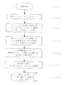
図24は図21及び図22における第1実施例に係る調整用ヘッド10の校正方法を実施する際の動作手順を例示するフローチャートであり、図25は図24の第1実施例に係る校正方法で校正された調整用ヘッド10を用いてキャリッジ50上のトレイ位置検出センサ59の調整を行うための動作手順を例示するフローチャートである。
次に、図24及び図25を用いて、本発明を適用した記録装置の第1実施例における調整手段及び校正手段の動作、すなわち調整用ヘッド10の校正からトレイ検出センサ59の補正までの手順について説明する。
図24において、校正を開始する(ステップS01)と、先ず、調整用ヘッド10を調整用ヘッド校正台102にセットし(ステップS02)、校正用検出マーク103を図23中のR方向へ移動させ、調整用センサ101によって該検出マーク103の所定位置を検出する(ステップS03)。
【0062】
次に、前記校正用検出マーク103を図23中の矢印V方向へ移動させ、同様に調整用センサ101で該検出マークの所定位置を検出する(ステップS04)。そして、ステップS03及びステップS04で検出された校正用検出マーク103の位置(X、Y)と調整用センサ101の本来あるべき位置との差を算出する(ステップS05)。ステップ05で求めた位置ずれ量(ΔXa、ΔYa)を前記調整用ヘッド10に固有の値として、記憶装置に記憶させるか、あるいは、後述する記録ヘッドの調整時まで控えておく(ステップS06)。
【0063】
次に、図25のフローチャートを用いて、校正された調整用ヘッド10を用いてキャリッジ50上のトレイ位置検出センサ59の調整を行う動作手順を説明する。
図25において、調整を開始する(ステップS11)と、調整用ヘッド10をキャリッジ50にセットし(ステップS12)、キャリッジをX方向(図23)へ移動させ、同一の検出マークを前記トレイ位置検出センサ59と調整用センサ101で読み取る(ステップS13)。次に、キャリッジ50が停止した後、検出マークを図23中のY方向へ移動させ、同様にトレイ位置検出センサ59と調整用センサ101で検出マークを読み取る(ステップS14)。
【0064】
続いて、前記ステップS13及びステップS14で検出した位置と、本来のトレイ位置検出センサ59と調整用センサ101の相対位置からのずれ量を算出する(ステップS15)。このずれ量に前述の調整用ヘッド校正値(ΔXa、ΔYa)を加算し(ステップS16)、得られた値をトレイ位置検出センサ59の補正値(ΔX、ΔY)として記録装置の記憶手段に記憶させる(ステップS17)。
このように補正値を記録装置の記憶手段に記憶させることにより、前述のようにトレイ83に配設されたトレイ位置検出マーク834を検出し、それを基準に、記録を行う際に、この補正値を加算した位置に記録を行えば、正確な位置に記録を行うことが可能となる。
以上のような図13及び図20〜図25を参照して説明した実施例(第1実施例)の構成及び動作により、簡単な操作で、CD上に精度良く印刷を行うことができる。
【0065】
図26は本発明に関連した第1の参考例に係る記録装置におけるトレイ位置検出センサ59を調整するときの機構部を示す斜視図である。
前述の第1実施例における調整手段においては、トレイ位置検出センサ59の取り付け位置を調整用ヘッド10の調整用センサ101を使って測定し補正したが、本参考例では、記録装置内に調整用検出マークを取付け、これをトレイ位置検出センサ59で検出することにより該センサの位置を調整するように構成されている。
【0066】
すなわち、図26においては、記録ヘッド7に対向した位置に配置されたプラテン34上に、校正用検出マーク105aが形成された校正用検出プレート105が一時的に取り付けられおり、図26中のX方向及びY方向に関して記録装置内の正しい位置に取り付けられるようになっている。X方向については、前述の通り記録手段移動手段としてのキャリッジ50はコードストリップ561(図3、図4)をエンコーダーセンサ56で読み取って走査しているが、その基準はシャーシ11の右側板11a(図26)に該キャリッジ50を当接することによって定められている。従って前記校正用検出プレート105も前記右側板11aを基準に取り付けられており、校正用検出マーク105aの位置が右側板11aからX方向に正しい距離の位置に存在するようになっている。また、Y方向についてはキャリッジ50のX方向への走査を案内するガイドシャフト52を基準にすることで、正しい位置に取り付くようにし、かつ搬送ローラ36及びピンチローラ37に挟持されることにより、Y方向に搬送できるようになっている。
【0067】
この状態で、前記キャリッジ50をシャーシ11の右側板11aに当接させて位置出しを行い、そこから該キャリッジ50を図中X方向へ走査させ、前記トレイ位置検出センサ59で前記校正用検出プレート105の校正用検出マーク105aの端部を検出する。検出した校正用検出マーク105aの端部位置が所定量と異なっている場合は、それをX方向の補正値とする。
Y方向については、本来校正用検出マーク105aは正しい位置に取り付けられているので、前述のキャリッジをX方向に走査させてトレイ位置検出センサ59で読み取りを行うと、検出できるかできないかのどちらかであり、校正用検出マーク105aの端部位置が正しいかどうかは分からない。
【0068】
そこで、校正用検出マーク105aがあると検出された場合は、校正用検出プレート105を排紙部4の方向へ搬送しながら校正用検出プレート105の端部を検出する。また、上記で校正用検出マーク105aが無しと検出された場合は、校正用検出プレート105を給紙部2の方向へ搬送し、同様に校正用検出マーク105aの端部を検出する。このように得られた値が所定値と異なる場合はY方向の補正値とする。
以上のようにX方向及びY方向の補正値が算出されると、記録装置内の記憶装置に記憶され、前述の実施例と同様にトレイ位置検出センサ59で検出されたトレイ位置検出マーク834(図13)を基準にトレイ83に記録する際に、この補正値を加算した位置に記録を行うことにより、正しい位置への記録が可能となる。
【0069】
図27は本発明に関連した第2の参考例に係る記録装置におけるキャリッジ50上の記録ヘッド7とトレイ位置検出センサ59とを示す模式的平面図である。
前述の第1実施例及び第1の参考例では、キャリッジ50上に搭載されたトレイ位置検出センサ59の取り付け位置を検出して補正していたが、本参考例では、記録ヘッド7で記録を行った画像をキャリッジ上のトレイ位置検出センサ59で読み取って補正するように構成されている。
図27の(a)及び(b)には、キャリッジ50に記録ヘッド7とトレイ位置検出センサ59が同時に搭載されており、記録ヘッド7で記録を行った画像をトレイ位置検出センサ59で読み取る場合の状態が示されている。
【0070】
図27の(a)は、X方向の位置調整を行う場合が示されており、記録ヘッド7の吐出口701を用いて縦1本の線Q1を記録した後、記録シートPをYb方向に1改行分搬送し、同様に2本目の縦線Q2を記録した状態であり、ここでキャリッジ50をX方向へ走査させることによりトレイ位置検出センサ59で縦線Q1を検出することができる。
前述の通りキャリッジ50の位置については、コードストリップ561を該キャリッジに搭載されたエンコーダーセンサ56で読み取ることにより、基準からの位置を検出することができる。そのため、記録ヘッド7で縦線を記録したキャリッジ50の位置と、トレイ位置検出センサ59で同じ縦線を検出したときのキャリッジ50の位置とを比較することにより、その差を算出し、算出された値が所定値と異なる場合は、その分がずれ量となる。そこで、このずれ量の分の補正をすれば良いことになる。
【0071】
また、図27(b)は、Y方向の位置調整を行う場合が示されており、記録ヘッド7の吐出口701の何れかを用いて横1本の線Q3を記録した後、キャリッジ50をX方向で該横線Q3上にトレイ位置検出センサ59が対向する位置に移動させてそこに停止させ、その後記録シートPをYb方向に搬送させながら、トレイ位置検出センサ59で横線Q3を検出する。
ここでトレイ位置検出センサ59が横線Q3を検出するまでに、記録シートPがYb方向へ搬送された搬送量を検出し、その搬送量が吐出口701とトレイ位置検出センサ59のオフセット量KKが異なる場合は、その分がずれ量となるためこれを補正値とする。
このように記録された画像をトレイ位置検出センサ59で読取り、所定量とのずれを算出することにより、吐出口とトレイ位置検出センサ59のズレ量を認識することができ、前述の実施例と同様にトレイ位置検出センサ59で検出されたトレイ位置検出マーク834(図13)を基準にトレイに記録する際に、この補正値を加算した位置に記録を行うことにより、正しい位置への記録が可能となる。
【0072】
なお、前述の実施例では、記録装置がインクジェット記録装置である場合を例に挙げて説明したが、本発明は、ワイヤドット式、感熱式、レーザービーム式の記録装置など、他の記録方式を用いる記録装置に対しても同様に適用することができ、同様の作用効果を達成できるものである。
【0074】
また、本発明は、液体インクを用いて記録するインクジェット記録装置の場合、記録ヘッドとインクタンクを一体化した交換可能なヘッドカートリッジを用いる構成、記録ヘッドとインクタンクを別体にし、その間をインク供給用のチューブ等で接続する構成など、記録ヘッドとインクタンクの配置構成がどのような場合にも同様に適用することができ、同様の効果が得られるものである。
さらに、本発明は、インクジェット記録装置の場合、例えば、ピエゾ素子等の電気機械変換体等を用いる記録手段を使用するものにも適用できるが、中でも、熱エネルギーを利用してインクを吐出する方式の記録手段を使用するインクジェット記録装置において優れた効果をもたらすものである。かかる方式によれば、記録の高密度化、高精細化が達成できるからである。
【0075】
【発明の効果】
以上の説明から明らかなごとく、本発明によれば、被記録材に記録を行う記録ヘッドまたは調整用センサを備える調整用ヘッドを搭載して移動するためのキャリッジと、前記キャリッジに配され、被記録材の位置を検出するための検出センサと、を備え、前記キャリッジに前記調整用ヘッドを搭載して前記調整用センサと前記検出センサで同一のマークを読み取り、前記調整用センサと前記検出センサとの相対位置のずれ量から記録ヘッドを搭載して記録を行うときの補正値を算出するように構成したので、簡単な構成で、キャリッジに配された検出センサと記録ヘッドとのずれ量を算出することができ、被記録材の正確な位置に記録することができる記録装置が提供される。
【図面の簡単な説明】
【図1】 本発明を適用した記録装置の一実施例を示す斜視図である。
【図2】 図1の記録装置で給紙トレイ及び排紙トレイを開いた状態を示す斜視図である。
【図3】 本発明を適用した記録装置の一実施例の内部機構を右前方から見て示す斜視図である。
【図4】 図3の記録装置の内部機構を左前方から見て示す斜視図である。
【図5】 図3の記録装置の縦断面図である。
【図6】 図1の記録装置にCD搬送部を装着する前後の状態を示す斜視図である。
【図7】 図1の記録装置に装着可能なCD搬送部を示す斜視図である。
【図8】 本発明を適用した記録装置の一実施例における下ケースのCD搬送部取付け部及び取付け検出部を示す部分斜視図である。
【図9】 本発明を適用した記録装置の一実施例における下ケースとCD搬送部のフックの装着状態を示す部分縦断面図である。
【図10】 本発明を適用した記録装置に装着可能なCD搬送部の装着前後においてスライドカバーを移動させたときの状態を示す斜視図である。
【図11】 本発明を適用した記録装置の一実施例における下ケースからCD搬送部のフックを解除したときの状態を示す部分縦断面図である。
【図12】 本発明を適用した記録装置の一実施例におけるCD搬送部のスライドカバー移動前後におけるアームの状態を示す部分縦断面図である。
【図13】 本発明を適用した記録装置の一実施例におけるCD搬送部のトレイの平面図である。
【図14】 図13のトレイの位置検出部の凹部形状を示す模式的断面図である。
【図15】 図13のトレイとトレイ位置検出センサとの相対位置の各種の状態を示す模式的平面図である。
【図16】 本発明を適用した記録装置の一実施例に装着されたCD搬送部にトレイを挿入しセットした状態を示す斜視図である。
【図17】 本発明を適用した記録装置の一実施例内を通してトレイが搬送される状態を示す部分縦断面図である。
【図18】 本発明を適用した記録装置の一実施例におけるキャリッジのガイドシャフトを昇降させるためのシャフト昇降機構のキャリッジ下降時及びキャリッジ上昇時の状態を示す部分縦断面図である。
【図19】 本発明を適用した記録装置の一実施例に装着されるCD搬送部の押圧コロ及び側圧コロを示すために該CD搬送部の一部を破断して示す斜視図である。
【図20】 本発明を適用した記録装置の第1実施例における記録手段移動手段上のトレイ位置検出センサと記録手段との位置関係を示す模式的平面図である。
【図21】 本発明を適用した記録装置の第1実施例において記録手段移動手段にトレイ位置検出センサの位置を補正するための調整用ヘッドを搭載した状態を示す模式的平面図である。
【図22】 本発明を適用した記録装置の第1実施例において記録手段移動手段に記録手段を搭載したときの状態(a)及び調整用ヘッドを搭載したときの状態(b)を示す斜視図である。
【図23】 図21及び図22における調整用ヘッドの校正方法を説明するための模式図である。
【図24】 図21及び図22における第1実施例に係る調整用ヘッドの校正方法を実施する際の動作手順を例示するフローチャートである。
【図25】 図24の第1実施例に係る校正方法で校正された調整用ヘッドを用いて記録手段移動手段上のトレイ位置検出センサの調整を行うための動作手順を例示するフローチャートである。
【図26】 本発明に関連した第1の参考例に係る記録装置におけるトレイ位置検出センサを調整するときの機構部を示す斜視図である。
【図27】 本発明に関連した第2の参考例に係る記録装置における記録手段移動手段上の記録手段とトレイ位置検出センサとを示す模式的平面図である。
【符号の説明】
1 記録装置
2 給紙部
3 送紙部
4 排紙部
5 キャリッジ部(記録手段移動手段)
6 回復機構部(クリーニング部)
7 記録手段(記録ヘッド)
8 CD搬送部
9 電気部
10 調整用ヘッド
101 調整用センサ
102 調整用ヘッド校正台
103 校正用検出マーク
105 校正用検出プレート
11 シャーシ
111 ガイドレール
20 ベース
201 前段分離部
21 圧板
211 ローレット部
212 圧板ばね
213 分離シート
214 圧板カム
22 戻しレバー
221 戻しレバーばね
23 可動サイドガイド
231 シートガイド部
232 ローレット対応部
233 操作部
24 分離ローラホルダ
241 分離ローラ
242 分離ローラばね
243 分離ローラクラッチ
244 分離ローラリリースシャフト
245 分離ローラ軸
25 コントロールカム
26 給紙トレイ
27 駆動部
271 駆動伝達ギア
272 遊星ギア
273 給紙モータ
28 給紙ローラ
281 給紙ローラゴム
29 ASFセンサ
30 ピンチローラホルダ
31 ピンチローラばね
32 PEセンサ
321 PEセンサレバー
33 ペーパーガイドフラッパー
331 軸受部
34 プラテン
341 紙押さえ
342 搬送ローラ取り付け部
343 シャーシ取り付け軸
344 トレイガイド検出センサ
35 搬送モータ
36 搬送ローラ
361 プーリ
362 コードホイール
37 ピンチローラ
38 軸受
381 ローラテンションばね
39 エンコーダーセンサ
40 排紙ローラ
41 排紙ローラ
42 拍車
43 拍車ホルダ
44 拍車ばね
45 紙端サポート
451 紙端サポートコロ
452 紙端サポートばね
46 排紙トレイ
50 キャリッジ
501 突き当て部
502 突き当て部
51 ヘッドセットレバー
511 ヘッド押圧手段
52 ガイドシャフト
521 偏心カム
53 摺動シート
54 キャリッジモータ
541 タイミングベルト
542 アイドルプーリ
55 キャリッジダンパー
56 エンコーダーセンサ
561 コードストリップ
57 フレキシブル基板
58 キャリッジ昇降モータ
581 駆動ギア列
59 トレイ位置検出センサ
60 ポンプ
61 キャップ
611 キャップ吸収体
62 ブレード
63 メインカム
64 位置検出センサ
65 連結チューブ
66 ブレードクリーナー
67 ポンプチューブ
68 ポンプコロ
69 回復モータ(クリーニングモータ)
7 記録手段(記録ヘッド)
701 吐出口(列)
701a 第1の吐出口
71 インクタンク
8 CD搬送部
81 スライドカバー
811 押圧コロ
812 コロばね
82 トレイガイド
821 開口部
822 嵌合部
823 基準
824 側圧コロ
825 コロばね
826 トレイセットマーク
83 トレイ(CD印刷用)
830 テーパー部
831 トレイシート
832 CD取り付け部
833 操作部
834 位置検出マーク
835 CD取り出し用穴
836 トレイ挿入位置合わせ用マーク
837 側圧コロ逃げ部
838 メディア有無検知用マーク
839 位置検出マークの凹部
84 フック
85 アーム
851 傾斜部
91 メイン基板
92 キャリッジ基板
921 コンタクト
95 フロントカバー
96 コネクタカバー
97 アクセスカバー
98 上ケース
981 ドアスイッチレバー
982 LEDガイド
983 キースイッチ
99 下ケース
991 廃インク吸収体
992 排紙トレイレール
993 CD搬送部のガイドレール[0001]
[Industrial application fields]
The present invention relates to a recording apparatus that performs recording on a recording material by a recording head mounted on a carriage.
[0002]
[Prior art]
Conventionally, various recording materials have been proposed for recording by a recording apparatus such as a printer or an image forming apparatus. Among them, there are small and thick recording materials such as CD-Rs, DVDs, and cards (hereinafter collectively referred to as CDs (compact discs)). In the current general-purpose recording device, when recording on a recording material such as a CD, if a single sheet paper transport path is used, the transportability is deteriorated or scratches are caused due to the high rigidity of the CD. Or problems such as inability to convey due to the distance between the conveying rollers. Therefore, when transporting a small and thick recording material such as a CD, a tray for mounting an image recording material is used and transported through a path different from the transport path of the cut sheet. ing.
[0003]
When the tray is used, since the thickness of the tray is larger than that of general sheet paper, the tray is inserted into the conveyance roller pair, sandwiched by the conveyance roller pair, and between the recording means (recording head) and the recording material. It is necessary to give sufficient consideration to securing appropriate gaps. As one means for that purpose, there is a method in which an operating lever is provided in the recording apparatus, and the pressing of a conveying member such as a conveying roller is released in conjunction with the movement of the operating lever. In this case, when the user inserts the tray to a predetermined position and adjusts the position, the user operates the operation lever to set the transport member in the pressed state again.
Further, the carriage on which the recording head is mounted is raised by the operation lever, and a gap (distance between the recording materials) is ensured.
[0004]
Further, when recording (printing) on a recording material such as a CD, a method of performing recording without detecting the position of the recording material such as a CD or a sensor mounted on a carriage is used. A method of recording by directly detecting the position of the white part in the recording range is employed. However, if the position of the recording material is not detected, the recorded image is shifted with respect to the recording material such as a CD. Therefore, it is necessary for the user to adjust the recording apparatus with an application on a personal computer or the like. It is. Therefore, recently, a method of recording by detecting the position of the recording material by a sensor (tray position detection sensor or the like) mounted on the carriage is frequently used.
[0005]
[Problems to be solved by the invention]
However, in such a method of detecting the position of a recording material such as a CD using a sensor mounted on the carriage, it is impossible to record at a correct position unless the position of the sensor and the recording head as recording means is accurate. Therefore, it is necessary to improve the sensor mounting accuracy, and therefore, it is necessary to improve the accuracy of the shape and size of the parts and to employ a precise assembly method, which increases the cost.
The present invention has been made in view of such a technical problem, and an object of the present invention is to calculate a deviation amount between a detection sensor arranged on a carriage and a recording head with a simple configuration, It is an object of the present invention to provide a recording apparatus capable of recording at an accurate position of a recording material.
[0006]
[Means for Solving the Problems]
In order to achieve the above object, a first aspect of the present invention provides a carriage for moving an adjustment head having a recording head or an adjustment sensor for recording on a recording material, and a carriage disposed on the carriage. A detection sensor for detecting the position of the recording material, the adjustment head is mounted on the carriage, the same mark is read by the adjustment sensor and the detection sensor, and the adjustment sensor and the detection sensor A correction value for performing recording with the recording head mounted is calculated from the amount of relative positional deviation.
[0010]
DETAILED DESCRIPTION OF THE INVENTION
Embodiments of the present invention will be specifically described below with reference to the drawings. Note that the same reference numerals denote the same or corresponding parts throughout the drawings.
1 is a perspective view showing an embodiment of a recording apparatus to which the present invention is applied, and FIG. 2 is a perspective view showing a state in which a paper feed tray and a paper discharge tray are opened in the recording apparatus of FIG. FIG. 4 is a perspective view showing the internal mechanism of the recording apparatus of FIG. 1 as viewed from the right front, FIG. 4 is a perspective view of the internal mechanism of the recording apparatus of FIG. 3 as viewed from the left front, and FIG. 6 is a longitudinal sectional view of the recording apparatus, FIG. 6 is a perspective view showing a state before and after mounting the
8 to 19 are diagrams for explaining the configuration and operation for CD printing in an embodiment of the recording apparatus to which the present invention is applied.
1 to 5, a
[0011]
(A) Paper feed unit
The
[0012]
The paper feed roller 28 has a bar shape with a circular arc in cross section, and the paper feed roller 28 is provided with one separation roller rubber (paper feed roller rubber) 281 based on the paper standard. Sheet feeding (sending out) of the sheet material is performed by such a sheet feeding roller 28. The paper feed roller 28 is driven by a driving force transmitted from a
[0013]
Further, a
The
[0014]
A state of feeding paper using the above configuration will be described below.
In a normal standby state, the
When paper feeding starts from this state, first, the separation roller 241 contacts the paper feeding roller 28 by driving the motor. Then, the
[0015]
When the sheet material P reaches a conveyance roller pair composed of a
[0016]
(B) Paper feed section
A
[0017]
The
[0018]
Further, a paper presser 341 that covers an end portion of the sheet material P is provided on the paper reference side of the
In the above-described configuration, the sheet material P sent to the
[0019]
The
A code wheel 362 for detecting the amount of conveyance by the
An ink jet recording head is used as the recording means (recording head) 7. A separate ink tank is replaceably mounted on the
[0020]
(C) Carriage part
The
[0021]
The carriage unit 5 (carriage 50) is driven via a timing belt 541 by a carriage motor 54 attached to the chassis 11. The timing belt 541 is stretched and supported by an idle pulley 542. The timing belt 541 and the
[0022]
In order to fix the
Further, an eccentric cam R (right-side eccentric cam) 521 and an eccentric cam L (left-side eccentric cam) 522 are provided at both ends of the
[0023]
Further, the
In the above configuration, when an image is formed on the sheet material P, the pair of rollers (conveying rollers and pinch rollers) 36 and 37 conveys the sheet material P to a recording row position (position in the conveying direction of the sheet material P). At the same time, the
[0024]
(D) Paper discharge unit
The
The
[0025]
As the
[0026]
A paper end support 45 is provided between the
[0027]
With the above configuration, the sheet material P recorded (image formation) by the
[0028]
(E) Recovery mechanism section (cleaning section)
The recovery mechanism section (cleaning section) 6 includes a pump (a suction pump or the like as a negative pressure generation source) 60 for performing a suction recovery process (cleaning operation) for maintaining and recovering the ejection performance of the
The
[0029]
In this embodiment, the pump 60 is configured to generate a negative pressure by squeezing two tubes 67 with a pump roller 68, and a valve 65 is provided in the middle of a suction path (tube or the like) from the cap 61 to the pump 60. Etc. are provided. This suction recovery means generates a negative pressure in the cap 61 by applying the pump 60 in a state where the cap 61 is in close contact with the ejection port surface of the recording head 7 (capping state), and recording is performed by the negative pressure. It is configured to suck and discharge thickened ink, foreign matters such as bubbles and dust together with ink from the ejection port of the
A cap absorber 611 for reducing the amount of residual ink (attached ink) on the ejection port surface of the
[0030]
Various recovery processing operations in the
The position (rotation position, etc.) of the main cam 63 can be detected by a position detection sensor 64 such as a photo interrupter. Further, when the cap 61 is separated from the recording head (in the present embodiment, when it is lowered), the blade 62 moves in a direction orthogonal to the main scanning direction of the
[0031]
(F) Exterior part
Each functional part and each mechanism part (each unit) described above is incorporated in the chassis 11 of the
A discharge tray rail 992 is provided below the
[0032]
An access cover 97 is rotatably attached to the
Further, the
Further, a multistage
[0033]
Next, in the recording apparatus to which the present invention is applied, the configuration in the case of using a CD (compact disc)
6 is a perspective view showing a state before and after mounting the
[0034]
13 is a plan view of the
[0035]
As shown in FIG. 6, when the
A tray
[0036]
Next, as shown in FIGS. 10 and 12, when the
[0037]
The
In addition, when the
The reason for this configuration is that when the
[0038]
As shown in FIG. 11, when the
Further, when the
[0039]
The
A
[0040]
The
As shown in FIGS. 13 and 14, a
[0041]
As described above, since the reflectance of the
Compared to the method of directly reading the edge of the print area (recording area) of the CD, the CD position can be accurately detected even when printing on a colored CD or reprinting on a printed CD. Can do.
The
[0042]
As shown in FIG. 13, a
The
[0043]
In FIG. 19, the
[0044]
As shown in FIG. 19, the
The
[0045]
Next, an operation when recording (printing) on a CD by the recording apparatus having the above-described configuration will be described.
First, the
[0046]
Thus, when the
Then, the CD is mounted on the CD mounting portion 832 (FIG. 13) of the
[0047]
In this state, when a recording signal (printing signal, image signal) is sent from the host, a recording operation (printing operation) is started. First, as shown in FIG. 17, the
Then, the tray sheet 831 (FIG. 13) at the front end of the
[0048]
Next, the
As shown in FIGS. 15A and 15B, the
[0049]
Next, as shown in FIG. 15C, the
[0050]
After detecting the position of the
[0051]
After the position of the
At this time, the edge of the detection hole of the medium presence /
[0052]
When the above series of initial operations is completed, the
After the recording (printing) is completed, the
Recording can be performed on a recording material such as a CD by the configuration and operation (action) of the recording apparatus (image forming apparatus) described above.
[0053]
In this embodiment, the tray
Accordingly, means for adjusting the positions of the tray
FIG. 20 is a schematic plan view showing the positional relationship between the tray
[0054]
The
The
[0055]
In FIG. 20, when recording is actually performed on a recording material such as a CD, the position of the
Here, the dimensions J1 and K1 representing the position of the
[0056]
FIG. 21 shows a state in which the
[0057]
FIG. 22 is a perspective view showing a state when the recording means (recording head) 7 or the
[0058]
FIG. 23 is a schematic diagram for explaining a calibration method of the
As described above, since the mounting position of the tray
[0059]
In FIG. 23A, the
[0060]
FIG. 23B shows a state when the calibration detection mark 103 is moved in the R direction so as to face the
[0061]
FIG. 24 is a flowchart illustrating an operation procedure when the calibration method of the
Next, with reference to FIGS. 24 and 25, the operation of the adjusting means and the calibrating means in the first embodiment of the recording apparatus to which the present invention is applied, that is, the procedure from the calibration of the adjusting
24, when calibration is started (step S01), first, the
[0062]
Next, the calibration detection mark 103 is moved in the direction of arrow V in FIG. 23, and similarly, the
[0063]
Next, an operation procedure for adjusting the tray
25, when the adjustment is started (step S11), the
[0064]
Subsequently, the amount of deviation from the position detected in steps S13 and S14 and the relative position of the original tray
By storing the correction value in the storage unit of the recording apparatus in this way, the tray
With the configuration and operation of the embodiment (first embodiment) described with reference to FIG. 13 and FIGS. 20 to 25 as described above, printing can be accurately performed on a CD by a simple operation.
[0065]
FIG. 26 is a perspective view showing the mechanism when adjusting the tray
In the adjusting means in the first embodiment described above, the mounting position of the tray
[0066]
That is, in FIG. 26, a
[0067]
In this state, the
In the Y direction, the
[0068]
Therefore, when it is detected that the
When the correction values in the X direction and the Y direction are calculated as described above, the tray position detection mark 834 (which is stored in the storage device in the recording apparatus and detected by the tray
[0069]
FIG. 27 is a schematic plan view showing the
In the first embodiment and the first reference example described above, the mounting position of the tray
27A and 27B, the
[0070]
FIG. 27A shows a case where the position adjustment in the X direction is performed. After recording one vertical line Q1 using the
As described above, the position of the
[0071]
FIG. 27B shows a case where the position adjustment in the Y direction is performed. After recording one horizontal line Q3 using any one of the
Here, until the tray
By reading the image recorded in this way with the tray
[0072]
In the above-described embodiment, the case where the recording apparatus is an ink jet recording apparatus has been described as an example. However, the present invention uses other recording methods such as a wire dot type, a thermal type, and a laser beam type recording apparatus. The present invention can be similarly applied to the recording apparatus to be used, and the same function and effect can be achieved.
[0074]
In the case of an ink jet recording apparatus for recording using liquid ink, the present invention uses a replaceable head cartridge in which the recording head and the ink tank are integrated, the recording head and the ink tank are separated, and the ink is interposed between them. The present invention can be similarly applied to any arrangement of the recording head and the ink tank, such as a connection with a supply tube or the like, and the same effect can be obtained.
Furthermore, in the case of an inkjet recording apparatus, the present invention can be applied to, for example, a recording unit that uses an electromechanical transducer such as a piezo element, and among others, a method of ejecting ink using thermal energy. In the ink jet recording apparatus using this recording means, an excellent effect is brought about. This is because such a system can achieve higher recording density and higher definition.
[0075]
【The invention's effect】
As is apparent from the above description, according to the present invention, a recording head for recording on a recording material or a carriage for moving with an adjustment head having an adjustment sensor, and a carriage disposed on the carriage, A detection sensor for detecting the position of the recording material, the adjustment head is mounted on the carriage, the same mark is read by the adjustment sensor and the detection sensor, and the adjustment sensor and the detection sensor Since the correction value when recording is performed with the recording head mounted is calculated from the relative positional deviation amount with respect to the recording head, the deviation amount between the detection sensor arranged on the carriage and the recording head can be reduced with a simple configuration. There is provided a recording apparatus capable of calculating and recording at an accurate position of a recording material.
[Brief description of the drawings]
FIG. 1 is a perspective view showing an embodiment of a recording apparatus to which the present invention is applied.
2 is a perspective view showing a state in which a paper feed tray and a paper discharge tray are opened in the recording apparatus of FIG. 1. FIG.
FIG. 3 is a perspective view showing an internal mechanism of an embodiment of a recording apparatus to which the invention is applied as viewed from the right front side.
4 is a perspective view showing an internal mechanism of the recording apparatus of FIG. 3 as viewed from the left front side.
FIG. 5 is a longitudinal sectional view of the recording apparatus of FIG.
6 is a perspective view showing a state before and after mounting a CD transport unit on the recording apparatus of FIG. 1; FIG.
7 is a perspective view showing a CD transport unit that can be mounted on the recording apparatus of FIG. 1; FIG.
FIG. 8 is a partial perspective view showing a CD transport part mounting part and a mounting detection part of the lower case in an embodiment of the recording apparatus to which the present invention is applied.
FIG. 9 is a partial longitudinal sectional view showing a mounting state of a lower case and a hook of a CD transport unit in an embodiment of a recording apparatus to which the present invention is applied.
FIG. 10 is a perspective view showing a state in which the slide cover is moved before and after the mounting of the CD transport unit that can be mounted on the recording apparatus to which the present invention is applied.
FIG. 11 is a partial longitudinal sectional view showing a state when the hook of the CD transport unit is released from the lower case in an embodiment of the recording apparatus to which the invention is applied.
FIG. 12 is a partial longitudinal sectional view showing the state of the arm before and after moving the slide cover of the CD transport unit in an embodiment of the recording apparatus to which the invention is applied.
FIG. 13 is a plan view of a tray of a CD transport unit in an embodiment of a recording apparatus to which the present invention is applied.
14 is a schematic cross-sectional view showing a concave shape of a position detection unit of the tray of FIG.
15 is a schematic plan view showing various states of relative positions between the tray of FIG. 13 and a tray position detection sensor.
FIG. 16 is a perspective view showing a state in which a tray is inserted and set in a CD transport unit mounted in an embodiment of a recording apparatus to which the invention is applied.
FIG. 17 is a partial vertical cross-sectional view illustrating a state in which a tray is conveyed through an embodiment of a recording apparatus to which the present invention is applied.
FIG. 18 is a partial vertical cross-sectional view illustrating a state of the shaft lifting mechanism for lifting and lowering the guide shaft of the carriage in the embodiment of the recording apparatus to which the invention is applied when the carriage is lowered and when the carriage is raised.
FIG. 19 is a perspective view in which a part of the CD transport unit is broken to show a pressing roller and a side pressure roller of the CD transport unit mounted in an embodiment of the recording apparatus to which the invention is applied.
FIG. 20 is a schematic plan view showing the positional relationship between the tray position detection sensor on the recording means moving means and the recording means in the first embodiment of the recording apparatus to which the invention is applied.
FIG. 21 is a schematic plan view showing a state in which an adjustment head for correcting the position of the tray position detection sensor is mounted on the recording means moving means in the first embodiment of the recording apparatus to which the invention is applied.
FIG. 22 is a perspective view showing a state (a) when the recording unit is mounted on the recording unit moving unit and a state (b) when the adjustment head is mounted in the recording unit moving unit in the first embodiment of the recording apparatus to which the invention is applied. It is.
23 is a schematic diagram for explaining a calibration method of the adjustment head in FIGS. 21 and 22. FIG.
24 is a flowchart illustrating an operation procedure when the calibration method for the adjustment head according to the first embodiment shown in FIGS. 21 and 22 is performed. FIG.
25 is a flowchart illustrating an operation procedure for adjusting the tray position detection sensor on the recording unit moving unit using the adjustment head calibrated by the calibration method according to the first example of FIG. 24;
FIG. 26 is a perspective view showing a mechanism when adjusting a tray position detection sensor in the recording apparatus according to the first reference example related to the invention.
FIG. 27 is a schematic plan view showing recording means on a recording means moving means and a tray position detection sensor in a recording apparatus according to a second reference example related to the present invention.
[Explanation of symbols]
1 Recording device
2 Paper feeder
3 Paper feed section
4 Output section
5 Carriage part (recording means moving means)
6 Recovery mechanism (cleaning part)
7 Recording means (recording head)
8 CD transport section
9 Electrical Department
10 Adjustment head
101 Adjustment sensor
102 Head calibration table for adjustment
103 Detection mark for calibration
105 Detection plate for calibration
11 Chassis
111 guide rail
20 base
201 Pre-stage separation part
21 pressure plate
211 Knurling
212 Pressure leaf spring
213 Separation sheet
214 Pressure plate cam
22 Return lever
221 Return lever spring
23 Movable side guide
231 Seat guide
232 Knurling part
233 operation unit
24 Separation roller holder
241 Separation roller
242 Separating roller spring
243 Separating roller clutch
244 Separating roller release shaft
245 Separating roller shaft
25 Control cam
26 Paper tray
27 Drive unit
271 Drive transmission gear
272 Planetary Gear
273 Paper feed motor
28 Paper feed roller
281 Feeding roller rubber
29 ASF sensor
30 Pinch roller holder
31 Pinch roller spring
32 PE sensor
321 PE sensor lever
33 Paper Guide Flapper
331 Bearing
34 Platen
341 Paper presser
342 Conveying roller mounting part
343 Chassis mounting shaft
344 Tray guide detection sensor
35 Transport motor
36 Transport roller
361 pulley
362 code wheel
37 Pinch roller
38 Bearing
381 Roller tension spring
39 Encoder sensor
40 Paper discharge roller
41 Paper discharge roller
42 Spur
43 spur holder
44 Spur Spring
45 Paper edge support
451 Paper edge support roller
452 Paper edge support spring
46 Output tray
50 Carriage
501 Butting part
502 Butting part
51 Headset lever
511 Head pressing means
52 Guide shaft
521 Eccentric cam
53 Sliding sheet
54 Carriage motor
541 Timing belt
542 Idle pulley
55 Carriage damper
56 Encoder sensor
561 cord strip
57 Flexible substrate
58 Carriage lift motor
581 Drive gear train
59 Tray position detection sensor
60 pumps
61 cap
611 Cap Absorber
62 blades
63 Main cam
64 Position detection sensor
65 Connecting tube
66 Blade Cleaner
67 Pump tube
68 Pump roller
69 Recovery motor (cleaning motor)
7 Recording means (recording head)
701 Discharge port (row)
701a First outlet
71 Ink tank
8 CD transport section
81 Slide cover
811 Roller
812 Roller spring
82 Tray Guide
821 opening
822 Fitting part
823 standards
824 side pressure roller
825 roller spring
826 Tray set mark
83 Tray (for CD printing)
830 Tapered part
831 Tray sheet
832 CD mounting part
833 operation unit
834 Position detection mark
835 Hole for CD removal
836 Tray insertion alignment mark
837 Side pressure roller relief
838 Media presence / absence detection mark
839 Concave part of position detection mark
84 hook
85 arms
851 Inclined part
91 Main board
92 Carriage board
921 Contact
95 Front cover
96 Connector cover
97 Access cover
98 Upper case
981 Door switch lever
982 LED guide
983 Key switch
99 Lower case
991 Waste ink absorber
992 Output tray rail
993 CD rail guide rail
Claims (5)
Translated fromJapanese前記キャリッジに配され、被記録材の位置を検出するための検出センサと、
を備え、
前記キャリッジに前記調整用ヘッドを搭載して前記調整用センサと前記検出センサで同一のマークを読み取り、前記調整用センサと前記検出センサとの相対位置のずれ量から記録ヘッドを搭載して記録を行うときの補正値を算出することを特徴とする記録装置。A carriage for mounting and moving a recording head for recording on a recording material or an adjustment head having an adjustment sensor;
A detection sensor disposed on the carriage for detecting the position of the recording material;
With
The adjustment head is mounted on the carriage, the same mark is read by the adjustment sensor and the detection sensor, and the recording head is mounted from the amount of relative positional deviation between the adjustment sensor and the detection sensor for recording. A recording apparatusfor calculating acorrection value when performing .
Priority Applications (5)
| Application Number | Priority Date | Filing Date | Title |
|---|---|---|---|
| JP2002201651AJP3840153B2 (en) | 2002-07-10 | 2002-07-10 | Recording device |
| US10/607,341US7325898B2 (en) | 2002-07-10 | 2003-06-27 | Recording apparatus |
| DE60303409TDE60303409T2 (en) | 2002-07-10 | 2003-07-09 | recorder |
| EP03015465AEP1380434B1 (en) | 2002-07-10 | 2003-07-09 | Recording apparatus |
| CNB031466621ACN100488780C (en) | 2002-07-10 | 2003-07-10 | Recording device |
Applications Claiming Priority (1)
| Application Number | Priority Date | Filing Date | Title |
|---|---|---|---|
| JP2002201651AJP3840153B2 (en) | 2002-07-10 | 2002-07-10 | Recording device |
Publications (2)
| Publication Number | Publication Date |
|---|---|
| JP2004042376A JP2004042376A (en) | 2004-02-12 |
| JP3840153B2true JP3840153B2 (en) | 2006-11-01 |
Family
ID=29728469
Family Applications (1)
| Application Number | Title | Priority Date | Filing Date |
|---|---|---|---|
| JP2002201651AExpired - Fee RelatedJP3840153B2 (en) | 2002-07-10 | 2002-07-10 | Recording device |
Country Status (5)
| Country | Link |
|---|---|
| US (1) | US7325898B2 (en) |
| EP (1) | EP1380434B1 (en) |
| JP (1) | JP3840153B2 (en) |
| CN (1) | CN100488780C (en) |
| DE (1) | DE60303409T2 (en) |
Families Citing this family (14)
| Publication number | Priority date | Publication date | Assignee | Title |
|---|---|---|---|---|
| JP4697418B2 (en)* | 2005-03-31 | 2011-06-08 | セイコーエプソン株式会社 | Tray and recording device |
| JP4688188B2 (en)* | 2005-06-17 | 2011-05-25 | 株式会社リコー | Image forming apparatus |
| JP4651102B2 (en)* | 2005-11-16 | 2011-03-16 | キヤノン株式会社 | Print control apparatus, print control method, and program |
| JP5132242B2 (en)* | 2007-10-16 | 2013-01-30 | キヤノン株式会社 | Inkjet recording device |
| US8724131B2 (en)* | 2009-03-04 | 2014-05-13 | Canon Kabushiki Kaisha | Method, apparatus and computer-readable storage medium for use in inkjet printing |
| JP5549156B2 (en)* | 2009-09-04 | 2014-07-16 | セイコーエプソン株式会社 | Recording apparatus and drive control method thereof |
| JP5617266B2 (en)* | 2010-02-09 | 2014-11-05 | セイコーエプソン株式会社 | Fluid ejection apparatus, control method thereof, and control program |
| CN102237670B (en)* | 2011-05-03 | 2013-12-11 | 合肥海闻机器人开发有限公司 | Fault induction self-power-off system for high-end digital printing device |
| CN103770477B (en)* | 2014-01-17 | 2015-09-30 | 北京京东方显示技术有限公司 | Coder and code printing method |
| JP6384262B2 (en)* | 2014-10-20 | 2018-09-05 | 株式会社リコー | Printing apparatus, method and program |
| US9565325B1 (en)* | 2015-07-24 | 2017-02-07 | Kabushiki Kaisha Toshiba | Image forming apparatus |
| JP6946983B2 (en) | 2017-11-30 | 2021-10-13 | 株式会社リコー | Position detection device, image reader, image forming device, program and position detection method |
| JP2019206411A (en)* | 2018-05-29 | 2019-12-05 | コニカミノルタ株式会社 | Sheet position detection device, sheet carrier device and image formation device |
| JP7154863B2 (en)* | 2018-08-01 | 2022-10-18 | キヤノン株式会社 | RECORDING DEVICE, CONTROL METHOD THEREOF, AND PROGRAM |
Family Cites Families (10)
| Publication number | Priority date | Publication date | Assignee | Title |
|---|---|---|---|---|
| JPS62187058A (en)* | 1986-02-13 | 1987-08-15 | Tamura Electric Works Ltd | Apparatus for correcting paper-end sensor mounting position of printer |
| JPH0717078B2 (en)* | 1987-10-28 | 1995-03-01 | 株式会社ピーエフユー | Printer paper feed amount correction method |
| JP2941906B2 (en) | 1990-02-02 | 1999-08-30 | キヤノン株式会社 | Serial recording device |
| US5127752A (en) | 1991-01-09 | 1992-07-07 | Apple Computer, Inc. | Device and method of registering image relative to border of printed media |
| JP3182802B2 (en) | 1991-07-25 | 2001-07-03 | ブラザー工業株式会社 | Paper edge detection device for printer |
| JPH067950U (en)* | 1992-07-03 | 1994-02-01 | 神崎製紙株式会社 | Printer |
| JPH07125343A (en)* | 1993-10-29 | 1995-05-16 | Tec Corp | Printer |
| JPH11227274A (en)* | 1998-02-18 | 1999-08-24 | Fujitsu Ltd | Sensor position correction method and paper position control method in printer |
| JP3724557B2 (en)* | 2000-10-19 | 2005-12-07 | セイコーエプソン株式会社 | Recording medium center position detecting apparatus, recording medium center position detecting method, printing apparatus, and printing method |
| JP4138332B2 (en)* | 2002-02-27 | 2008-08-27 | セイコーエプソン株式会社 | Printer and control method thereof |
- 2002
- 2002-07-10JPJP2002201651Apatent/JP3840153B2/ennot_activeExpired - Fee Related
- 2003
- 2003-06-27USUS10/607,341patent/US7325898B2/ennot_activeExpired - Fee Related
- 2003-07-09DEDE60303409Tpatent/DE60303409T2/ennot_activeExpired - Lifetime
- 2003-07-09EPEP03015465Apatent/EP1380434B1/ennot_activeExpired - Lifetime
- 2003-07-10CNCNB031466621Apatent/CN100488780C/ennot_activeExpired - Fee Related
Also Published As
| Publication number | Publication date |
|---|---|
| DE60303409D1 (en) | 2006-04-13 |
| EP1380434B1 (en) | 2006-02-01 |
| DE60303409T2 (en) | 2006-09-07 |
| CN100488780C (en) | 2009-05-20 |
| US7325898B2 (en) | 2008-02-05 |
| JP2004042376A (en) | 2004-02-12 |
| CN1475361A (en) | 2004-02-18 |
| EP1380434A1 (en) | 2004-01-14 |
| US20040051917A1 (en) | 2004-03-18 |
Similar Documents
| Publication | Publication Date | Title |
|---|---|---|
| JP3728283B2 (en) | Recording device | |
| JP3728280B2 (en) | Recording device | |
| JP3780232B2 (en) | Recording device | |
| JP4115207B2 (en) | Inkjet recording device | |
| JP3768930B2 (en) | Recording device | |
| JP3840153B2 (en) | Recording device | |
| JP3768929B2 (en) | Recording device | |
| JP4012130B2 (en) | Recording device and tray | |
| US6945714B2 (en) | Recording apparatus | |
| JP4027185B2 (en) | Recording device | |
| JP2005125675A (en) | Recording apparatus and recording method therefor | |
| JP2006036516A (en) | Recording device | |
| JP2005104112A (en) | Recording device | |
| JP3768928B2 (en) | Recording device | |
| JP2005212432A (en) | Recording device | |
| JP3913136B2 (en) | Recording device | |
| JP2004042382A (en) | Recording device | |
| JP2006043892A (en) | Recording device | |
| JP3904071B2 (en) | Recording medium positioning device and recording device | |
| JP2007118437A (en) | Recording device | |
| JP2005335911A (en) | Recording device | |
| JP2005144672A (en) | Recording device | |
| JP2007118366A (en) | Recording apparatus and recording method | |
| JP2007118367A (en) | Recording apparatus and recording method | |
| JP2006205568A (en) | Recording device |
Legal Events
| Date | Code | Title | Description |
|---|---|---|---|
| A977 | Report on retrieval | Free format text:JAPANESE INTERMEDIATE CODE: A971007 Effective date:20050715 | |
| A131 | Notification of reasons for refusal | Free format text:JAPANESE INTERMEDIATE CODE: A131 Effective date:20050906 | |
| A521 | Written amendment | Free format text:JAPANESE INTERMEDIATE CODE: A523 Effective date:20051107 | |
| RD04 | Notification of resignation of power of attorney | Free format text:JAPANESE INTERMEDIATE CODE: A7424 Effective date:20060629 | |
| TRDD | Decision of grant or rejection written | ||
| A01 | Written decision to grant a patent or to grant a registration (utility model) | Free format text:JAPANESE INTERMEDIATE CODE: A01 Effective date:20060801 | |
| A61 | First payment of annual fees (during grant procedure) | Free format text:JAPANESE INTERMEDIATE CODE: A61 Effective date:20060804 | |
| R150 | Certificate of patent or registration of utility model | Free format text:JAPANESE INTERMEDIATE CODE: R150 | |
| FPAY | Renewal fee payment (event date is renewal date of database) | Free format text:PAYMENT UNTIL: 20090811 Year of fee payment:3 | |
| FPAY | Renewal fee payment (event date is renewal date of database) | Free format text:PAYMENT UNTIL: 20100811 Year of fee payment:4 | |
| FPAY | Renewal fee payment (event date is renewal date of database) | Free format text:PAYMENT UNTIL: 20110811 Year of fee payment:5 | |
| FPAY | Renewal fee payment (event date is renewal date of database) | Free format text:PAYMENT UNTIL: 20120811 Year of fee payment:6 | |
| FPAY | Renewal fee payment (event date is renewal date of database) | Free format text:PAYMENT UNTIL: 20120811 Year of fee payment:6 | |
| FPAY | Renewal fee payment (event date is renewal date of database) | Free format text:PAYMENT UNTIL: 20130811 Year of fee payment:7 | |
| LAPS | Cancellation because of no payment of annual fees |