JP3839255B2 - Improved fixing pin for drilling rig - Google Patents
Improved fixing pin for drilling rigDownload PDFInfo
- Publication number
- JP3839255B2 JP3839255B2JP2000538833AJP2000538833AJP3839255B2JP 3839255 B2JP3839255 B2JP 3839255B2JP 2000538833 AJP2000538833 AJP 2000538833AJP 2000538833 AJP2000538833 AJP 2000538833AJP 3839255 B2JP3839255 B2JP 3839255B2
- Authority
- JP
- Japan
- Prior art keywords
- insert
- casing
- rigid member
- assembly
- fixing pin
- Prior art date
- Legal status (The legal status is an assumption and is not a legal conclusion. Google has not performed a legal analysis and makes no representation as to the accuracy of the status listed.)
- Expired - Lifetime
Links
- 238000005553drillingMethods0.000titledescription2
- 229920001971elastomerPolymers0.000claimsabstractdescription36
- 239000000806elastomerSubstances0.000claimsabstractdescription36
- 238000003780insertionMethods0.000claimsdescription2
- 230000037431insertionEffects0.000claimsdescription2
- 230000013011matingEffects0.000claimsdescription2
- 239000000853adhesiveSubstances0.000abstractdescription15
- 230000001070adhesive effectEffects0.000abstractdescription15
- 229910000831SteelInorganic materials0.000abstractdescription9
- 239000010959steelSubstances0.000abstractdescription9
- 238000004519manufacturing processMethods0.000abstractdescription4
- 239000002184metalSubstances0.000description15
- 238000000034methodMethods0.000description5
- 238000004140cleaningMethods0.000description3
- 239000013013elastic materialSubstances0.000description3
- 239000011248coating agentSubstances0.000description2
- 238000000576coating methodMethods0.000description2
- 238000010276constructionMethods0.000description2
- 230000007797corrosionEffects0.000description2
- 238000005260corrosionMethods0.000description2
- 238000001746injection mouldingMethods0.000description2
- 238000000465mouldingMethods0.000description2
- 230000000452restraining effectEffects0.000description2
- 230000006978adaptationEffects0.000description1
- 230000002411adverseEffects0.000description1
- 238000004873anchoringMethods0.000description1
- 230000000712assemblyEffects0.000description1
- 238000000429assemblyMethods0.000description1
- 238000009412basement excavationMethods0.000description1
- 230000000295complement effectEffects0.000description1
- 230000006835compressionEffects0.000description1
- 238000007906compressionMethods0.000description1
- 230000007613environmental effectEffects0.000description1
- 238000011010flushing procedureMethods0.000description1
- 238000009434installationMethods0.000description1
- 239000000463materialSubstances0.000description1
- 238000005065miningMethods0.000description1
- 238000012986modificationMethods0.000description1
- 230000004048modificationEffects0.000description1
- 230000036316preloadEffects0.000description1
- 230000002028prematureEffects0.000description1
- 239000002994raw materialSubstances0.000description1
- 150000003839saltsChemical class0.000description1
- 239000007787solidSubstances0.000description1
- XLYOFNOQVPJJNP-UHFFFAOYSA-NwaterSubstancesOXLYOFNOQVPJJNP-UHFFFAOYSA-N0.000description1
Images


Classifications
- B—PERFORMING OPERATIONS; TRANSPORTING
- B25—HAND TOOLS; PORTABLE POWER-DRIVEN TOOLS; MANIPULATORS
- B25G—HANDLES FOR HAND IMPLEMENTS
- B25G3/00—Attaching handles to the implements
- B25G3/02—Socket, tang, or like fixings
- B25G3/12—Locking and securing devices
- B25G3/28—Locking and securing devices comprising wedges, keys, or like expanding means
- E—FIXED CONSTRUCTIONS
- E02—HYDRAULIC ENGINEERING; FOUNDATIONS; SOIL SHIFTING
- E02F—DREDGING; SOIL-SHIFTING
- E02F9/00—Component parts of dredgers or soil-shifting machines, not restricted to one of the kinds covered by groups E02F3/00 - E02F7/00
- E02F9/28—Small metalwork for digging elements, e.g. teeth scraper bits
- E02F9/2808—Teeth
- E02F9/2816—Mountings therefor
- E02F9/2833—Retaining means, e.g. pins
- E02F9/2841—Retaining means, e.g. pins resilient
- Y—GENERAL TAGGING OF NEW TECHNOLOGICAL DEVELOPMENTS; GENERAL TAGGING OF CROSS-SECTIONAL TECHNOLOGIES SPANNING OVER SEVERAL SECTIONS OF THE IPC; TECHNICAL SUBJECTS COVERED BY FORMER USPC CROSS-REFERENCE ART COLLECTIONS [XRACs] AND DIGESTS
- Y10—TECHNICAL SUBJECTS COVERED BY FORMER USPC
- Y10T—TECHNICAL SUBJECTS COVERED BY FORMER US CLASSIFICATION
- Y10T403/00—Joints and connections
- Y10T403/70—Interfitted members
- Y10T403/7018—Interfitted members including separably interposed key
- Y—GENERAL TAGGING OF NEW TECHNOLOGICAL DEVELOPMENTS; GENERAL TAGGING OF CROSS-SECTIONAL TECHNOLOGIES SPANNING OVER SEVERAL SECTIONS OF THE IPC; TECHNICAL SUBJECTS COVERED BY FORMER USPC CROSS-REFERENCE ART COLLECTIONS [XRACs] AND DIGESTS
- Y10—TECHNICAL SUBJECTS COVERED BY FORMER USPC
- Y10T—TECHNICAL SUBJECTS COVERED BY FORMER US CLASSIFICATION
- Y10T403/00—Joints and connections
- Y10T403/70—Interfitted members
- Y10T403/7062—Clamped members
- Y10T403/7064—Clamped members by wedge or cam
- Y—GENERAL TAGGING OF NEW TECHNOLOGICAL DEVELOPMENTS; GENERAL TAGGING OF CROSS-SECTIONAL TECHNOLOGIES SPANNING OVER SEVERAL SECTIONS OF THE IPC; TECHNICAL SUBJECTS COVERED BY FORMER USPC CROSS-REFERENCE ART COLLECTIONS [XRACs] AND DIGESTS
- Y10—TECHNICAL SUBJECTS COVERED BY FORMER USPC
- Y10T—TECHNICAL SUBJECTS COVERED BY FORMER US CLASSIFICATION
- Y10T403/00—Joints and connections
- Y10T403/70—Interfitted members
- Y10T403/7075—Interfitted members including discrete retainer
- Y10T403/7077—Interfitted members including discrete retainer for telescoping members
- Y10T403/7079—Transverse pin
- Y10T403/7086—Wedge pin
- Y—GENERAL TAGGING OF NEW TECHNOLOGICAL DEVELOPMENTS; GENERAL TAGGING OF CROSS-SECTIONAL TECHNOLOGIES SPANNING OVER SEVERAL SECTIONS OF THE IPC; TECHNICAL SUBJECTS COVERED BY FORMER USPC CROSS-REFERENCE ART COLLECTIONS [XRACs] AND DIGESTS
- Y10—TECHNICAL SUBJECTS COVERED BY FORMER USPC
- Y10T—TECHNICAL SUBJECTS COVERED BY FORMER US CLASSIFICATION
- Y10T403/00—Joints and connections
- Y10T403/70—Interfitted members
- Y10T403/7075—Interfitted members including discrete retainer
- Y10T403/7077—Interfitted members including discrete retainer for telescoping members
- Y10T403/7079—Transverse pin
- Y10T403/7091—Expansible retainer
Landscapes
- Engineering & Computer Science (AREA)
- Mining & Mineral Resources (AREA)
- Civil Engineering (AREA)
- General Engineering & Computer Science (AREA)
- Structural Engineering (AREA)
- Mechanical Engineering (AREA)
- Component Parts Of Construction Machinery (AREA)
- Snaps, Bayonet Connections, Set Pins, And Snap Rings (AREA)
- Connection Of Plates (AREA)
- Earth Drilling (AREA)
- Details Of Spanners, Wrenches, And Screw Drivers And Accessories (AREA)
- Soil Working Implements (AREA)
- Insertion Pins And Rivets (AREA)
- Mechanical Pencils And Projecting And Retracting Systems Therefor, And Multi-System Writing Instruments (AREA)
- Pens And Brushes (AREA)
- Preventing Unauthorised Actuation Of Valves (AREA)
- Forklifts And Lifting Vehicles (AREA)
Abstract
Description
Translated fromJapanese【0001】
【発明の属する技術分野】
本発明は、すべての種類の掘削装置、特に浚渫装置に使用するアダプタの取付点に使用する改良された固定ピンに関する。
【0002】
【従来の技術】
鉱山及び建設業界において、浚渫装置は浚渫機の穴堀のエッジ(バケットのリップ)に取り付けられる一連の間隔を置いた歯を有する。この歯はバケットに集められる材料に係合し破砕するように前方に突出している。理解できるように、歯は大きな摩擦条件にさらされ、著しく摩耗される。
【0003】
使用された交換部品から多くの原材料を投棄することを最小限にするために、歯はアダプタ及びポイントを含む複数の部品から製造される。このアダプタはバケットのリップに取り付けられ、前方に突出したノーズを有する。ポイントは、前方の穴掘り端部を有し、アダプタノーズを受ける後方に開口したソケットを形成する。このようにこのポイントは、アダプタノーズを包む。したがって、ポイントは、摩耗を受け、しばしば交換しなければならない。このポイントは、重い荷重に耐えるためにアダプタにしっかりと固定しなければならないが、この領域のポイントを交換するために容易に設定し解放されなければならない。また固定ピンは、塩水中の作業のような潜在的な腐食条件を含む、歯を露出する環境の条件にも耐えなければならない。
【0004】
通常、ポイント及びアダプタノーズは、固定ピンを受けるための補完的な固定開口を備えている。広範なポイント−アダプタノーズの形状が可能である。米国特許第5,469,648号にはいくつかの例が示されており、その全体が参考として組み込まれている。部品を組み立てるとき、固定ピンを受けることができるように開口が整列する。いくつかのケースにおいて、弾性保持部材と組み合わされて剛性のピンが使用される。キーパ部材は、開口部にピンを保持し、アダプタノーズ上でポイントの係合を締め付ける。他の構成において、分離したキーパ部材を使用せずサンドウイッチピンが使用される。通常、サンドウイッチピンは、一対の剛性部分を有し、ピンがポイントを所定の位置に取り付け、部品の接続を締め付けるように作用するように一体の構造に弾性部分と組み合わされる。
【0005】
サンドウイッチピンは、単一の固定部品を使用する利点を提供するが、結合力及び耐久性を有する構造を備えたピンを形成するという問題が生じる。例えば、ピンを1つの部品として維持するために弾性部分及び金属部分が接着剤で固定される。したがって、部品の間の接着による結合部分に大きな信頼がある。しかしながら、接着剤は、腐食性を有する環境で影響を受け、固定ピンの部品の外れやピンの喪失が生じる。
【0006】
使用中、ピンが連続的に入れられ、金属部分が周期的に弾性部分に対して移動される。この弾性材料は、連続的な負荷によって疲労による障害を通して弾性を失いピンを整列した開口に保持するためにあまり膨張しないようになる。ピンが喪失した結果、ポイントが喪失され、アダプタを早期に摩耗するように露出させ、ポイントが露出することによって装置に可能な損傷を与える。
【0007】
また、連続的な加重は、弾性部分と金属部分との間の接着剤の結合に悪影響を与え、結合部分の疲労による障害を生じる。
【0008】
サンドウイッチピンを使用する大部分の固定ピン組立体において、ピンの弾性部材は整列した組立体の開口において緊密な嵌合を維持しピンの喪失を防止するために膨張しなければならない。したがって、部品の寿命を最大限にするために、開口が垂直方向かまたは水平方向の開口かに無関係にポイントとアダプタノーズを通って形成された開口は、ピンが最初に非常に緊密な構成になるように挿入されるように構成される。
【0009】
ピンのエラストマー部材と合成部材を維持するために、大部分のサンドウイッチピンは、剛性の金属部材を成形型に挿入し、金属部材を接着剤でコートし、エラストマー部材を射出成形することによって製造される。この射出成型法は、金属部品を成形型に手で配置し、成形し、成形型から部品を取り除く必要があるため大きな労力が必要である。この製造方法は、手による位置決め、成型、取り除き工程に加えて、下塗り及び接着剤が金属部品にコートされた部品のクリーニングと、部品からの鋳ばりおよび金属のクズをクリーニングする必要がある。
【0010】
Jonesらに付与された米国特許第5,469,648号は、サンドウイッチ固定ピンとともに取り付けられた掘削用歯を示している。この固定ピンは、弾性材料を受ける1つまたは2つのキャビティと、早期の摩耗を防止するために弾性材料に重なる金属カバーとを有する剛性のケーシングを含む。しかしながら、このカバーを受けるキャビティは、使用中、カバーを保持するためには浅すぎる。その結果、カバーが喪失しないように接着剤等が必要になる。腐食または疲労による接着剤の障害がピンの障害及びポイントまたは他の摩耗部材の喪失を生じる。
【0011】
Murtaughに付与された米国特許第2,772,492号は、バケットの歯のアダプタをバケットのリップに取り付ける保持キーを示している。保持キーは、C形状部材と、くさびと、その間に配置された弾性パッドとを有する。くさびは凹所に受けられる突出部を有し、この凹所は、一方の側で側方に開口している。その結果、ケーシング内でくさびを側方に拘束する手段がない。したがって取り付け及び使用中にケーシングの側面から滑り出し、失われる虞がある。
【0012】
【課題を解決するための手段】
本発明は、アダプタのポイントのような摩耗部材をベースに取り付ける際、及び浚渫機とともに使用される改良された固定ピンに関する。このピンは、2つの協働するスチール製の部品と、ケーシングと、インサートと、エラストマー部品とを有する。このケーシング及びインサートは、平行であり互いに間隔を置いた長手方向の本体を有する。2つのスチール製の部品は、一緒にしっかりと保持され、一方向、すなわち、互いに向かう方向及び離れる方向に移動しないように拘束されるように特別の順序で一緒に組み立てられる。エラストマー部材は、部品がすべての方向にきつく拘束されるように金属部品が互いに離れるように弾性的に偏倚するように組み立てられたスチール製部品の間に配置される。緊密な構成によってエラストマーを金属に結合するために接着剤の必要性がなくなる。したがって、ピンは、疲労または腐食性の環境によって接着剤が効力を失うおそれがなく使用することができる。
【0013】
接着剤の必要性をなくすことによって、少なくとも3つの工程、即ち、金属部品を成形型に挿入する工程と、金属部品に接着剤をコーティングする工程と、成形の後に接着剤の下塗り、フラッシング及びスプルーの部分をクリーニングする工程と、の工程をなくすことによって部品の製造を容易にすることができる。これらの工程全体は通常手で行われので、部品を独立して製造し、それらを一緒に組み立てることによって時間及び労力を節減する。本発明のエラストマー部材は、大きな自動的なラインで自動的に製造されることが好ましく、このラインによって高品質の治具を使用するクリーニング及び仕上げは必要とされない部品をつくることができる。
【0014】
本発明のこれら及び他の特徴は、添付図面を参照して本発明の次の詳細な節形から完全に理解できよう。
【0015】
【発明の実施の形態】
以下、本発明の一実施の形態を図面を参照して詳細に説明する。
【0016】
本発明は、整列した固定開口を備えた2つの部品を一緒に固定するための改良された固定ピンに関する。説明を簡単にするために、浚渫装置のアダプタと歯の先端を一緒に固定する例示的な概念である用途において説明される。この明細書で説明する改良された固定ピンは種々の他の設備においても使用することができることは理解できよう。浚渫装置の動作によって、歯と固定ピンを多数の異なる向きをとることができるようにする。固定ピンの部品は、互いに関してある絶対的な向きまたは方向を画定する。この説明において使用される3つの主な方向の基準は、ピン部品の長手方向及び、互いに及び長手方向に直角な第1及び第2の側方の方向である。さらに、固定ピン及びその部品は、前方、後方、側方及び底部のような相対的な方向を参照して説明される。これらの相対的な方向は、図面に関する説明を容易にするために任意に選択され、ピンが作業環境でとる向きと必ずしも一致しない。
【0017】
本発明の好ましい実施の形態(図1−図17)において、固定ピン10は、整列した固定開口16及び18にピンを挿入することによってアダプタノーズ12及びポイント14を一緒に固定するために使用される。それにもかかわらず、固定ピンは、種々の浚渫装置の基台に他の摩耗部材を取り付けるために使用することができる。固定ピン10は、ケーシング20と、インサート22と、エラストマー部材24と、を有する。
【0018】
ケーシング20は、ほぼC形状であり、互いに面する長手方向の本体部分26と側方に延びるアーム28及び30とを備えている。アーム28及び30は、対向するアーム(図13)に面する側面に受け凹所32及び34を有する。凹所32は、本体近傍に深く大きな部分36と、本体から離れた浅く小さい部分38とを備えた段形状を有する。このリモート部分38は、固定当接40によって他端で閉鎖される。凹所34は、その外端での固定当接部分42の円滑な輪郭の形状を有する。また側方の支持を行うためにまた、エラストマーの意図していない側方への動きを防止するためにエラストマー係合表面の増大を行うために本体部分26の内側に沿って長手方向のリブ44が設けられる。
【0019】
インサート22は、固定ピンが組み立てられるとき、エラストマーを重ねるために構成される長手方向の本体を有する。インサート22は、それらの本体が互いに平行で間隔を置くようにケーシング20に組み込まれる(図3−5及び図13)。インサート22の各端部には、本体と同じ長手方向に外側に突出しているタブを備えている。タブは、同一ではなく、ケーシング20の凹所とかみあうような形状である。タブ46は、凹所32へ組立られる形状であるが、タブ48は、凹所34に組み立てられる形状である。さらに詳細には、タブ46は、凹所32の浅い部分38に対応する形状を有する。同様にタブ48は、凹所34の形状に対応する形状である。タブ46及び48が凹所32及び34に受けられ、それらが固定当接部40及び42に当接するように調整され、インサートは、ケーシングに対して長手方向及び第1の側方への方向に対して移動しないように拘束される。凹所の側面は、インサートのタブにかみあうように係合するので、凹所は、ケーシングに対してインサートの回転を制限する。その結果、インサート及びケーシング本体は、互いに向かうように離れるようにのみ移動することができ、第2の側方に自由度を1つだけ有する。インサート22は、ピンが完全に組み立てられたとき、エラストマーの対応するリブを受け、把持位置を提供するケーシング20に面する表面に沿った長手方向のスロット50を有することが好ましい。
【0020】
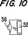
エラストマー24は、インサート22と同様の形状を有するが、寸法は明らかになる理由とは異なる。エラストマー24は、外側に突出する一対のタブ52及び54を備えた本体を有する。タブ52は、凹所32の深い部分36に受けられる形状である。タブ54は、凹所34に受けられる。組立られた固定ピンにおいて、エラストマー24は、ケーシング20とインサート22との間に挿入される(図2及び図13)。エラストマー24の本体は、長手方向に延びており、インサートのスロット50に受けられるインサート側の長手方向のリブ56と、ケーシングのリブ44を受けるためにケーシング側に長手方向58とを有する。
【0021】
ケーシングとインサートの組立工程が図14ないし図17に示されている。ケーシングとインサートを同時に組み立てるために、インサート22は、凹所32の深い部分36に長いタブ46を挿入し、ケーシングに関してインサートを傾斜することによってケーシング20に関して固定する関係で嵌合される。これによて短いタブ48が矢印60によって支持されるようにケーシングの当接部42を越え、凹所34に受けられる。インサート22を図15に示すように直立させるとき、タブ46が深い凹所36に配置され、ケーシング20とインサート22の本体は、平行な関係になる。インサート22がタブ46が凹所32の浅い部分38に配置され、固定当接部40に当たるように矢印62の方向で図16に示すように外側に移動される。同時にタブ48は、それが固定当接部42に接触するように外側に移動する。この方法でタブ46及び48は、タブが当接部40及び42に接触するように凹所32及び34にかみあうように受けられる。それによってケーシング20及びインサート22は、その間に空隙21を形成する。
【0022】
組立てられたケーシング及びインサートは、それらの間に形成された空隙21にエラストマー部材24を導入することによって、いっしょにしっかりと固定される。またエラストマー24は、本体に隣接するケーシングの凹所32及び34の部分を充填しケーシング及びインサートの間の空隙に充填される(図17)。ケーシングとインサートとの間にエラストマー部材を挿入することは、インサートが凹所32の深い部分36にすべり、ゆるみ、外れることを防止する。係合を改善するためにエラストマー24の長手方向のスロット58は、ケーシングの長手方向のリブ44を受け、エラストマー24の長手方向リブ56は、インサートの長手方向のスロット50に受けられる。これらのリブとスロットのかみ合った関係によりエラストマーの側方の動きを防止し、エラストマーと金属部品との間の係合部分に大きな表面積を提供する。
【0023】
好ましい実施の形態においてエラストマーは、ケーシング側のスロットと、インサート側のリブとを有するが、ケーシング及びインサートのスロットとリブとの対応する変化を逆転することができることを理解すべきである。さらに、これらの部品の係合を向上する他の手段は、本発明の範囲内にあることを理解すべきである。例えば、中実のリブ及びスロットの代わりに一連の突出部分及びかみ合い凹所を使用することができる。
【0024】
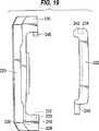
ケーシング及びインサートの組立体の構造、すなわち、凹所及びタブは平行関係で行かれるとき連続的な組立、固定及び拘束を可能にする一連の構成に配置さすることができる。図18ないし図21は、ケーシング及びインサートの好ましい実施の形態を示す。これらの図面において、部品は図4と同様の正面図に示されている。
【0025】
図18の第2の好ましい実施の形態において、ケーシング120は、アーム128及び130に組立体のタブ146及び148を備えている。組立体タブ146及び148は、それぞれ凹所132及び134に受けられる。このピンのインサート及びケーシングの組立体は、第1の実施の形態の組立の順序と同様の順序で起こる。インサート122は、タブ146が凹所132の深い部分136に挿入されるように傾斜している。これは、ケーシングの当接部142をタブ148が越え、凹所134にうけられることができるようにする。インサート122が直立したとき、タブ146は、深い凹所136及びケーシング126の本体内に配置され、インサート122は、平行な関係にされる。インサート122は、タブ146が凹所132の浅い部分136に配置され、固定当接部140に当接するようにケーシング本体に関して外側に移動する。同時にタブ148は、固定当接部142にあたるように移動する。この方法によって、タブ146及び148は、タブが当接部140及び142に当たるように凹所132及び134にかみあうように受けられる。それらは、互いに向かって及び互いに離れる方向に移動することを除いていかなる方向に移動することも拘束される。ケーシング120及びインサート122の間に形成された空隙にエラストマーが上述したように配置され、部品を所定の位置に固定する。
【0026】
図19に示す第3の好ましい実施の形態において、ケーシング220は、アーム230上に組立体タブ248とアーム228上に凹所232とを有する。それに対応して、インサート222は、一端に凹所234と、他端に組立体タブ246を備えている。もちろんタブ及び凹所の構成は、アーム228及び230で反転することができる。組立の順序は、タブ246を凹所232の深い部分236に挿入するためにインサート222を傾斜することから始まる。これによりタブ248がインサートの当接部242を越えることができ、凹所232に受けられる。インサート222がまっすぐになると、タブ246は、深い凹所236内に配置され、ケーシング220及びインサート222の本体が平行な関係になる。次にインサート222は、タブ246が凹所232の浅い部分238に配置され、固定当接部240に当たるようにケーシング本体220に対して外側に移動される。同時にタブ248は、固定当接部242にあたる。この方法において、タブ246及び248は、タブが当接部240及び242にそれぞれ当たるように凹所232及び234にかみあうように受けられる。ケーシング及びインサートは、互いに向かうように及び互いに離れるように移動することを除いてどの方向に移動することも拘束される。ケーシング120とインサート122との間に形成された空隙には、部品を所定の位置に固定するためにエラストマーが上述したように間に配置される。
【0027】
第4及び第5の好ましい実施の形態は、わずかに異なる凹所と構造を呈する。これらの実施の形態において、タブ及び凹所は、等しい長さと深さである。なぜならば、タブは、側方から凹所に挿入されるからである。これらの実施の形態における共通の特徴は、断面で見て、Lの一方の脚部が挿入領域として作用し、Lの他方の脚部が固定当接部を含む固定領域として作用するように凹所はL形状である。
【0028】
特に、図20において、ケーシング320は、解放端部333及び335を有する凹所332及び334、固定当接部340及び342を有する。図20Aで分かるように、開放端部333及び335は、固定当接部340及び342に関して傾斜、特に直角な関係である。インサート322は、端部に組立体タブ346及び348を有する。部品を一緒に組み立てるために、インサート322は、タブ346及び348が開放溝333及び335にそれぞれ挿入されるように配置される。インサート322は、タブ346及び348が固定当接部340及び342に当接するまでケーシング320に対して移動される。この実施の形態において、インサート322及びケーシング320は、組立処理を通して平行な関係にある。このケーシング及びインサートは、互いに向かい及び離れる方向に移動することを除いていかなる方向にも移動することが拘束される。ケーシング320及びインサート322の間に形成された空隙には、部品を所定の位置に固定するように叙述したようにエラストマーが挿入される。
【0029】
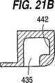
図21に示すように第5の好ましい実施の形態において、ケーシング420は、凹所432及び434を有し、この凹所432及び434は、開放端部または溝433及び435及び固定当接部440及び442を有する。凹所の開放溝がケーシングの同じ側にある図20に対して、図21の溝は、反対側に開放端部を有する。すなわち、溝435は、ケーシング420の一方の側に開放しており、溝433は他方の側に開放している。溝433及び435は、固定当接部440及び442に傾斜した関係で好ましくは直角な関係である。インサート422はその端部に組立体タブ446及び448を含む。この部品を一緒に組み立てるために、インサート422は、タブを開放溝433及び435に挿入するためにケーシング420の両側にタブ446及び448が配置されるように回転される。インサート422は、タブ446及び448が固定固定当接部440及び442にそれぞれ当接するまでケーシング420に関して外側に移動される。この実施の形態において、インサート422及びケーシング420は、組立工程を通して平行な関係にあるが、インサート422は、側方の軸線の周りにケーシング420に対して回転される。一旦組み立てられると、ケーシング及びインサートは、互いに向かう方向及び離れるように移動することを除いてどの方向への移動も拘束される。ケーシング420及びインサート422の間に形成された空隙に部品を所定の位置に固定するように上述したようにエラストマーが間に配置される。
【0030】
すべての実施の形態において、エラストマーは、3つの実施の形態の固定力を増大するために組立られたピンを予め負荷を加えるようにケーシングとインサートとの間の空隙より大きい寸法である。このピンは、従来のサンドウイッチピンに比較してピンの圧縮範囲にわたってポイントとアダプタを一緒に保持する大きな平均的な力を提供する。さらに、このピンは、組立体に容易に駆動される。なぜならば、ケーシング及びインサートは駆動されながら、基本的には平行な関係にあるからである。これは、始めにいっしょに絞られ、離れて駆動を困難にする従来のピンのくさび動作を妨げる。圧縮可能なエラストマーを有する現在のピンは、空隙より大きな寸法であり、絞りばめで押される剛性ピンであるので、過度の打撃や特別の配置治具を必要としない。
【0031】
したがって、完全に組み立てられた固定ピンの部品は、緊密に一緒に製造され、整列固定開口に挿入する一体の部品を呈する。エラストマーが構造的な拘束手段によって所定の位置に保持されるので、エラストマーを金属部品に結合する接着剤の必要性はない。したがって、腐食的な環境において部品が使用されるとき接着剤の安定性または耐久性の問題はない。また、これら3つの部品の緊密に組み立てられた関係は、大きな力が加えられている間、部品がゆるむことなく、放出されるか、失われることがないことを保証する。
【0032】
本発明の固定ピンは、ある外側及び表面を有するものとして図面に示されている。この特定の輪郭及び表面は、対応する外側の輪郭を有する整列した固定装置とともに使用されるようになっている。本発明の好ましい実施の形態は、浚渫設備用の固定ピンであるが、ケーシング及びインサートの外側の輪郭及び表面は、本発明の範囲から逸脱することなく変化することができる。
【0033】
固定ピンの好ましい実施の形態を掘削装置、特に浚渫装置とともに使用することを説明したが、固定ピンの構造及びその動作の原理は、整列した組立体の開口を有する部品を一緒に保持するために使用することができることは理解されよう。
【0034】
これまでの詳細な説明から、当業者による多数の本発明の変更、適合及び改造があることは明らかである。しかしながら、本発明の精神から逸脱しないこれらの変化は請求の範囲によってのみ制限される範囲内にあると考慮される。
【図面の簡単な説明】
【図1】 本発明の好ましい実施の形態による固定ピンとともに組み立てられるアダプタ及びポイントの拡大部分斜視図である。
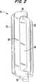
【図2】 所定位置にエラストマーが組み立てられた本発明の固定ピンの斜視図である。
【図3】 エラストマーのない状態で示す図1の固定ピンの斜視図である。
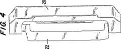
【図4】 図3の固定ピンの前側の後面図である。
【図5】 図3の固定ピンの後側の後面図である。
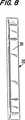
【図6】 図3の固定ピンの端面図である。
【図7】 図3の固定ピンの正面図である。
【図8】 図3の固定ピンの一方の側の正面図である。
【図9】 エラストマーの一方の側の正面図であり、他方の側は、図13に示されている。
【図10】 図9のエラストマーの端面図である。
【図11】 図9のエラストマーのリブが形成された側の正面図である。
【図12】 図9のエラストマーのスロットを備えた側の側面図である。
【図13】 図2の固定ピン部品の分解組立体である。
【図14】 ケーシングへのインサートの係合を示す図2の固定ピンの組立体の図面である。
【図15】 インサートの両端のケーシングへの組み立てたを示す図2の固定ピンの組立図面である。
【図16】 ケーシングへの嵌合されたインサートを示す図2の固定ピンの組立体である。
【図17】 ケーシングに完全に組み立てられ、所定の位置にエラストマーを有するインサートを示す図12の固定ピンの組立図である。
【図18】 固定ピンの第2の好ましい実施の形態によるケーシング及びインサートの拡大組立体である。
【図19】 固定ピンの第3の好ましい実施の形態によるケーシング及びインサートの拡大組立体である。
【図20】 固定ピンの第4の好ましい実施の形態によるケーシング及びインサートの拡大組立体である。図20Aは、図20の線20A−20Aに沿った断面図である。
【図21】 固定ピンの第5の実施の形態によるケーシング及びインサートの分解組み立て図である。図21Aは、図21の線21A−21Aに沿った断面図である。図21Bは、図21の線21B−21Bに沿った断面図である。[0001]
BACKGROUND OF THE INVENTION
The present invention relates to an improved fixing pin for use at the attachment point of an adapter for use in all types of excavation equipment, in particular dredging equipment.
[0002]
[Prior art]
In the mining and construction industry, dredging equipment has a series of spaced teeth that are attached to the edge of the dredger hole (bucket lip). The teeth project forward to engage and break the material collected in the bucket. As can be appreciated, the teeth are exposed to high friction conditions and become significantly worn.
[0003]
To minimize the dumping of many raw materials from used replacement parts, the teeth are manufactured from multiple parts including adapters and points. This adapter is attached to the lip of the bucket and has a nose protruding forward. The point has a front pierced end and forms a rear open socket that receives the adapter nose. This point thus wraps around the adapter nose. Thus, the points are subject to wear and often have to be replaced. This point must be securely fixed to the adapter to withstand heavy loads, but must be easily set and released to replace the point in this area. The fixation pin must also withstand the environmental conditions that expose the teeth, including potential corrosion conditions such as working in salt water.
[0004]
Typically, the point and adapter nose are provided with complementary securing openings for receiving securing pins. A wide range of point-adapter nose shapes are possible. Several examples are shown in US Pat. No. 5,469,648, which is incorporated by reference in its entirety. When assembling the parts, the openings are aligned so that they can receive the fixing pins. In some cases, a rigid pin is used in combination with an elastic retaining member. The keeper member holds the pin in the opening and tightens the point engagement on the adapter nose. In another configuration, a sandwich pin is used without using a separate keeper member. Typically, a sandwich pin has a pair of rigid portions that are combined with an elastic portion in a unitary structure so that the pin attaches the point in place and acts to tighten the connection of the parts.
[0005]
While sandwich pins offer the advantage of using a single fixed component, the problem arises of forming a pin with a structure that has a binding force and durability. For example, the elastic part and the metal part are fixed with an adhesive to keep the pin as one piece. Therefore, there is great reliability in the joint portion between the parts due to adhesion. However, the adhesive is affected in a corrosive environment, and the fixing pin is detached and the pin is lost.
[0006]
During use, the pins are continuously inserted and the metal part is periodically moved relative to the elastic part. This elastic material loses its elasticity through fatigue failure due to continuous loading and does not swell much to keep the pins in aligned openings. As a result of the loss of the pin, the point is lost, exposing the adapter to wear out prematurely and exposing the point to possible damage to the device.
[0007]
Also, the continuous load adversely affects the adhesive bond between the elastic part and the metal part, and causes a failure due to fatigue of the bonded part.
[0008]
In most fixed pin assemblies that use sandwich pins, the pin elastic members must expand to maintain a tight fit and prevent pin loss in the aligned assembly openings. Therefore, to maximize the life of the part, the opening formed through the point and adapter nose, regardless of whether the opening is vertical or horizontal, the pin is initially in a very tight configuration It is comprised so that it may be inserted.
[0009]
Most sandwich pins are manufactured by inserting a rigid metal member into a mold, coating the metal member with an adhesive, and injection molding the elastomeric member to maintain the pin elastomeric and synthetic members Is done. This injection molding method requires a large amount of labor because it is necessary to manually place a metal part on the mold, mold it, and remove the part from the mold. In this manufacturing method, in addition to the manual positioning, molding, and removal processes, it is necessary to clean the parts coated with the undercoat and adhesive on the metal parts, and to clean the flash from the parts and metal debris.
[0010]
US Pat. No. 5,469,648 to Jones et al. Shows an excavating tooth attached with a sandwich fixing pin. The fixation pin includes a rigid casing having one or two cavities that receive the elastic material and a metal cover that overlies the elastic material to prevent premature wear. However, the cavity that receives this cover is too shallow to hold the cover in use. As a result, an adhesive or the like is necessary so that the cover is not lost. Adhesive failure due to corrosion or fatigue results in pin failure and loss of points or other wear parts.
[0011]
U.S. Pat. No. 2,772,492 to Murtaugh shows a retaining key that attaches a bucket tooth adapter to a bucket lip. The holding key has a C-shaped member, a wedge, and an elastic pad disposed therebetween. The wedge has a protrusion that is received in a recess that opens laterally on one side. As a result, there is no means to restrain the wedge laterally within the casing. Therefore, it can slip out of the side of the casing during installation and use and can be lost.
[0012]
[Means for Solving the Problems]
The present invention relates to an improved locking pin for use in attaching a wear member, such as an adapter point, to a base and with a dredge. The pin has two cooperating steel parts, a casing, an insert and an elastomer part. The casing and insert have longitudinal bodies that are parallel and spaced from each other. The two steel parts are assembled together in a special order so that they are held firmly together and constrained from moving in one direction, ie towards and away from each other. The elastomeric member is placed between steel parts that are assembled so that the metal parts are elastically biased away from each other so that the parts are tightly constrained in all directions. The tight construction eliminates the need for an adhesive to bond the elastomer to the metal. Thus, the pins can be used without the risk of the adhesive becoming ineffective due to fatigue or corrosive environments.
[0013]
By eliminating the need for adhesives, there are at least three steps: inserting the metal part into the mold, coating the metal part with the adhesive, and subbing, flushing and sprue the adhesive after molding. It is possible to facilitate the manufacture of the parts by eliminating the step of cleaning this portion and the step of cleaning. Since these entire processes are usually done by hand, time and effort are saved by manufacturing the parts independently and assembling them together. The elastomeric members of the present invention are preferably manufactured automatically in a large automatic line, which can produce parts that do not require cleaning and finishing using high quality jigs.
[0014]
These and other features of the present invention will be more fully understood from the following detailed section of the invention with reference to the accompanying drawings.
[0015]
DETAILED DESCRIPTION OF THE INVENTION
Hereinafter, an embodiment of the present invention will be described in detail with reference to the drawings.
[0016]
The present invention relates to an improved fixing pin for fixing together two parts with aligned fixing openings. For ease of explanation, it will be described in an application which is an exemplary concept for securing the adapter and tooth tip of the scissors device together. It will be appreciated that the improved locking pin described herein can be used in a variety of other facilities. The operation of the scissors device allows the teeth and the fixing pin to take many different orientations. The parts of the fixation pin define an absolute orientation or direction with respect to each other. The three main direction criteria used in this description are the longitudinal direction of the pin part and the first and second lateral directions perpendicular to each other and to the longitudinal direction. Furthermore, the fixing pin and its components will be described with reference to relative directions such as front, back, side and bottom. These relative directions are arbitrarily selected to facilitate the description with respect to the drawings, and do not necessarily coincide with the orientation that the pins take in the work environment.
[0017]
In the preferred embodiment of the present invention (FIGS. 1-17), the
[0018]
The
[0019]
The
[0020]
[0021]
The assembly process of the casing and the insert is shown in FIGS. To assemble the casing and insert simultaneously, the
[0022]
The assembled casing and insert are secured together by introducing an
[0023]
In preferred embodiments, the elastomer has casing side slots and insert side ribs, but it should be understood that the corresponding changes in the casing and insert slots and ribs can be reversed. Furthermore, it should be understood that other means for improving the engagement of these parts are within the scope of the present invention. For example, a series of protrusions and mating recesses can be used instead of solid ribs and slots.
[0024]
The structure of the casing and insert assembly, i.e., the recesses and tabs, can be arranged in a series of configurations that allow for continuous assembly, locking and restraining when done in a parallel relationship. 18 to 21 show a preferred embodiment of the casing and insert. In these drawings, the components are shown in a front view similar to FIG.
[0025]
In the second preferred embodiment of FIG. 18, the
[0026]
In the third preferred embodiment shown in FIG. 19, the
[0027]
The fourth and fifth preferred embodiments exhibit slightly different recesses and structures. In these embodiments, the tabs and recesses are of equal length and depth. This is because the tab is inserted into the recess from the side. A common feature of these embodiments is that when viewed in cross section, one leg portion of L acts as an insertion region, and the other leg portion of L acts as a fixing region including a fixed contact portion. The place is L-shaped.
[0028]
In particular, in FIG. 20, the
[0029]
As shown in FIG. 21, in a fifth preferred embodiment, the
[0030]
In all embodiments, the elastomer is sized larger than the gap between the casing and the insert so as to preload the assembled pins to increase the fixing force of the three embodiments. This pin provides a greater average force to hold the point and adapter together over the pin compression range compared to a conventional sandwich pin. Furthermore, this pin is easily driven into the assembly. This is because the casing and the insert are basically in a parallel relationship while being driven. This hinders the conventional pin wedge motion, which is initially squeezed together, making it difficult to drive away. Current pins with compressible elastomers are larger in size than the air gap and are rigid pins that are pressed with a tight fit, so that no excessive hitting or special placement jigs are required.
[0031]
Thus, the fully assembled parts of the fixing pin are manufactured together closely and present an integral part that inserts into the alignment fixing opening. Since the elastomer is held in place by structural restraining means, there is no need for an adhesive to bond the elastomer to the metal part. Thus, there is no problem with the stability or durability of the adhesive when the part is used in a corrosive environment. Also, the tightly assembled relationship of these three parts ensures that the parts are not released or lost without loosening while a large force is applied.
[0032]
The fixing pin of the present invention is shown in the drawings as having an outer side and a surface. This particular profile and surface is intended to be used with an aligned fixation device having a corresponding outer profile. Although the preferred embodiment of the present invention is a anchoring pin for dredging equipment, the outer contours and surfaces of the casing and insert can be varied without departing from the scope of the present invention.
[0033]
Although the preferred embodiment of the fixing pin has been described for use with a drilling device, in particular a dredging device, the structure of the fixing pin and the principle of its operation are for holding together parts having aligned assembly openings. It will be understood that it can be used.
[0034]
From the foregoing detailed description, it should be apparent that there are a number of variations, adaptations and modifications of the present invention by those skilled in the art. However, these variations which do not depart from the spirit of the invention are considered to be within the scope limited only by the claims.
[Brief description of the drawings]
FIG. 1 is an enlarged partial perspective view of an adapter and point assembled with a fixing pin according to a preferred embodiment of the present invention.
FIG. 2 is a perspective view of a fixing pin of the present invention in which an elastomer is assembled at a predetermined position.
FIG. 3 is a perspective view of the fixing pin of FIG. 1 shown without an elastomer.
4 is a rear view of the front side of the fixing pin of FIG. 3;
FIG. 5 is a rear view of the rear side of the fixing pin of FIG. 3;
6 is an end view of the fixing pin of FIG. 3. FIG.
7 is a front view of the fixing pin of FIG. 3. FIG.
8 is a front view of one side of the fixing pin of FIG. 3;
FIG. 9 is a front view of one side of the elastomer, the other side being shown in FIG.
10 is an end view of the elastomer of FIG. 9. FIG.
FIG. 11 is a front view of the side on which the elastomeric ribs of FIG. 9 are formed.
12 is a side view of the side with the elastomeric slot of FIG. 9. FIG.
FIG. 13 is an exploded assembly of the fixing pin part of FIG. 2;
14 is a drawing of the assembly of the fixation pin of FIG. 2 showing the engagement of the insert to the casing.
15 is an assembly drawing of the fixing pin of FIG. 2 showing the assembly of the both ends of the insert into the casing.
16 is an assembly of the fixation pin of FIG. 2 showing the insert fitted to the casing.
17 is an assembly view of the fixation pin of FIG. 12 showing the insert fully assembled into the casing and having an elastomer in place.
FIG. 18 is an enlarged assembly of casing and insert according to a second preferred embodiment of a fixation pin.
FIG. 19 is an enlarged assembly of casing and insert according to a third preferred embodiment of a fixation pin.
FIG. 20 is an enlarged assembly of casing and insert according to a fourth preferred embodiment of a fixation pin. 20A is a cross-sectional view taken along line 20A-20A of FIG.
FIG. 21 is an exploded view of the casing and the insert according to the fifth embodiment of the fixing pin. 21A is a cross-sectional view taken along line 21A-21A of FIG. 21B is a cross-sectional view taken along line 21B-21B in FIG.
Claims (17)
Translated fromJapanese外側部分と内側部分とを形成する前記本体部分の端部に設けられ側方に延びるアームとを有し、前記アームの各々は、インサート部材のタブを受けるために内側部分に設けられた組立凹所を有し、各前記凹所の各々は、互いに向かい離れる方向を除いてすべての方向に前記ケーシングに対してインサート部材の動きを拘束するように前記アームの自由端部及び側面の固定当接部によって形成される、固定ピン組立体用のケーシング。A longitudinal body part;
A laterally extending arm provided at an end of the body portion forming an outer portion and an inner portion, each of the arms being an assembly recess provided in the inner portion for receiving a tab of an insert member Each of the recesses has a fixed abutment on the free end and side of the arm so as to constrain the movement of the insert member relative to the casing in all directions except in a direction away from each other. A casing for the fixed pin assembly formed by the section.
前記本体部分の各端部に形成されたインサートタブとを有し、前記インサートタブは、前記ケーシングに関して垂直方向及び側方の双方に前記インサートを拘束するために前記ケーシングの対応する凹所に挿入されるようになっている、固定ピン組立体用の剛性のインサート部品。An insert adapted to be assembled to a rigid casing includes a longitudinal body portion having an engagement structure disposed along the body portion that engages an elastomeric part of a fixed pin assembly;
Insert tabs formed at each end of the body portion, the insert tabs being inserted into corresponding recesses in the casing to restrain the insert both vertically and laterally with respect to the casing. A rigid insert part for a fixed pin assembly.
前記長手方向に延びるとともに第2の組立体構造を有する本体を有する第2の剛性部材であって、前記第1の剛性部材に組み立てられ、前記長手方向に拘束され、前記第1の組立体構造と前記第2の組立体構造を協働させることによって前記第1の剛性部材に対して長手方向及び第1の側方の方向及び第2の側方の方向に拘束される第2の剛性部材と、
前記第1の剛性部材と前記第2の剛性部材とを離れるように弾性的に偏倚するために前記第1の剛性部材と前記第2の剛性部材との間に配置されるエラストマー部材とを有する、前記固定ピンを整列した固定開口に挿入することによって一緒に結合する固定ピン。A first rigid member having a body extending longitudinally and including a first assembly structure;
A second rigid member having a body extending in the longitudinal direction and having a second assembly structure, assembled to the first rigid member and constrained in the longitudinal direction, the first assembly structure And a second rigid member that is constrained in a longitudinal direction, a first lateral direction, and a second lateral direction relative to the first rigid member by cooperating with the second assembly structure. When,
An elastomeric member disposed between the first rigid member and the second rigid member for elastically biasing the first rigid member and the second rigid member away from each other; A fixing pin that is joined together by inserting the fixing pins into aligned fixing openings.
Applications Claiming Priority (3)
| Application Number | Priority Date | Filing Date | Title |
|---|---|---|---|
| US08/993,173 | 1997-12-18 | ||
| US08/993,173US6030143A (en) | 1997-12-18 | 1997-12-18 | Locking pin for excavating equipment |
| PCT/US1998/026406WO1999030875A1 (en) | 1997-12-18 | 1998-12-11 | Improved locking pin for excavating equipment |
Publications (2)
| Publication Number | Publication Date |
|---|---|
| JP2002508482A JP2002508482A (en) | 2002-03-19 |
| JP3839255B2true JP3839255B2 (en) | 2006-11-01 |
Family
ID=25539187
Family Applications (1)
| Application Number | Title | Priority Date | Filing Date |
|---|---|---|---|
| JP2000538833AExpired - LifetimeJP3839255B2 (en) | 1997-12-18 | 1998-12-11 | Improved fixing pin for drilling rig |
Country Status (19)
| Country | Link |
|---|---|
| US (1) | US6030143A (en) |
| EP (1) | EP1054755B1 (en) |
| JP (1) | JP3839255B2 (en) |
| KR (1) | KR100396169B1 (en) |
| CN (1) | CN1122128C (en) |
| AT (1) | ATE337139T1 (en) |
| AU (1) | AU748126B2 (en) |
| BR (1) | BR9813675A (en) |
| CA (1) | CA2315098C (en) |
| DE (1) | DE69835698T2 (en) |
| DK (1) | DK1054755T3 (en) |
| ES (1) | ES2272016T3 (en) |
| MX (1) | MXPA00005975A (en) |
| NO (2) | NO20003134L (en) |
| NZ (1) | NZ505229A (en) |
| PT (1) | PT1054755E (en) |
| TR (1) | TR200001930T2 (en) |
| TW (1) | TW397882B (en) |
| WO (1) | WO1999030875A1 (en) |
Families Citing this family (32)
| Publication number | Priority date | Publication date | Assignee | Title |
|---|---|---|---|---|
| US6735890B2 (en)* | 2001-07-06 | 2004-05-18 | Esco Corporation | Wear assembly |
| ATE452250T1 (en)* | 1996-11-15 | 2010-01-15 | Combi Wear Parts Ab | TOOTH ARRANGEMENT |
| ES2146541B1 (en) | 1998-06-08 | 2001-04-01 | Metalogenia Sa | DEVICE FOR THE COUPLING OF EXCAVATOR TEETH. |
| ES2146174B1 (en) | 1998-07-03 | 2002-01-16 | Metalogenia Sa | COUPLING FOR EXCAVATOR AND SIMILAR TEETH. |
| ES2158805B1 (en) | 1999-10-01 | 2002-04-01 | Metalogenia Sa | IMPROVEMENTS IN THE COUPLINGS FOR MACHINE TEETH FOR GROUND MOVEMENT. |
| US6993861B2 (en)* | 2001-07-06 | 2006-02-07 | Esco Corporation | Coupling for excavating wear part |
| US6393739B1 (en) | 2001-08-16 | 2002-05-28 | G. H. Hensley Industries, Inc. | Excavating tooth point and adapter apparatus |
| US6729052B2 (en) | 2001-11-09 | 2004-05-04 | Esco Corporation | Assembly for securing an excavating tooth |
| ES2346698T3 (en) | 2002-09-19 | 2010-10-19 | Esco Corporation | WEAR AND BLOCK SET FOR AN EXCAVATION SPOON. |
| FR2846017B1 (en)* | 2002-10-17 | 2005-02-11 | Afe Metal | DEVICE FOR CONNECTING COUPLING BETWEEN WEAR PARTS TO THE END OF TOOLS RECEPTACLES USED ON PUBLIC WORKS MACHINERY |
| CA2466768A1 (en)* | 2004-05-10 | 2004-10-22 | Quality Steel Foundries Ltd. | Locking assembly for ground engaging tools |
| PL3263776T3 (en) | 2006-03-30 | 2022-01-17 | Esco Group Llc | Wear assembly |
| US7603799B2 (en)* | 2006-05-11 | 2009-10-20 | Hensley Industries, Inc. | Cammed connector pin assembly and associated excavation apparatus |
| US20080005940A1 (en)* | 2006-07-10 | 2008-01-10 | Esco Corporation | Assembly for securing a wear |
| CA2612341A1 (en)* | 2007-11-27 | 2009-05-27 | Black Cat Blades Ltd. | Ground engaging tool blade |
| US7681341B2 (en) | 2008-02-15 | 2010-03-23 | Hensley Industries, Inc. | Double cam taper lock connector pin apparatus |
| CA2721781C (en)* | 2008-04-18 | 2013-12-03 | Cqms Pty Ltd | A lock assembly for an excavator wear member |
| WO2011088511A1 (en) | 2010-01-20 | 2011-07-28 | Bradken Resources Pty Limited | Excavation tooth assembly |
| US8890672B2 (en) | 2011-08-29 | 2014-11-18 | Harnischfeger Technologies, Inc. | Metal tooth detection and locating |
| US8336233B1 (en) | 2012-04-06 | 2012-12-25 | Gaetano Lombardo | Wear plate assembly |
| US9388553B2 (en)* | 2013-05-31 | 2016-07-12 | Caterpillar Inc. | Retainer systems for ground engaging tools |
| WO2015010159A1 (en)* | 2013-07-23 | 2015-01-29 | Bradken Uk Limited | A lock for an excavation tooth assembly |
| CN104358287B (en)* | 2014-10-16 | 2017-04-05 | 广西柳工机械股份有限公司 | Locking pin |
| US9611625B2 (en) | 2015-05-22 | 2017-04-04 | Harnischfeger Technologies, Inc. | Industrial machine component detection and performance control |
| US9670648B2 (en) | 2015-08-10 | 2017-06-06 | Caterpillar Inc. | Replaceable tip systems for a tine |
| AU2016354542B2 (en) | 2015-11-12 | 2019-03-07 | Joy Global Surface Mining Inc | Methods and systems for detecting heavy machine wear |
| US9840829B2 (en)* | 2015-12-01 | 2017-12-12 | Srj, Inc. | Flex pin |
| CN109415885A (en) | 2016-07-06 | 2019-03-01 | 成矿研究科技有限公司 | The abrasion of tool for earth mover or protection system and corresponding pin |
| US10400427B2 (en) | 2017-05-31 | 2019-09-03 | Srj, Inc. | Flex pin |
| TW202033863A (en)* | 2018-10-31 | 2020-09-16 | 美商艾斯克集團有限責任公司 | Wear assembly |
| US10428494B1 (en) | 2018-12-07 | 2019-10-01 | Pasquale Lombardo | Wear plate assembly with two-part key assembly |
| EP4118273A4 (en) | 2020-03-09 | 2024-04-03 | Pasquale Lombardo | Corner wear plate assembly |
Family Cites Families (11)
| Publication number | Priority date | Publication date | Assignee | Title |
|---|---|---|---|---|
| US2772492A (en)* | 1953-02-12 | 1956-12-04 | American Brake Shoe Co | Retainer pins for dipper teeth |
| US2870667A (en)* | 1954-07-08 | 1959-01-27 | American Brake Shoe Co | Retaining key for dipper tooth parts having resilient pad |
| US2982035A (en)* | 1958-04-28 | 1961-05-02 | Thomas C Whisler | Excavator tooth |
| BR6308410D0 (en)* | 1972-10-31 | 1974-09-05 | Poclain Sa | REPLACEMENT TOOTH FOR PUBLIC WORKS INSTRUMENT, ADMITTING A PRIVATE KEY |
| US4155665A (en)* | 1976-03-29 | 1979-05-22 | Caterpillar Tractor Co. | Resilient retention key for replaceable ripper teeth |
| DE2713227C2 (en)* | 1977-03-25 | 1983-08-04 | O & K Orenstein & Koppel Ag, 1000 Berlin | Detachable fastening of an excavator tooth provided with a sleeve at the rear on a tooth holder engaging in the sleeve |
| US4282665A (en)* | 1980-02-06 | 1981-08-11 | Dresser Industries, Inc. | Excavator tooth assembly |
| US4335532A (en)* | 1980-04-28 | 1982-06-22 | Esco Corporation | Excavating tooth |
| US4481728A (en)* | 1981-12-01 | 1984-11-13 | Abex Corporation | Dipper tooth tip and adapter |
| US4446638A (en)* | 1982-12-27 | 1984-05-08 | Abex Corporation | Dipper tip retaining pin |
| US5469648A (en)* | 1993-02-02 | 1995-11-28 | Esco Corporation | Excavating tooth |
- 1997
- 1997-12-18USUS08/993,173patent/US6030143A/ennot_activeExpired - Lifetime
- 1998
- 1998-12-11KRKR10-2000-7006715Apatent/KR100396169B1/ennot_activeExpired - Lifetime
- 1998-12-11JPJP2000538833Apatent/JP3839255B2/ennot_activeExpired - Lifetime
- 1998-12-11DKDK98963872Tpatent/DK1054755T3/enactive
- 1998-12-11NZNZ505229Apatent/NZ505229A/ennot_activeIP Right Cessation
- 1998-12-11PTPT98963872Tpatent/PT1054755E/enunknown
- 1998-12-11AUAU19109/99Apatent/AU748126B2/ennot_activeExpired
- 1998-12-11BRBR9813675-5Apatent/BR9813675A/ennot_activeIP Right Cessation
- 1998-12-11CNCN98813692Apatent/CN1122128C/ennot_activeExpired - Lifetime
- 1998-12-11EPEP98963872Apatent/EP1054755B1/ennot_activeExpired - Lifetime
- 1998-12-11CACA002315098Apatent/CA2315098C/ennot_activeExpired - Lifetime
- 1998-12-11TRTR2000/01930Tpatent/TR200001930T2/enunknown
- 1998-12-11ESES98963872Tpatent/ES2272016T3/ennot_activeExpired - Lifetime
- 1998-12-11ATAT98963872Tpatent/ATE337139T1/enactive
- 1998-12-11MXMXPA00005975Apatent/MXPA00005975A/enactiveIP Right Grant
- 1998-12-11WOPCT/US1998/026406patent/WO1999030875A1/enactiveIP Right Grant
- 1998-12-11DEDE69835698Tpatent/DE69835698T2/ennot_activeExpired - Lifetime
- 1998-12-18TWTW087121195Apatent/TW397882B/ennot_activeIP Right Cessation
- 2000
- 2000-06-16NONO20003134Apatent/NO20003134L/ennot_activeApplication Discontinuation
- 2000-06-19NONO20003187Apatent/NO20003187L/enunknown
Also Published As
| Publication number | Publication date |
|---|---|
| AU1910999A (en) | 1999-07-05 |
| NO20003134L (en) | 2000-07-31 |
| NO20003134D0 (en) | 2000-06-16 |
| CA2315098A1 (en) | 1999-06-24 |
| CN1286656A (en) | 2001-03-07 |
| DK1054755T3 (en) | 2007-01-02 |
| NO20003187D0 (en) | 2000-06-19 |
| BR9813675A (en) | 2001-12-26 |
| CN1122128C (en) | 2003-09-24 |
| DE69835698D1 (en) | 2006-10-05 |
| TR200001930T2 (en) | 2000-12-21 |
| ATE337139T1 (en) | 2006-09-15 |
| ES2272016T3 (en) | 2007-04-16 |
| EP1054755A1 (en) | 2000-11-29 |
| JP2002508482A (en) | 2002-03-19 |
| EP1054755B1 (en) | 2006-08-23 |
| PT1054755E (en) | 2007-01-31 |
| HK1034222A1 (en) | 2001-10-19 |
| KR100396169B1 (en) | 2003-08-27 |
| NO20003187L (en) | 2000-07-26 |
| AU748126B2 (en) | 2002-05-30 |
| EP1054755A4 (en) | 2001-01-17 |
| US6030143A (en) | 2000-02-29 |
| TW397882B (en) | 2000-07-11 |
| DE69835698T2 (en) | 2007-08-16 |
| MXPA00005975A (en) | 2002-09-18 |
| WO1999030875A1 (en) | 1999-06-24 |
| CA2315098C (en) | 2005-05-24 |
| NZ505229A (en) | 2002-03-28 |
| KR20010033277A (en) | 2001-04-25 |
Similar Documents
| Publication | Publication Date | Title |
|---|---|---|
| JP3839255B2 (en) | Improved fixing pin for drilling rig | |
| US6729052B2 (en) | Assembly for securing an excavating tooth | |
| JP5318574B2 (en) | Excavator wear assembly | |
| JP5242657B2 (en) | Material displacement device for displacing material, and wear member and connector assembly for constituting material displacement device | |
| JP4406367B2 (en) | Connecting device | |
| KR20080087843A (en) | Wear assembly | |
| JPH0619150B2 (en) | Excavator tooth assembly | |
| CN103608527B (en) | A kind of releasable securing apparatus for two mechanical parts | |
| CN102308050A (en) | Connection system and parts thereof for connecting wear elements and adapters of excavators and similar machines | |
| US4357765A (en) | Apparatus for securing overlapping portions of two digger tooth members together | |
| KR101067185B1 (en) | Removal device for attaching two mechanical parts | |
| CA2229112A1 (en) | Ground engaging tool components | |
| HK1034222B (en) | Improved locking pin for excavating equipment | |
| HK1074657B (en) | Assembly for securing a wear member | |
| HK1125428B (en) | A dredge cutterhead |
Legal Events
| Date | Code | Title | Description |
|---|---|---|---|
| A131 | Notification of reasons for refusal | Free format text:JAPANESE INTERMEDIATE CODE: A131 Effective date:20040507 | |
| A601 | Written request for extension of time | Free format text:JAPANESE INTERMEDIATE CODE: A601 Effective date:20040806 | |
| A602 | Written permission of extension of time | Free format text:JAPANESE INTERMEDIATE CODE: A602 Effective date:20040813 | |
| A02 | Decision of refusal | Free format text:JAPANESE INTERMEDIATE CODE: A02 Effective date:20051018 | |
| A521 | Request for written amendment filed | Free format text:JAPANESE INTERMEDIATE CODE: A523 Effective date:20060116 | |
| A911 | Transfer to examiner for re-examination before appeal (zenchi) | Free format text:JAPANESE INTERMEDIATE CODE: A911 Effective date:20060316 | |
| TRDD | Decision of grant or rejection written | ||
| A01 | Written decision to grant a patent or to grant a registration (utility model) | Free format text:JAPANESE INTERMEDIATE CODE: A01 Effective date:20060705 | |
| A61 | First payment of annual fees (during grant procedure) | Free format text:JAPANESE INTERMEDIATE CODE: A61 Effective date:20060802 | |
| R150 | Certificate of patent or registration of utility model | Free format text:JAPANESE INTERMEDIATE CODE: R150 | |
| FPAY | Renewal fee payment (event date is renewal date of database) | Free format text:PAYMENT UNTIL: 20090811 Year of fee payment:3 | |
| FPAY | Renewal fee payment (event date is renewal date of database) | Free format text:PAYMENT UNTIL: 20100811 Year of fee payment:4 | |
| FPAY | Renewal fee payment (event date is renewal date of database) | Free format text:PAYMENT UNTIL: 20110811 Year of fee payment:5 | |
| FPAY | Renewal fee payment (event date is renewal date of database) | Free format text:PAYMENT UNTIL: 20110811 Year of fee payment:5 | |
| FPAY | Renewal fee payment (event date is renewal date of database) | Free format text:PAYMENT UNTIL: 20120811 Year of fee payment:6 | |
| FPAY | Renewal fee payment (event date is renewal date of database) | Free format text:PAYMENT UNTIL: 20120811 Year of fee payment:6 | |
| FPAY | Renewal fee payment (event date is renewal date of database) | Free format text:PAYMENT UNTIL: 20130811 Year of fee payment:7 | |
| R250 | Receipt of annual fees | Free format text:JAPANESE INTERMEDIATE CODE: R250 | |
| R250 | Receipt of annual fees | Free format text:JAPANESE INTERMEDIATE CODE: R250 | |
| R250 | Receipt of annual fees | Free format text:JAPANESE INTERMEDIATE CODE: R250 | |
| R250 | Receipt of annual fees | Free format text:JAPANESE INTERMEDIATE CODE: R250 | |
| R250 | Receipt of annual fees | Free format text:JAPANESE INTERMEDIATE CODE: R250 | |
| R250 | Receipt of annual fees | Free format text:JAPANESE INTERMEDIATE CODE: R250 | |
| S111 | Request for change of ownership or part of ownership | Free format text:JAPANESE INTERMEDIATE CODE: R313111 | |
| R350 | Written notification of registration of transfer | Free format text:JAPANESE INTERMEDIATE CODE: R350 | |
| EXPY | Cancellation because of completion of term |