JP3838640B2 - Hanging bolt support - Google Patents
Hanging bolt supportDownload PDFInfo
- Publication number
- JP3838640B2 JP3838640B2JP2002281319AJP2002281319AJP3838640B2JP 3838640 B2JP3838640 B2JP 3838640B2JP 2002281319 AJP2002281319 AJP 2002281319AJP 2002281319 AJP2002281319 AJP 2002281319AJP 3838640 B2JP3838640 B2JP 3838640B2
- Authority
- JP
- Japan
- Prior art keywords
- metal fitting
- plate
- suspension bolt
- pair
- fitting
- Prior art date
- Legal status (The legal status is an assumption and is not a legal conclusion. Google has not performed a legal analysis and makes no representation as to the accuracy of the status listed.)
- Expired - Fee Related
Links
- 239000002184metalSubstances0.000claimsdescription171
- 239000000725suspensionSubstances0.000claimsdescription137
- 238000003825pressingMethods0.000claimsdescription10
- 229910000831SteelInorganic materials0.000description55
- 239000010959steelSubstances0.000description55
- 238000005452bendingMethods0.000description3
- 125000002066L-histidyl groupChemical group[H]N1C([H])=NC(C([H])([H])[C@](C(=O)[*])([H])N([H])[H])=C1[H]0.000description2
- 230000005484gravityEffects0.000description2
- 238000003780insertionMethods0.000description2
- 230000037431insertionEffects0.000description2
- 238000000034methodMethods0.000description2
- 238000007796conventional methodMethods0.000description1
- 230000000694effectsEffects0.000description1
- 238000004049embossingMethods0.000description1
Images


Landscapes
- Clamps And Clips (AREA)
- Hooks, Suction Cups, And Attachment By Adhesive Means (AREA)
Description
Translated fromJapanese【0001】
【発明の属する技術分野】
本発明は横架材に吊りボルトを支持させるための支持具に関する。
【0002】
【従来の技術及び解決しようとする課題】
ビルディング、工場、倉庫、駅舎、その他種々の建造物において、天井近傍などの上部に横架材(例えばリップ溝形鋼やL形鋼など)を水平方向に設置し、この横架材に照明器具やその他種々の機器を吊りボルトを用いて吊り下げ支持させることが、一般に行われている。
【0003】
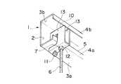
図21、22はこの横架材(例えばリップ溝形鋼1)に吊りボルトの上端部を支持させるための従来の吊りボルト支持具の一例を示している。
リップ溝形鋼1は、図21、22に示すように、底面板2と、この底面板2の両側から直角に設けられた2つの側面板3a、3bと、各側面板3a、3bの先端から直角に内側に折曲げられた各折曲げ縁部4a、4bとで構成され、各折曲げ縁部4a、4bの先端間に開口部5が形成されている。
【0004】
図21、22に示す従来の吊りボルト支持具10は、締付けボルト11を螺着するためのネジ穴12a及び吊りボルト6の上端部を螺着するためのネジ穴12bを備えた底板12と、この底板12の両側から上側へ直角に折曲げられ、リップ溝形鋼1の下側の折曲げ縁部4aを横方向の開口13aから上方へ挿入するための挿入溝13bを備えた2つの側板13、13とで構成されている。
【0005】
従って、この従来の吊りボルト支持具10を用いて吊りボルト6を支持させるには、2つの側板13、13の開口13a、13aから挿入溝13b、13b内へリップ溝形鋼1の下側の折曲げ縁部4aを挿入し、ネジ穴12aに螺着した締付けボルト11をネジ込んで締付けボルト11の先端11aと2つの側板13の各当接部13c、13cの下端との間でリップ溝形鋼1の下側の側面板3aを強く挟持することによって吊りボルト支持具10をリップ溝形鋼1に固定し、上端近傍にナット7を螺着した吊りボルト6を吊りボルト支持具10の底板12のネジ穴12bに螺着しさらにネジ込んで吊りボルト6の上端部を上方へ進出させた後、吊りボルト6がぐらつかないように底板12の下側からナット7を締付けていた。
【0006】
また、図23はリップ溝形鋼1に吊りボルト6の上端部を支持させるための従来の他の例の吊りボルト支持具20を示している。
【0007】
この吊りボルト支持具20は、先端に挟持片21が折り返された支持板22と、吊りボルト6の上端が取付けられるほぼ三角形状に折曲げられた取付け部23とで構成されている。
【0008】
挟持片21はバネ性を有し、下端部21aは支持板22から離れる方向に開いている。
取付け部23は、吊りボルト6の上端を螺着するためのネジ穴24aを備えた底板24と、この底板24の一端から垂直に折曲げられた垂直板25と、底板24の他端から垂直板25側へ斜め方向に折曲げられ長穴26aを備えた傾斜板26と、この傾斜板26の上端から垂直板25と平行な方向に延設された重ね板27とから成り、垂直板25と重ね板27が重ね合わせた状態で支持板22の下部に取付けられている。
【0009】
従って、この従来の吊りボルト支持具20を用いて吊りボルト6の上端部を支持させるには、リップ溝形鋼1の下側の折曲げ縁部4aの上端を支持板22の上部と挟持片21の下端部21aの間に位置させ、支持板22の上端をハンマーなどで下方へ打撃して支持板22の上端部と挟持片21の間に折曲げ縁部4aの上端部を叩き込んで固定し、上端近傍にナット28を螺着した吊りボルト6を吊りボルト支持具20の底板24のネジ穴24aに螺着し、さらにネジ込んで吊りボルト6の上端部を長穴26aの上方へ進出させた後、吊りボルト6がぐらつかないように底板24の下側からナット28を締付けていた。
【0010】
しかしながら、このような従来方法では、いずれも高所にある横架材(リップ溝形鋼1)の高さで脚立などを用いて吊りボルト支持具10、20や吊りボルト6の固定作業を行なわなければならないため、非常に危険であった。
【0011】
また、図21、22の吊りボルト支持具10では、締付けボルト11の締付け、吊りボルト6のネジ穴12bへの螺着、ナット7の締付けの3つの作業が必要なため、非常に煩雑で作業性が悪く多大な時間がかかっていた。
【0012】
また、図23の吊りボルト支持具20では、ハンマーなどによる叩き込み、吊りボルト6のネジ穴24aへの螺着、ナット28の締付けの3つの作業が必要なため、非常に煩雑で作業性が悪く多大な時間がかかっていた。また、ハンマーなどによる叩き込みはリップ溝形鋼1の上下の折曲げ縁部4b、4a間の狭い開口部5内で行なわなければならないため、非常にやりにくかった。
【0013】
本発明はこのような問題を解決し、高所作業を不要にし、且つ作業性を良くした吊りボルト支持具を提供することを目的としている。
【0014】
【課題を解決するための手段】
前記目的を達成するために、本発明の請求項1の吊りボルト支持具は、
ネジ穴が設けられた平板と、前記平板の両側から下方へ延設された一対の脚板と、前記脚板から横方向に延設された受け部とを備えた下部金具と、
上板と、前記上板の両側から下方へ延設され、前記受け部側の下端に挟持部を有する一対の側板とを備えた上部金具とから成り、
前記下部金具の上部に外側から前記上部金具を被せた状態で、前記下部金具の前記一対の脚板の上部で且つ前記平板のネジ穴より前記受け部側の位置において前記下部金具の前記一対の脚板と前記上部金具の前記一対の側板とが回動自在に連結されていて、
前記下部金具の前記ネジ穴に下側から吊りボルトの上端部を螺着して上方へ進出させ、吊りボルトの上端で前記上部金具の上板部の下面を押圧することによって前記上部金具の前記挟持部を前記下部金具の前記受け部に接近する方向に回動させることによって、前記上部金具の前記挟持部と前記下部金具の前記受け部とで横架材の板部を挟持させるようにしている。
【0015】
このように構成したため、前記下部金具の前記ネジ穴に下側から吊りボルトの上端部を螺着して上方へ僅かに進出させた状態で作業者が吊りボルトの下部を手に持って、上方の横架材の板部を前記下部金具の受け部と前記上部金具の挟持部の間に挿入し、手に持った吊りボルトを捻じって前記ネジ穴に螺着された上端部をさらに上方へ進出させ、これによって前記上部金具の上板を吊りボルトの上端で押圧して前記上部金具を回動させて、前記受け部と挟持部とで横架材の板部を挟持させればよいから、横架材のはるか下方からの操作で横架材に吊りボルトの上端部を支持させることができる。
【0016】
また、本発明の請求項2の吊りボルト支持具は、
ネジ穴が設けられた平板と、前記平板の両側から下方へ延設された一対の脚板と、前記脚板から横方向に延設された受け部とを備えた下部金具と、
上板と、前記上板の両側から下方へ延設され、前記受け部側の下端に挟持部を有し、且つ、前記挟持部より中央寄りに下端から上方へ設けられた切欠きを有する一対の側板とを備えた上部金具とから成り、
前記下部金具の上部に外側から前記上部金具を被せた状態で、前記下部金具の前記一対の脚板の上部で且つ前記平板のネジ穴より前記受け部側の位置において前記下部金具の前記一対の脚板と前記上部金具の前記一対の側板とが回動自在に連結されていて、
前記下部金具の前記ネジ穴に下側から吊りボルトの上端部を螺着して上方へ進出させ、吊りボルトの上端で前記上部金具の上板部の下面を押圧することによって前記上部金具の前記挟持部を前記下部金具の前記受け部に接近する方向に回動させることによって、前記上部金具の前記切欠きに横架材の折曲げ縁部を進入させると共に、前記上部金具の前記挟持部と前記下部金具の前記受け部とで横架材の板部を挟持させるようにしている。
【0017】
このように構成したため、前記下部金具の前記ネジ穴に下側から吊りボルトの上端部を螺着して上方へ僅かに進出させた状態で作業者が吊りボルトの下部を手に持って、上方の横架材の板部を前記下部金具の受け部と前記上部金具の挟持部の間に挿入し、手に持った吊りボルトを捻じって前記ネジ穴に螺着された上端部をさらに上方へ進出させ、これによって前記上部金具の上板を吊りボルトの上端で押圧して前記上部金具を回動させて、横架材の折曲げ縁部を前記上部金具の切欠きに進入させると共に、前記受け部と挟持部とで横架材の板部を挟持させればよいから、横架材のはるか下方からの操作で横架材に吊りボルトの上端部を支持させることができる。
【0018】
また、本発明の請求項3の吊りボルト支持具は、
上板と、前記上板の両側から下方へ延設された一対の脚板と、前記脚板から横方向へ延設された受け部とを備えた外部金具と、
ネジ穴が設けられた平板と、前記平板の両側から下方へ延設され、前記受け部側の下端に挟持部を有する一対の側板とを備えた内部金具とから成り、
前記内部金具に外側から前記外部金具を被せた状態で、前記内部金具の前記ネジ穴に下側から吊りボルトの上端部を螺着して上方へ進出させ、吊りボルトの上端で前記外部金具の上板の下面を押圧することによって前記内部金具を前記外部金具に対して下降させることによって、前記内部金具の前記挟持部と前記外部金具の前記受け部とで横架材の板部を挟持させるようにしている。
【0019】
このように構成したため、前記内部金具の前記ネジ穴に下側から吊りボルトの上端部を螺着して上方へ僅かに進出させた状態で作業者が吊りボルトの下部を手に持って、上方の横架材の板部を前記外部金具の受け部と前記内部金具の挟持部の間に挿入し、手に持った吊りボルトを捻じって前記ネジ穴に螺着された上端部をさらに上方へ進出させ、これによって前記外部金具の上板を吊りボルトの上端で押圧することによって前記内部金具を下降させて、前記受け部と挟持部とで横架材の板部を挟持させればよいから、横架材のはるか下方からの操作で横架材に吊りボルトの上端部を支持させることができる。
【0020】
また、本発明の請求項4の吊りボルト支持具は、
上板と、前記上板の両側から下方へ延設された一対の脚板と、前記脚板から横方向へ延設された受け部とを備えた外部金具と、
ネジ穴が設けられた平板と、前記平板の両側から下方へ延設され、前記受け部側の下端に挟持部を有し、且つ、前記挟持部より中央寄りに下端から上方へ設けられた切欠きを有する一対の側板とを備えた内部金具とから成り、
前記内部金具に外側から前記外部金具を被せた状態で、前記内部金具の前記ネジ穴に下側から吊りボルトの上端部を螺着して上方へ進出させ、吊りボルトの上端で前記外部金具の上板の下面を押圧することによって前記内部金具を前記外部金具に対して下降させることによって、前記内部金具の前記切欠きに横架材の折曲げ縁部を進入させると共に、前記内部金具の前記挟持部と前記外部金具の前記受け部とで横架材の板部を挟持させるようにしている。
【0021】
このように構成したため、前記内部金具の前記ネジ穴に下側から吊りボルトの上端部を螺着して上方へ僅かに進出させた状態で作業者が吊りボルトの下部を手に持って、上方の横架材の板部を前記外部金具の受け部と前記内部金具の挟持部の間に挿入し、手に持った吊りボルトを捻じって前記ネジ穴に螺着された上端部をさらに上方へ進出させ、これによって前記外部金具の上板を吊りボルトの上端で押圧することによって前記内部金具を下降させて、横架材の折曲げ縁部を前記内部金具の切欠きに進入させると共に、前記受け部と挟持部とで横架材の板部を挟持させればよいから、横架材のはるか下方からの操作で横架材に吊りボルトの上端部を支持させることができる。
【0024】
【発明の実施の形態】
以下、図面に基づいて本発明の実施の形態を説明する。
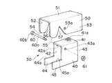
図1〜6は本発明の吊りボルト支持具の一実施形態を示している。
【0025】
この吊りボルト支持具30は、下部金具40と上部金具50によって構成されている。
下部金具40は、平板41と、この平板41の両側から下方へほぼ垂直方向に延設された互いに平行な一対の脚板42、43を備えている。
【0026】
一対の脚板42、43には、前記平板41の近傍で且つ横方向の一端側において、上部金具50を連結するための軸穴(連結部)42a、43aがそれぞれに設けられている。
【0027】
前記脚板42、43の横方向の一端側(軸穴42a、43a側)において、且つ、脚板42、43の下端部において、横架材の板部の下面を上端面44a、45aで受けるための一対の互いに平行な平板状の受け部44、45がそれぞれ横方向に延設されている。
前記平板41には、脚板42、43の前記軸穴42a、43aに関して前記受け部44、45と反対側の位置に、吊りボルト6の上端部を螺着するためのネジ穴41aが設けられている。
【0028】
上部金具50は、上板51と、この上板51の両側から下方に前記下部金具40の一対の脚板42、43の外側に位置するようにほぼ垂直方向に延設された互いに平行な一対の側板52、53とを備えている。この側板52、53の下端寄りで且つ横方向の中間部において、下部金具40を連結するための軸穴(連結部)52a、53aが設けられている。
【0029】
そして、下部金具40の上部に外側から上部金具50を被せた状態で、上部金具50及び下部金具40の前記軸穴52a、53a、42a、43aに、ボルト60の軸60aが挿通され、軸60aの先端にナット61が螺着されていて、ボルト60の頭部60bとナット61とで上部金具50の側板52、53の横方向の動きが規制されている。このようにして下部金具40に上部金具50が軸60aを中心に回動自在に連結されている。
【0030】
上部金具50の側板52、53の上下方向の高さは、上部金具50が水平状態の場合に、側板52、53の下部金具40の受け部44、45側の端部の下端の挟持部54、55と下部金具40の受け部44、45の上端面44a、45aとの間隔が横架材の挟持されるべき板部(前記リップ溝形鋼1の側板3aあるいは図3、4に示すL形鋼7の水平板7a)の厚さより大となるように設定されている。
【0031】
前記挟持部54、55は、図4、図6に示すように上部金具50が反時計回りに回動した状態で横架材の板部(リップ溝形鋼1の側板3aあるいはL形鋼7の水平板7a)の上面に接触しやすいように、また、リップ溝形鋼1の側板3aあるいはL形鋼7の水平板7aを下部金具40の受け部44、45の上端面44a、45aとの間に挿入しやすいように、テーパー状にすることが望ましい。
【0032】
また、上部金具50の側板52、53には、前記挟持部54、55と軸穴52a、53aとの間において、前記リップ溝形鋼1の下側の折曲げ縁部4aを受け入れるための切欠き56、57が設けられている。この切欠き56、57の入口側(下側)は上部金具50の回動時に前記折曲げ縁部4aに衝突しないように下側が次第に広がった形状となっている。
【0033】
なお、上部金具50の前記軸穴52a、53aの位置を上部金具50の重心位置より挟持部54、55寄りにすれば、上部金具50を下部金具40に連結した状態で、図3、図5に示すように上部金具50が自重で時計回りに回動して挟持部54、55と受け部44、45の上端面44a、45aとの間隔が開くから、リップ溝形鋼1の側板3aあるいはL形鋼7の水平板7aを挟持部54、55と受け部44、45の上端面44a、45aとの間隔に挿入しやすくなる。
【0034】
次に、この吊りボルト支持具30の使用法を説明する。
まず、図3あるいは図5に示すように、吊りボルト6をその上端6aが下部金具40の平板41のネジ穴41aから上方へ僅かに突出した状態に螺着する。
【0035】
そして、吊りボルト6の下端部を作業者が手で持って、吊りボルト6の上端部の吊りボルト支持具30を上方の横架材、例えば図3に示すようにL形鋼7の高さまで差し上げた後、吊りボルト支持具30を左方へ動かして、横架材の板部(L形鋼7の水平板7a)を、下部金具40の受け部44、45の上端面44a、45aと上部金具50の挟持部54、55の間に奥まで挿入する。
【0036】
そして、この状態で吊りボルト6を下方から手であるいは電動回転工具などを用いて回転させて、図4に示すように吊りボルト6の上端6aを前記ネジ穴41aにおいてさらに上方へ進出させる。これによって上部金具50の上板51を吊りボルト6の上端6aで押圧して、上部金具50を軸60aを中心に反時計回りに回動させて、受け部44、45の上端部44a,45aと挟持部54、55とで横架材の板部(L形鋼7の水平板7a)を強く挟持させることにより、水平板7aに吊りボルト支持具30及び吊りボルト6がしっかりと固定できる。
【0037】
このように、横架材(L形鋼7)のはるか下方からの操作で横架材(L形鋼7)に吊りボルト6の上部を支持させることができる。
【0038】
なお、図5、6に示すように、横架材がリップ溝形鋼1である場合には、吊りボルト6の下端部を作業者が手で持って、上端の吊りボルト支持具30の上部金具50の左端側をリップ溝形鋼1の開口部5に入れるようにして、下側の折曲げ縁部4aを下部金具40の受け部44、45の上端面44a、45aと上部金具50の挟持部54、55の間に奥まで挿入させる。
【0039】
そして、吊りボルト6を下方から手であるいは電動回転工具などを用いて回転させて吊りボルト6の上端6aを前記ネジ穴41aにおいてさらに上方へ進出させ、これによって上部金具50の上板51を吊りボルト6の上端6aで押圧して上部金具50を軸60aを中心に反時計回りに回動させて、折曲げ縁部4aを上部金具50の側板52、53の切欠き56、57内に進入させると共に、受け部44、45の上端部44a,45aと挟持部54、55とで横架材の板部(リップ溝形鋼1の下側の側板3a)を挟持させる。
【0040】
このようにして、横架材(リップ溝形鋼1)のはるか下方からの操作で吊りボルト6の上部を横架材(リップ溝形鋼1)に支持させることができる。
【0041】
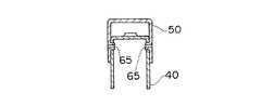
なお、図1、2に示した実施形態では、上部金具50及び下部金具40の軸穴52a、53a、42a、43aに、ボルト60の軸60aを挿通して回動自在に連結した場合を例示したが、上部金具50の側板52、53に、軸穴52a、53aの代りに、図7に示すバーリング加工による内方へ突出した円筒状の突起65、65を設けて、下部金具40の軸穴42a、43aにこの突起65、65を外側から挿入して下部金具40と上部金具50を回動自在に連結してもよい。
【0042】
また、図8に示すエンボス加工による内方へ突出した半球状の突起66、66を設けて、下部金具40の軸穴42a、43aにこの突起66、66を外側から挿入して下部金具40と上部金具50を回動自在に連結してもよい。
【0043】
また、図9に示す切起こし加工による内方へ突出した板状の突起67、67を設けて、下部金具40の軸穴42a、43aにこの突起67、67を外側から挿入して下部金具40と上部金具50を回動自在に連結してもよい。
【0044】
なお、図7、図8、図9とは逆に、下部金具40の方に軸穴42a、43aの代りに外方へ突出した突起(図示せず)を設けて、上部金具50の軸穴52a、53aに下部金具40に設けた突起を内側から挿入して下部金具40と上部金具50を回動自在に連結してもよい。
【0045】
なお、この吊りボルト支持具30を、リップ溝形鋼1には用いず、L形鋼7のように折曲げ縁部のないものにのみ用いる場合には、上部金具50の前記切欠き56、57を設けなくてもよい。
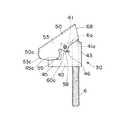
【0046】
図10〜12は本発明の他の実施形態を示している。
この実施形態の吊りボルト支持具30では、上部金具50の左端側50aが下部金具40の左端の受け部44、45よりさらに左方へ突出して設けられ、また、上部金具50の右端側は図12に示すように横架材に取付けた状態で下部金具40の脚板42、43より右方へ突出しないように短く、且つ、側板52、53の右端側は下方が狭くなるように斜めに傾斜した傾斜辺68となっている。
【0047】
このため、上部金具50の重心は側板52、53の回転中心(軸60a)より左側に位置することになるため、側板53には、軸穴53aの下方において係止部58を設け、下部金具40の脚板43に例えば切起こしによるストッパー用突起46を設けて、上部金具50の自重による反時計回りの回動は、このストッパー用突起46に係止部58が係止することによって阻止され、このため、挟持部54、55が受け部44、45の上端面44a、45aより僅かに上方かあるいは僅かに下方に位置している。
【0048】
このため、図10の状態で吊りボルト6の端部を作業者が手で持って、吊りボルト6の上端部の吊りボルト支持具30を、L形鋼7の水平板7aの先端あるいは図11に示すようにリップ溝形鋼1の折曲げ縁部4aの上端面に上部金具50の左下隅部52c、53cを引っ掛けて、上部金具50を軸60aを中心に時計回りに回動させて、上部金具50の挟持部54、55と下部金具40の受け部44、45の上端面44a、45aの間を開き、L形鋼7の水平部7aあるいはリップ溝形鋼1の折曲げ縁部4aを奥まで挿入する。そして、以下、前記と同様に吊りボルト6を下方で回転させて、図12に示すように上部金具50を反時計回りに回動させることによって受け部44、45の上端部44a、45aと挟持部54、55とで水平板7aあるいは側板3aを挟持させる。
【0049】
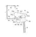
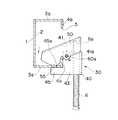
図13は本発明の他の実施形態の吊りボルト支持具70を示している。
この吊りボルト支持具70は外部金具80と内部金具90とによって構成されている。
【0050】
外部金具80は、平板81と、この平板81の両側から下方へほぼ垂直方向に延設された互いに平行な一対の脚板82、83を備えている。
【0051】
前記脚板82、83の横方向の一端側において、且つ、脚板82、83の下端部において、横架材の板部の下面を上端面84a、85aで受けるための一対の互いに平行な平板状の受け部84、85がそれぞれ横方向に延設されている。
【0052】
内部金具90は、外部金具80の一対の脚板82、83の間の距離より小さい幅の平板91と、この平板91の両側から下方に前記外部金具80の一対の脚板82、83の内側に位置するようにほぼ垂直方向に延設された一対の側板92、93とを備えている。
【0053】
側板92、93の右端には、外方に向かってほぼ垂直方向に延設され、外部金具80の脚板82、83の横方向の外側の端面86に接触して右方へ外れないように係止し、且つ脚板82、83の前記端面86に沿って内部金具90が上下動するガイドのためのガイド片94、95が設けられている。
【0054】
また、側板92、93の左側の下端部には挟持部96、97が設けられ、この挟持部96、97よりガイド片94、95側には、下方から切欠き98、99が設けられている。
内部金具90の平板91のガイド片94、95側の端部には、吊りボルト6の上端部を下方から螺着するためのネジ穴91aが設けられている。
【0055】
次に、この実施形態の吊りボルト支持具70の使用方法を説明する。
まず、図14に示すように、吊りボルト6をその上端6aが内部金具90の平板91のネジ穴91aから上方へ僅かに突出した状態に螺着し、吊りボルト6の上端6aに外部金具80の上板81の下面が接触した状態にする。
【0056】
この状態において、内部金具90の挟持部96、97と外部金具80の受け部84、85の上端面84a、85aとの間に大きな間隔があいている。
【0057】
この状態で吊りボルト6の下端部を作業者が手で持って、吊りボルト6の上端部の吊りボルト支持具70を上方の横架材(例えばL形鋼7あるいは図14に示すリップ溝形鋼1)の高さまで差し上げた後、吊りボルト支持具70を左方へ動かして、L形鋼7の水平板7aあるいは図15に示すリップ溝形鋼1の下側の折曲げ縁部4aを外部金具80の受け部84、85の上端面84a、85aと挟持部96、97の間に奥まで挿入する。
【0058】
そして、この状態で吊りボルト6を下方で手であるいは電動回転工具などを用いて回転させて、吊りボルト6の上端6aを前記ネジ穴91aにおいてさらに上方へ進出させる。吊りボルト6の上端6aは前記したように外部金具80の上板81の下面に接触しているので、吊りボルト6の回転によって吊りボルト6の上端6aの平板91から上方への進出量が増加する量だけ、内部金具90は外部金具80に対して下降し、この結果、L形鋼7の場合にはその水平板7aが外部金具80の受け部84、85の上端面84a、85aと挟持部96、97とで挟持され、図15に示すようにリップ溝形鋼1の場合には、その下側の折曲げ縁部4aが内部金具90の前記切欠き98、99に進入すると共に、下側の側板3aが外部金具80の受け部84、85の上端面84a、85aと挟持部96、97とで挟持される。
【0059】
このようにして、横架材のはるか下方において吊りボルト6の上部を横架材に支持させることができる。
【0060】
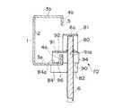
図16〜20はさらに本発明の他の実施形態を示している。
【0061】
この実施形態の吊りボルト支持具100は、帯板状の金属板をほぼコ字状に屈曲したものであって、ネジ穴101aが設けられた平板101の一端から上方へ垂直方向に垂直板102が延設されている。この垂直板102の上下方向の長さは、図20に示すように、開口部5を横向きにした状態でのリップ溝形鋼1の底板2の上下方向の幅より充分に大に設定されている。
【0062】
前記垂直板102の上端から前記水平板101と同じ側に水平方向に押さえ板103が延設され、この押さえ板103の先端から下方へ垂直方向に係止片104が延設されている。
【0063】
また、前記平板101の他端からは、上方へ垂直方向に前記係止片104と対向して掛止め板105が延設されていて、この掛止め板105の上端には内方へ下向きに屈曲された掛止め片105aが設けられている。
【0064】
前記押さえ板103の水平方向の長さ(即ち、垂直板102と係止片104間の距離)及び前記平板101の水平方向の長さ(即ち、垂直板102と掛止め板105間の距離)は、図20に示すように、開口部5を横向きにした状態でのリップ溝形鋼1の側板3b及び側板3aの水平方向の長さより僅かに大に設定されている。
【0065】
次に、この吊りボルト支持具100の使用方法を説明する。
まず、吊りボルト6をその上端6aが平板101のネジ穴101aから上方へ僅かに突出した状態に螺着する。
【0066】
この状態で吊りボルト6の下端部を作業者が手に持って、図17に示すように、吊りボルト6の上端部の吊りボルト支持具100を上方の横架材(リップ溝形鋼1)の高さまで斜め方向に差し上げた後、吊りボルト支持具100の係止部104と掛止め片105aの間にリップ溝形鋼1下部を奥まで挿入する。
【0067】
そして、掛止め片105aの下側に折曲げ縁部4aをいれ、掛止め片105aの下側で掛止め板105の内側に折曲げ縁部4aを押し付けるようにして、図18に示すように、吊りボルト6及び吊りボルト支持具100を時計回りに回転させるように吊りボルト6の下端を左方向に移動させて、リップ溝形鋼1の底板2を垂直板102が外側から覆い、側板3bを押さえ板103が上側から覆うように被せて、図19に示すようにリップ溝形鋼1の底板2が吊りボルト支持具100の垂直板102の内面に密着し、吊りボルト支持具100の係止部104の内面がリップ溝形鋼1の上側の折曲げ縁部4bの外面に接触し、掛止め板105の内面が下側の折曲げ縁部4aの外面に接触した状態にする。
【0068】
そして、この状態で吊りボルト6を下方で手であるいは電動回転工具などを用いて回転させて、吊りボルト6の上端6aを前記ネジ穴101aにおいてさらに上方へ進出させる。これによって吊りボルト6の上端6aがリップ溝形鋼1の下側の側板3aに接触し、さらに吊りボルト6の上端6aがネジ穴101aより上方へ進出するにつれて、吊りボルト6の上端6aと吊りボルト支持具100の押さえ板103との距離が次第に小になるので、図20に示すように押さえ板103がリップ溝形鋼1の上側の側板3bに押圧されると共に、下側の側板3aに吊りボルト6の上端6aが押圧され挟持される。そして、係止部104が上側の折曲げ縁部4bに外側から脱落不能なように係止し、且つ掛止め板105が下側の折曲げ縁部4aに外側から接触し、且つ掛止め片105aが折曲げ縁部4aの上端に係止した状態となる。
【0069】
このようにして、横架材のはるか下方において吊りボルト6の上部を横架材に支持させることができる。
【0070】
このように、吊りボルト6の上端6aと前記押さえ板103とで挟持することによって固定する構造であるから、前記掛止め板105及び掛止め片105aを省略してもよく、あるいは前記係止片104を省略してもよい。
【0071】
なお、掛止め板105及び係止部104を設ければ、掛止め板105及び係止部104がそれぞれ下側の折曲げ縁部4a及び上側の折曲げ縁部4bに係止しているため、吊りボルト6の回転によって吊りボルト支持具100がリップ溝形鋼1に対して回転しようとするのを防ぐことができ、また、脱落を確実に防ぐことができる。
【0072】
【発明の効果】
以上説明したように、本発明の吊りボルト支持具は構成されているので、高所にある横架材の高さで直接ボルト締めなどをする必要がなく、横架材のはるか下方で作業できるから、脚立の上に立って作業する必要がなく、高所作業の危険を解消することができる。
【図面の簡単な説明】
【図1】本発明の一実施形態を示す分解斜視図
【図2】同実施形態の断面図
【図3】同実施形態の使用状態を示す断面図
【図4】同実施形態の使用状態を示す断面図
【図5】同実施形態の使用状態を示す断面図
【図6】同実施形態の使用状態を示す断面図
【図7】本発明の他の実施形態を示す断面図
【図8】本発明の他の実施形態を示す断面図
【図9】本発明の他の実施形態を示す断面図
【図10】本発明のさらに他の実施形態を示す正面図
【図11】同実施形態の使用状態を示す正面図
【図12】同実施形態の使用状態を示す正面図
【図13】本発明のさらに他の実施形態を示す分解斜視図
【図14】同実施形態の使用状態を示す断面図
【図15】同実施形態の使用状態を示す断面図
【図16】本発明のさらに他の実施形態を示す斜視図
【図17】同実施形態の使用状態を示す断面図
【図18】同実施形態の使用状態を示す断面図
【図19】同実施形態の使用状態を示す断面図
【図20】同実施形態の使用状態を示す断面図
【図21】従来の吊りボルト支持具の使用状態を示す斜視図
【図22】図21の従来の吊りボルト支持具の使用状態を示す断面図
【図23】従来の他の吊りボルト支持具の使用状態を示す断面図
【符号の説明】
1 リップ溝形鋼
3a 側面板
4a 折曲げ縁部
5 開口部
6 吊りボルト
6a 上端
7 L形鋼
7a 水平板
30 吊りボルト支持具
40 下部金具
41 平板
41a ネジ穴
44、45 受け部
50 上部金具
51 上板
54、55 挟持部
56、57 切欠き
70 吊りボルト支持具
80 外部金具
81 上板
84、85 受け部
90 内部金具
91 平板
91 ネジ穴
94、95 ガイド片
96、97 挟持部
98、99 切欠き
100 吊りボルト支持具
101 水平板
101a ネジ穴
102 垂直板
103 押さえ板
104 係止板
105 掛止め板
105a 掛止め片[0001]
BACKGROUND OF THE INVENTION
The present invention relates to a support for supporting a suspension bolt on a horizontal member.
[0002]
[Prior art and problems to be solved]
In buildings, factories, warehouses, station buildings, and other various structures, horizontal members (such as lip groove steel and L-shaped steel) are installed horizontally above the ceiling and other lighting fixtures. It is common practice to suspend and support various other devices using suspension bolts.
[0003]
21 and 22 show an example of a conventional suspension bolt support for supporting the upper end portion of the suspension bolt on the horizontal member (for example, the lip groove steel 1).
As shown in FIGS. 21 and 22, the lip groove steel 1 includes a
[0004]
The conventional
[0005]
Therefore, in order to support the
[0006]
FIG. 23 shows another conventional
[0007]
The
[0008]
The
The
[0009]
Therefore, in order to support the upper end portion of the
[0010]
However, in such conventional methods, the suspension bolts 10 and 20 and the
[0011]
21 and 22 requires three operations of tightening the tightening
[0012]
In addition, the
[0013]
An object of the present invention is to provide a suspension bolt support that solves such problems, eliminates the need for work at a high place, and improves workability.
[0014]
[Means for Solving the Problems]
In order to achieve the above object, the suspension bolt support according to claim 1 of the present invention comprises:
A lower fitting including a flat plate provided with screw holes, a pair of leg plates extending downward from both sides of the flat plate, and a receiving portion extending laterally from the leg plate;
The upper plate comprises an upper metal fitting provided with a pair of side plates extending downward from both sides of the upper plate and having a sandwiching portion at the lower end on the receiving portion side,
The pair of leg plates of the lower metal fitting at a position above the pair of leg plates of the lower metal fitting and on the side of the receiving part from the screw hole of the flat plate with the upper metal fitting covered from the outside on the upper part of the lower metal fitting. And the pair of side plates of the upper metal fitting are rotatably connected,
The upper end of the suspension bolt is screwed into the screw hole of the lower bracket from below and advanced upward, and the upper surface of the upper bracket is pressed against the lower surface of the upper bracket by the upper end of the suspension bolt. By rotating the holding portion in a direction approaching the receiving portion of the lower metal fitting, the plate portion of the horizontal member is held between the holding portion of the upper metal fitting and the receiving portion of the lower metal fitting. Yes.
[0015]
With this configuration, the operator holds the lower end of the suspension bolt in his hand while the upper end of the suspension bolt is screwed into the screw hole of the lower bracket from the lower side and slightly advanced upward. The plate portion of the horizontal member is inserted between the receiving portion of the lower metal fitting and the holding portion of the upper metal fitting, and the upper end portion screwed into the screw hole by twisting the holding bolt held by the hand is further upward Then, the upper plate of the upper bracket is pressed by the upper end of the suspension bolt to rotate the upper bracket, and the plate portion of the horizontal member may be clamped between the receiving portion and the clamping portion. Thus, the upper end of the suspension bolt can be supported on the horizontal member by an operation from a far lower side of the horizontal member.
[0016]
The suspension bolt support of
A lower fitting including a flat plate provided with screw holes, a pair of leg plates extending downward from both sides of the flat plate, and a receiving portion extending laterally from the leg plate;
A pair having an upper plate and a lower portion extending from both sides of the upper plate, having a holding portion at the lower end on the receiving portion side, and having a notch provided upward from the lower end closer to the center than the holding portion. And the upper bracket with the side plate,
The pair of leg plates of the lower metal fitting at a position above the pair of leg plates of the lower metal fitting and on the side of the receiving part from the screw hole of the flat plate with the upper metal fitting covered from the outside on the upper part of the lower metal fitting. And the pair of side plates of the upper metal fitting are rotatably connected,
The upper end of the suspension bolt is screwed into the screw hole of the lower bracket from below and advanced upward, and the upper surface of the upper bracket is pressed against the lower surface of the upper bracket by the upper end of the suspension bolt. By turning the holding part in a direction approaching the receiving part of the lower metal part, the bent edge of the horizontal member is entered into the notch of the upper metal part, and the holding part of the upper metal part is The plate portion of the horizontal member is sandwiched between the receiving portion of the lower metal fitting.
[0017]
With this configuration, the operator holds the lower end of the suspension bolt in his hand while the upper end of the suspension bolt is screwed into the screw hole of the lower bracket from the lower side and slightly advanced upward. The plate portion of the horizontal member is inserted between the receiving portion of the lower metal fitting and the holding portion of the upper metal fitting, and the upper end portion screwed into the screw hole by twisting the holding bolt held by the hand is further upward As a result, the upper plate of the upper metal fitting is pushed by the upper end of the suspension bolt to rotate the upper metal fitting, and the bent edge of the horizontal member is entered into the notch of the upper metal fitting, Since the plate portion of the horizontal member only needs to be held between the receiving portion and the holding portion, the upper end portion of the suspension bolt can be supported on the horizontal member by an operation from a far lower side of the horizontal member.
[0018]
Moreover, the suspension bolt support of Claim 3 of this invention is
An external fitting comprising an upper plate, a pair of leg plates extending downward from both sides of the upper plate, and a receiving portion extending laterally from the leg plate;
It consists of a flat plate provided with screw holes, and an internal metal fitting provided with a pair of side plates extending downward from both sides of the flat plate and having a clamping part at the lower end on the receiving part side,
With the inner metal fitting being covered from the outside to the inner metal fitting, the upper end portion of the suspension bolt is screwed into the screw hole of the inner metal fitting from the lower side to advance upward, and the upper end of the outer metal fitting is By pressing the lower surface of the upper plate, the inner metal member is lowered with respect to the outer metal member, so that the plate portion of the horizontal member is held between the holding portion of the inner metal member and the receiving portion of the outer metal member. I am doing so.
[0019]
With this configuration, the operator holds the lower part of the suspension bolt in his hand while the upper end of the suspension bolt is screwed into the screw hole of the inner metal fitting from below and slightly lifted upward. The plate part of the horizontal member is inserted between the receiving part of the external metal fitting and the holding part of the internal metal fitting, and the upper end part screwed into the screw hole by twisting the holding bolt held by the hand is further upward The upper metal plate is pushed down by the upper end of the suspension bolt, thereby lowering the inner metal fitting and sandwiching the plate portion of the horizontal member between the receiving portion and the holding portion. Thus, the upper end of the suspension bolt can be supported on the horizontal member by an operation from a far lower side of the horizontal member.
[0020]
In addition, the suspension bolt support of claim 4 of the present invention is
An external fitting comprising an upper plate, a pair of leg plates extending downward from both sides of the upper plate, and a receiving portion extending laterally from the leg plate;
A flat plate provided with screw holes, a cut extending from both sides of the flat plate, having a holding portion at the lower end on the receiving portion side, and provided from the lower end to the upper side closer to the center than the holding portion Consisting of an internal metal fitting with a pair of side plates having notches,
With the inner metal fitting being covered from the outside to the inner metal fitting, the upper end portion of the suspension bolt is screwed into the screw hole of the inner metal fitting from the lower side to advance upward, and the upper end of the outer metal fitting is The inner metal fitting is lowered with respect to the outer metal fitting by pressing the lower surface of the upper plate, thereby causing the bent edge of the horizontal member to enter the notch of the inner metal fitting, and the inner metal fitting The plate portion of the horizontal member is held between the holding portion and the receiving portion of the external metal fitting.
[0021]
With this configuration, the operator holds the lower part of the suspension bolt in his hand while the upper end of the suspension bolt is screwed into the screw hole of the inner metal fitting from below and slightly lifted upward. The plate part of the horizontal member is inserted between the receiving part of the external metal fitting and the holding part of the internal metal fitting, and the upper end part screwed into the screw hole by twisting the holding bolt held by the hand is further upward And lowering the internal metal fitting by pressing the upper plate of the external metal fitting with the upper end of the suspension bolt, thereby causing the bent edge of the horizontal member to enter the notch of the internal metal fitting, Since the plate portion of the horizontal member only needs to be held between the receiving portion and the holding portion, the upper end portion of the suspension bolt can be supported on the horizontal member by an operation from a far lower side of the horizontal member.
[0024]
DETAILED DESCRIPTION OF THE INVENTION
Hereinafter, embodiments of the present invention will be described with reference to the drawings.
1-6 has shown one Embodiment of the suspension bolt support of this invention.
[0025]
The
The
[0026]
The pair of
[0027]
For receiving the lower surface of the plate portion of the horizontal member at the upper end surfaces 44a and 45a at one end side (the shaft holes 42a and 43a side) of the
The
[0028]
The upper metal fitting 50 is a pair of parallel parallel to each other that extends in a substantially vertical direction so as to be positioned outside the pair of
[0029]
Then, the
[0030]
The height of the
[0031]
As shown in FIGS. 4 and 6, the sandwiching
[0032]
Further, the
[0033]
3 and 5 in a state where the upper metal fitting 50 is connected to the
[0034]
Next, how to use the
First, as shown in FIG. 3 or FIG. 5, the
[0035]
Then, the operator holds the lower end portion of the
[0036]
In this state, the
[0037]
Thus, the upper part of the
[0038]
As shown in FIGS. 5 and 6, when the horizontal member is the lip groove steel 1, the operator holds the lower end portion of the
[0039]
Then, the
[0040]
In this way, the upper part of the
[0041]
In the embodiment shown in FIGS. 1 and 2, the case where the
[0042]
Further,
[0043]
Further, plate-
[0044]
7, 8, and 9, a projection (not shown) protruding outward is provided on the
[0045]
In addition, when this suspension
[0046]
10-12 show other embodiments of the present invention.
In the
[0047]
For this reason, the center of gravity of the upper metal fitting 50 is located on the left side of the center of rotation (
[0048]
For this reason, the operator holds the end of the
[0049]
FIG. 13 shows a
The
[0050]
The external metal fitting 80 includes a
[0051]
A pair of parallel plate-like plates for receiving the lower surface of the plate portion of the horizontal member at the
[0052]
The internal metal fitting 90 is positioned inside the pair of
[0053]
At the right ends of the
[0054]
Further, sandwiching
A
[0055]
Next, the usage method of the suspension
First, as shown in FIG. 14, the
[0056]
In this state, there is a large gap between the clamping
[0057]
In this state, the operator holds the lower end of the
[0058]
In this state, the
[0059]
In this way, the upper part of the
[0060]
16 to 20 show still another embodiment of the present invention.
[0061]
The
[0062]
A
[0063]
A latching
[0064]
The horizontal length of the pressing plate 103 (that is, the distance between the
[0065]
Next, the usage method of this suspension
First, the
[0066]
In this state, the operator holds the lower end portion of the
[0067]
Then, the
[0068]
Then, in this state, the
[0069]
In this way, the upper part of the
[0070]
Thus, since it is the structure fixed by pinching with the
[0071]
If the
[0072]
【The invention's effect】
As described above, since the suspension bolt support of the present invention is configured, it is not necessary to perform bolting directly at the height of the horizontal member at a high place, and the work can be performed far below the horizontal member. Therefore, it is not necessary to work while standing on a stepladder, and the danger of working at heights can be eliminated.
[Brief description of the drawings]
FIG. 1 is an exploded perspective view showing an embodiment of the present invention.
FIG. 2 is a sectional view of the same embodiment
FIG. 3 is a cross-sectional view showing a use state of the embodiment
FIG. 4 is a cross-sectional view showing a usage state of the embodiment
FIG. 5 is a sectional view showing a usage state of the embodiment;
FIG. 6 is a sectional view showing a usage state of the embodiment;
FIG. 7 is a sectional view showing another embodiment of the present invention.
FIG. 8 is a sectional view showing another embodiment of the present invention.
FIG. 9 is a sectional view showing another embodiment of the present invention.
FIG. 10 is a front view showing still another embodiment of the present invention.
FIG. 11 is a front view showing a usage state of the embodiment;
FIG. 12 is a front view showing a usage state of the embodiment;
FIG. 13 is an exploded perspective view showing still another embodiment of the present invention.
FIG. 14 is a sectional view showing a usage state of the embodiment;
FIG. 15 is a sectional view showing a usage state of the embodiment;
FIG. 16 is a perspective view showing still another embodiment of the present invention.
FIG. 17 is a sectional view showing the usage state of the embodiment;
FIG. 18 is a sectional view showing the usage state of the embodiment;
FIG. 19 is a sectional view showing the usage state of the embodiment;
FIG. 20 is a sectional view showing the usage state of the embodiment;
FIG. 21 is a perspective view showing a usage state of a conventional suspension bolt support tool.
22 is a sectional view showing a usage state of the conventional suspension bolt support of FIG.
FIG. 23 is a cross-sectional view showing a usage state of another conventional suspension bolt support
[Explanation of symbols]
1 Lip channel steel
3a Side plate
4a Bending edge
5 openings
6 Hanging bolt
6a top
7 L-shape steel
7a horizontal plate
30 Suspension bolt support
40 Lower bracket
41 flat plate
41a Screw hole
44, 45 Receiver
50 Upper bracket
51 Upper plate
54, 55 Nipping part
56, 57 Notch
70 Suspension bolt support
80 External bracket
81 Upper plate
84, 85 receptacle
90 Internal metal fittings
91 flat plate
91 Screw hole
94, 95 Guide piece
96, 97 clamping part
98, 99 Notch
100 Suspension bolt support
101 horizontal plate
101a Screw hole
102 Vertical plate
103 holding plate
104 Locking plate
105 Suspension plate
105a Latching piece
Claims (4)
Translated fromJapanese上板と、前記上板の両側から下方へ延設され、前記受け部側の下端に挟持部を有する一対の側板とを備えた上部金具とから成り、
前記下部金具の上部に外側から前記上部金具を被せた状態で、前記下部金具の前記一対の脚板の上部で且つ前記平板のネジ穴より前記受け部側の位置において前記下部金具の前記一対の脚板と前記上部金具の前記一対の側板とが回動自在に連結されていて、
前記下部金具の前記ネジ穴に下側から吊りボルトの上端部を螺着して上方へ進出させ、吊りボルトの上端で前記上部金具の上板部の下面を押圧することによって前記上部金具の前記挟持部を前記下部金具の前記受け部に接近する方向に回動させることによって、前記上部金具の前記挟持部と前記下部金具の前記受け部とで横架材の板部を挟持させるようにしたことを特徴とする吊りボルト支持具。A lower fitting including a flat plate provided with screw holes, a pair of leg plates extending downward from both sides of the flat plate, and a receiving portion extending laterally from the leg plate;
The upper plate comprises an upper metal fitting provided with a pair of side plates extending downward from both sides of the upper plate and having a sandwiching portion at the lower end on the receiving portion side,
The pair of leg plates of the lower metal fitting at a position above the pair of leg plates of the lower metal fitting and on the side of the receiving part from the screw hole of the flat plate with the upper metal fitting covered from the outside on the upper part of the lower metal fitting. And the pair of side plates of the upper metal fitting are rotatably connected,
The upper end of the suspension bolt is screwed into the screw hole of the lower bracket from below and advanced upward, and the upper surface of the upper bracket is pressed against the lower surface of the upper bracket by the upper end of the suspension bolt. By rotating the holding portion in a direction approaching the receiving portion of the lower metal fitting, the plate portion of the horizontal member is held between the holding portion of the upper metal fitting and the receiving portion of the lower metal fitting. A suspension bolt support characterized by that.
上板と、前記上板の両側から下方へ延設され、前記受け部側の下端に挟持部を有し、且つ、前記挟持部より中央寄りに下端から上方へ設けられた切欠きを有する一対の側板とを備えた上部金具とから成り、
前記下部金具の上部に外側から前記上部金具を被せた状態で、前記下部金具の前記一対の脚板の上部で且つ前記平板のネジ穴より前記受け部側の位置において前記下部金具の前記一対の脚板と前記上部金具の前記一対の側板とが回動自在に連結されていて、
前記下部金具の前記ネジ穴に下側から吊りボルトの上端部を螺着して上方へ進出させ、吊りボルトの上端で前記上部金具の上板部の下面を押圧することによって前記上部金具の前記挟持部を前記下部金具の前記受け部に接近する方向に回動させることによって、前記上部金具の前記切欠きに横架材の折曲げ縁部を進入させると共に、前記上部金具の前記挟持部と前記下部金具の前記受け部とで横架材の板部を挟持させるようにしたことを特徴とする吊りボルト支持具。A lower fitting including a flat plate provided with screw holes, a pair of leg plates extending downward from both sides of the flat plate, and a receiving portion extending laterally from the leg plate;
A pair having an upper plate and a lower portion extending from both sides of the upper plate, having a holding portion at the lower end on the receiving portion side, and having a notch provided upward from the lower end closer to the center than the holding portion. And the upper bracket with the side plate,
The pair of leg plates of the lower metal fitting at a position above the pair of leg plates of the lower metal fitting and on the side of the receiving part from the screw hole of the flat plate with the upper metal fitting covered from the outside on the upper part of the lower metal fitting. And the pair of side plates of the upper metal fitting are rotatably connected,
The upper end of the suspension bolt is screwed into the screw hole of the lower bracket from below and advanced upward, and the upper surface of the upper bracket is pressed against the lower surface of the upper bracket by the upper end of the suspension bolt. By turning the holding part in a direction approaching the receiving part of the lower metal part, the bent edge of the horizontal member is entered into the notch of the upper metal part, and the holding part of the upper metal part is A suspension bolt supporter characterized in that a plate portion of a horizontal member is sandwiched between the receiving portion of the lower metal fitting.
ネジ穴が設けられた平板と、前記平板の両側から下方へ延設され、前記受け部側の下端に挟持部を有する一対の側板とを備えた内部金具とから成り、
前記内部金具に外側から前記外部金具を被せた状態で、前記内部金具の前記ネジ穴に下側から吊りボルトの上端部を螺着して上方へ進出させ、吊りボルトの上端で前記外部金具の上板の下面を押圧することによって前記内部金具を前記外部金具に対して下降させることによって、前記内部金具の前記挟持部と前記外部金具の前記受け部とで横架材の板部を挟持させるようにしたことを特徴とする吊りボルト支持具。An external fitting comprising an upper plate, a pair of leg plates extending downward from both sides of the upper plate, and a receiving portion extending laterally from the leg plate;
It consists of a flat plate provided with screw holes, and an internal metal fitting provided with a pair of side plates extending downward from both sides of the flat plate and having a clamping part at the lower end on the receiving part side,
With the inner metal fitting being covered from the outside to the inner metal fitting, the upper end portion of the suspension bolt is screwed into the screw hole of the inner metal fitting from the lower side to advance upward, and the upper end of the outer metal fitting is By pressing the lower surface of the upper plate, the inner metal member is lowered with respect to the outer metal member, so that the plate portion of the horizontal member is held between the holding portion of the inner metal member and the receiving portion of the outer metal member. A suspension bolt support characterized by being made as described above.
ネジ穴が設けられた平板と、前記平板の両側から下方へ延設され、前記受け部側の下端に挟持部を有し、且つ、前記挟持部より中央寄りに下端から上方へ設けられた切欠きを有する一対の側板とを備えた内部金具とから成り、
前記内部金具に外側から前記外部金具を被せた状態で、前記内部金具の前記ネジ穴に下側から吊りボルトの上端部を螺着して上方へ進出させ、吊りボルトの上端で前記外部金具の上板の下面を押圧することによって前記内部金具を前記外部金具に対して下降させることによって、前記内部金具の前記切欠きに横架材の折曲げ縁部を進入させると共に、前記内部金具の前記挟持部と前記外部金具の前記受け部とで横架材の板部を挟持させるようにしたことを特徴とする吊りボルト支持具。An external fitting comprising an upper plate, a pair of leg plates extending downward from both sides of the upper plate, and a receiving portion extending laterally from the leg plate;
A flat plate provided with screw holes, a cut extending from both sides of the flat plate, having a holding portion at the lower end on the receiving portion side, and provided from the lower end to the upper side closer to the center than the holding portion Consisting of an internal metal fitting with a pair of side plates having notches,
With the inner metal fitting being covered from the outside to the inner metal fitting, the upper end portion of the suspension bolt is screwed into the screw hole of the inner metal fitting from the lower side to advance upward, and the upper end of the outer metal fitting is The inner metal fitting is lowered with respect to the outer metal fitting by pressing the lower surface of the upper plate, thereby causing the bent edge of the horizontal member to enter the notch of the inner metal fitting, and the inner metal fitting A suspension bolt supporter characterized in that the plate portion of the horizontal member is clamped between the clamping portion and the receiving portion of the external metal fitting.
Priority Applications (1)
| Application Number | Priority Date | Filing Date | Title |
|---|---|---|---|
| JP2002281319AJP3838640B2 (en) | 2002-09-26 | 2002-09-26 | Hanging bolt support |
Applications Claiming Priority (1)
| Application Number | Priority Date | Filing Date | Title |
|---|---|---|---|
| JP2002281319AJP3838640B2 (en) | 2002-09-26 | 2002-09-26 | Hanging bolt support |
Publications (2)
| Publication Number | Publication Date |
|---|---|
| JP2004116658A JP2004116658A (en) | 2004-04-15 |
| JP3838640B2true JP3838640B2 (en) | 2006-10-25 |
Family
ID=32275797
Family Applications (1)
| Application Number | Title | Priority Date | Filing Date |
|---|---|---|---|
| JP2002281319AExpired - Fee RelatedJP3838640B2 (en) | 2002-09-26 | 2002-09-26 | Hanging bolt support |
Country Status (1)
| Country | Link |
|---|---|
| JP (1) | JP3838640B2 (en) |
Families Citing this family (9)
| Publication number | Priority date | Publication date | Assignee | Title |
|---|---|---|---|---|
| JP2013082410A (en)* | 2011-10-11 | 2013-05-09 | Kawaguchi Jidosha Kogyo Kk | Screwed type metal fitting |
| JP6426988B2 (en)* | 2014-12-01 | 2018-11-21 | 株式会社サワタ | Ceiling hanging bolt mounting device |
| CN115751738A (en) | 2018-03-21 | 2023-03-07 | Rmh技术有限责任公司 | PV module mounting assembly with clip/standoff means |
| CN113412396A (en) | 2018-12-14 | 2021-09-17 | Rmh技术有限责任公司 | Mounting device for nail belt panel |
| JP7030311B2 (en)* | 2019-03-05 | 2022-03-07 | 信号器材株式会社 | Mounting bracket for wire rope to prevent falling of plate-shaped objects |
| EP3963216A1 (en) | 2019-05-03 | 2022-03-09 | Eaton Intelligent Power Limited | Seismic sway brace fitting |
| USD977326S1 (en) | 2019-05-03 | 2023-02-07 | Eaton Intelligent Power Limited | Seismic sway brace fitting |
| WO2021188444A1 (en) | 2020-03-16 | 2021-09-23 | Rmh Tech Llc | Mounting device for a metal roof |
| WO2022011128A2 (en) | 2020-07-09 | 2022-01-13 | Rmh Tech Llc | Mounting system, device, and method |
- 2002
- 2002-09-26JPJP2002281319Apatent/JP3838640B2/ennot_activeExpired - Fee Related
Also Published As
| Publication number | Publication date |
|---|---|
| JP2004116658A (en) | 2004-04-15 |
Similar Documents
| Publication | Publication Date | Title |
|---|---|---|
| JP3838640B2 (en) | Hanging bolt support | |
| US4226396A (en) | Universal shade bracket | |
| JP4104970B2 (en) | Fixture and housing mounting structure | |
| JP2002310127A (en) | Hanging bolt support tool | |
| JP4864924B2 (en) | Joinery | |
| JP3821724B2 (en) | Hanging bolt support for lip channel steel | |
| JP2019124089A (en) | Screen fixing unit and screen unit | |
| JP2005256397A (en) | Wall panel and its fitting method | |
| JPH0547516U (en) | Metal fittings for fixing the counter | |
| JP3048181U (en) | Suspension bolt | |
| CN114183040B (en) | Doors and windows and their installation methods | |
| JPH0132926Y2 (en) | ||
| JP4521046B2 (en) | Hanging bolt mounting device | |
| JP2595345Y2 (en) | Ceiling panel mounting structure | |
| JP3098472B2 (en) | Rod coupling mechanism for room air conditioner outdoor unit mounting bracket | |
| JP3180286B2 (en) | Frame structure of take-out window | |
| JPH0735945Y2 (en) | Ceiling hanging bolt connection bracket | |
| JP2000257225A (en) | Gutter fixture | |
| JP2004052493A (en) | Toe plate fitting device | |
| JPH0715978U (en) | Door mounting structure | |
| JPH078692Y2 (en) | Ceiling board suspension device | |
| JP3918175B2 (en) | Sash with door pocket | |
| JP2006010022A (en) | Appliance support device | |
| JP2002034115A (en) | Cable rack support structure | |
| JP2002310108A (en) | Pipe installing tool with connecting frame |
Legal Events
| Date | Code | Title | Description |
|---|---|---|---|
| A977 | Report on retrieval | Free format text:JAPANESE INTERMEDIATE CODE: A971007 Effective date:20060228 | |
| A131 | Notification of reasons for refusal | Free format text:JAPANESE INTERMEDIATE CODE: A131 Effective date:20060418 | |
| A521 | Request for written amendment filed | Free format text:JAPANESE INTERMEDIATE CODE: A523 Effective date:20060609 | |
| TRDD | Decision of grant or rejection written | ||
| A01 | Written decision to grant a patent or to grant a registration (utility model) | Free format text:JAPANESE INTERMEDIATE CODE: A01 Effective date:20060711 | |
| A61 | First payment of annual fees (during grant procedure) | Free format text:JAPANESE INTERMEDIATE CODE: A61 Effective date:20060731 | |
| R150 | Certificate of patent or registration of utility model | Ref document number:3838640 Country of ref document:JP Free format text:JAPANESE INTERMEDIATE CODE: R150 Free format text:JAPANESE INTERMEDIATE CODE: R150 | |
| FPAY | Renewal fee payment (event date is renewal date of database) | Free format text:PAYMENT UNTIL: 20090811 Year of fee payment:3 | |
| FPAY | Renewal fee payment (event date is renewal date of database) | Free format text:PAYMENT UNTIL: 20100811 Year of fee payment:4 | |
| R250 | Receipt of annual fees | Free format text:JAPANESE INTERMEDIATE CODE: R250 | |
| FPAY | Renewal fee payment (event date is renewal date of database) | Free format text:PAYMENT UNTIL: 20100811 Year of fee payment:4 | |
| FPAY | Renewal fee payment (event date is renewal date of database) | Free format text:PAYMENT UNTIL: 20110811 Year of fee payment:5 | |
| R250 | Receipt of annual fees | Free format text:JAPANESE INTERMEDIATE CODE: R250 | |
| FPAY | Renewal fee payment (event date is renewal date of database) | Free format text:PAYMENT UNTIL: 20120811 Year of fee payment:6 | |
| R250 | Receipt of annual fees | Free format text:JAPANESE INTERMEDIATE CODE: R250 | |
| FPAY | Renewal fee payment (event date is renewal date of database) | Free format text:PAYMENT UNTIL: 20120811 Year of fee payment:6 | |
| FPAY | Renewal fee payment (event date is renewal date of database) | Free format text:PAYMENT UNTIL: 20130811 Year of fee payment:7 | |
| R250 | Receipt of annual fees | Free format text:JAPANESE INTERMEDIATE CODE: R250 | |
| R250 | Receipt of annual fees | Free format text:JAPANESE INTERMEDIATE CODE: R250 | |
| R250 | Receipt of annual fees | Free format text:JAPANESE INTERMEDIATE CODE: R250 | |
| R250 | Receipt of annual fees | Free format text:JAPANESE INTERMEDIATE CODE: R250 | |
| R250 | Receipt of annual fees | Free format text:JAPANESE INTERMEDIATE CODE: R250 | |
| R250 | Receipt of annual fees | Free format text:JAPANESE INTERMEDIATE CODE: R250 | |
| R250 | Receipt of annual fees | Free format text:JAPANESE INTERMEDIATE CODE: R250 | |
| R250 | Receipt of annual fees | Free format text:JAPANESE INTERMEDIATE CODE: R250 | |
| R250 | Receipt of annual fees | Free format text:JAPANESE INTERMEDIATE CODE: R250 | |
| R250 | Receipt of annual fees | Free format text:JAPANESE INTERMEDIATE CODE: R250 | |
| LAPS | Cancellation because of no payment of annual fees |