JP3836941B2 - Optical CT apparatus and image reconstruction method - Google Patents
Optical CT apparatus and image reconstruction methodDownload PDFInfo
- Publication number
- JP3836941B2 JP3836941B2JP13243597AJP13243597AJP3836941B2JP 3836941 B2JP3836941 B2JP 3836941B2JP 13243597 AJP13243597 AJP 13243597AJP 13243597 AJP13243597 AJP 13243597AJP 3836941 B2JP3836941 B2JP 3836941B2
- Authority
- JP
- Japan
- Prior art keywords
- light
- subject
- virtual
- transmitted
- projecting
- Prior art date
- Legal status (The legal status is an assumption and is not a legal conclusion. Google has not performed a legal analysis and makes no representation as to the accuracy of the status listed.)
- Expired - Fee Related
Links
- 230000003287optical effectEffects0.000titleclaimsdescription86
- 238000000034methodMethods0.000titleclaimsdescription68
- 238000001514detection methodMethods0.000claimsdescription28
- 238000005259measurementMethods0.000claimsdescription15
- 230000031700light absorptionEffects0.000claimsdescription12
- 230000005540biological transmissionEffects0.000claims1
- 238000010521absorption reactionMethods0.000description59
- 239000013307optical fiberSubstances0.000description58
- 230000008569processEffects0.000description35
- 238000004364calculation methodMethods0.000description22
- 238000000342Monte Carlo simulationMethods0.000description8
- 238000010586diagramMethods0.000description7
- 230000006870functionEffects0.000description7
- 230000014509gene expressionEffects0.000description7
- 238000006243chemical reactionMethods0.000description5
- 230000007246mechanismEffects0.000description5
- 239000002344surface layerSubstances0.000description5
- 239000006096absorbing agentSubstances0.000description3
- 230000000694effectsEffects0.000description3
- 230000008859changeEffects0.000description2
- 239000010410layerSubstances0.000description2
- QVGXLLKOCUKJST-UHFFFAOYSA-Natomic oxygenChemical compound[O]QVGXLLKOCUKJST-UHFFFAOYSA-N0.000description1
- FFBHFFJDDLITSX-UHFFFAOYSA-Nbenzyl N-[2-hydroxy-4-(3-oxomorpholin-4-yl)phenyl]carbamateChemical compoundOC1=C(NC(=O)OCC2=CC=CC=C2)C=CC(=C1)N1CCOCC1=OFFBHFFJDDLITSX-UHFFFAOYSA-N0.000description1
- 238000002939conjugate gradient methodMethods0.000description1
- 238000013016dampingMethods0.000description1
- 238000002059diagnostic imagingMethods0.000description1
- 229910052760oxygenInorganic materials0.000description1
- 239000001301oxygenSubstances0.000description1
- 230000035699permeabilityEffects0.000description1
- 230000000644propagated effectEffects0.000description1
- 239000000126substanceSubstances0.000description1
Images


Landscapes
- Investigating Or Analysing Materials By Optical Means (AREA)
Description
Translated fromJapanese【0001】
【発明の属する技術分野】
本発明は、生体等の被検体に光を投射し、その透過光強度から被検体の光吸収特性に基づく特徴量画像を再構成する光CT装置及び画像再構成方法に関するものである。
【0002】
【従来の技術】
現在医療用画像診断装置として、X線CT、超音波CT、MRIなどが用いられている。それらに加えて最近は、近赤外光が生体組織に対して高い透過性を有すること、生体組織中の酸素濃度を計測し得ること、X線などと比較して安全なことなどの理由で、光CTが注目を集めている。
【0003】
光CT装置は主に、被検体の各部位に光を投射する光投射部、光投射部から投射され、被検体内部を透過して成る透過光を検出し、透過光強度を計測する光検出部、計測された光強度及び光路から被検体内部の吸収係数分布画像を再構成する演算部とから構成されている。
【0004】
画像再構成方法としては、被検体を複数の微小体積要素に分割し、モンテカルロ法によって求めた被検体内の各体積要素における平均光路長と、計測された透過光強度とから各体積要素の吸収物質濃度を求める方法が知られている(特開平3−505922、特開平8−29329)。
【0005】
【発明が解決しようとする課題】
従来の光CT装置においては、被検体の吸収係数分布画像を再構成するときに、各体積要素を通過する光子の平均光路長を使用して、検出された透過光の減衰への影響を求めていた。しかし、平均光路長を使用すると、被検体内部の吸収係数がゼロ、あるいはゼロに近い場合は比較的正確な吸収係数分布画像が得られるが、吸収係数が大きい組織においては、実効的な光路長が短くなってしまい、吸収係数の計算結果も実際の組織の吸収係数と異なってしまうという問題点があった。
【0006】
本発明は、上記の問題点を解決し、吸収係数の大小を問わず、被検体の正確な吸収係数を計算することが可能な光CT装置、および画像再構成方法を提供することを目的とする。
【0007】
【課題を解決するための手段】
上記課題を解決するために、本発明の光CT装置は、第1、第2、及び第3の数は何れも自然数であって、第1の数と第2の数との積は第3の数以上であるとしたときに、被検体に個別に光を投射する第1の数の光出力位置を有する投光手段と、投光手段によって投射された投射光が被検体内を透過して成る透過光を個別に受光する第2の数の受光位置を有する光検出手段と、被検体を第3の数の体積要素に分割された集合体とみなし、投光手段が有する第1の数の光出力位置と同条件で光を投射する第1の数の仮想出力位置を有する仮想投光手段を想定するとともに、光検出手段が有する第2の数の受光位置と同条件で光を受光する第2の数の仮想受光位置を有する仮想光検出手段を想定して、第1の数の仮想光出力位置と第2の数の仮想受光位置との全ての組み合わせについて、任意の仮想光出力位置から光を投射して任意の受光位置で光を受光するときに第3の数の体積要素それぞれについて光路長Lで通過する光子の頻度を表す光路長分布P(L)を演算する第1の演算手段と、第1の演算手段により求められた各体積要素の光路長分布P(L)と、投光手段及び光検出手段を用いて実測された被検体内を透過して成る透過光の光強度とから、各体積要素の光吸収特性に基づく特徴量を演算する第2の演算手段と、を備えたことを特徴としている。
【0008】
投光手段によって投射された光は、被検体内で散乱し、また一部は吸収される。被検体内を透過してきた光は、光検出手段によってその透過光強度を計測される。その後、第1の演算手段によって、被検体を複数に分割した各体積要素における、光路長分布が計算される。最後に第2の演算手段によって、実測された透過光強度と計算された光路長分布とから各体積要素の光吸収特性に基づく特徴量が正確に求められる。
【0009】
上記投光手段は、連続光を出射することを特徴としても良い。連続光を出射することを特徴とする投光手段を用いることにより、簡単な装置構成とすることができる。
【0010】
また、上記投光手段は、パルス光を出射し、光検出手段は、被検体内を透過して成る透過光を時分割計測することを特徴としても良い。パルス光を出射することを特徴とする投光手段及び透過光を時分割計測することを特徴とする光検出手段を用いることにより、光強度信号の時分割情報を利用することができる。
【0011】
さらに、上記投光手段は、変調光を出射することを特徴としても良い。変調光を出射することを特徴とする投光手段を用いることにより、光強度信号の位相情報を利用することができる。
【0012】
また、本発明の画像再構成方法は、第1、第2、及び第3の数は何れも自然数であって、第1の数と第2の数との積は第3の数以上であるとしたときに、第1の数の光出力位置を有する投光手段を用いて、被検体(ヒトを除く。)に個別に光を投射すると共に、第2の数の受光位置を有する光検出手段を用いて、投光手段によって投射された投射光が被検体内を透過して成る透過光を個別に検出する第1の工程と、被検体を第3の数の体積要素に分割された集合体とみなし、投光手段が有する第1の数の光出力位置と同条件で光を投射する第1の数の仮想出力位置を有する仮想投光手段を想定するとともに、光検出手段が有する第2の数の受光位置と同条件で光を受光する第2の数の仮想受光位置を有する仮想光検出手段を想定して、第1の数の仮想光出力位置と第2の数の仮想受光位置との全ての組み合わせについて、任意の仮想光出力位置から光を投射して任意の受光位置で光を受光するときに第3の数の体積要素それぞれについて光路長Lで通過する光子の頻度を表す光路長分布P(L)を演算する第2の工程と、第2の工程により求められた各体積要素の光路長分布P(L)と、第1の工程において投光手段及び光検出手段を用いて実測された被検体内を透過して成る透過光の光強度とから、各体積要素の光吸収特性に基づく特徴量を演算する第3の工程と、を備えたことを特徴としている。
【0013】
第1の工程では、投光手段によって投射され、被検体内を透過してきた光の透過光強度が光検出手段によって計測される。また、第2の工程では、被検体を複数に分割した各体積要素における、光路長分布が計算される。第3の工程において、実測された透過光強度と計算された光路長分布とから各体積要素の光吸収特性に基づく特徴量が正確に求められる。
【0014】
上記投光手段は、連続光を出射することを特徴としても良い。連続光を出射することを特徴とする投光手段を用いることにより、簡単な装置構成とすることができる。
【0015】
また、上記投光手段は、パルス光を出射し、光検出手段は、被検体内を透過して成る透過光を時分割計測することを特徴としても良い。パルス光を出射することを特徴とする投光手段及び透過光を時分割計測することを特徴とする光検出手段を用いることにより、光強度信号の時分割情報を利用することができる。
【0016】
さらに、上記投光手段は、変調光を出射することを特徴としても良い。変調光を出射することを特徴とする投光手段を用いることにより、光強度信号の位相情報を利用することができる。
【0017】
【発明の実施の形態】
本発明の第1の実施形態にかかる光CT装置及び画像再構成方法について、図面を参照して説明する。
【0018】
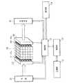
まず、本発明の第1の実施形態にかかる光CT装置の構成について説明する。図1は、本発明の第1の実施形態にかかる光CT装置の構成図である。本実施形態の光CT装置は、被検体40の光吸収特性を測定するための測定機構と、測定機構より得られた実測データを演算処理することにより被検体40の吸収係数分布画像を再構成する演算機構とを備えている。
【0019】
演算機構は、本装置全体の動作を制御するマイクロプロセッサーユニット(MPU)を有する制御部11と、あらかじめ決められたアルゴリズムにもとづいて、被検体40の吸収係数分布画像を再構成するための演算処理を行う演算部12と、演算部12が演算処理の際に使用する種々のデータなどを格納するための記憶部13と、上記演算処理により得られた被検体40の吸収係数分布画像などを表示するための表示部14とを備えている。
【0020】
また、測定機構は、被検体40に光を投射するための投光部と、投光部から投射され、被検体40を透過して成る透過光強度を測定するための受光部とを備えている。
【0021】
投光部は、近赤外光を出射する光源21と、1入力n(nは自然数)出力の投光側光スイッチ22と、n本の投光(照射)用光ファイバーF1〜Fnとから構成されている。投光側光スイッチ22の光入力端は光源21の光出力端に接続されており、また投光側光スイッチ22のn個の光出力端は、n本の投光用光ファイバーF1〜Fnのそれぞれの光入力端に接続されている。n本の投光用光ファイバーF1〜Fnの光出力端は、同一平面上に所定の間隔で並べられ、機械的に固定されている。
【0022】
また、投光側光スイッチ22は制御部11からの切り替え制御に従って、n個中一つの分岐路のみを選択的にオン、残余の分岐路をオフにする機能を有している。この機能により、光源21から出射された光は、n本の投光用光ファイバーF1〜Fnのいずれかに個別排他的に導入され、光の導入された投光用光ファイバーFkの光出力端のみから被検体40に向けて投射(照射)される。従って、被検体40内の異なる部位に向けて順次光を投射することが可能となっている。
【0023】
一方受光部は、m(mは自然数)本の受光(検出)用光ファイバーB1〜Bmと、m入力1出力の受光側光スイッチ32と、光電変換デバイスなどを有する光検出部31とから構成されている。受光側光スイッチ32のm個の光入力端は、m本の受光用光ファイバーB1〜Bmのそれぞれの光出力端に接続されており、また、受光側光スイッチ32の光出力端は光検出部31の光入力端に接続されている。m本の受光用光ファイバーB1〜Bmの光入力端は、同一平面上に所定の間隔で並べられ、機械的に固定されている。
【0024】
また、受光側光スイッチ32は制御部11からの切り替え制御に従って、m個中一つの分岐路のみを選択的にオン、残余の分岐路をオフにする機能を有している。この機能により、m本の受光用光ファイバーB1〜Bmに入射した光は個別排他的に光検出部31に導入される。従って、被検体40の位置の異なる部位から発せられた透過光の光強度を順次測定することが可能となっている。
【0025】
被検体40の光吸収特性を測定する時は、投光用光ファイバーF1〜Fnの光出力端を被検体40の一側端に対向あるいは接触させ、光源21から出射された光を各投光用光ファイバーF1〜Fnから順次被検体40の各部位に投射する。また、受光用光ファイバーB1〜Bmの光入力端は、被検体40の一側端に対向あるいは接触させると共に、投光用光ファイバーF1〜Fnの光出力端にも対向する位置に配置し、被検体40の内部を透過して成る透過光を各受光用光ファイバーB1〜Bmから順次光検出部31に導入し、光電変換およびA/D変換することにより測定データを得る。
【0026】
次に本実施形態の光CT装置の作用及び被検体40内各部位の吸収係数分布画像の再構成方法について説明する。
【0027】
図2は本実施形態における画像再構成方法を示すフローチャートである。本方法は、被検体40に光を投射し、透過光の光強度を計測する第1の工程(S10)と、モンテカルロ法により被検体40内の各体積要素における透過光の光路長(光の行路長)分布を求める第2の工程(S20)と、第1の工程(S10)により測定された計測値と第2の工程(S20)にて計算された透過光の光路長分布とから、被検体40の光吸収特性に基づく特徴量である未知吸収係数の分布画像を計算する第3の工程(S30)とから成り立っている。
【0028】
上記3つの工程を順次説明していく。図3は、第1の工程(S10)を示すフローチャートである。第1の工程(S10)は、被検体40に光を投射し、透過光の強度を測定する工程である。具体的には、まず、制御部11が投光側光スイッチ22を切り替えることによって投光用光ファイバーF1〜Fnのうちひとつを選択する。光スイッチ22によって選択された投光用光ファイバーFkは、光源21から出射された光を被検体40に向けて投射する(S11)。
【0029】
選択された投光用光ファイバーFkの光出力端から投射され、被検体40を透過して成る透過光は、受光用光ファイバーB1〜Bmのそれぞれに入射する。制御部11は受光側光スイッチ32を切り替えることにより、受光用光ファイバーB1〜Bmに入射した光を順次光検出部31に導入する。光検出部31は入射光強度を検出し、光電変換及びA/D変換後に制御部11に計測データを送出する(S12)。データを受け取った制御部11は、記憶部13の該当エリアに入射光強度を記録する。
【0030】
受光用光ファイバーB1〜Bmへの入射光の計測が全て終了したら、制御部11が投光側光スイッチ22を切り替えることによって、投光用光ファイバーを切り替え、上記と同様に受光用光ファイバーB1〜Bmに入射した光強度を順次計測し、記録する。投光用光ファイバーF1〜Fnの全てについて上記の操作を繰り返し、計測した光強度を記憶部13に記録する。
【0031】
図4は、第2の工程(S20)を示すフローチャートである。第2の工程(S20)は被検体を体積要素に分割し、各体積要素における透過光の光路長分布を求める工程である。
【0032】
まず被検体40を複数の体積要素に分割したモデルを計算機上に設定する(S21)。体積要素の数、大きさ及び形状は、必要な空間分解能を考慮した上で任意に設定することが可能である。
【0033】
次に、光源S及び検出器Dを設定し、光源Sから投射された光子が検出器Dに入射するまでの経路をモンテカルロ法によって計算する。光源Sは第1の工程において被検体40に光を投射した投光用光ファイバーF1〜Fnのいずれかの光出力端を模擬し、同様に検出器Dは受光用光ファイバーB1〜Bmのいずれかの光入力端を模擬する。具体的な手順としては、まず光源Sから仮想的に光子を発生させ(S22)、モンテカルロ法を用いて、光子が各体積要素を通過する行路長Lを求める(S23)。1個の光子に対して、ある体積要素内を光子が通過する光路長が1つずつ求められるので、この操作を複数回行うことにより、その体積要素を行路長Lで通過する光子の頻度分布、つまりその体積要素における光路長分布P(L)が求まる。1つの光源Sと検出器Dとの組み合わせに対して、計算精度に必要な分布が得られるまでこの操作を繰り返す。この操作は全ての体積要素について行なわれるので、体積要素の位置を(x,y,z)で表せば位置(x,y,z)に存在する体積要素における光路長分布はP(x,y,z,L)で表される。上記の操作を全ての光源S及び検出器Dとの組み合わせにおいて実施し、結果を記憶部13に保存する(S24)。
【0034】
図5は、第3の工程(S30)を示すフローチャートである。第3の工程(S30)は、第1の工程(S10)により測定された計測値と第2の工程(S20)にて計算された透過光の光路長分布とから、被検体40の光吸収特性に基づく特徴量である未知吸収係数の分布画像を計算する工程である。
【0035】
以下、吸収係数分布を計算する手順を具体的に述べていく。体積要素の位置(x,y,z)における吸収係数をU(x,y,z)とすれば光源Sから出射され、検出器Dで受光される光強度に対して位置(x,y,z)にある体積要素が与える減衰の影響ESDは
【0036】
【数1】
【0037】
【数2】
【0038】
【数3】
【0039】
また、基準検出光量I0SDから検出光量ISDに変化した場合、変化量ΔISDは基準吸収係数U0として
【0040】
【数4】
【0041】
ここで、式(3)または式(4)を用いて吸収係数Uを解き、吸収係数分布画像を再構成するためには、被検体を分割した体積要素数以上の方程式が必要であり、このことは、被検体を分割した体積要素数以上の光源Sと検出器Dとの組み合わせが必要であることを意味する。例えば、立方体の被検体を5×5×5の小さな立方体の体積要素に分割した場合、式(3)または式(4)は125個以上必要となる。よって、本実施形態の第1の工程(S10)において、全ての投光用光ファイバーF1〜Fn及び受光用光ファイバーB1〜Bmの組み合わせについて透過光強度を計測し、第2の工程(S20)においても同様に、全ての光源S及び検出器Dの組み合わせについて各体積要素の光路長分布を求めたが、これらの組み合わせの数は分割した体積要素数以上でなくてはならず、また、分割した体積要素数以上となれば、全ての組み合わせについて実施する必要はない。
【0042】
式(3)または式(4)は、シンプレックス法、共役勾配法やその他の非線形最小自乗法を用いて解くことが可能であり、これらの方程式を解くことにより吸収係数Uの再構成画像を得ることができる(S31)。解かれた結果は、表示部14に表示される(S32)。
【0043】
上記第2の工程(S20)及び第3の工程(S30)は、以下の方法に置き換えることもできる。すなわち、上記第2の工程(S20)においては、各体積要素ごとに独立に光路長分布を求めていたが、ここでは、体積要素全体にわたる光路を考慮した光路長分布PSD(L1,…,Ln)を求める。ここで、Lj(j=1〜n)はj番目の体積要素内を通過した光路長を表しており、nは分割した体積要素の数である。体積要素全体にわたる光路を考慮した光路長分布PSD(L1,…,Ln)を用いると、検出光量ISDは、
【0044】
【数5】
【0045】
同様に、基準検出光量I0SDから検出光量ISDに変化した場合の変化量ΔISDは、j番目の体積要素内の基準吸収係数をU0j(j=1〜n)として、
【0046】
【数6】
【0047】
式(5)あるいは式(6)においては、光路長分布PSD(L1、…、Ln)を用いて吸収係数Uを計算することにより、より精度の高い吸収係数分布の計算が可能となる。
【0048】
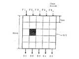
以下に、本実施形態によって被検体40の吸収係数分布画像を再構成した第1の実施例を示す。図6は、本実施例における被検体40と投光用光ファイバーF1〜F5、受光用光ファイバーB1〜B5の位置関係を示したものである。本実施例は、簡単のため被検体40、投光用光ファイバーF1〜F5の光出力端面及び受光用光ファイバーB1〜B5の光入力端面を同一平面上にもつ2次元モデルとして考える。被検体40は50mm×50mmの正方形の構造をしており、この被検体を25個の10mm×10mmの正方形の体積要素に分割する。投光用光ファイバーF1〜F5は正方形である被検体40のある1辺に面した5個の体積要素にそれぞれ光を投射できるように配置されている。また、受光用光ファイバーB1〜B5は、投光用光ファイバーF1〜F5の光出力端面が対向している被検体40の1辺の対辺に面する5個の体積要素から出射する光をそれぞれ検出できるように設置されている。
【0049】
被検体40としては散乱係数1.0mm-1、吸収係数0.0mm-1の組織を形成し、図6の黒塗りの部分の体積要素のみが吸収係数0.01mm-1の吸収体になっているモデルを作った。
【0050】
この被検体40において、図2から図5のフローチャートで示したアルゴリズムを適用し、吸収係数分布画像を再構成した。第1の工程(S10)における透過光の強度計測は、被検体を25個の体積要素に分割したため、全ての光源Sと全ての検出器Dとの組み合わせの25通りで実施した。また、第2の工程(S20)においては、1つの光源Sと検出器Dとの組み合わせに対して、約1億個の光子を仮想的に発生させ、モンテカルロ法を用いて光路長分布を求めた。第3の工程(S30)において、式(3)を解く方法としてはシンプレックス法を用い、シンプレックス法における残差の自乗和が0.02以下となった時点で収束したと判定し、計算を打ち切った。
【0051】
再構成された吸収係数分布画像は図7の如くになる。0.01mm-1の吸収係数を持つ吸収体が存在する体積要素における吸収係数の計算結果は0.00944mm-1となり、その他吸収係数が0.0mm-1である体積要素における吸収係数の計算結果は1.0×10⁻⁵以下となっている。吸収体が存在する体積要素の吸収係数の計算結果は、シンプレックス法の収束判定に用いるしきい値を小さくすることにより、理論上限りなく0.01mm-1に近づくことが期待できる。
【0052】
次に、本方法によって被検体40の吸収係数分布を計算した第2の実施例を以下に示す。図8は本実施例で用いた被検体及び光の入射位置、光検出位置を示している。第一の実施例と同様に、簡単のため二次元モデルの被検体40を用いている。被検体40は、表層から10mmの深さまでが吸収係数μ1、それより深部の吸収係数がμ2である二層モデルを用いた。今回は散乱係数を1.0mm-1、吸収係数μ1を0.01mm-1、μ2を0.02mm-1とした。
【0053】
また、投光用光ファイバーF1を被検体40の表層部の1カ所に対向させて設置し、4つの受光用光ファイバーB1〜B4を投光用光ファイバーF1からそれぞれ10mm,15mm、20mm,25mm離れた位置に直線上に並べ、被検体の表層部に接触させた。
【0054】
まず、投光用光ファイバーF1から出射され、被検体40を透過して成る透過光の強度を4つの受光用光ファイバーB1〜B4を通して光検出部で測定した。次に、モンテカルロ法をもちいて、表層部、深部の2つの体積要素について光路長分布を計算した。その後に、各体積要素、つまり表層部と深部の2つの体積要素について、シンプレックス法を用いて吸収係数を計算した。その結果はμ1=0.01001mm-1、μ2=0.01992mm-1となった。
【0055】
さらに、今回は被検体を2つの体積要素に分割しているため、光源Sと2つの検出器Dとの組み合わせがあれば各体積要素の吸収係数を求めることが可能である。そこで、4つの受光用光ファイバーB1〜B4のうち、光源から20mm及び25mm離れた位置に設置された2つの受光用光ファイバーF2、F3だけを用いて吸収係数を計算してみたが、4つの受光用光ファイバーF1〜F4を用いた場合と同様の結果が得られた。
【0056】
また今回は層の厚さを10mmで既知としたが、厚さを変数とし、それぞれの厚さにおける光路長分布を求めておけば、任意の厚さの層状組織について計算が可能である。
【0057】
さらに、本実施形態にかかる光CT装置及び画像再構成方法の効果について説明する。本実施形態の光CT装置及び画像再構成方法を用いることにより、上記実施例における計算結果でも示したように、被検体40の吸収係数がゼロあるいはゼロに近い場合でなくとも、非常に高精度な吸収係数分布画像が再構成できる。また、被検体40を微小な体積要素に分割しなくても、高精度な吸収係数分布画像が得られるため、計算時間も非常に早くなる。
【0058】
次に本発明の第2の実施形態にかかる光CT装置及び画像再構成方法について説明する。第1の実施形態では被検体40に投射する投射光として連続光を用いたが、第2の実施形態においてはパルス光を使用する。装置の基本構成は第1の実施形態と同じで図1に示すとおりであるが、光源21から所定のタイミングでパルス光を出射させ、そのタイミングに同期して入射側光スイッチ22を順次切り替えることにより被検体40内の異なる部位に対してパルス光を投射する。受光側光スイッチ32も上記タイミングに同期して切り替えることにより、投光側光ファイバーF1〜Fn、受光側光ファイバーB1〜Bmまでの全て、あるいは必要数以上の組み合わせについて透過光強度を検出し、記憶部13に記憶する。以降の処理、つまり第2の工程以降は第1の実施形態と同様に実施し、吸収係数分布画像を再構成する。
【0059】
第2の実施形態において、投射光Hsが被検体40に投射された場合の検出光Qtをシミュレーションすると、図9に示す如く、時間分解波形Qtが求められる。更に、実際の被検体40について同じ条件で測定しても、図10に示す如く同様の時間分解波形Qtが得られる。ここで、検出光Qtは時間分解波形となるので、例えば図9における点線部分より左側、つまりある時刻より前の光情報のみを用いても吸収係数分布画像の再構成が可能である。また、この場合は被検体40内を短時間で伝播してきた光についてのみ処理することになるので、透過光強度に影響を与える被検体内の領域が相対的に狭まり、連続光を用いるよりも鮮明な画像を得ることができる。
【0060】
次に本発明の第3の実施形態にかかる光CT装置について説明する。第1の実施形態では被検体40に投射する投射光として連続光を用いたが、第3の実施形態においては変調光を使用する。装置の基本構成は第1の実施形態と同じで図1に示すとおりであるが、光源21から変調光を出射し、入射側光スイッチ22を順次切り替えることにより被検体40に対して変調光を投射する。投光側光ファイバーF1〜Fn、受光側光ファイバーB1〜Bmまでの全て、あるいは必要数以上の組み合わせについて透過光強度を検出し、記憶部13に記憶する。以降の処理、つまり第2の工程以降は第1の実施形態と同様に実施し、吸収係数分布画像を再構成する。
【0061】
第3の実施形態において、変調光を使用することにより、その位相情報を用いて鮮明な再構成画像を得ることが可能となる。
【0062】
上記の第1から第3の実施形態においては、投光用光ファイバーF1〜Fnの光出力端面及び受光用光ファイバーB1〜Bmの光入力端面は平面上に2次元配置され、制御部11によって光を被検体40に投射する投射用光ファイバーおよび、光を光検出部31に導入する受光用光ファイバーを順次選択していた。しかし、これは、光出力端面及び光入力端面が直線上に並んだ光ファイバー列をスキャンしながら投光及び受光を行っても良い。また、光源21及び光検出部31を2次元的にスキャンして投光及び受光を行っても良い。
【0063】
また、上記の第1から第3の実施形態においては、光源21から出射された光を各投光用光ファイバーF1〜Fnに導入するために、投光側光スイッチ22を用いていた。しかしこれは、投光用光ファイバーF1〜Fnと同数の光源21を備え、各光源21の光出力端と各投光用光ファイバーF1〜Fnの光入力端とを直接接続し、各光源21を所定のタイミングでオンオフ制御することによっても実現可能である。同様に、受光側光スイッチ32を用いる代わりに、受光用光ファイバーB1〜Bmと同数の光検出部31を備え、受光用光ファイバーB1〜Bmに導入された透過光の強度を同時に計測することも可能である。
【0064】
また、散乱係数を変数としてそれぞれの散乱係数の場合における光路長分布を求めておけば、散乱係数、吸収係数を同時に求めることも可能である。
【0065】
【発明の効果】
本発明においては、被検体内各体積要素の光吸収特性に基づく特徴量の計算時に、従来のような被検体の各体積要素毎の平均光路長を用いる代わりに、各体積要素毎の光路長分布を用いた。その結果、あらゆる吸収係数の場合に対しても実効的な光路長が得られ、吸収係数の大きさや分割する体積要素の大きさの制約なく正確な計算が可能となる。
【図面の簡単な説明】
【図1】本発明の第1の実施形態にかかる光CT装置の構成図である。
【図2】本発明の第1の実施形態にかかる画像再構成方法を示すフローチャートである。
【図3】本発明の第1の実施形態にかかる画像再構成方法の第1の工程を示すフローチャートである。
【図4】本発明の第1の実施形態にかかる画像再構成方法の第2の工程を示すフローチャートである。
【図5】本発明の第1の実施形態にかかる画像再構成方法の第3の工程を示すフローチャートである。
【図6】本発明の第1の実施例で用いた被検体及び光の入射位置、光検出位置を示した図である。
【図7】本発明の第1の実施例における吸収係数分布画像再構成結果を示した図である。
【図8】本発明の第2の実施例で用いた被検体及び光の入射位置、光検出位置を示した図である。
【図9】本発明の第2の実施形態における入射光と検出光の時間分解波形をシミュレートした結果を示した図である。
【図10】本発明の第2の実施形態における入射光と検出光の時間分解波形を実測した結果を示した図である。
【符号の説明】
11…制御部、12…演算部、13…記憶部、14…表示部、21…光源、22…入射側光スイッチ、31…光検出部、32…受光側光スイッチ、40…被検体、F1〜Fn…投光用光ファイバー、B1〜Bm…受光用光ファイバー[0001]
BACKGROUND OF THE INVENTION
The present invention relates to an optical CT apparatus and an image reconstruction method for projecting light onto a subject such as a living body and reconstructing a feature amount image based on the light absorption characteristics of the subject from the transmitted light intensity.
[0002]
[Prior art]
Currently, X-ray CT, ultrasonic CT, MRI, and the like are used as medical diagnostic imaging apparatuses. In addition to these, recently, near infrared light has high permeability to living tissue, can measure oxygen concentration in living tissue, and is safer than X-rays, etc. Optical CT is attracting attention.
[0003]
The optical CT device mainly detects light transmitted from the light projection unit that projects light to each part of the subject and the light projection unit, detects transmitted light that passes through the subject, and measures transmitted light intensity. And an arithmetic unit for reconstructing an absorption coefficient distribution image inside the subject from the measured light intensity and optical path.
[0004]
As an image reconstruction method, the subject is divided into a plurality of minute volume elements, and the absorption of each volume element is calculated from the average optical path length of each volume element in the subject obtained by the Monte Carlo method and the measured transmitted light intensity. Methods for determining the substance concentration are known (Japanese Patent Laid-Open Nos. 3-505922 and 8-29329).
[0005]
[Problems to be solved by the invention]
In a conventional optical CT apparatus, when reconstructing an absorption coefficient distribution image of a subject, the average optical path length of photons passing through each volume element is used to determine the influence on attenuation of detected transmitted light. It was. However, if the average optical path length is used, a relatively accurate absorption coefficient distribution image can be obtained when the absorption coefficient inside the subject is zero or close to zero. However, there is a problem that the calculation result of the absorption coefficient is different from the absorption coefficient of the actual tissue.
[0006]
An object of the present invention is to solve the above problems and to provide an optical CT apparatus and an image reconstruction method capable of calculating an accurate absorption coefficient of a subject regardless of the magnitude of the absorption coefficient. To do.
[0007]
[Means for Solving the Problems]
In order to solve the above-described problems, an optical CT apparatus of the present invention includes:When the first, second, and third numbers are all natural numbers and the product of the first number and the second number is greater than or equal to the third number, Project light individually onto the subjectFirst number The light projecting means having the light output position and the transmitted light formed by transmitting the projection light projected by the light projecting means through the subject are individually received.Second number A light detecting means having a light receiving position ofThird number Assuming a virtual light projecting means having a first number of virtual output positions for projecting light under the same conditions as the first number of light output positions possessed by the light projecting means And a first number of virtual light output positions, assuming a virtual light detection means having a second number of virtual light receiving positions that receive light under the same conditions as a second number of light receiving positions of the light detection means. And the second number of virtual light receiving positions, the light path length for each of the third number of volume elements when light is projected from any virtual light output position and light is received at any light receiving position. A first calculation means for calculating an optical path length distribution P (L) representing the frequency of photons passing through L, an optical path length distribution P (L) of each volume element obtained by the first calculation means, and a light projection Light transmitted through the object measured using the means and the light detection means And a light intensity, and second calculating means for calculating a feature quantity based on light absorption characteristics of each volume element, comprising the.
[0008]
The light projected by the light projecting means is scattered within the subject and partly absorbed. The transmitted light intensity of the light transmitted through the subject is measured by the light detection means. Thereafter, the optical path length distribution in each volume element obtained by dividing the subject into a plurality of parts is calculated by the first calculation means. Finally, the second calculation means accurately obtains a feature quantity based on the light absorption characteristics of each volume element from the actually measured transmitted light intensity and the calculated optical path length distribution.
[0009]
The light projecting means may emit continuous light. By using a light projecting means that emits continuous light, a simple apparatus configuration can be obtained.
[0010]
In addition, the light projecting unit may emit pulsed light, and the light detecting unit may perform time-division measurement of transmitted light transmitted through the subject. By using a light projecting means characterized by emitting pulsed light and a light detecting means characterized by time-division measurement of transmitted light, time-division information of the light intensity signal can be used.
[0011]
Furthermore, the light projecting means may emit modulated light. By using the light projecting means that emits the modulated light, the phase information of the light intensity signal can be used.
[0012]
Further, the image reconstruction method of the present invention includes:When the first, second, and third numbers are all natural numbers and the product of the first number and the second number is greater than or equal to the third number, the first number And projecting light individually to a subject (excluding a human) using a light projecting means having a light output position ofSecond number A first step of individually detecting the transmitted light formed by transmitting the projection light projected by the light projecting means through the subject using the light detecting means having the light receiving position;Third number Assuming a virtual light projecting means having a first number of virtual output positions for projecting light under the same conditions as the first number of light output positions possessed by the light projecting means And a first number of virtual light output positions, assuming a virtual light detection means having a second number of virtual light receiving positions that receive light under the same conditions as a second number of light receiving positions of the light detection means. And the second number of virtual light receiving positions, the light path length for each of the third number of volume elements when light is projected from any virtual light output position and light is received at any light receiving position. A second step of calculating an optical path length distribution P (L) representing the frequency of photons passing through L, an optical path length distribution P (L) of each volume element obtained by the second step, and a first step In the object measured using the light projecting means and the light detecting means in And a light intensity of the transmitted light that is characterized by comprising a third step of calculating a feature quantity based on light absorption characteristics of each volume element, the.
[0013]
FirstProcess Then, the transmitted light intensity of the light projected by the light projecting means and transmitted through the subject is measured by the light detecting means. Also the secondProcess Then, the optical path length distribution in each volume element obtained by dividing the subject into a plurality of parts is calculated. ThirdProcess In FIG. 5, a feature quantity based on the light absorption characteristics of each volume element is accurately obtained from the actually measured transmitted light intensity and the calculated optical path length distribution.
[0014]
The light projecting means may emit continuous light. By using a light projecting means that emits continuous light, a simple apparatus configuration can be obtained.
[0015]
In addition, the light projecting unit may emit pulsed light, and the light detecting unit may perform time-division measurement of transmitted light transmitted through the subject. By using a light projecting means characterized by emitting pulsed light and a light detecting means characterized by time-division measurement of transmitted light, time-division information of the light intensity signal can be used.
[0016]
Furthermore, the light projecting means may emit modulated light. By using the light projecting means that emits the modulated light, the phase information of the light intensity signal can be used.
[0017]
DETAILED DESCRIPTION OF THE INVENTION
An optical CT apparatus and an image reconstruction method according to a first embodiment of the present invention will be described with reference to the drawings.
[0018]
First, the configuration of the optical CT apparatus according to the first embodiment of the present invention will be described. FIG. 1 is a configuration diagram of an optical CT apparatus according to the first embodiment of the present invention. The optical CT apparatus of the present embodiment reconstructs an absorption coefficient distribution image of the subject 40 by calculating a measurement mechanism for measuring the light absorption characteristics of the subject 40 and actual measurement data obtained from the measurement mechanism. And an arithmetic mechanism for performing the operation.
[0019]
The calculation mechanism is a calculation unit for reconstructing an absorption coefficient distribution image of the subject 40 based on a
[0020]
The measurement mechanism includes a light projecting unit for projecting light onto the subject 40 and a light receiving unit for measuring transmitted light intensity projected from the light projecting unit and transmitted through the subject 40. Yes.
[0021]
The light projecting unit includes a
[0022]
The light-projecting side
[0023]
On the other hand, the light receiving unit includes m (m is a natural number) light receiving (detection) optical fibers B1 to Bm, a light receiving side
[0024]
The light-receiving side
[0025]
When measuring the light absorption characteristics of the subject 40, the light output ends of the projecting optical fibers F1 to Fn are made to face or contact one side end of the subject 40, and the light emitted from the
[0026]
Next, the operation of the optical CT apparatus of the present embodiment and the method for reconstructing the absorption coefficient distribution image of each part in the subject 40 will be described.
[0027]
FIG. 2 is a flowchart showing an image reconstruction method in this embodiment. This method projects the light onto the subject 40 and measures the first light intensity of the transmitted light.Process (S10) and a second optical path length (light path length) distribution of transmitted light in each volume element in the subject 40 by the Monte Carlo method.Process (S20) and the firstProcess The measured value measured by (S10) and the secondProcess A third image for calculating an unknown absorption coefficient distribution image, which is a feature amount based on the light absorption characteristics of the subject 40, from the optical path length distribution of the transmitted light calculated in (S20).Process (S30).
[0028]
The above threeProcess Will be explained sequentially. FIG. 3 shows the firstProcess It is a flowchart which shows (S10). FirstProcess (S10) projects light onto the subject 40 and measures the intensity of transmitted light.Process It is. Specifically, first, the
[0029]
The transmitted light projected from the light output end of the selected light projecting optical fiber Fk and transmitted through the subject 40 enters each of the light receiving optical fibers B1 to Bm. The
[0030]
When all the measurement of the incident light to the light receiving optical fibers B1 to Bm is completed, the
[0031]
FIG. 4 shows the secondProcess It is a flowchart which shows (S20). SecondProcess (S20) divides the subject into volume elements and obtains the optical path length distribution of the transmitted light in each volume element.Process It is.
[0032]
First, a model obtained by dividing the subject 40 into a plurality of volume elements is set on the computer (S21). The number, size, and shape of the volume elements can be arbitrarily set in consideration of the necessary spatial resolution.
[0033]
Next, the light source S and the detector D are set, and the path until the photon projected from the light source S enters the detector D is calculated by the Monte Carlo method. The light source S is the
[0034]
FIG. 5 shows the thirdProcess It is a flowchart which shows (S30). ThirdProcess (S30) is the firstProcess The measured value measured by (S10) and the secondProcess From the optical path length distribution of the transmitted light calculated in (S20), a distribution image of an unknown absorption coefficient that is a feature amount based on the light absorption characteristics of the subject 40 is calculated.Process It is.
[0035]
The procedure for calculating the absorption coefficient distribution will be specifically described below. If the absorption coefficient at the position (x, y, z) of the volume element is U (x, y, z), the position (x, y, z) with respect to the light intensity emitted from the light source S and received by the detector D z) Effect of damping on volume elements in ESD Is
[0036]
[Expression 1]
[0037]
[Expression 2]
[0038]
[Equation 3]
[0039]
Further, the reference detection light quantity I0SD Detected light intensity ISD Change to ΔISD Is the standard absorption coefficient U0 As
[0040]
[Expression 4]
[0041]
Here, in order to solve the absorption coefficient U using Equation (3) or Equation (4) and reconstruct the absorption coefficient distribution image, an equation equal to or greater than the number of volume elements obtained by dividing the subject is required. This means that a combination of the light sources S and detectors D equal to or larger than the number of volume elements obtained by dividing the subject is necessary. For example, when a cubic object is divided into small cubic volume elements of 5 × 5 × 5, 125 or more expressions (3) or (4) are required. Therefore, the first of this embodimentProcess In (S10), the transmitted light intensity is measured for all combinations of the light projecting optical fibers F1 to Fn and the light receiving optical fibers B1 to Bm.Process Similarly, in (S20), the optical path length distribution of each volume element was obtained for all combinations of the light source S and the detector D. Moreover, if it becomes more than the divided | segmented volume element number, it is not necessary to implement about all the combinations.
[0042]
Equation (3) or equation (4) can be solved by using a simplex method, a conjugate gradient method, or other nonlinear least square method, and a reconstructed image of the absorption coefficient U is obtained by solving these equations. (S31). The solved result is displayed on the display unit 14 (S32).
[0043]
SecondProcess (S20) and the thirdProcess (S30) can be replaced with the following method. That is, the secondProcess In (S20), the optical path length distribution is obtained independently for each volume element, but here, the optical path length distribution PSD (L1,..., Ln) considering the optical path over the entire volume element is obtained. Here, Lj (j = 1 to n) represents the optical path length that has passed through the j-th volume element, and n is the number of divided volume elements. When the optical path length distribution PSD (L1,..., Ln) considering the optical path over the entire volume element is used, the detected light quantity ISD is
[0044]
[Equation 5]
[0045]
Similarly, the reference detection light amount I0SD Detected light intensity ISD Amount of change ΔI when changed toSD Gives the reference absorption coefficient in the jth volume element as U0 j (j = 1 to n)
[0046]
[Formula 6]
[0047]
In Expression (5) or Expression (6), the optical path length distribution PSD By calculating the absorption coefficient U using (L1,..., Ln), it is possible to calculate the absorption coefficient distribution with higher accuracy.
[0048]
Below, the 1st Example which reconfigure | reconstructed the absorption coefficient distribution image of the subject 40 by this embodiment is shown. FIG. 6 shows the positional relationship between the subject 40, the light projecting optical fibers F1 to F5, and the light receiving optical fibers B1 to B5 in this embodiment. In this embodiment, for the sake of simplicity, it is considered as a two-dimensional model having the subject 40, the light output end faces of the projecting optical fibers F1 to F5, and the light input end faces of the light receiving optical fibers B1 to B5 on the same plane. The subject 40 has a 50 mm × 50 mm square structure, and the subject is divided into 25 10 mm × 10 mm square volume elements. The projecting optical fibers F1 to F5 are arranged so that light can be projected onto five volume elements facing one side of the subject 40 that is square. The light receiving optical fibers B1 to B5 can respectively detect light emitted from five volume elements facing opposite sides of one side of the subject 40 with which the light output end faces of the light projecting optical fibers F1 to F5 are opposed. It is installed as follows.
[0049]
The subject 40 has a scattering coefficient of 1.0 mm.-1 , Absorption coefficient 0.0mm-1 Only the volume element of the black-painted portion in FIG. 6 has an absorption coefficient of 0.01 mm.-1 I made a model that is an absorber.
[0050]
In this subject 40, the absorption coefficient distribution image was reconstructed by applying the algorithm shown in the flowcharts of FIGS. FirstProcess The intensity measurement of the transmitted light in (S10) was performed with 25 combinations of all light sources S and all detectors D because the subject was divided into 25 volume elements. Also the secondProcess In (S20), about 100 million photons were virtually generated for a combination of one light source S and detector D, and the optical path length distribution was obtained using the Monte Carlo method. ThirdProcess In (S30), the simplex method was used as a method for solving the equation (3), and when the sum of squares of the residuals in the simplex method was 0.02 or less, it was determined that the convergence occurred, and the calculation was terminated.
[0051]
The reconstructed absorption coefficient distribution image is as shown in FIG. 0.01mm-1 The calculation result of the absorption coefficient in a volume element in which an absorber having an absorption coefficient of-1 Other absorption coefficient is 0.0mm-1 The calculation result of the absorption coefficient in the volume element is 1.0 × 10-Five It is as follows. The calculation result of the absorption coefficient of the volume element in which the absorber exists is theoretically limited to 0.01 mm by reducing the threshold value used for determining the convergence of the simplex method.-1 Can be expected to approach.
[0052]
Next, a second embodiment in which the absorption coefficient distribution of the subject 40 is calculated by this method will be described below. FIG. 8 shows the subject, the light incident position, and the light detection position used in this example. Similar to the first embodiment, a two-
[0053]
Further, the light projecting optical fiber F1 is placed facing one place on the surface layer portion of the subject 40, and the four light receiving optical fibers B1 to B4 are separated from the light projecting optical fiber F1 by 10 mm, 15 mm, 20 mm, and 25 mm, respectively. Were arranged on a straight line and brought into contact with the surface layer of the subject.
[0054]
First, the intensity of the transmitted light emitted from the light projecting optical fiber F1 and transmitted through the subject 40 was measured by the light detection unit through the four light receiving optical fibers B1 to B4. Next, using the Monte Carlo method, the optical path length distribution was calculated for the two volume elements of the surface layer portion and the deep portion. Thereafter, an absorption coefficient was calculated for each volume element, that is, two volume elements of the surface layer portion and the deep portion by using a simplex method. The result is μ1 = 0.01001mm-1 , Μ2 = 0.01992 mm-1 It became.
[0055]
Furthermore, since the subject is divided into two volume elements this time, if there is a combination of the light source S and the two detectors D, the absorption coefficient of each volume element can be obtained. Therefore, the absorption coefficient was calculated using only two light receiving optical fibers F2 and F3 installed at positions 20 mm and 25 mm away from the light source among the four light receiving optical fibers B1 to B4. The same result as that obtained when the optical fibers F1 to F4 were used was obtained.
[0056]
In addition, although the thickness of the layer is known to be 10 mm this time, if the thickness is a variable and the optical path length distribution at each thickness is obtained, the calculation can be performed for a layered structure having an arbitrary thickness.
[0057]
Further, effects of the optical CT apparatus and the image reconstruction method according to the present embodiment will be described. By using the optical CT apparatus and the image reconstruction method according to the present embodiment, even when the absorption coefficient of the subject 40 is not zero or close to zero, as shown in the calculation results in the above example, extremely high accuracy is achieved. A simple absorption coefficient distribution image can be reconstructed. In addition, since a highly accurate absorption coefficient distribution image can be obtained without dividing the subject 40 into minute volume elements, the calculation time is very fast.
[0058]
Next, an optical CT apparatus and an image reconstruction method according to the second embodiment of the present invention will be described. In the first embodiment, continuous light is used as the projection light projected on the subject 40, but in the second embodiment, pulsed light is used. The basic configuration of the apparatus is the same as that of the first embodiment as shown in FIG. 1, but pulse light is emitted from the
[0059]
In the second embodiment, when the detection light Qt when the projection light Hs is projected onto the subject 40 is simulated, a time-resolved waveform Qt is obtained as shown in FIG. Further, even if the
[0060]
Next, an optical CT apparatus according to a third embodiment of the present invention will be described. In the first embodiment, continuous light is used as the projection light projected onto the subject 40, but in the third embodiment, modulated light is used. The basic configuration of the apparatus is the same as that of the first embodiment and is as shown in FIG. 1, but the modulated light is emitted from the
[0061]
In the third embodiment, by using modulated light, it is possible to obtain a clear reconstructed image using the phase information.
[0062]
In the first to third embodiments, the light output end faces of the light projecting optical fibers F1 to Fn and the light input end faces of the light receiving optical fibers B1 to Bm are two-dimensionally arranged on a plane, and the
[0063]
In the first to third embodiments, the light projecting side
[0064]
Further, if the optical path length distribution in each scattering coefficient is obtained with the scattering coefficient as a variable, the scattering coefficient and the absorption coefficient can be obtained simultaneously.
[0065]
【The invention's effect】
In the present invention, instead of using the average optical path length for each volume element of the subject as in the prior art when calculating the feature amount based on the light absorption characteristics of each volume element in the subject, the optical path length for each volume element Distribution was used. As a result, an effective optical path length can be obtained for any absorption coefficient, and accurate calculation is possible without any restrictions on the size of the absorption coefficient or the volume element to be divided.
[Brief description of the drawings]
FIG. 1 is a configuration diagram of an optical CT apparatus according to a first embodiment of the present invention.
FIG. 2 is a flowchart showing an image reconstruction method according to the first embodiment of the present invention.
FIG. 3 shows a first image reconstruction method according to the first embodiment of the present invention;Process It is a flowchart which shows.
FIG. 4 shows a second example of the image reconstruction method according to the first embodiment of the present invention;Process It is a flowchart which shows.
FIG. 5 shows a third image reconstruction method according to the first embodiment of the present invention;Process It is a flowchart which shows.
FIG. 6 is a diagram showing a subject, a light incident position, and a light detection position used in the first embodiment of the present invention.
FIG. 7 is a diagram showing an absorption coefficient distribution image reconstruction result in the first example of the present invention.
FIG. 8 is a diagram showing a subject, a light incident position, and a light detection position used in the second embodiment of the present invention.
FIG. 9 is a diagram showing a result of simulating time-resolved waveforms of incident light and detection light in the second embodiment of the present invention.
FIG. 10 is a diagram showing a result of actual measurement of time-resolved waveforms of incident light and detection light in the second embodiment of the present invention.
[Explanation of symbols]
DESCRIPTION OF
Claims (8)
Translated fromJapanese被検体に個別に光を投射する前記第1の数の光出力位置を有する投光手段と、
前記投光手段によって投射された投射光が被検体内を透過して成る透過光を個別に受光する前記第2の数の受光位置を有する光検出手段と、
前記被検体を前記第3の数の体積要素に分割された集合体とみなし、前記投光手段が有する前記第1の数の光出力位置と同条件で光を投射する前記第1の数の仮想出力位置を有する仮想投光手段を想定するとともに、前記光検出手段が有する前記第2の数の受光位置と同条件で光を受光する前記第2の数の仮想受光位置を有する仮想光検出手段を想定して、前記第1の数の仮想光出力位置と前記第2の数の仮想受光位置との全ての組み合わせについて、任意の前記仮想光出力位置から光を投射して任意の前記受光位置で光を受光するときに前記第3の数の体積要素それぞれについて光路長Lで通過する光子の頻度を表す光路長分布P(L)を演算する第1の演算手段と、
前記第1の演算手段により求められた前記各体積要素の前記光路長分布P(L)と、前記投光手段及び前記光検出手段を用いて実測された前記被検体内を透過して成る透過光の光強度とから、前記各体積要素の光吸収特性に基づく特徴量を演算する第2の演算手段と、を備えたことを特徴とする光CT装置。When the first, second, and third numbers are all natural numbers and the product of the first number and the second number is greater than or equal to the third number,
Projecting means havingthe first number of light output positions for individually projecting light onto the subject;
A light detection means havingthe second number of light receiving positions for individually receiving the transmitted light formed by the projection light projected by the light projecting means being transmitted through the subject;
The object is regarded as an assembly divided intothe third number of volume elements, and the first number of light projects the light under the same conditions as the first number of light output positions of the light projecting means. Assuming virtual light projecting means having a virtual output position, virtual light detection having the second number of virtual light receiving positions for receiving light under the same conditions as the second number of light receiving positions of the light detecting means Assuming the means, for any combination of the first number of virtual light output positions and the second number of virtual light reception positions, light is projected from any of the virtual light output positions, and any of the light receptions First computing means for computing an optical path length distribution P (L) representing the frequency of photons passing through the optical path length L for each of the third number of volume elements when receiving light at a position;
The optical path length distribution P (L) of each volume element obtained by the first computing means, and the transmission formed through the subject measured using the light projecting means and the light detecting means. An optical CT apparatus comprising: a second computing unit that computes a feature amount based on a light absorption characteristic of each volume element from the light intensity of light.
前記第1の数の光出力位置を有する投光手段を用いて、被検体(ヒトを除く。)に個別に光を投射すると共に、前記第2の数の受光位置を有する光検出手段を用いて、前記投光手段によって投射された投射光が被検体内を透過して成る透過光を個別に検出する第1の工程と、
前記被検体を前記第3の数の体積要素に分割された集合体とみなし、前記投光手段が有する前記第1の数の光出力位置と同条件で光を投射する前記第1の数の仮想出力位置を有する仮想投光手段を想定するとともに、前記光検出手段が有する前記第2の数の受光位置と同条件で光を受光する前記第2の数の仮想受光位置を有する仮想光検出手段を想定して、前記第1の数の仮想光出力位置と前記第2の数の仮想受光位置との全ての組み合わせについて、任意の前記仮想光出力位置から光を投射して任意の前記受光位置で光を受光するときに前記第3の数の体積要素それぞれについて光路長Lで通過する光子の頻度を表す光路長分布P(L)を演算する第2の工程と、
前記第2の工程により求められた前記各体積要素の前記光路長分布P(L)と、前記第1の工程において前記投光手段及び前記光検出手段を用いて実測された前記被検体内を透過して成る透過光の光強度とから、前記各体積要素の光吸収特性に基づく特徴量を演算する第3の工程と、を備えたことを特徴とする光CTにおける画像再構成方法。When the first, second, and third numbers are all natural numbers and the product of the first number and the second number is greater than or equal to the third number,
Using the light projecting means havingthe first number of light output positions, individually projecting light onto a subject (excluding a human), and using the light detection means havingthe second number of light receiving positions. A first step of individually detecting transmitted light formed by the projection light projected by the light projecting means being transmitted through the subject;
The object is regarded as an assembly divided intothe third number of volume elements, and the first number of light projects the light under the same conditions as the first number of light output positions of the light projecting means. Assuming virtual light projecting means having a virtual output position, virtual light detection having the second number of virtual light receiving positions for receiving light under the same conditions as the second number of light receiving positions of the light detecting means Assuming the means, for any combination of the first number of virtual light output positions and the second number of virtual light reception positions, light is projected from any of the virtual light output positions, and any of the light receptions A second step of calculating an optical path length distribution P (L) representing the frequency of photons passing through the optical path length L for each of the third number of volume elements when receiving light at a position;
The optical path length distribution P (L) of each volume element obtained in the second step and the inside of the subject actually measured using the light projecting unit and the light detecting unit in the first step. An image reconstruction method for optical CT, comprising: a third step of calculating a feature amount based on the light absorption characteristics of each volume element from the light intensity of transmitted light that is transmitted.
Priority Applications (1)
| Application Number | Priority Date | Filing Date | Title |
|---|---|---|---|
| JP13243597AJP3836941B2 (en) | 1997-05-22 | 1997-05-22 | Optical CT apparatus and image reconstruction method |
Applications Claiming Priority (1)
| Application Number | Priority Date | Filing Date | Title |
|---|---|---|---|
| JP13243597AJP3836941B2 (en) | 1997-05-22 | 1997-05-22 | Optical CT apparatus and image reconstruction method |
Publications (2)
| Publication Number | Publication Date |
|---|---|
| JPH10318911A JPH10318911A (en) | 1998-12-04 |
| JP3836941B2true JP3836941B2 (en) | 2006-10-25 |
Family
ID=15081310
Family Applications (1)
| Application Number | Title | Priority Date | Filing Date |
|---|---|---|---|
| JP13243597AExpired - Fee RelatedJP3836941B2 (en) | 1997-05-22 | 1997-05-22 | Optical CT apparatus and image reconstruction method |
Country Status (1)
| Country | Link |
|---|---|
| JP (1) | JP3836941B2 (en) |
Families Citing this family (6)
| Publication number | Priority date | Publication date | Assignee | Title |
|---|---|---|---|---|
| CN1100987C (en)* | 1999-12-21 | 2003-02-05 | 华中理工大学 | Optical-fibre multi-channel living body functional imaging detection system and its equipment |
| JP4364995B2 (en) | 2000-03-21 | 2009-11-18 | 浜松ホトニクス株式会社 | Calculation method of optical path distribution inside scattering medium |
| JP2010512904A (en)* | 2006-12-19 | 2010-04-30 | コーニンクレッカ フィリップス エレクトロニクス エヌ ヴィ | Imaging opaque media |
| WO2010101525A1 (en)* | 2009-03-05 | 2010-09-10 | Agency For Science, Technology And Research | A method and system for enhancing a microscopy image |
| DE102018202096A1 (en)* | 2018-02-12 | 2019-08-14 | Carl Zeiss Smt Gmbh | PICTURE SENSOR FOR A POSITION SENSOR DEVICE, POSITION SENSOR DEVICE WITH AN IMAGE SENSOR, LITHOGRAPHIC APPARATUS WITH A POSITION SENSOR DEVICE AND METHOD FOR OPERATING AN IMAGE SENSOR |
| CN118071956B (en)* | 2024-04-24 | 2024-07-09 | 浙江杜比医疗科技有限公司 | Monte Carlo simulation method, device, equipment and storage medium |
- 1997
- 1997-05-22JPJP13243597Apatent/JP3836941B2/ennot_activeExpired - Fee Related
Also Published As
| Publication number | Publication date |
|---|---|
| JPH10318911A (en) | 1998-12-04 |
Similar Documents
| Publication | Publication Date | Title |
|---|---|---|
| JP3844815B2 (en) | Method and apparatus for measuring absorption information of scatterers | |
| EP0580414B1 (en) | Apparatus for measuring absorption information in scattering medium and method for the same | |
| US8280494B2 (en) | Apparatus and method to measure a spectroscopic characteristic in an object | |
| US9706977B2 (en) | Imaging apparatus and method | |
| US5676142A (en) | Method and apparatus for measuring scattering property and absorption property in scattering medium | |
| EP1338239B1 (en) | Measuring method and apparatus of absorption information of scattering medium | |
| WO1999061893A1 (en) | Method and device for measuring internal characteristic distribution of scattering/absorbing body | |
| JPH06221913A (en) | Method and equipment for measuring optical information of scatterer/absorber | |
| US9259158B2 (en) | Object information acquiring apparatus | |
| JP3456721B2 (en) | Photoacoustic computed tomography device | |
| JPH0961359A (en) | Concentration measuring device | |
| JP3836941B2 (en) | Optical CT apparatus and image reconstruction method | |
| US6567165B1 (en) | Concentration measuring method and apparatus for absorption component in scattering medium | |
| KR20040094409A (en) | Normalized-constraint algorithm for minimizing inter-parameter crosstalk in imaging of scattering media | |
| JPH0961343A (en) | Optical measuring method and optical measuring device | |
| CN103908239B (en) | Contactless imaging system and formation method thereof | |
| CN106455994B (en) | Photo-acoustic device | |
| JP4543774B2 (en) | Biological light measurement device | |
| JP3771339B2 (en) | Optical CT apparatus and image reconstruction method using optical CT | |
| Zaccanti et al. | Detectability of inhomogeneities within highly diffusing media | |
| JP4077477B2 (en) | Method and apparatus for measuring absorption information of scatterers | |
| JP3878943B2 (en) | Method and apparatus for measuring absorption information of scatterers | |
| JP2001510361A (en) | Method and apparatus for imaging the interior of a turbid medium | |
| JPH0454439A (en) | Method and instrument for measuring living body | |
| JP4077476B2 (en) | Method and apparatus for measuring absorption information of scatterers |
Legal Events
| Date | Code | Title | Description |
|---|---|---|---|
| A621 | Written request for application examination | Free format text:JAPANESE INTERMEDIATE CODE: A621 Effective date:20040406 | |
| A977 | Report on retrieval | Free format text:JAPANESE INTERMEDIATE CODE: A971007 Effective date:20060201 | |
| A131 | Notification of reasons for refusal | Free format text:JAPANESE INTERMEDIATE CODE: A131 Effective date:20060207 | |
| A521 | Written amendment | Free format text:JAPANESE INTERMEDIATE CODE: A523 Effective date:20060406 | |
| A131 | Notification of reasons for refusal | Free format text:JAPANESE INTERMEDIATE CODE: A131 Effective date:20060516 | |
| A521 | Written amendment | Free format text:JAPANESE INTERMEDIATE CODE: A523 Effective date:20060526 | |
| TRDD | Decision of grant or rejection written | ||
| A01 | Written decision to grant a patent or to grant a registration (utility model) | Free format text:JAPANESE INTERMEDIATE CODE: A01 Effective date:20060725 | |
| A61 | First payment of annual fees (during grant procedure) | Free format text:JAPANESE INTERMEDIATE CODE: A61 Effective date:20060728 | |
| R150 | Certificate of patent or registration of utility model | Free format text:JAPANESE INTERMEDIATE CODE: R150 | |
| S531 | Written request for registration of change of domicile | Free format text:JAPANESE INTERMEDIATE CODE: R313532 | |
| R350 | Written notification of registration of transfer | Free format text:JAPANESE INTERMEDIATE CODE: R350 | |
| FPAY | Renewal fee payment (event date is renewal date of database) | Free format text:PAYMENT UNTIL: 20100804 Year of fee payment:4 | |
| FPAY | Renewal fee payment (event date is renewal date of database) | Free format text:PAYMENT UNTIL: 20100804 Year of fee payment:4 | |
| FPAY | Renewal fee payment (event date is renewal date of database) | Free format text:PAYMENT UNTIL: 20110804 Year of fee payment:5 | |
| FPAY | Renewal fee payment (event date is renewal date of database) | Free format text:PAYMENT UNTIL: 20120804 Year of fee payment:6 | |
| FPAY | Renewal fee payment (event date is renewal date of database) | Free format text:PAYMENT UNTIL: 20120804 Year of fee payment:6 | |
| FPAY | Renewal fee payment (event date is renewal date of database) | Free format text:PAYMENT UNTIL: 20130804 Year of fee payment:7 | |
| LAPS | Cancellation because of no payment of annual fees |