JP3836136B2 - Double-wall housing, especially for automotive exhaust catalytic reactor - Google Patents
Double-wall housing, especially for automotive exhaust catalytic reactorDownload PDFInfo
- Publication number
- JP3836136B2 JP3836136B2JP51945096AJP51945096AJP3836136B2JP 3836136 B2JP3836136 B2JP 3836136B2JP 51945096 AJP51945096 AJP 51945096AJP 51945096 AJP51945096 AJP 51945096AJP 3836136 B2JP3836136 B2JP 3836136B2
- Authority
- JP
- Japan
- Prior art keywords
- jacket
- inner jacket
- double
- outer jacket
- housing
- Prior art date
- Legal status (The legal status is an assumption and is not a legal conclusion. Google has not performed a legal analysis and makes no representation as to the accuracy of the status listed.)
- Expired - Fee Related
Links
Images

Classifications
- F—MECHANICAL ENGINEERING; LIGHTING; HEATING; WEAPONS; BLASTING
- F01—MACHINES OR ENGINES IN GENERAL; ENGINE PLANTS IN GENERAL; STEAM ENGINES
- F01N—GAS-FLOW SILENCERS OR EXHAUST APPARATUS FOR MACHINES OR ENGINES IN GENERAL; GAS-FLOW SILENCERS OR EXHAUST APPARATUS FOR INTERNAL-COMBUSTION ENGINES
- F01N3/00—Exhaust or silencing apparatus having means for purifying, rendering innocuous, or otherwise treating exhaust
- F01N3/08—Exhaust or silencing apparatus having means for purifying, rendering innocuous, or otherwise treating exhaust for rendering innocuous
- F01N3/10—Exhaust or silencing apparatus having means for purifying, rendering innocuous, or otherwise treating exhaust for rendering innocuous by thermal or catalytic conversion of noxious components of exhaust
- F01N3/24—Exhaust or silencing apparatus having means for purifying, rendering innocuous, or otherwise treating exhaust for rendering innocuous by thermal or catalytic conversion of noxious components of exhaust characterised by constructional aspects of converting apparatus
- F01N3/28—Construction of catalytic reactors
- F01N3/2839—Arrangements for mounting catalyst support in housing, e.g. with means for compensating thermal expansion or vibration
- F01N3/2853—Arrangements for mounting catalyst support in housing, e.g. with means for compensating thermal expansion or vibration using mats or gaskets between catalyst body and housing
- F01N3/2864—Arrangements for mounting catalyst support in housing, e.g. with means for compensating thermal expansion or vibration using mats or gaskets between catalyst body and housing the mats or gaskets comprising two or more insulation layers
- F—MECHANICAL ENGINEERING; LIGHTING; HEATING; WEAPONS; BLASTING
- F01—MACHINES OR ENGINES IN GENERAL; ENGINE PLANTS IN GENERAL; STEAM ENGINES
- F01N—GAS-FLOW SILENCERS OR EXHAUST APPARATUS FOR MACHINES OR ENGINES IN GENERAL; GAS-FLOW SILENCERS OR EXHAUST APPARATUS FOR INTERNAL-COMBUSTION ENGINES
- F01N13/00—Exhaust or silencing apparatus characterised by constructional features
- F01N13/14—Exhaust or silencing apparatus characterised by constructional features having thermal insulation
- F—MECHANICAL ENGINEERING; LIGHTING; HEATING; WEAPONS; BLASTING
- F01—MACHINES OR ENGINES IN GENERAL; ENGINE PLANTS IN GENERAL; STEAM ENGINES
- F01N—GAS-FLOW SILENCERS OR EXHAUST APPARATUS FOR MACHINES OR ENGINES IN GENERAL; GAS-FLOW SILENCERS OR EXHAUST APPARATUS FOR INTERNAL-COMBUSTION ENGINES
- F01N2450/00—Methods or apparatus for fitting, inserting or repairing different elements
- F01N2450/02—Fitting monolithic blocks into the housing
- F—MECHANICAL ENGINEERING; LIGHTING; HEATING; WEAPONS; BLASTING
- F01—MACHINES OR ENGINES IN GENERAL; ENGINE PLANTS IN GENERAL; STEAM ENGINES
- F01N—GAS-FLOW SILENCERS OR EXHAUST APPARATUS FOR MACHINES OR ENGINES IN GENERAL; GAS-FLOW SILENCERS OR EXHAUST APPARATUS FOR INTERNAL-COMBUSTION ENGINES
- F01N2450/00—Methods or apparatus for fitting, inserting or repairing different elements
- F01N2450/22—Methods or apparatus for fitting, inserting or repairing different elements by welding or brazing
- F—MECHANICAL ENGINEERING; LIGHTING; HEATING; WEAPONS; BLASTING
- F01—MACHINES OR ENGINES IN GENERAL; ENGINE PLANTS IN GENERAL; STEAM ENGINES
- F01N—GAS-FLOW SILENCERS OR EXHAUST APPARATUS FOR MACHINES OR ENGINES IN GENERAL; GAS-FLOW SILENCERS OR EXHAUST APPARATUS FOR INTERNAL-COMBUSTION ENGINES
- F01N2470/00—Structure or shape of exhaust gas passages, pipes or tubes
- F01N2470/26—Tubes being formed by extrusion, drawing or rolling
- F—MECHANICAL ENGINEERING; LIGHTING; HEATING; WEAPONS; BLASTING
- F01—MACHINES OR ENGINES IN GENERAL; ENGINE PLANTS IN GENERAL; STEAM ENGINES
- F01N—GAS-FLOW SILENCERS OR EXHAUST APPARATUS FOR MACHINES OR ENGINES IN GENERAL; GAS-FLOW SILENCERS OR EXHAUST APPARATUS FOR INTERNAL-COMBUSTION ENGINES
- F01N2510/00—Surface coverings
- F01N2510/02—Surface coverings for thermal insulation
- Y—GENERAL TAGGING OF NEW TECHNOLOGICAL DEVELOPMENTS; GENERAL TAGGING OF CROSS-SECTIONAL TECHNOLOGIES SPANNING OVER SEVERAL SECTIONS OF THE IPC; TECHNICAL SUBJECTS COVERED BY FORMER USPC CROSS-REFERENCE ART COLLECTIONS [XRACs] AND DIGESTS
- Y02—TECHNOLOGIES OR APPLICATIONS FOR MITIGATION OR ADAPTATION AGAINST CLIMATE CHANGE
- Y02A—TECHNOLOGIES FOR ADAPTATION TO CLIMATE CHANGE
- Y02A50/00—TECHNOLOGIES FOR ADAPTATION TO CLIMATE CHANGE in human health protection, e.g. against extreme weather
- Y02A50/20—Air quality improvement or preservation, e.g. vehicle emission control or emission reduction by using catalytic converters
Landscapes
- Chemical & Material Sciences (AREA)
- Chemical Kinetics & Catalysis (AREA)
- Engineering & Computer Science (AREA)
- Health & Medical Sciences (AREA)
- Toxicology (AREA)
- Combustion & Propulsion (AREA)
- Mechanical Engineering (AREA)
- General Engineering & Computer Science (AREA)
- Exhaust Gas After Treatment (AREA)
- Catalysts (AREA)
Description
Translated fromJapaneseこの発明は、特に、中を排気ガスが流れることが可能な金属の触媒担体を含む自動車の排気用触媒反応装置のための、二重壁のハウジングに関する。
多くの形の触媒担体が公知である。金属の触媒担体の一例を欧州特許公開公報EP−A 0 245 737号から知ることができる。この触媒本体は、たとえば、メタルシートから構築が可能であり、または、粉末冶金によって製造され得る。
このような触媒担体はハウジング内に配置される。そのような本体内では、変化する熱応力により機械的歪が生じるため、いかにしてそのような歪を適切に整形することによりまたは特に外装を具現化することにより減じられ得るかについての提案が既になされてきている。
欧州特許公開公報EP−B 0 435 956号は、特に自動車のための、排気用触媒反応装置のための二重壁のハウジングを開示する。このハニカム状の触媒担体は、外側のジャケットチューブ内に配置される内側のジャケットチューブによって支持される。内側のジャケットチューブは、外側のジャケットチューブ内に、長さ方向に伸長可能なように配置される。長さ方向に自由に伸長が可能なのは、スライドする嵌め合いによる。
ドイツ実用新案DE−U 74 01 002号は、触媒担体本体のための、内側のジャケットおよび外側のジャケットを有するハウジングを開示する。このハウジングはセラミックの触媒担体を収納する。内側のジャケットと触媒担体との間には、圧縮可能な多孔性の振動減衰層が配置される。ますます厳しくなる環境法に応ずるためには、排気ガス用触媒反応装置のコールドスタート特性および再スタート特性がますます重要になってきている。ハウジングの断熱特性はこれらの特性に関して重要な役割を果たすため、現状の製造の経済性を維持しながらそれらを改良することが求められる。
したがってこの発明の目的は、容易にかつ経済的に製造が可能で、強い安定性および好ましい断熱特性を有する、特に触媒反応装置のための外装としての、二重壁のハウジングを作製することである。このハウジングはまた、特にその断熱特性の観点から、排気システムの他の部分、たとえば円錐形の部分にも好適でなくてはならない。
この目的は、請求項1の特性を有する二重壁のハウジングによって、かつ請求項17に規定されたその製造のための方法によって達成される。有利な特徴は種々の従属項に記載されており、添付の図面に示される実施例に関連して、より詳細に記載される。
特に自動車の排気ガス触媒反応装置のための二重壁のハウジングは、内側のジャケットおよび、内側のジャケットをそれから間隔をあけられてほぼ同心円状に囲む外側のジャケットを有する。ここで内側のジャケットおよび外側のジャケットは面の両端で互いに密着している。内側のジャケットは、少なくとも両端部領域で、外側のジャケットの締付けによる圧縮歪下に保たれ、外側のジャケットには、内側のジャケットに向かうエンボス加工された特徴が備えられる。このエンボス加工された特徴は好ましくはハウジングの長さおよび円周にわたってほぼ均一に配され、均一な機械的安定性を得られるようにする。
ジャケットはメタルシートを含み得るが、その合計の壁の厚さは以前より知られている単一のハウジングの壁の厚さより薄い。ハウジングに十分に強い安定性を与えるために、内側のジャケットに向かう、エンボス加工された特徴が外側のジャケットに備えられ、これらは好ましくは外側のジャケット上に相称的に形成される。これらのエンボス加工された特徴は好ましくは、それらがハウジングに半径方向および接線方向のどちらにも強い安定性を与えるように具現化される。この手段により、かつ2つのジャケット間に形成された断熱作用のある間隙により、内側のジャケットチューブは触媒担体とともに、より速く加熱が可能で、また全体が、外側のジャケットがない場合よりもより高い温度に達することが可能となる。この特性により、触媒担体の内部における熱応力が減じられる。さらに、内側のジャケットはいかなる外部の影響にもさらされないため、より広い範囲から材料を選択することが可能となる。ハウジングのこれらの特性により、内側のジャケットの壁の厚さもまた減じることが可能となる。
ハウジングの断熱特性は、外側のジャケットのエンボス加工された特徴のいくつかを内側のジャケットに接触させることにより、または、2つのジャケット上にまたはジャケット間に付加的な断熱層またはコーティングを設けることにより、意図的に調整され得る。2つのジャケット間の空隙によって最もよく減じられる熱伝導に加えて、セラミックの中間層によって最もよく防げる熱対流もある役割を果たす。しかし、より高温において重要な別の要因は熱放射である。これは、好適なコーティングによって減じられるかまたは反射され得る。この発明に従ったハウジングは、特に触媒反応装置内で、これらの特性をそれらに課された要求に意図的に適合させることを可能とする。結果として、そのような触媒反応装置のコールドスタート特性および再スタート特性が改善され得る。
この発明に従って、外側のチューブは円筒または円錐に整形された、好ましくは巻かれたメタルシートを含み、境を接する縁部は接合技術によって互いに接合される。「円筒に巻かれた」という表現は、円形の断面を有する形状以外も意味すると理解されたい。したがってたとえば長円形または楕円形を含み得る。
さらなる有利な概念で、内側のジャケットはジャケットの全長にわたって延びる分割線を有する、円筒に巻かれたメタルシートを含む。この特徴は製造を単純化する利点を有する。なぜなら、内側のジャケットはその円周の方向では閉じておらず、したがって、必要とされるシームが1本少なくなるためである。
この発明に従って二重壁のハウジングを製造するための方法は、以下のステップを含む:
− 内側のジャケットは、メタルシートを円筒形または円錐形に変形、好ましくは巻くことによって形成され、ここで分割線は維持される、
− 外側のジャケットは、メタルシートを円筒形または円錐形に変形、好ましくは巻き、かつ互いに突き合わせられる縁部を接合技術で接続することによって形成される、
− 内側のジャケットは外側のジャケット内に配置される、
− 外側のジャケットは面の両端でその全体の円周にわたって内に向かって塑性変形され、それにより内側のジャケットは圧縮歪下に保たれる。外側のジャケットには予めまたは同時に、内側のジャケットの方に向かうエンボス加工された特徴が備えられる。外側のジャケットの変形に先立って、内側のジャケットと外側のジャケットとの間に断熱層が配置され得る。
内側のジャケットの外側に内側のジャケットチューブが備えられてもよく、および/または外側のジャケットの内側に外側のジャケットチューブが備えられてもよい。それらのチューブはたとえば酸化膜でコーティングされ、これは放熱特性に影響する。続く設置作業において、内側のジャケットチューブおよび外側のジャケットチューブの面の端部が、隣接する部品への接合の前またはその間に、互いに溶接され得る。
この発明のさらなる利点および特徴がここで、好ましい実施例、すなわち排気ガス用触媒反応装置に関して記載される。
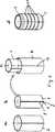
図1は、この発明に従った二重壁のハウジングを有する排気ガス用触媒反応装置を長さ方向の断面図で示す。
図2a〜2dは、そのようなハウジングの製造過程を概略的に示す。
図1は、触媒担体3を含む排気ガス用触媒反応装置に関するこの発明の原理を示す。触媒担体3は、メタルシート等で作られるハニカム状の本体であって、内側のジャケット1によって封入される。内側のジャケット1の両端部は、金属の触媒担体3から突き出している。内側のジャケット1は外側のジャケット2によって同心円状に取り囲まれる。外側のジャケット2は内側のジャケット1と等しい長さを有する。外側のジャケット2の外側の端部領域4、5は、内側のジャケット1に向かって変形されて、内側のジャケット1上に位置し、内側のジャケットを圧縮歪下におく。図1から理解されるように、ジャケット1、2はその後の設置される状態において、互いに接合されかつ排気システムの排気管9に接合される。これらの接続は溶接によって行なわれる。図1の右側における、さらなる排気管との対応する接続は図示されていない。
内側のジャケット1と外側のジャケット2との間には、環状の間隙10が形成され、これはとりわけ断熱の役割を果たす。外側のジャケットチューブにはエンボス加工された特徴が備えられるが、この特徴は好ましくはそのまわり全体に形成されて、ハウジングの長さにわたって均一に配分される。エンボス加工された特徴11は内側のジャケット1の方に向かう。示される実施例においては、エンボス加工された特徴11は内側のジャケットチューブ1に接触せず、そのため内側および外側のジャケット間に付加的な熱の連絡路が作られることはない。エンボス加工された特徴は、必要に応じて、内側のジャケット1に接触するように実現されることも可能である。内側のジャケットチューブ上に接触するエンボス加工特徴および接触しないエンボス加工特徴を混合して配することもまた可能である。加えて、断熱層を間隙10内に配置することも可能である。二重壁のハウジングは、その空間的な設計により、強い機械的安定性を有する。特に、エンボス加工された特徴がハウジングに半径方向の変形に対する強い抵抗を与える。このため、内側および外側のジャケットの壁の厚さが各々約0.5mmであり間隙のサイズが0.3mmから2mmであるハウジングに、約1.5mmの壁の厚さを有する単一の壁のハウジングの安定性が与えられ、しかも、このハウジングは、重量はより軽く、より良い断熱特性を有する。
図1に示されるハウジングは、図2に関連して下に記載されるように製造され得るが、これは単に一実施例にすぎない。他の製造プロセスも可能であり、特に、円錐形の本体も同様に製造され得る。円錐形の本体は、コールドスタートまたは再スタートにおける熱損失を減じるので、触媒反応装置の入口または出口の円錐として有利である。
実質的に長方形のメタルシートが巻かれて円筒形のジャケット2が形成される。このジャケットの境を接する縁部は、13において互いに溶接される。別のメタルシートが実質的に円筒に巻かれて、内側のジャケット1が形成される。図2に示されるように、内側のジャケットは対向する縁部6、7によって規定される分割線8を有する。
このようにして作られたジャケット1、2は、一方がその他方の内部へと押し込まれるが、中間に断熱層12を選択的に有する。好ましくは、内側のジャケットはその分割線が溶接シームの真上に位置することのないように配される。
一方が他方の内部に挿入されたジャケットは、その後、端部領域で変形されることが好ましく、それによりハウジングの断面が触媒担体の外側の断面と実質的に等しくなる。このプロセスにおいて外側のジャケット2は円周に対して塑性変形され、それにより外側のジャケットは内側のジャケット1に接触して、内側のジャケットを圧縮歪下に保ち、少なくとも内側のジャケットの弾性変形を引き起こす。エンボス加工された特徴11は予めまたは同時に外側のジャケット2上に形成され得る。図1および図2に示されるように、エンボス加工特徴は好ましくは、ジャケット2の円周上に形成される、取囲むビードである。これらのエンボス加工特徴はハウジングの長さにわたってほぼ均一に配分されるべきである。取囲むビードは、ふいごがそうであるように、内側のジャケット1と外側のジャケット2との間の熱歪を補償するために、長さ方向のある程度の弾性をハウジングに与える。しかし、このような効果が望まれない場合には、外側のジャケットに所望のすべての方向に対して付加的な安定性を与える、他の種類のエンボス加工特徴が備えられ得る。外側のジャケット2および内側のジャケット1はまた、全体的な特性を最適化するために、フェライトおよびオーステナイト等の、様々な材料で構成されてもよい。
熱伝導特性に意図的に影響を与えるために、内側のジャケット1の外側および/または外側のジャケット2の内側に、コーティングを付加的に備えることも可能である。排気ガス用触媒反応装置内で生じる温度下で、放熱は既に重要な役割を果たしているが、コーティングは放熱による熱伝達を減じる。この点を考慮に入れて、酸化膜または反射層が特に好適である。
この発明は、特に厳しい環境保護規制に応じなくてはならない、自動車内の排気ガス用触媒反応装置に特に好適である。なぜなら、コールドスタートおよびウォームスタートでの点火性能を改善することが可能なためである。The invention relates in particular to a double-walled housing for an automotive exhaust catalytic reactor comprising a metal catalyst support through which exhaust gas can flow.
Many forms of catalyst support are known. An example of a metal catalyst support can be found in EP-A 0 245 737. The catalyst body can be constructed from, for example, a metal sheet or can be manufactured by powder metallurgy.
Such a catalyst carrier is arranged in the housing. In such bodies, mechanical strains are generated by changing thermal stresses, so there is a suggestion on how to properly reduce such strains or in particular by embodying an exterior. It has already been done.
European Patent Publication EP-B 0 435 956 discloses a double-walled housing for exhaust catalytic reactors, especially for automobiles. The honeycomb-shaped catalyst carrier is supported by an inner jacket tube disposed in the outer jacket tube. The inner jacket tube is disposed in the outer jacket tube so as to be lengthwise extendable. The extension in the length direction is possible due to the sliding fit.
German utility model DE-U 74 01 002 discloses a housing with an inner jacket and an outer jacket for the catalyst support body. The housing houses a ceramic catalyst carrier. A compressible porous vibration damping layer is disposed between the inner jacket and the catalyst support. In order to comply with increasingly stringent environmental laws, the cold start and restart characteristics of exhaust gas catalytic reactors are becoming increasingly important. Since the thermal insulation properties of the housing play an important role with respect to these properties, it is required to improve them while maintaining the current manufacturing economy.
The object of the present invention is therefore to produce a double-walled housing that can be manufactured easily and economically, has strong stability and favorable thermal insulation properties, in particular as an exterior for catalytic reactors. . This housing must also be suitable for other parts of the exhaust system, for example conical parts, especially in view of its thermal insulation properties.
This object is achieved by a double-walled housing having the characteristics of claim 1 and by a method for its manufacture as defined in claim 17. Advantageous features are described in various dependent claims and are described in more detail in connection with the embodiments shown in the accompanying drawings.
A double wall housing, particularly for an automobile exhaust gas catalytic reactor, has an inner jacket and an outer jacket that is spaced from and substantially concentrically surrounds the inner jacket. Here, the inner jacket and the outer jacket are in close contact with each other at both ends of the surface. The inner jacket is kept under compressive strain by tightening the outer jacket, at least in the region of both ends, and the outer jacket is provided with embossed features towards the inner jacket. This embossed feature is preferably disposed substantially uniformly over the length and circumference of the housing to provide uniform mechanical stability.
The jacket may include a metal sheet, but its total wall thickness is less than the wall thickness of a single housing known previously. In order to give the housing a sufficiently strong stability, the outer jacket is provided with embossed features directed towards the inner jacket, which are preferably formed symmetrically on the outer jacket. These embossed features are preferably implemented such that they provide the housing with strong stability in both radial and tangential directions. By this means and due to the insulating gap formed between the two jackets, the inner jacket tube can be heated faster with the catalyst support and is overall higher than without the outer jacket. The temperature can be reached. This characteristic reduces the thermal stress inside the catalyst support. In addition, the inner jacket is not exposed to any external influences, allowing the material to be selected from a wider range. These properties of the housing also allow the wall thickness of the inner jacket to be reduced.
The thermal insulation properties of the housing can be achieved by contacting some of the embossed features of the outer jacket with the inner jacket, or by providing an additional thermal insulation layer or coating on or between the two jackets. Can be adjusted intentionally. In addition to the heat conduction best reduced by the air gap between the two jackets, the thermal convection best prevented by the ceramic interlayer also plays a role. However, another important factor at higher temperatures is thermal radiation. This can be reduced or reflected by a suitable coating. The housing according to the invention makes it possible to intentionally adapt these properties to the requirements imposed on them, especially in catalytic reactors. As a result, the cold start and restart characteristics of such catalytic reactors can be improved.
In accordance with the present invention, the outer tube includes a preferably rolled metal sheet shaped into a cylinder or cone, and the bordering edges are joined together by a joining technique. The expression “wound in a cylinder” should be understood to mean other than a shape having a circular cross section. Thus, for example, an oval or oval shape may be included.
In a further advantageous concept, the inner jacket comprises a metal sheet wound in a cylinder with a parting line extending over the entire length of the jacket. This feature has the advantage of simplifying manufacturing. This is because the inner jacket is not closed in its circumferential direction and therefore requires one less seam.
A method for manufacturing a double-walled housing according to the present invention includes the following steps:
The inner jacket is formed by deforming, preferably winding, the metal sheet into a cylindrical or conical shape, where the dividing line is maintained,
The outer jacket is formed by deforming the metal sheet into a cylindrical or conical shape, preferably winding and connecting the edges abutted against each other with a joining technique;
-The inner jacket is placed in the outer jacket;
The outer jacket is plastically deformed inward over its entire circumference at both ends of the surface, so that the inner jacket is kept under compressive strain. The outer jacket is provided with an embossed feature directed towards the inner jacket in advance or simultaneously. Prior to deformation of the outer jacket, a thermal insulation layer may be disposed between the inner jacket and the outer jacket.
An inner jacket tube may be provided on the outer side of the inner jacket and / or an outer jacket tube may be provided on the inner side of the outer jacket. These tubes are coated with, for example, an oxide film, which affects the heat dissipation characteristics. In a subsequent installation operation, the ends of the inner jacket tube and outer jacket tube surfaces may be welded together before or during joining to adjacent components.
Further advantages and features of the present invention will now be described with respect to a preferred embodiment, namely an exhaust gas catalytic reactor.
FIG. 1 shows a longitudinal cross-sectional view of an exhaust gas catalytic reactor having a double-walled housing according to the present invention.
2a to 2d schematically show the manufacturing process of such a housing.
FIG. 1 shows the principle of the present invention relating to an exhaust gas catalytic reactor including a
An
The housing shown in FIG. 1 may be manufactured as described below in connection with FIG. 2, but this is merely one example. Other manufacturing processes are possible, in particular a conical body can be manufactured as well. The conical body is advantageous as an inlet or outlet cone of the catalytic reactor because it reduces heat loss during cold start or restart.
A substantially rectangular metal sheet is wound to form a
One of the
The jacket with one inserted inside the other is then preferably deformed in the end region, so that the cross section of the housing is substantially equal to the cross section of the outside of the catalyst support. In this process, the
It is also possible to additionally provide a coating on the outside of the inner jacket 1 and / or the inside of the
The present invention is particularly suitable for an exhaust gas catalytic reaction apparatus in an automobile, which must comply with particularly strict environmental protection regulations. This is because the ignition performance at cold start and warm start can be improved.
Claims (20)
Translated fromJapaneseApplications Claiming Priority (3)
| Application Number | Priority Date | Filing Date | Title |
|---|---|---|---|
| DE4445557.7 | 1994-12-20 | ||
| DE4445557ADE4445557A1 (en) | 1994-12-20 | 1994-12-20 | Double-walled housing, especially for exhaust gas catalysts of motor vehicles |
| PCT/EP1995/004585WO1996019647A1 (en) | 1994-12-20 | 1995-11-21 | Double-walled housing, especially for catalytic converters in motor vehicles |
Publications (2)
| Publication Number | Publication Date |
|---|---|
| JPH10510899A JPH10510899A (en) | 1998-10-20 |
| JP3836136B2true JP3836136B2 (en) | 2006-10-18 |
Family
ID=6536435
Family Applications (1)
| Application Number | Title | Priority Date | Filing Date |
|---|---|---|---|
| JP51945096AExpired - Fee RelatedJP3836136B2 (en) | 1994-12-20 | 1995-11-21 | Double-wall housing, especially for automotive exhaust catalytic reactor |
Country Status (11)
| Country | Link |
|---|---|
| US (1) | US6334981B1 (en) |
| EP (1) | EP0799369B1 (en) |
| JP (1) | JP3836136B2 (en) |
| KR (1) | KR100371015B1 (en) |
| CN (1) | CN1086771C (en) |
| AU (1) | AU3983895A (en) |
| DE (2) | DE4445557A1 (en) |
| ES (1) | ES2118639T3 (en) |
| MY (1) | MY123004A (en) |
| TW (1) | TW329455B (en) |
| WO (1) | WO1996019647A1 (en) |
Families Citing this family (36)
| Publication number | Priority date | Publication date | Assignee | Title |
|---|---|---|---|---|
| DE19755126B4 (en)* | 1996-12-27 | 2007-07-19 | Emitec Gesellschaft Für Emissionstechnologie Mbh | Catalyst arrangement with two-branch exhaust system |
| DE19755703B4 (en)* | 1997-12-15 | 2008-03-13 | Emitec Gesellschaft Für Emissionstechnologie Mbh | Catalyst support arrangement for installation close to the engine |
| KR100517786B1 (en) | 1997-09-03 | 2005-09-30 | 에미텍 게젤샤프트 퓌어 에미시온스테크놀로기 엠베하 | Catalyst support assembly to be mounted in an engine compartment |
| DE19819202A1 (en)* | 1998-04-29 | 1999-11-04 | Emitec Emissionstechnologie | Conical honeycomb body and process for its manufacture |
| DE19820433A1 (en) | 1998-05-07 | 1999-11-11 | Emitec Emissionstechnologie | Support structure with a deformation element with oblique force transmission |
| DE19820463A1 (en) | 1998-05-07 | 1999-11-11 | Emitec Emissionstechnologie | Support structure with a deformation element with radial deformation limiters |
| DE19820449A1 (en) | 1998-05-07 | 1999-11-11 | Emitec Emissionstechnologie | Support structure with a deformation element with a shortened remaining block length |
| SE522537C2 (en)* | 2000-03-21 | 2004-02-17 | Kemira Metalkat Oy | Catalyst support with jacket |
| JP2003200060A (en)* | 2002-01-10 | 2003-07-15 | Calsonic Kansei Corp | Metal-made catalyst carrier and manufacturing method therefor |
| US7032312B2 (en)* | 2002-07-16 | 2006-04-25 | Calsonickansei North America, Inc. | Catalytic converter and method for manufacture thereof |
| US7238327B2 (en)* | 2002-12-10 | 2007-07-03 | Automotive Components Holdings, Llc | Method of attaching internal heat shield in automotive catalytic converters |
| US20040221305A1 (en)* | 2003-04-30 | 2004-11-04 | International Business Machines Corporation | Apparatus, method and computer programming product for cable TV service portability |
| DE102004058268B4 (en)* | 2003-12-11 | 2016-05-19 | Continental Automotive Gmbh | Reinforced housing of an exhaust gas purification component |
| US20050207948A1 (en)* | 2004-03-17 | 2005-09-22 | Hans Borneby | Catalytic converter with integral heat shield device |
| DE102004037480A1 (en)* | 2004-08-03 | 2006-03-02 | Zeuna-Stärker GmbH & Co KG | A vehicle exhaust gas purification device and method of manufacturing the same |
| US7740105B2 (en)* | 2004-10-28 | 2010-06-22 | Sango Co., Ltd. | Outer tube of exhaust system part |
| DE102005017946B4 (en) | 2005-04-18 | 2007-11-22 | J. Eberspächer GmbH & Co. KG | Exhaust treatment device and associated exhaust system |
| DE102005017947A1 (en)* | 2005-04-18 | 2006-10-19 | J. Eberspächer GmbH & Co. KG | Exhaust treatment device for an exhaust system |
| DE102005046767A1 (en)* | 2005-09-29 | 2007-04-05 | Arvinmeritor Emissions Technologies Gmbh | Method for producing a calibrated component, in particular for an exhaust system of a motor vehicle, and component for an exhaust system |
| DE102005048909A1 (en)* | 2005-10-10 | 2007-04-12 | J. Eberspächer GmbH & Co. KG | Component of an exhaust system |
| US7765801B2 (en)* | 2005-11-30 | 2010-08-03 | Benteler Automotive Corporation | Exhaust gas treatment device with insulated housing construction |
| US20070243116A1 (en)* | 2006-04-13 | 2007-10-18 | Klaus Mueller-Haas | Metallic substrate system |
| US7611561B2 (en)* | 2006-07-20 | 2009-11-03 | Benteler Automotive Corporation | Diesel exhaust filter construction |
| DE102008046527B4 (en)* | 2008-09-10 | 2021-09-16 | Faurecia Emissions Control Technologies, Germany Gmbh | Method for producing a device carrying exhaust gas and a tool therefor |
| JP5146777B2 (en)* | 2009-03-11 | 2013-02-20 | 本田技研工業株式会社 | Catalyst holding structure |
| DE102009018823A1 (en)* | 2009-04-24 | 2010-11-04 | J. Eberspächer GmbH & Co. KG | Housing for an exhaust treatment device and manufacturing method |
| DE102011016170A1 (en)* | 2011-04-05 | 2012-10-11 | Faurecia Emissions Control Technologies, Germany Gmbh | Exhaust gas device and method for its production |
| CN102619593A (en)* | 2012-04-27 | 2012-08-01 | 郭文慧 | Automobile exhaust cleaning tube |
| DE102012219120A1 (en)* | 2012-10-19 | 2014-04-24 | Robert Bosch Gmbh | Thin-walled housing with cooling fluid directing power transmission elements |
| DE102014010857A1 (en)* | 2014-07-25 | 2016-01-28 | Man Diesel & Turbo Se | Catalyst unit, method for producing the same and exhaust gas catalyst |
| WO2016119865A1 (en)* | 2015-01-29 | 2016-08-04 | Faurecia Emissions Control Technologies, Germany Gmbh | Method for producing a cylindrical housing of an exhaust system and a method for producing an exhaust treatment unit |
| DE112016002115T5 (en)* | 2015-06-30 | 2018-03-08 | Cummins Emission Solutions Inc. | Bead-shaped outer body for mounting and connection interfaces |
| US10005117B2 (en)* | 2015-10-20 | 2018-06-26 | Admc Holding, Llc | End cap seaming apparatus and method for seaming an end cap |
| CN106481413A (en)* | 2016-12-14 | 2017-03-08 | 姜学杰 | A kind of new tail gas catalyzing unit |
| CN111022168B (en)* | 2019-12-27 | 2020-12-25 | 东风汽车集团有限公司 | Oxygen sensor heat insulation protection device |
| DE102022212757A1 (en)* | 2022-11-29 | 2024-05-29 | Emitec Technologies GmbH | Device for the aftertreatment of exhaust gases |
Family Cites Families (11)
| Publication number | Priority date | Publication date | Assignee | Title |
|---|---|---|---|---|
| GB1391509A (en)* | 1971-08-25 | 1975-04-23 | Ford Motor Co | Method for decreasing nitrogen oxides in exhaust gases |
| US3841839A (en)* | 1972-11-17 | 1974-10-15 | Corning Glass Works | Catalytic converter |
| DE2856030C2 (en)* | 1978-12-23 | 1987-02-12 | Süddeutsche Kühlerfabrik Julius Fr. Behr GmbH & Co KG, 7000 Stuttgart | Method for producing a carrier matrix wound from metal foils for an exhaust gas cartridge |
| US4343074A (en)* | 1979-10-22 | 1982-08-10 | Uop Inc. | Method of making a catalytic converter |
| JPH07116933B2 (en)* | 1986-05-31 | 1995-12-18 | カルソニック株式会社 | Metal catalytic converter |
| DE3733402A1 (en)* | 1987-10-02 | 1989-04-13 | Emitec Emissionstechnologie | CATALYST ARRANGEMENT WITH FLOW GUIDE |
| DE8812762U1 (en)* | 1988-10-11 | 1989-06-29 | Emitec Gesellschaft für Emissionstechnologie mbH, 5204 Lohmar | Catalyst with double jacket system |
| DE3923517A1 (en)* | 1989-07-15 | 1991-01-24 | Porsche Ag | EXHAUST SYSTEM OF A PISTON PISTON ENGINE |
| DE4042266A1 (en)* | 1990-12-31 | 1992-07-02 | Eberspaecher J | DEVICE FOR TREATING COMBUSTION ENGINE EXHAUST GAS WITH TWO SPACED EXHAUST GAS TREATMENT BODIES |
| DE4112354A1 (en)* | 1991-04-16 | 1992-10-22 | Behr Gmbh & Co | DEVICE FOR CATALYTIC DETOXING OF EXHAUST GAS |
| US5293743A (en)* | 1992-05-21 | 1994-03-15 | Arvin Industries, Inc. | Low thermal capacitance exhaust processor |
- 1994
- 1994-12-20DEDE4445557Apatent/DE4445557A1/ennot_activeWithdrawn
- 1995
- 1995-11-03TWTW084111657Apatent/TW329455B/ennot_activeIP Right Cessation
- 1995-11-21EPEP95938458Apatent/EP0799369B1/ennot_activeExpired - Lifetime
- 1995-11-21JPJP51945096Apatent/JP3836136B2/ennot_activeExpired - Fee Related
- 1995-11-21AUAU39838/95Apatent/AU3983895A/ennot_activeAbandoned
- 1995-11-21DEDE59502441Tpatent/DE59502441D1/ennot_activeExpired - Lifetime
- 1995-11-21WOPCT/EP1995/004585patent/WO1996019647A1/enactiveIP Right Grant
- 1995-11-21CNCN95196916Apatent/CN1086771C/ennot_activeExpired - Fee Related
- 1995-11-21ESES95938458Tpatent/ES2118639T3/ennot_activeExpired - Lifetime
- 1995-11-21KRKR1019970703931Apatent/KR100371015B1/ennot_activeExpired - Lifetime
- 1995-12-11MYMYPI95003817Apatent/MY123004A/enunknown
- 1997
- 1997-06-20USUS08/879,594patent/US6334981B1/ennot_activeExpired - Lifetime
Also Published As
| Publication number | Publication date |
|---|---|
| DE59502441D1 (en) | 1998-07-09 |
| DE4445557A1 (en) | 1996-06-27 |
| EP0799369B1 (en) | 1998-06-03 |
| MY123004A (en) | 2006-05-31 |
| CN1086771C (en) | 2002-06-26 |
| JPH10510899A (en) | 1998-10-20 |
| TW329455B (en) | 1998-04-11 |
| EP0799369A1 (en) | 1997-10-08 |
| KR100371015B1 (en) | 2003-06-18 |
| ES2118639T3 (en) | 1998-09-16 |
| AU3983895A (en) | 1996-07-10 |
| CN1170451A (en) | 1998-01-14 |
| US6334981B1 (en) | 2002-01-01 |
| WO1996019647A1 (en) | 1996-06-27 |
Similar Documents
| Publication | Publication Date | Title |
|---|---|---|
| JP3836136B2 (en) | Double-wall housing, especially for automotive exhaust catalytic reactor | |
| US5293743A (en) | Low thermal capacitance exhaust processor | |
| US5787584A (en) | Catalytic converter | |
| US5380501A (en) | Exhaust gas cleaning device | |
| JP2957163B1 (en) | Exhaust system parts and manufacturing method | |
| US6185819B1 (en) | Catalytic converter housing arrangement | |
| EP1091101B1 (en) | Exhaust pipe assembly of two-passage construction | |
| US6673466B2 (en) | Housing with a passivation layer, catalyst carrier body with a housing and method for producing a catalyst carrier body with such a housing | |
| JP2001515168A (en) | Catalyst support arrangement for installation near the engine | |
| US4713361A (en) | Metallic catalyst body having thermal radiation protection | |
| US7258843B2 (en) | Assembly having a honeycomb body and a shortened, slit, inner casing tube | |
| US4948353A (en) | Metal catalyst carrier body having a shortened jacket tube and a method of producing the same | |
| JP4153565B2 (en) | Attached catalyst carrier provided with silencer casing and holding member, and method for producing the same | |
| US6156278A (en) | Catalytic converter configuration and exhaust gas system with a catalytic converter configuration | |
| US6274099B1 (en) | Device for catalytic conversion of exhaust gases in an exhaust system and process for manufacturing such a device | |
| JP4549607B2 (en) | Catalyst support with sleeve and shortened cylindrical jacket | |
| US6685888B1 (en) | Monolith supporting structure for use in catalytic converter | |
| JPH09151730A (en) | Exhaust double pipe | |
| EP1504817B1 (en) | Metal carrier for exhaust emission control | |
| US20010026780A1 (en) | Housing for an exhaust gas catalyst | |
| JP2578939Y2 (en) | Tandem metal carrier | |
| JPH10235205A (en) | Metal catalytic converter and method of manufacturing the same | |
| US20070243116A1 (en) | Metallic substrate system | |
| JP2529352Y2 (en) | 3-layer tube | |
| JPH1052626A (en) | Catalytic converter and exhaust gas purification device |
Legal Events
| Date | Code | Title | Description |
|---|---|---|---|
| A131 | Notification of reasons for refusal | Free format text:JAPANESE INTERMEDIATE CODE: A131 Effective date:20050215 | |
| A601 | Written request for extension of time | Free format text:JAPANESE INTERMEDIATE CODE: A601 Effective date:20050513 | |
| A602 | Written permission of extension of time | Free format text:JAPANESE INTERMEDIATE CODE: A602 Effective date:20050627 | |
| A521 | Request for written amendment filed | Free format text:JAPANESE INTERMEDIATE CODE: A523 Effective date:20050812 | |
| TRDD | Decision of grant or rejection written | ||
| A01 | Written decision to grant a patent or to grant a registration (utility model) | Free format text:JAPANESE INTERMEDIATE CODE: A01 Effective date:20060711 | |
| A61 | First payment of annual fees (during grant procedure) | Free format text:JAPANESE INTERMEDIATE CODE: A61 Effective date:20060726 | |
| R150 | Certificate of patent or registration of utility model | Free format text:JAPANESE INTERMEDIATE CODE: R150 | |
| FPAY | Renewal fee payment (event date is renewal date of database) | Free format text:PAYMENT UNTIL: 20090804 Year of fee payment:3 | |
| FPAY | Renewal fee payment (event date is renewal date of database) | Free format text:PAYMENT UNTIL: 20100804 Year of fee payment:4 | |
| FPAY | Renewal fee payment (event date is renewal date of database) | Free format text:PAYMENT UNTIL: 20110804 Year of fee payment:5 | |
| FPAY | Renewal fee payment (event date is renewal date of database) | Free format text:PAYMENT UNTIL: 20110804 Year of fee payment:5 | |
| FPAY | Renewal fee payment (event date is renewal date of database) | Free format text:PAYMENT UNTIL: 20120804 Year of fee payment:6 | |
| FPAY | Renewal fee payment (event date is renewal date of database) | Free format text:PAYMENT UNTIL: 20120804 Year of fee payment:6 | |
| FPAY | Renewal fee payment (event date is renewal date of database) | Free format text:PAYMENT UNTIL: 20130804 Year of fee payment:7 | |
| R250 | Receipt of annual fees | Free format text:JAPANESE INTERMEDIATE CODE: R250 | |
| R250 | Receipt of annual fees | Free format text:JAPANESE INTERMEDIATE CODE: R250 | |
| LAPS | Cancellation because of no payment of annual fees |