JP3835965B2 - Two-way communication system - Google Patents
Two-way communication systemDownload PDFInfo
- Publication number
- JP3835965B2 JP3835965B2JP2000017372AJP2000017372AJP3835965B2JP 3835965 B2JP3835965 B2JP 3835965B2JP 2000017372 AJP2000017372 AJP 2000017372AJP 2000017372 AJP2000017372 AJP 2000017372AJP 3835965 B2JP3835965 B2JP 3835965B2
- Authority
- JP
- Japan
- Prior art keywords
- signal
- slave station
- level
- master station
- station
- Prior art date
- Legal status (The legal status is an assumption and is not a legal conclusion. Google has not performed a legal analysis and makes no representation as to the accuracy of the status listed.)
- Expired - Fee Related
Links
- 230000006854communicationEffects0.000titleclaimsdescription124
- 238000004891communicationMethods0.000titleclaimsdescription124
- 230000005540biological transmissionEffects0.000claimsdescription111
- 238000011144upstream manufacturingMethods0.000claimsdescription72
- 230000002457bidirectional effectEffects0.000claimsdescription42
- 238000000034methodMethods0.000claimsdescription28
- 230000007175bidirectional communicationEffects0.000claimsdescription19
- 238000010586diagramMethods0.000description61
- 238000006243chemical reactionMethods0.000description14
- 230000003321amplificationEffects0.000description11
- 238000003199nucleic acid amplification methodMethods0.000description11
- 238000001514detection methodMethods0.000description7
- 230000002238attenuated effectEffects0.000description5
- 230000007274generation of a signal involved in cell-cell signalingEffects0.000description4
- 230000000644propagated effectEffects0.000description4
- 230000007812deficiencyEffects0.000description3
- 238000009434installationMethods0.000description3
- 230000002452interceptive effectEffects0.000description3
- 230000008054signal transmissionEffects0.000description3
- 230000032683agingEffects0.000description2
- 230000009291secondary effectEffects0.000description2
- 230000007423decreaseEffects0.000description1
- 230000000694effectsEffects0.000description1
- 239000000284extractSubstances0.000description1
- 230000012447hatchingEffects0.000description1
- 230000001771impaired effectEffects0.000description1
- 230000010355oscillationEffects0.000description1
- 238000011084recoveryMethods0.000description1
- 230000001360synchronised effectEffects0.000description1
- XOOUIPVCVHRTMJ-UHFFFAOYSA-Lzinc stearateChemical compound[Zn+2].CCCCCCCCCCCCCCCCCC([O-])=O.CCCCCCCCCCCCCCCCCC([O-])=OXOOUIPVCVHRTMJ-UHFFFAOYSA-L0.000description1
Images


Landscapes
- Two-Way Televisions, Distribution Of Moving Picture Or The Like (AREA)
Description
Translated fromJapanese【0001】
【発明の属する技術分野】
本発明は,例えば双方向CATV等,親局と1又は複数の子局との間で双方向のデータ通信を行う双方向通信システムに関するものである。
【0002】
【従来の技術】
CATV(Cable Television)は,元々テレビ電波の届きにくい難視聴地域にテレビ放送を配給することを目的としてサービスが開始されたため,従来のCATVは専ら単方向のTV配信サービスとして利用されてきた。しかしながら近年では,上記CATVのケーブル網を利用して双方向通信を実現し,各家庭に対して例えば高速なインターネット常時接続サービスや電話サービスを提供しようとする試みがなされ,注目されている(例えば特開平9−46667号公報)。
しかしながら,上記のような従来のCATV網を用いた双方向通信システムでは,全ての加入者宅までケーブルを敷設する必要があり,加入者の増加に伴って大きな投資が必要になる。また,種々の理由でケーブルの敷設が不可能,若しくは困難な場合も多い。例えば集合住宅などの場合には,各戸が連続して並んでいることから,実際にサービスを享受しない隣接戸などにも工事が必要な場合がある。このように,上記従来の双方向CATV通信システムでは加入者を増加させる上で大きな問題点があった。
そこで,家庭用端末に無線送受信機能を持たせ,ネットワークの末端部分を無線に置き換えた双方向無線CATVシステムが,例えば特開平10−13818号公報に提案されている。この双方向無線CATVシステムは,図17に示すように,家庭用端末101(子局),基地局102,ノード局104,及びこれらを一括して制御するヘッドエンド局103(親局)からなり,上記ヘッドエンド局103から上記ノード局104を介して上記基地局102までは従来通りケーブル接続され,上記基地局102と複数の家庭用端末101との間は10GHz帯以上の周波数を用いて無線で接続される。上記基地局102では,通信データの変復調,及び無線周波数との間の周波数変換が行われる。
これにより,新たにケーブルを敷設することが難しい地域などでも容易にサービスを提供することが可能となり,また,集合住宅などにも好適である。
【0003】
【発明が解決しようとする課題】
しかしながら,上記のような双方向無線CATVシステムでは,基地局から家庭用端末に至る構成が従来からのケーブル接続のみによる双方向CATVシステムと全く異なることから,例えば従来からのケーブル接続のみによる双方向CATVシステムを拡張して無線接続による加入者を共存させるようなシステムとすることは難しい。特に,家庭用端末として従来からのケーブル接続用の家庭用端末を用いることはできず,新たに無線送受信機能を持たせた家庭用端末を用いる必要があり,有線接続,無線接続それぞれの機器仕様が統一できないという問題点があった。また,末端以外の経路の一部を無線化したり,既存のCATV網の一部を無線に置き換えたりといったことには対応できない。
更に,上記双方向無線CATVシステムのように10GHz帯以上の無線周波数帯を用いた通信では,降雨減衰によって時には数十dB以上の大きな信号減衰が予想されるが,上記双方向無線CATVシステムではこれに対する特別の配慮がなされていないために,無線系の信号減衰量の変動によって復調特性が悪化する可能性があった。また,このような大きな信号減衰量の変化に対応できる特別のモデムを設計することも考えられるが,コスト高となってシステム全体のコストパフォーマンスを損なう恐れが生じる。
本発明は上記事情に鑑みてなされたものであり,その目的とするところは,従来のケーブル接続用の子局の基本仕様を変えることなくネットワークの一部を無線化することができ,更に,システム全体のコストパフォーマンスを損なうことなく無線系の信号減衰量の変動に対応することが可能な双方向通信システムを提供することである。
【0004】
【課題を解決するための手段】
上記目的を達成するために,本発明は,親局と1又は複数の子局との間で双方向のデータ通信を行う双方向通信システムにおいて,上記親局と上記子局とを結ぶケーブル経路上の任意箇所が,互いに無線で通信を行う1対の親局側無線通信手段と子局側無線通信手段とで接続され,上記親局側無線通信手段と上記子局側無線通信手段は,それぞれ,ケーブル側から受信した変調信号を所定の無線送信用周波数に変換して送出すると共に,相手側の無線通信手段から無線により受信した信号を所定のケーブル送信用周波数に変換してケーブル側に送出するように構成され,上記親局側無線通信手段が,高次の直交振幅変調信号である上記親局からの下り信号を復調するとともに,再度,より低次の直交振幅変調方式で変調する第1の復変調変換器を具備し,上記子局側無線通信手段が,上記より低次の直交振幅変調信号である上記親局からの下り信号を復調するとともに,再度,上記高次の直交振幅変調方式で変調する第2の復変調変換器を具備してなることを特徴とする双方向通信システムとして構成されている。
更に,上記親局側無線通信手段が,上記親局側からの信号のうち,当該親局側無線通信手段の下流側に接続されている子局に対する信号のみを選択的に上記子局側無線通信手段に送信するようにすれば,無線周波数が効率的に使用できる。また,無線の送信アンプの負荷も軽減できるため,より出力の小さな安価なシステムとすることが可能である。
また,上記親局から上記子局への下り信号を所定レベルに補正する下り信号レベル補正手段と,上記子局から上記親局への上り信号を上記下り信号レベル補正手段による補正量に基づいて補正する上り信号レベル補正手段とを,上記子局側無線通信手段若しくは上記子局に搭載すれば,親局に到達した時点での上り信号のレベルを,有線系,無線系での減衰変動に関わらず常に一定値とすることが可能である。
更に,上記下り信号レベル補正手段,及び上記上り信号レベル補正手段を上記親局側無線通信手段にも搭載すれば,子局に搭載される上記下り信号レベル補正手段及び上記上り信号レベル補正手段は無線系(親局側−子局側無線通信手段間)での動的な減衰変動のみを補正すればよく,比較的狭いダイナミックレンジで設計を行うことが可能となり,回路的な負荷が低減できる。
【0005】
一般にケーブル網内では下り方向に64値や256値の多値直交振幅変調が行いられているが,このような高次変調方式では高い信号対雑音比が要求される。しかしながら,10GHz以上の無線周波数帯を用いた通信では,伝搬距離に応じて大きな信号減衰を受ける可能性があるため,ケーブル網内の信号をそのまま周波数変換して10GHz無線周波数帯域で飛ばす場合には,この様な多値の変調方式を採用することは難しい。そこで,上記親局側無線通信手段に,高次(例えば64値や256値)の直交振幅変調信号を復調し,より低次(例えば4値や16値)の直交振幅変調方式で変調する上記第1の復変調変換器を搭載し,更に,上記子局側無線通信手段にも,低次(例えば4値や16値)の直交振幅変調信号を復調し,より高次(例えば64値や256値)の直交振幅変調方式で変調する上記第2の復変調変換器を搭載することが望ましい。
【0006】
また,上記子局から受信した信号レベルと所定の適正レベルとの比較に基づく信号レベル補正指令を上記子局に対して送信する補正指令送出手段を上記親局に搭載し,上記親局から受信した上記信号レベル補正指令に基づいて,上記親局へ送信する信号の送信レベルを補正する送信レベル制御手段を上記子局に搭載すれば,親局に到達したときの上り信号のレベルを所定の適正レベルに精度良く一致させることが可能となる。
また,上記子局側無線通信手段へ送信する信号と共に一定強度のパイロット信号を送出するパイロット信号発生手段を上記親局側無線通信手段に搭載し,上記親局側無線通信手段から受信した上記パイロット信号に基づいて上記親局側無線通信手段から受信した信号のレベルと上記子局側から受信した上り信号のレベルとを補正する信号補正手段を上記子局側無線通信手段に搭載して無線区間でのレベル変動を補正すれば,子局では,無線系(親局側−子局側無線通信手段間)で下り/上り信号が経験する動的変動の影響を受けずに有線系で発生するゲイン変動のみを補正すればよく,比較的少ないダイナミックレンジで設計をおこなうことができ,回路的な負荷が低減される。また,無線系を介して接続を行う場合に,有線系での接続を前提に設計された子局をそのまま用いることが可能となる。尚,当該双方向通信システムは,例えばケーブルテレビのネットワーク上に構築することが可能である。
【0007】
【作用】
本発明によれば,親局側−子局側無線通信手段間では無線送信用周波数に変換された上り/下り信号が送受信されるが,無線で受信した上り/下り信号は,上記無線送信用周波数への変換前の周波数に変換されてケーブル側に送出される。従って,上記子局側無線通信手段の配下にある子局は,ケーブルのみで接続されている子局と同様の構成とすることができる。更に,上記親局側/子局側無線通信手段は,各子局の直前に設置するだけでなく,ケーブル経路上の任意の箇所に設置することが可能であるため,通信網の構成の自由度が広がると共に,既存の有線系のみによる通信網を拡張することも容易である。このように,本発明によって,従来のケーブル接続用の子局の基本仕様を変えることなくネットワークの一部を無線化することが可能となる。
また,上記親局から上記子局への下り信号を所定レベルに補正する下り信号レベル補正手段と,上記子局から上記親局への上り信号を上記下り信号レベル補正手段による補正量に基づいて補正する上り信号レベル補正手段とを,上記子局側無線通信手段若しくは上記子局に搭載すれば,上り信号が親局に到達するまでに受けるであろう減衰量を予め子局において補正される。これにより,親局に到達した時点での上り信号のレベルを,有線系,無線系での減衰変動に関わらず常に一定値とすることが可能となる。
更に,上記下り信号レベル補正手段,及び上記上り信号レベル補正手段を上記親局側無線通信手段にも搭載すれば,無線系に送出されるときの送信レベルが一定に保たれる。これにより,子局に搭載される上記下り信号レベル補正手段及び上記上り信号レベル補正手段は無線系での動的な減衰変動のみを補正すればよく,比較的狭いダイナミックレンジで設計を行うことが可能となり,回路的な負荷が低減できる。
【0008】
また,上記親局側無線通信手段に,高次(例えば64値や256値)の直交振幅変調信号を復調し,より低次(例えば4値や16値)の直交振幅変調方式で変調する第1の復変調変換器を搭載し,ケーブル網内の高次の直交振幅変調信号を,無線周波数に変換する前に信号対雑音比の要求が緩い低次の直交振幅変調信号に変換するので,降雨等の大きな減衰を受ける無線区間において安定な通信が実現可能となる。
更に,上記子局側無線通信手段に,低次(例えば4値や16値)の直交振幅変調信号を復調し,より高次(例えば64値や256値)の直交振幅変調方式で変調する第2の復変調変換器を搭載するので,子局側の有線系では親局から送出された下り信号と同一の変調方式となるため,途中に変調方式の異なる無線区間が存在するか否かに関わらず,全て同じ構成の子局を用いることが可能である。
【0009】
また,上記子局から受信した信号レベルと所定の適正レベルとの比較に基づく信号レベル補正指令を上記子局に対して送信する補正指令送出手段を上記親局に搭載し,上記親局から受信した上記信号レベル補正指令に基づいて,上記親局へ送信する信号の送信レベルを補正する送信レベル制御手段を上記子局に搭載すれば,上記送信レベル制御手段による上り信号の送信レベル調整が繰り返され,親局における受信レベルが次第に適正レベルに収束する。これにより,親局に到達したときの上り信号のレベルを所定の適正レベルに精度良く一致させることが可能となる。
また,上記子局側無線通信手段へ送信する信号と共に一定強度のパイロット信号を送出するパイロット信号発生手段を上記親局側無線通信手段に搭載し,上記親局側無線通信手段から受信した上記パイロット信号に基づいて上記親局側無線通信手段から受信した信号のレベルと上記子局側から受信した上り信号のレベルとを補正する信号補正手段を上記子局側無線通信手段に搭載すれば,上記子局側無線通信手段の下流側での下り信号のレベルは上記親局側無線通信手段の上流側でのレベルと同一となる。従って,子局では無線系で下り/上り信号が経験する動的変動の影響を受けずに有線系で発生するゲイン変動のみを補正すればよく,比較的少ないダイナミックレンジで設計をおこなうことができ,回路的な負荷が低減される。また,無線系を介して接続を行う場合に,有線系での接続を前提に設計された子局をそのまま用いることが可能となる。
以上のように,システム全体のコストパフォーマンスを損なうことなく無線系の信号減衰量の変動に対応することが可能な双方向通信システムを提供することが可能となる。
【0010】
【発明の実施の形態】
以下,添付図面を参照して本発明の実施の形態につき説明し,本発明の理解に供する。尚,以下の実施の形態は,本発明を具体化した一例であって,本発明の技術的範囲を限定する性格のものではない。
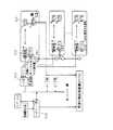
ここに,図1は本発明の実施の形態1に係る双方向CATVシステムA1の概略全体構成を示す図,図2は親局10の概略構成を示すブロック図,図3は無線中継基地局20の概略構成を示すブロック図,図4は無線中継子局40の概略構成を示すブロック図,図5は子局60の概略構成を示すブロック図,図6は上記双方向CATVシステムA1における無線系を介する親局−子局間での上り/下り信号の強度レベル変動の一例を示す図,図7は実施の形態2に係る双方向CATVシステムA2における無線系を介する親局−子局間での上り/下り信号の強度レベル変動の一例を示す図,図8はCATVヘッドエンド出口における同軸ケーブルC中の信号の周波数配置の一例を示す図,図9は実施の形態3に係る双方向CATVシステムA1′における無線系を介する親局−子局間での上り/下り信号の強度レベル変動の一例を示す図,図10は実施の形態4に係る双方向CATVシステムA2′における無線系を介する親局−子局間での上り/下り信号の強度レベル変動の一例を示す図,図11は実施の形態5に係る双方向CATVシステムA3における無線中継基地局20′の概略構成を示すブロック図,図12は同じく無線中継子局40′の概略構成を示すブロック図,図13は上記無線中継子局40′のパイロット信号レベル検出器53の周辺についての詳細ブロック図,図14はパイロット信号レベルpとdef(パイロット信号レベルpと参照レベルrefとの差)との関係,及び上記defと上記可変アッテネータの制御量(減衰量)の関係の一例を示す図,図15は上記双方向CATVシステムA3における無線系を介する親局−子局間での上り/下り信号の強度レベル変動の一例を示す図,図16は上記双方向CATVシステムA3におけるCATVヘッドエンド出口の同軸ケーブルC中の信号の周波数配置の一例を示す図である。
【0011】
(実施の形態1)
本実施の形態1に係る双方向CATVシステムA1は,請求項1〜4に係る双方向通信システムをCATV網に適用し,各加入者にアナログTV放送の他,高速のインターネット常時接続サービスを提供できるようにした一例であり,図1に示す如く,CATVヘッドエンド0と,各加入者宅に設置される複数の子局60a,60b(子局60で総称する)と,それらを結ぶ信号経路を構成する同軸ケーブルC(ケーブルの一例)と,該同軸ケーブルCの任意箇所を無線で接続する無線中継基地局20(親局側無線通信手段の一例)/無線中継子局40(子局側無線通信手段の一例)とを具備して構成されている。
【0012】
上記CATVヘッドエンド0は,アナログTV映像を配信するためのCATVアナログ映像配信システム1の他,双方向通信のための複数の親局10や各種サーバ,それらをインターネットに接続するルータ2が収容されている。上記CATVアナログ映像配信システム1と上記各親局10はその下流側で接続され,その接続点には合波器2が設置されている。
上記CATVヘッドエンド0の下流側出口からは,同軸ケーブル網がツリー状に敷設され,その端部にはTV受信機や子局60b,上記無線中継基地局20が接続されている。ここで,上記CATVヘッドエンド0と上記TV受信機や子局60bを結ぶケーブル網部分については,従来のケーブル接続のみによるCATV網の構成と基本的に共通である。
また,上記無線中継基地局20の下流側には,上記無線中継基地局20との間で無線通信を行う無線中継子局40が設置され,更に上記無線中継子局40の下流側には同軸ケーブルCによって子局60aが接続されている。即ち,上記無線中継基地局20から下流側は,既存のCATV網を拡張する形で設置されている。
上記子局60a,60bはそれぞれEthernetインターフェイスを搭載しており,1又は複数のパソコン等がネットワーク接続されている。尚,上記子局60aと60bは,親局10との間の信号経路上に無線系(無線中継基地局20−無線中継子局40)を介在しているか否かが異なるのみで,基本的構成は共通である。また,上記無線中継基地局20と上記無線中継子局40との関係,及び上記無線中継子局40と子局60aとの関係は,それぞれ1対1でも1対多でもよい。
【0013】
本システムA1の通信経路上では,上記CATVアナログ映像配信システム1からTV受信機へのアナログTV放送波と,上記親局10と上記子局60との間の双方向データ通信波との共存が可能である。上記双方向データ通信については,子局60から親局10方向の信号を伝送する上り信号と,親局10から子局60方向の下り信号とは別々の周波数を用いる周波数分割二重化方式(FDD)が用いられている。更に,上記下り信号は,時分割多重化方式(TDM)により異なる子局60への信号が多重化され,上記上り信号は,異なる子局60からの信号がバースト波による時分割多元接続(TDMA)により多重化される。上記CATVヘッドエンド0の下流側出口では,上記CATVアナログ映像配信システム1からのアナログTV放送波と,双方向データ通信用の上記上り/下り信号が重畳されており,その周波数配置は例えば図8のようになっている。
【0014】
続いて,図2〜図5に示す親局10,無線中継基地局20,無線中継子局40,及び子局60の概略構成ブロック図を参照しながら,各部の動作,及び通信の流れについて説明する。
まず,図2,図5を用いて,親局10と子局60との間の通信動作について説明する。
本システムA1では,加入者に対してインターネット常時接続サービスを提供している。そのため,図2,図5に示すように,親局10,子局60共にEthernetのインターフェイス回路11,66を備えている。
親局10において,上記インターフェイス回路11を介して取り込まれた各子局向け信号は,通信制御部12において時分割多重化方式によって多重化され,変調器13においてQPSK変調が施された後,自分(当該親局)の送信周波数として割り当てられた帯域に周波数変換され,周波数によって信号の流れ方向を制御するデバイスであるダイプレクサ14を介して下り信号として送出される。上記親局10からの下り信号は,他の親局10からの下り信号や上記CATVアナログ映像配信システム1からのアナログTV放送波と重畳されて同軸ケーブルCに送出される。
上記同軸ケーブルCや後述する無線中継系(無線中継基地局20と無線中継子局40)を介して子局60に到達した下り信号は,ダイプレクサ61を介して子局60内に取り込まれる。子局60では予め自分が通信を行う親局10に割り当てられている周波数帯域が分かっており,バンドパスフィルタ62によってその周波数帯域のみが取得される。続いて,上記下り信号は受信AGC回路63(下り信号レベル補正手段の一例)によって受信ゲインが一定レベルに補正された後,復調器64によってQPSK復調され,通信制御部65において再生される。得られたデータが,自分の配下に接続されている加入者機器宛のものであれば,上記インターフェイス回路66を介して上記加入者機器に送られる。
【0015】
一方,上記加入者機器からインターフェイス回路66を介して子局60内に取り込まれた上り信号は,まず通信制御部65に送られる。
ここで,上記上り信号はポーリング方式によって子局60から親局10に対して送信される。即ち,親局10がポーリングによって各子局60に対して上り方向のトラフィックを持っているか否かを尋ね,ある子局が上り方向のトラフィックを持っていればその子局がポーリングを受けたタイミングで上り信号を送出する。この時,各子局の送信クロックは親局のそれとは完全に同期が取れていないので,送出するフレームの先頭には同期用のプリアンブルが必要である。この時,各子局は親局から連続波として送信されている下り信号からクロック再生を行い,これを送信の際のクロックとして利用すれば,上記同期が容易となる。
このように,上記通信制御部65は上記親局10からのポーリングを待って上記上り信号を送出する。上記上り信号は,変調器67においてQPSK変調が施された後,送信GC回路68(上り信号レベル補正手段の一例)によって送信ゲインが補正される。この送信GC回路68によるゲイン補正には,上記受信AGC回路63によって行われた下り信号のゲイン補正量がそのまま用いられる(詳細は後述する)。上記送信GC回路68でゲイン補正された上り信号は,ダイプレクサ61を介して親局10に接続された同軸ケーブルCに送出される。
上記同軸ケーブルCや後述する無線中継系(無線中継基地局20と無線中継子局40)を介して親局10に到達した上り信号は,上記ダイプレクサ14を介して親局10内に取り込まれ,復調器15において復調された後,上記通信制御部12に送られて再生される。得られたデータは,必要に応じて上記インターフェイス回路11を介してインターネットに送出される。
【0016】
続いて,図3,図4を用いて,無線中継基地局20と無線中継子局40との間の無線中継系の動作説明を行う。
無線中継基地局20は,上記親局10と,有線CATVネットワーク(同軸ケーブルC)を介して接続されている。
上記同軸ケーブルCからダイプレクサ21を介して取り込まれた高調波側の下り信号(図8参照)は,バンドパスフィルタ22によって当該基地局20の配下に接続されている子局に無関係の信号が排除された後,受信AGC回路23(下り信号レベル補正手段の一例)によって受信ゲインが一定レベルに補正され,アップコンバータ24によって無線周波数に周波数変換される。この際,変換前の下り信号周波数と変換後の無線周波数はチャネルセレクタ32によって設定可能である。上記チャネルセレクタ32は周波数シンセサイザからなり,アップコンバータ24に供給する発振周波数を変更することで,信号を所望の無線周波数に変換することが可能である。無線周波数に周波数変換された下り信号は,パワーアンプ25によって電力増幅され,送信アンテナ26を介して空中に放射される。ここで,送信アンテナ26からは,当該基地局20の配下に接続されていない子局60に対する信号を送出しないため,無線周波数が効率的に使用できる。また,無線の送信アンプの負荷も軽減できるため,より出力の小さな安価なシステムとすることが可能である。尚,送信アンテナ26は,空間的に散らばって存在する複数の無線中継子局40に対して下り信号を送信するためにホーンアンテナを用いることが望ましい。
適度に広がりを持って送出された下り信号は,空間を伝搬して無線中継子局40の受信アンテナ41に到達する。無線中継子局40の受信アンテナ41は,対応する所定の無線中継基地局20からの送信波を受信するため,指向性の強いパラボラアンテナを用いることが望ましい。上記受信アンテナ41で受信された下り信号は,ローノイズアンプ42で必要な増幅を受けた後,ダウンコンバータ43で当該信号が同軸ケーブルC上を伝搬される場合に割り当てられた周波数帯域に周波数変換され,バンドパスフィルタ44,ダイプレクサ45を介して配下の子局60に接続された同軸ケーブルCに送出される。
【0017】
一方,配下の子局60からの上り信号は同軸ケーブルCから無線中継子局40に取り込まれ,ダイプレクサ45,バンドパスフィルタ46を介してアップコンバータ47によって無線周波数に周波数変換された後,パワーアンプ48によって電力増幅され,送信アンテナ49を介して空中に送出される。送信アンテナ49は,対応する所定の無線中継基地局20に対してのみ送信を行えばよいため,指向性の強いパラボラアンテナを用いることが望ましい。上記送信アンテナ49から送出された上り信号は,空間を伝搬して無線中継基地局20の受信アンテナ27に到達する。
無線中継基地局20の受信アンテナ27は,空間的に散らばって存在する複数の無線中継子局40からの上り信号を受信するためにホーンアンテナを用いることが望ましい。上記受信アンテナ27で受信された上り信号は,ローノイズアンプ28で一定の増幅を受けた後,ダウンコンバータ29で当該信号が同軸ケーブルC上を伝搬される場合に割り当てられた周波数帯域に周波数変換され,送信GC回路30(上り信号レベル補正手段の一例)によってゲイン補正される。この送信GC回路30によるゲイン補正には,上記受信AGC回路23で用いられた下り信号のゲイン補正量がそのまま用いられる(詳細は後述する)。上記送信GC回路30でゲイン補正された上り信号は,バンドパスフィルタ31,ダイプレクサ21を介して親局10に接続された同軸ケーブルCに送出される。
以上のように,上記無線中継基地局20と上記無線中継子局40との間では無線周波数に変換された上り/下り信号が送受信されるが,無線で受信した上り/下り信号は,上記無線周波数への変換前の周波数に変換されてケーブル側に送出されるため,上記無線中継子局40の配下にある子局60aは,ケーブルのみで接続されている子局60bと同様の構成とすることができる。更に,上記無線中継基地局20と上記無線中継子局40は,図1のように各子局60の直前に設置するだけでなく,CATV網の任意の箇所に設置することが可能である。これにより,CATV網の構成の自由度が広がると共に,既存の有線系のCATV網を拡張することも容易である。
また,上記無線中継基地局20と上記無線中継子局40は変復調機能を持たないために,その設備は極めて軽微なものにすることが可能である。また,これにより,自然環境の変化(雨,風,気温差等)に対する防護対策もまた軽微なものにすることが可能であり,コスト低減という副次的効果も得られる。
【0018】
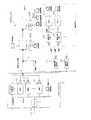
続いて,図6を用いて,本システムA1におけるゲイン調整について説明する。
図6の上半分には,図2〜図5に示した親局10,無線中継基地局20,無線中継子局40,及び子局60の構成ブロック図の中から,ゲイン調整に関与する要素を中心に以下の説明に必要な要素のみを抜き出して図示している。本図では,簡単のため,1つの無線中継基地局20を介して各1つの無線中継子局40及び子局60が有線系に接続された例を示しているが,無線中継基地局20が複数あっても,また無線中継子局40及び子局60が複数あっても説明の主旨に変わりはない。また,図6の下半分には,上半分のブロック図に対応する形で,下り信号及び上り信号のレベルダイヤグラムを図示している。尚,上記レベルダイヤグラムの縦軸は,その位置での信号強度を相対的に示したものであって絶対的な強度を示したものではない。
【0019】
図6を参照しながら,まず下り信号のゲイン調整の様子を説明する。
親局10から送信された下り信号は,同軸ケーブルCを伝搬して無線中継基地局20に至る。ここで,親局10からの送信出力は一定レベルである。これは,下り信号は数多くの子局によって受信されるため,親局側で各子局の個別の状況に合わせてゲイン調整をすることはできないからである。下り信号は,無線中継基地局20に至るまでの間に伝搬距離に応じた減衰を受ける(図6のレベルダイヤグラムに実線で示す)。ところが,無線中継基地局20に至る同軸ケーブルCは例えば数km以上といった長さであるため,この間の減衰量はケーブル特性の経年変化や,途中経路の分岐工事などによって変化する(一例を図6のレベルダイヤグラムに破線で示す)。
このような到達レベルの違いに関わらず,無線中継基地局20の受信AGC回路23では下り信号が一定レベルに調整される。受信AGC回路23によってゲイン補正を受けた下り信号は,周波数変換,パワーアンプ25による増幅を経て空中に放射される。尚,上記パワーアンプ25による増幅率は常に一定である。無線中継基地局20から放射された無線波はやがて無線中継子局40に至る。この無線伝搬時に下り信号は減衰を受けるが,その減衰量は天候等に大きく左右される。例えば10GHz帯以上の周波数では,晴天時には実線で示すような減衰であったものが,降雨時には雨粒による散乱で破線で示すようなより大きな減衰を受ける。このように,無線経路の環境により,無線中継子局40に到達する信号レベルは動的に変化する。
無線中継子局40に到達した下り信号は非常に微弱になっているので,ローノイズアンプ42による一定増幅率の増幅を受けて周波数変換され,子局60側に送出される。このように,無線中継子局40内では下り信号の到達レベルの差(図中の実線と破線のレベル差)はそのまま維持される。
子局60では,上記無線中継子局40から受信した下り信号が,受信AGC回路63によって再び一定レベルに調整され,復調器64に送られる。
以上のように,本システムA1では,無線中継基地局20に受信AGC回路23を搭載することにより無線系に送出されるときの送信レベルが一定に保たれるため,子局60に搭載される受信AGC回路63は無線系での動的な減衰変動のみを補正すればよく,比較的狭いダイナミックレンジで設計を行うことが可能となり,回路的な負荷が低減できる。無線区間の降雨減衰量変動は,場合によっては数十dBに達することがあり,これに加えて有線系での減衰量変動を補正する場合には,一箇所のAGC回路では非常に大きな制御ダイナミックレンジが必要になり,設計が困難になる。
また,無線中継基地局20,及び子局60における受信AGC回路(及び送信GC回路)の追従範囲を図6に斜線で示したが,無線中継基地局20及び子局60を設置した後の動的なゲイン変動がこの範囲に収まっていれば,残りの追従ダイナミックレンジはマージンとして残る。これは,このマージンの分は設置時の固定的な受信レベルがずれていても許容されるということを示しており,動的ゲイン変動に対する補正が無線中継基地局20と子局60に分散されて,マージンが増えれば設置時の調整もそれだけ容易になる。
【0020】
続いて,同様に上り信号のゲイン調整の様子を説明する。
上り信号は数多くの子局から親局に対して送信されるため,親局側で各子局からの個別の状況に合わせて上り信号のゲイン調整をすることはできない。そこで,上り信号は下り信号と同じ経路を通過して親局に至るということを利用して,下り信号のレベル変動分を上り信号のゲイン調整にフィードフォワードし,上り信号が親局に到達するまでに受けるであろう減衰量を予め子局において補正することにより,途中経路の減衰量変動の如何に関わらず親局に到達したときの上り信号のレベルが一定となるように制御する。即ち,まず子局60において,変調器67から一定レベルで送出された上り信号に対して,送信GC回路68によるゲイン補正が行われる。このときの補正量としては,上述した理由から上記受信AGC回路63による下り信号の補正量がそのまま用いられる。
例えば,子局60の受信AGC回路63における補正量が小さい場合には,無線区間の減衰が少なく比較的高レベルで下り信号が無線中継子局40に到達したことを意味している。従って,この場合には送信GC回路68において上記受信AGC回路63による補正量と同じ小さな補正量を用いることにより,上記無線区間を通過して無線中継基地局20に至る上り信号のレベルダイヤグラムは実線で示すようになる。逆に,下り信号の減衰が大きかった場合には,送信GC回路68において上記受信AGC回路63による補正量と同じ大きな補正量を用いることにより,上り信号のレベルダイヤグラムは破線で示すようになる。結果的に,低レベルで送出された場合には小さな減衰を受け,高レベルで送出された場合には大きな減衰を受けるため,無線中継基地局20に到達した時点の上り信号のレベルは常に一定値となる。
無線中継基地局20に到達した上り信号は,ローノイズアンプ28で増幅され,周波数変換を受けて送信GC回路30に至る。この送信GC回路30においても,上記子局60の送信GC回路68の場合と同様,有線系(親局10と無線中継基地局20との間のケーブル経路)で受けるであろう減衰量を予め補正するため,受信AGC回路23による下り信号の補正量がそのまま用いられる。これにより,親局10に到達した時点での上り信号のレベルは,有線系での減衰変動に関わらず常に一定値となる(図6の実線,破線のレベルダイアグラム参照)。
【0021】
以上説明したように,本実施の形態1に係る双方向CATVシステムA1では,上記無線中継基地局20と上記無線中継子局40との間では無線周波数に変換された上り/下り信号が送受信されるが,無線で受信した上り/下り信号は,上記無線周波数への変換前の周波数に変換されてケーブル側に送出されるため,上記無線中継子局40の配下にある子局60aは,ケーブルのみで接続されている子局60bと同様の構成とすることができる。更に,上記無線中継基地局20と上記無線中継子局40は,図1のように各子局60の直前に設置するだけでなく,CATV網の任意の箇所に設置することが可能である。これにより,CATV網の構成の自由度が広がると共に,既存の有線系のCATV網を拡張することも容易である。
また,上記無線中継基地局20と上記無線中継子局40は変復調機能を持たないために,その設備は極めて軽微なものにすることが可能である。また,これにより,自然環境の変化(雨,風,気温差等)に対する防護対策もまた軽微なものにすることが可能であり,コスト低減という副次的効果も得られる。
更に,無線中継基地局20においては,その配下に接続されていない子局60に対する信号は送出されないため,無線周波数が効率的に使用できる。また,無線の送信アンプの負荷も軽減できるため,より出力の小さな安価なシステムとすることが可能である。
また,無線中継基地局20に受信AGC回路23を搭載することにより,無線系に送出されるときの送信レベルが一定に保たれるため,子局60に搭載される受信AGC回路63は無線系での動的な減衰変動のみを補正すればよく,比較的狭いダイナミックレンジで設計を行うことが可能となって回路的な負荷が低減できる。また,これは上り信号に関する送信GC回路30,68についても同様のことがいえる。
更に,上記子局60における送信GC回路68,及び無線中継基地局20における送信GC回路30のゲイン補正量として,それぞれ受信AGC63,及び受信AGC23による下り信号のゲイン補正量がそのまま用いられるため,親局10に到達した時点での上り信号のレベルを,有線系,無線系での減衰変動に関わらず常に一定値とすることが可能である。
【0022】
尚,上記のように,下り側の受信AGC回路及び上り側の送信GC回路は,子局60と無線中継基地局20の両方に搭載することが理想であるが,無線中継基地局20側でそれらを省略したとしても本発明は成立する。
また,上記子局60に搭載されている受信AGC回路63,及び送信GC回路68は,無線系を介して接続されている子局60aにおいてはそれを省略し,代わりに同様の構成を上流側の無線中継子局40側に搭載することもできる。しかしながらこの場合には,有線系のみで接続されている子局60bと無線系を介して接続されている子局60aとで構成が異なってしまうことに注意が必要である。
【0023】
(実施の形態2)
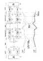
上記実施の形態1では,子局60及び無線中継子局40において下り信号の受信AGC回路の補正量を上り信号の送信GC回路の制御量として利用することで,親局10に到達した時点での上り信号のレベルを一定値とすることを可能にしている。しかしながら,この方法では親局10に到達した上り信号のレベルが完全に所定の適正レベルと一致している保証はなく,多少の誤差が生じる可能性もある。そこで,親局10に到達した上り信号のレベルと所定の適正レベルとの差に基づいて上記子局60の送信GC回路による上り信号のゲイン調整量を制御することも有効である(請求項1〜4を引用する請求項11に係る発明)。以下,図7を用いて本実施の形態2に係る双方向CATVシステムA2について説明する。尚,双方向CATVシステムA2を構成する親局10,無線中継基地局20,無線中継子局40,及び子局60の各構成図は図7で代用する。
図7は,図6と同様,上半分にゲイン調整に関与する要素を用いた構成ブロック図を,下半分に下り信号,及び上り信号のレベルダイヤグラムを図示したものである。尚,同図では,受信AGC回路,及び送信GC回路を,子局60ではなく無線中継子局40に搭載しているが,勿論上記実施の形態1と同様に子局60側に搭載してもよい。
【0024】
図7のレベルダイヤグラムのうち,実線は比較的通信経路の減衰量が小さい場合を,破線は減衰量が大きい場合をそれぞれ示している。通信経路の減衰量が比較的小さい場合においても,上記送信GC回路68′は,起動時点では図7に太線で示すようにある初期設定誤差を有している。この設定誤差は,無線系,有線系をそのまま伝搬し,最終的に親局10に到達する。途中,無線中継基地局20の送信GC回路30においてゲイン補正が行われるが,ここでの補正量は例えば受信AGC回路23における下り信号の補正量が用いられるため,上記送信GC回路68′の初期設定誤差分は補正されない。
親局10には,上り信号のレベルを検出する図示しないレベル検出回路が搭載されている。通信制御部12(補正指令送出手段の一例)では,上記レベル検出回路によるレベル検出値と所定の適正レベルとを比較し,上り信号レベルが上記適正レベルに対して高いか低いかの情報よりなる信号レベル補正指令を子局60に対する下り信号に含めて送信する。
子局60の通信制御部65(送信レベル制御手段の一例)では,下り信号から上記信号レベル補正指令を取り出し,これに基づいて送信GC回路68′を制御する。例えば,上り信号レベルが上記適正レベルに対して高すぎたのであれば次の送信では上記送信GC回路68′の補正量を少し低めに,低すぎたのであれば少し高めに制御する。この動作が,親局10における受信レベルが適正レベルとなるまで繰り返される。これにより,送信GC回路68′の誤差は次第に0に収束し,レベルダイヤグラムは太線から実線のように変化する。
また,天候が悪化した場合も,初期誤差の場合と同様,まず発生した誤差分が親局10で検出され,それに基づく信号レベル補正指令によって上記送信GC回路68′の調整を繰り返すことで次第に破線に示すような状態に収束する。
尚,上記親局10のレベル検出回路は,複数の子局からの受信バースト毎に動作し,信号レベル補正指令も各子局向けに発行されるため,ネットワークに複数の子局が接続されていても各子局をそれぞれ正しく制御することが可能である。更に,上記実施の形態1と上記実施の形態2を組み合わせて,無線中継子局40の送信GC回路68′の初期設定値として受信AGC回路63′における下り信号の補正量を用いるようにすることが望ましい。これにより,上記初期設定誤差を最小限に抑えることが可能となる。
【0025】
(実施の形態3)
一般に,ケーブル網内では下り方向に64値や256値の多値直交振幅変調が行いられているが,このような高次変調方式では高い信号対雑音比が要求される。しかしながら,10GHz以上の無線周波数帯を用いた通信では,伝搬距離に応じて大きな信号減衰を受ける可能性があるため,ケーブル網内の信号をそのまま周波数変換して10GHz無線周波数帯域で飛ばす場合には,この様な多値の変調方式を採用することは難しい。この問題点を解決するためには,ケーブル網内の高次の直交振幅変調信号を,無線周波数に変換する前に低次の直交振幅変調信号に変換し,無線区間通過後,ケーブル網に出力される前に再び高次の直交振幅変調信号に変換するようにすればよい。
【0026】
降雨等の大きな減衰を受ける無線区間においては,より信号対雑音比の要求が緩い低次の変調方式を用いることで,安定な通信が実現可能である。例えば,親局−子局間の変調方式として64値の直交変調方式(以下,64QAMという)を用いている場合,10E−6のエラーレートで通信を行うためには,ビット当たりの信号電力対雑音電力密度の比で19dB程度必要である(斉藤洋一著,「ディジタル無線通信の変復調」,第125ページ,図4.16より)。これに対して,これを16値の直交変調方式(以下,16QAMという)に変換した場合,必要なビット当たりの信号電力対雑音電力密度比は14.2dBで済む(同上)。一方,同じ伝送レートの信号を16QAMで変調した場合,占有帯域幅は64QAMに比べて1.5倍拡大する。つまり,16QAMに変換した場合,同じ信号電力対雑音電力比を実現するためには1.5倍大きな出力が必要となる。以上を勘案して64QAMと16QAMとを比較すると,16QAMを用いた場合,(19dB−14.2dB)−10×log101.5=3dB低い出力で64QAMと同等の品質を得ることができることが分かる。16QAMを用いた場合,占有帯域幅が増加するが,無線周波数帯域に十分な帯域が確保されていれば問題にはならない。また,一般に多値変調になるほど,出力アンプの線形性や,変調に用いる局部発振器の位相ノイズなどへの性能要求も厳しくなるので,特に10GHz以上の高い周波数帯域の無線周波数を用いる場合には,無線区間においてより信号対雑音比の要求が緩い低次の変調方式を用いることの有効性は高い。
【0027】
以上のような考えに基づいて上記実施の形態1に係る双方向CATVシステムA1を改良した双方向CATVシステムA1′(請求項5〜10に係る発明を具現化した一例)を,図9を用いて説明する。尚,双方向CATVシステムA1′を構成する親局10,無線中継基地局20′,無線中継子局40′,及び子局60の各構成図は図9で代用する。図9は,図6と同様,上半分にゲイン調整に関与する要素を用いた構成ブロック図を,下半分に下り信号及び上り信号のレベルダイヤグラムを図示したものである。
【0028】
図9を参照しつつ,まず下り信号のゲイン調整の様子を説明する。
親局10の64QAM変調器13で変調された下り信号は,同軸ケーブルCよりなる有線系を介して無線中継基地局20′に到達する。無線中継基地局20′で受信された下り信号は,下り信号レベル補正手段としての受信AGC回路23により,復調のための適切な信号レベルに補正される。これにより,下り信号が有線系で受けた減衰が補正される。上記受信AGC回路23によりレベル補正された下り信号は,子局の復調器64と同様の構成を有する64QAM復調器35において復調される。この際,64QAM変調信号では変調信号1シンボル当たり6bitのディジタルデータが復元される。復調されたディジタルデータは,16QAM変調器36に入力される。16QAM変調器36では1シンボル当たり4bitのディジタルデータが送信可能であるから,親局10から受信したデータを過不足なく中継するために,16QAM変調器36のシンボルクロックとしては,64QAM復調器35のシンボルクロックの6/4(=1.5)倍のシンボルクロックが用いられる。これにより,64QAM復調器35で受信したデータを16QAM変調器36で過不足なく変調し,送信することができる。16QAM変調器36で再変調された下り信号は,周波数変換器24′で無線周波数に変換された後,パワーアンプ25を介して空中に送出される。尚,変調信号の占有帯域幅はシンボルレートに比例するので,16QAMの変調信号は親局10から送出された64QAMの変調信号に比べて帯域が1.5倍に広がっている。ここで,上記64QAM復調器35及び上記16QAM変調器36が第1の復変調変換器の一例である。
無線中継子局40′において受信された下り信号は,ローノイズアンプ42で必要な増幅を受けた後,周波数変換器43′で後の16QAM復調器56で用いられる中間周波数帯に変換される。続いて,下り信号レベル補正手段としての受信AGC回路55により,復調のための適切な信号レベルに補正される。これにより,下り信号が無線系で受けた減衰や降雨によるレベル変動が補正され,次の16QAM復調器56への入力レベルを一定に保つことが可能である。上記受信AGC回路55によりレベル補正された下り信号は,16QAM復調器56において復調され,1シンボル当たり4bitのディジタルデータが復元された後,更に続く64QAM変調器57で再変調される。ここで,64QAM変調では1シンボル当たり6bitの情報が伝送可能であるから,親局10から送信されたデータを過不足なく伝送するために,上記16QAM復調器56のシンボルクロックの4/6(=2/3)倍のシンボルクロックレートで変調される。ここで,上記16QAM復調器56及び上記64QAM変調器57が第2の復変調変換器の一例である。
このようにして再び親局送出時と同様の64QAM変調を受けた下り信号は,子局側の有線系を介して子局60に入力される。子局60には,子局側有線系での信号減衰を補正するための受信AGC回路63が備えられており,これによって受信信号レベルが適切なレベルに補正された後,64QAM復調器64で復調され,通信制御部65に入力される。
【0029】
以上説明したように,本実施の形態3に係る双方向CATVシステムA1′の下り信号には,降雨等の大きな減衰を受ける無線区間において,ケーブル網内に比べてより信号対雑音比の要求の緩い低次の変調方式(16QAM)を用いているため,安定な通信が実現可能である。
また,子局60で受信される下り信号は,親局から送出された下り信号と同一の変調方式(64QAM)が用いられているため,途中に変調方式の異なる無線区間が存在するか否かに関わらず,全て同じ構成の子局を用いることが可能である。
【0030】
続いて,同様に上り信号のゲイン調整の様子を説明する。この上り信号のゲイン調整については,基本的に上記実施の形態1に係る双方向CATVシステムA1とほぼ同じである。
子局60において,まず16QAM変調器67で変調された上り信号は,送信GC回路68において送信レベルの補正を受ける。上記送信GC回路68は,上記受信AGC回路63の補正信号に基づいて上り信号レベルを補正する。上記受信AGC回路63の補正信号は,子局側有線系での下り信号のレベル変動を反映したものであるため,予めこの補正信号で上り信号を補正しておくことで,無線中継基地局40′には上り信号が子局側有線系で受けるであろうレベル変動が補正された状態で到達する。これにより,子局側有線系での減衰変動を補正することができる。子局側有線系における下り信号の上記受信AGC回路63によるレベル補正と,上り信号の上記送信GC回路68によるレベル補正との関係は,図9下のレベルダイヤグラムのようになる。
子局側有線系を介して無線中継基地局40′に達した上り信号は,上り信号補正手段としての送信GC回路58によってレベル補正を受ける。上記送信GC回路58は,上記受信AGC回路55の補正信号に基づいて上り信号レベルを補正する。上記受信AGC回路55の補正信号は,無線系での下り信号のレベル変動を反映したものであるため,予めこの補正信号で上り信号を補正しておくことで,上り信号が無線系を伝搬する際に受けるであろう減衰変動を予め補正することができる。上記送信GC回路58によってレベル補正を受けた上り信号は,周波数変換器47で無線周波数に変換された後,パワーアンプ48で増幅され,空中に送出される。無線系における下り信号の上記受信AGC回路55によるレベル補正と,上り信号の上記送信GC回路58によるレベル補正との関係は,図9下のレベルダイヤグラムのようになる。
無線中継基地局20′で受信された上り信号は,周波数変換器29により親局側有線系で使用される上り信号周波数に周波数変換され,上り信号レベル補正手段としての送信GC回路30に入力される。上記送信GC回路30は,上記受信AGC回路23の補正信号に基づいて上り信号レベルを補正する。上記受信AGC回路23の補正信号は,親局側有線系での下り信号のレベル変動を反映したものであるため,予めこの補正信号で上り信号を補正しておくことで,親局10には上り信号が親局側有線系で受けるであろうレベル変動が補正された状態で到達する。これにより,親局側有線系での減衰変動を補正することができる。親局側有線系における下り信号の上記受信AGC回路23によるレベル補正と,上り信号の上記送信GC回路30によるレベル補正との関係は,図9下のレベルダイヤグラムのようになる。以上説明したような子局60から親局10に至る一連の送信GC回路でのレベル補正により,子局側有線系,無線系,親局側有線系の減衰変動によらず,上り信号は親局10に到達した時点で一定の適切なレベルに保たれる。適切なレベルで親局に入力した上り信号は,16QAM復調器15によって復調され,通信制御部12に入力される。
【0031】
尚,以上説明した実施の形態3に係る双方向CATVシステムA1′では,下り信号が無線中継基地局40′から子局側有線系を介して子局60に送信される例を示したが,子局60を無線中継基地局40′に直接接続することも可能である。この場合には無線中継基地局40′の16QAM復調器56と64QAM変調器57は必要なく,下り信号が16QAMのままで子局60に入力されるようにすればよい。但し,この場合の子局の構成は子局側有線系を介して接続される他の子局と異なってしまうことに注意が必要である。
また,上記の例では,ケーブル網内で64QAM,無線区間で16QAMを用いたが,これに限られるものではない。例えば,ケーブル網内で256QAM,無線区間で4QAMを用いるような構成も可能である。また,必ずしも直交振幅変調方式を用いる必要はなく,ケーブル網内と無線区間のいずれか若しくは両方に他の変調方式を用いることも可能である。
【0032】
(実施の形態4)
以上説明した実施の形態3についても,上記実施の形態2と同様,親局10に到達した上り信号のレベルと所定の適正レベルとの差に基づいて上記子局60の送信GC回路による上り信号のゲイン調整量を制御するような構成を追加することが有効である(請求項5〜10を引用する請求項11に係る発明)。以下,図10を用いて本実施の形態4に係る双方向CATVシステムA2′について説明するが,基本的な考え方は上記実施の形態2と全く同じである。
図10に示すように,双方向CATVシステムA2′では,下り信号と異なり,上り信号については子局60′から親局10′までの間で周波数変換と送信GC回路によるレベル補正を行っているだけであって,無線中継子局40′の送信GC回路58では無線区間で上り信号が受けるであろう減衰変動の補正が,無線中継基地局20′の送信GC回路30では親局側有線系で上り信号が受けるであろう減衰変動の補正が,それぞれ送信AGC回路55,23の補正信号に基づいて行われる。従って,図10下のレベルダイヤグラムに示すように,もし子局60′の送信GC回路68が初期設定誤差を有していた場合には,その誤差は子局側有線系,無線系,親局側有線系をそのまま伝搬し,最終的に親局10′に到達する。
親局10′には,上り信号のレベルを検出する図示しないレベル検出回路が搭載されている。通信制御部12′(補正指令送出手段の一例)では,上記レベル検出回路によるレベル検出値と所定の適正レベルとを比較し,上り信号レベルが上記適正レベルに対して高いか低いかの情報よりなる信号レベル補正指令を子局60′に対する下り信号に含めて送信する。子局60′の通信制御部65′(送信レベル制御手段の一例)では,下り信号から上記信号レベル補正指令を取り出し,これに基づいて送信GC回路68を制御する。例えば,上り信号レベルが上記適正レベルに対して高すぎたのであれば次の送信では上記送信GC回路68の補正量を少し低めに,低すぎたのであれば少し高めに制御する。この動作が,親局10′における受信レベルが適正レベルとなるまで繰り返される。これにより,送信GC回路68の誤差は次第に0に収束してレベルダイヤグラムは太線から実線のように変化し,上記送信GC回路68の初期設定誤差が補正される。
尚,初期設定誤差は,子局60′以外の無線中継子局40′や無線中継基地局20′で生じたものであっても,同様に親局10′まで伝搬するため,子局60′の送信GC回路68において同様に補正することが可能である。
【0033】
(実施の形態5)
続いて,請求項12に係る発明を具現化した一例を説明する。
本実施の形態5に係る双方向CATVシステムA3は,親局10,及び子局60の構成については図2,図5に示すものと同様である。
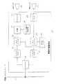
無線中継基地局20′(図11)は,図3に示す無線中継基地局20における受信AGC回路23及び送信GC回路30が省略され,合波器33及びパイロット信号発生回路34(パイロット信号発生手段の一例)が新たに搭載されている。
また,無線中継子局40′(図12)は,図4に示す無線中継子局40に,更にバンドパスフィルタ44′,パイロット信号レベル検出器53,受信GC回路51,及び送信GC回路52が新たに搭載されている。ここで,上記パイロット信号レベル検出器53,受信GC回路51,及び送信GC回路52が信号補正手段の一例である。
【0034】
以下,図11,図12を用いて,まず無線中継基地局20′と無線中継子局40′との間の無線中継系の動作を説明する。
無線中継基地局20′は,上記親局10と,有線CATVネットワーク(同軸ケーブルC)を介して接続されている。
上記同軸ケーブルCからダイプレクサ21を介して取り込まれた高調波側の下り信号は,バンドパスフィルタ22によって当該基地局20′の配下に接続されている子局に無関係の信号が排除された後,アップコンバータ24によって無線周波数に周波数変換される。この際,変換前の下り信号周波数と変換後の無線周波数はチャネルセレクタ32によって設定可能である。無線周波数に周波数変換された下り信号は,合波器33により,パイロット信号発生回路34で発生されたパイロット信号が加えられた後,パワーアンプ25によって電力増幅され,送信アンテナ26を介して空中に放射される。ここで,上記パイロット信号発生回路34では,下り信号とは異なる一定の周波数で一定出力の連続波が上記パイロット波として発振される。上記無線中継基地局20′の無線周波数側におけるアナログTV放送波,上り/下り変調波,及び上記パイロット信号の周波数配置の一例を図16に示す。
【0035】
適度に広がりを持った下り信号は,空間を伝搬して無線中継子局40′の受信アンテナ41に到達する。上記受信アンテナ41で受信された下り信号は,ローノイズアンプ42で必要な増幅を受けた後,ダウンコンバータ43で当該信号が同軸ケーブルC上を伝搬される場合に割り当てられた周波数帯域に周波数変換される。周波数変換された下り信号は2つに分岐され,その一方はバンドパスフィルタ44′において上記パイロット信号の周波数以外の変調波等が除去され,パイロット信号レベル検出器53に入力される。上記パイロット信号レベル検出器53では,入力されたパイロット信号の強度と所定の参照レベルとの差を演算し,これに基づいて,受信GC回路51のアッテネータの制御信号を発生する(図13に示す詳細ブロック図参照。尚,上記受信GC回路51へは,上記ダウンコンバータ43から出力された下り信号がバンドパスフィルタ44を介して入力される。)。例えば,検出されたパイロット信号の強度が上記参照レベルに対し1dB大きければ,可変アッテネータの減衰量を1dB増加させ,逆にパイロット信号の強度が上記参照レベルに対し1dB小さければ,可変アッテネータの減衰量を1dB減少させる。
図14に,パイロット信号レベルpとdef(パイロット信号レベルpと参照レベルrefとの差)との関係,及び上記defと上記可変アッテネータの制御量(減衰量)の関係の一例を示す。無線中継子局40′の初期設定は,降雨減衰のない晴天時に行う。晴天時には,受信GC回路51の可変アッテネータは小さい減衰量に設定し,これを通常時の動作点とする。尚,上記動作点は,降雨時に減衰量を十分に減少させて必要な受信レベルが得られるように適当な値に設定する必要がある。この調整は,参照レベルの調整によって可能である。図14に示すように,参照レベルを下げると動作点は高い側,即ち減衰量が大きい側に移動する。この調整以降,降雨により実際の受信レベルが低下してくると,動作点は図14の左方向に移動し,可変アッテネータの減衰量は小さくなり,結果として受信GC回路51を通過して子局60に至る下り信号は(有線系の減衰が一定であれば)設置時と同じレベルに維持されることになる。
上記受信GC回路51を通過した下り信号は,ダイプレクサ45を介して配下の子局60に接続された同軸ケーブルCに送出される。
【0036】
一方,配下の子局60からの上り信号は同軸ケーブルCから無線中継子局40′に取り込まれ,ダイプレクサ45を介して送信GC回路52に入力される。上記送信GC回路52では,上記受信GC回路51で用いられた調整量(上記パイロット信号レベル検出器53からの出力値)が用いられる。上記送信GC回路52から出力された上り信号は,バンドパスフィルタ46を介してアップコンバータ47によって無線周波数に周波数変換された後,パワーアンプ48によって電力増幅され,送信アンテナ49を介して空中に送出される。上記送信アンテナ49から送出された上り信号は,空間を伝搬して無線中継基地局20′の受信アンテナ27に到達する。
無線中継基地局20′の受信アンテナ27で受信された上り信号は,ローノイズアンプ28で必要な増幅を受けた後,ダウンコンバータ29で当該信号が同軸ケーブルC上を伝搬される場合に割り当てられた周波数帯域に周波数変換され,バンドパスフィルタ31,ダイプレクサ21を介して親局10に接続された同軸ケーブルCに送出される。
【0037】
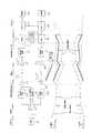
続いて,図15を用いて,本システムA3におけるゲイン調整について説明し,本実施の形態5の特徴点を明らかにする。
図15は,図6と同様,上半分にゲイン調整に関与する要素による構成ブロック図を,下半分に,上半分のブロック図に対応する形で,下り信号,及び上り信号のレベルダイヤグラムを図示したものである。尚,上記レベルダイヤグラムの縦軸はその位置での信号強度を相対的に示したものであって絶対的な強度を示したものではない。
【0038】
図15を参照しながら,まず下り信号のゲイン調整の様子を説明する。
親局10から送信された下り信号は,同軸ケーブルCを伝搬して無線中継基地局20′に至る。ここで,親局10からの送信出力は一定レベルである。下り信号は,無線中継基地局20′に至るまでの間に伝搬距離に応じた減衰を受ける(図15のレベルダイヤグラムに実線で示す)。ところが,無線中継基地局20′に至る同軸ケーブルCは例えば数km以上といった長さであるため,この間の減衰量はケーブル特性の経年変化や,途中経路の分岐工事などによって変化する(一例を図15のレベルダイヤグラムに破線で示す)。
ダイプレクサ21を介して無線中継基地局20′内に取り込まれた下り信号は,周波数変換を受けた後,パイロット信号発生器34で発生されたパイロット信号が加えられ,パワーアンプ25によって電力増幅された後,送信アンテナ26を介して空中に放射される。尚,上記パワーアンプ25による増幅率は常に一定である。
無線中継基地局20′から放射された無線波はやがて無線中継子局40′に至る。この無線伝搬時に下り信号は減衰を受けるが,その減衰量は天候等に大きく左右される。例えば10GHz帯以上の周波数では,晴天時には細線(実線:有線系での減衰小,破線:有線系での減衰大)で示すような減衰であったものが,降雨時には雨粒による散乱で太線(実線:有線系での減衰小,破線:有線系での減衰大)で示すようなより大きな減衰を受ける。このように,無線経路の環境により,無線中継子局40′に到達する信号レベルは動的に変化する。無線中継子局40′に到達した下り信号は,ローノイズアンプ42による一定増幅率の増幅を受けて周波数変換された後,先に説明したようにパイロット信号レベル検出器53からの出力値に基づいて受信GC回路52によるゲイン補正を受ける。これにより,下り信号の強度は上記無線中継基地局20′から無線送出される前のレベルに補正される。またこのとき,有線系での減衰量の差によるレベル差は補正されない(細実線と細破線との間のレベル差は変わらない)。即ち,子局60には親局10から無線中継子局40′への有線系で生じるゲイン変動がそのまま透過的に伝わることがわかる。従って,子局60における受信AGC回路63は無線系で下り信号が経験する動的変動の影響を受けずに有線系で発生したゲイン変動のみを補正すればよく,比較的少ないダイナミックレンジで設計をおこなうことができ,回路的な負荷が低減される。また,無線系を介して接続を行う場合でも,有線系での接続を前提に設計された子局をそのまま用いることが可能となる。
【0039】
続いて,同様に上り信号のゲイン調整の様子を説明する。
上記実施の形態1に係るシステムA1と同様,上り信号が親局に到達するまでに受けるであろう減衰量を予め子局において補正するため,まず子局60において,変調器67から一定レベルで送出された上り信号に対して,送信GC回路68によるゲイン補正が行われ,無線中継子局40′に送られる。このときの補正量としては,上述した理由から上記受信AGC回路63による下り信号の補正量がそのまま用いられる。この補正量は,子局60から親局10までの経路における有線系での減衰量に相当し,無線系の減衰量は含まない。
無線中継子局40′の送信GC回路51では,親局10までの経路における無線系での減衰量を予め補正するため,上記受信GC回路52による下り信号のレベル補正に用いられた補正量を用いて上り信号のレベル補正が行われる。その後,上り信号は無線周波数に周波数変換され,パワーアンプ48による一定の増幅を受けた後,無線送出される。
無線中継基地局20′に到達した上り信号は,ローノイズアンプ28で増幅され,周波数変換を受け,ダイプレクサ21を介して親局10側の同軸ケーブルCに送出される。この時点での上り信号は,上記無線中継子局40′の送信GC回路51でのゲイン補正分は使い果たされ,上記子局60の送信GC回路68による有線系を対象としたゲイン補正分のみが残っている。このゲイン補正分は有線系において失われ,上記上り信号は所定の適正レベルで親局10に到達する。
以上説明したように,本実施の形態5に係るシステムA3によれば,子局60における受信AG回路63及び送信GC回路68では,無線系で下り/上り信号が経験する動的変動の影響を受けずに有線系で発生するゲイン変動のみを補正すればよく,比較的少ないダイナミックレンジで設計をおこなうことができ,回路的な負荷が低減される。また,無線系を介して接続を行う場合でも,有線系での接続を前提に設計された子局をそのまま用いることが可能となる。
【0040】
更に,以上の実施の形態においては,上記無線中継系でアナログTV放送波を中継することも当然可能である。
また,親局−子局間の通信は,QPSK変調を用いたものに限られるものではなく,QAM方式などその他の変調方式を用いたものであっても本発明の本質は変わらない。また上り信号の送信方法についても,ポーリング方式に限られるものではなく,公知のSlotted ALOHA などの制御方式を用いることも可能である。更に,本発明はCATV網に限らず,他の双方向通信システムに適用することも可能である。
【0041】
【発明の効果】
以上説明したように,本発明は,親局と1又は複数の子局との間で双方向のデータ通信を行う双方向通信システムにおいて,上記親局と上記子局とを結ぶケーブル経路上の任意箇所が,互いに無線で通信を行う1対の親局側無線通信手段と子局側無線通信手段とで接続され,上記親局側無線通信手段と上記子局側無線通信手段は,それぞれ,ケーブル側から受信した変調信号を所定の無線送信用周波数に変換して送出すると共に,相手側の無線通信手段から無線により受信した信号を所定のケーブル送信用周波数に変換してケーブル側に送出するように構成されてなることを特徴とする双方向通信システムとして構成されているため,上記子局側無線通信手段の配下にある子局は,ケーブルのみで接続されている子局と同様の構成とすることができる。更に,上記親局側無線通信手段,子局側無線通信手段は,各子局の直前に設置するだけでなく,ケーブル経路上の任意の箇所に設置することが可能であるため,通信網の構成の自由度が広がると共に,既存の有線系のみによる通信網を拡張することも容易である。このように,本発明によって,従来のケーブル接続用の子局の基本仕様を変えることなくネットワークの一部を無線化することが可能となる。
さらに,上記親局側無線通信手段に,高次(例えば64値や256値)の直交振幅変調信号を復調し,より低次(例えば4値や16値)の直交振幅変調方式で変調する第1の復変調変換器を搭載するので,ケーブル網内の高次の直交振幅変調信号を,無線周波数に変換する前に低次の直交振幅変調信号に変換することができ,降雨等の大きな減衰を受ける無線区間において,より信号対雑音比の要求が緩い低次の変調方式を用いることで,安定な通信が実現可能である。
更に,上記子局側無線通信手段に,低次(例えば4値や16値)の直交振幅変調信号を復調し,より高次(例えば64値や256値)の直交振幅変調方式で変調する第2の復変調変換器を搭載するので,子局側の有線系では親局から送出された下り信号と同一の変調方式となるため,途中に変調方式の異なる無線区間が存在するか否かに関わらず,全て同じ構成の子局を用いることが可能である。
更に,上記親局側無線通信手段が,上記親局側からの信号のうち,当該親局側無線通信手段の下流側に接続されている子局に対する信号のみを選択的に上記子局側無線通信手段に送信するようにすれば,無線周波数が効率的に使用できる。また,無線の送信アンプの負荷も軽減できるため,より出力の小さな安価なシステムとすることが可能である。
また,上記親局から上記子局への下り信号を所定レベルに補正する下り信号レベル補正手段と,上記子局から上記親局への上り信号を上記下り信号レベル補正手段による補正量に基づいて補正する上り信号レベル補正手段とを,上記子局側無線通信手段若しくは上記子局に搭載すれば,親局に到達した時点での上り信号のレベルを,有線系,無線系での減衰変動に関わらず常に一定値とすることが可能である。
更に,上記下り信号レベル補正手段,及び上記上り信号レベル補正手段を上記親局側無線通信手段にも搭載すれば,子局に搭載される上記下り信号レベル補正手段及び上記上り信号レベル補正手段は無線系(親局側−子局側無線通信手段間)での動的な減衰変動のみを補正すればよく,比較的狭いダイナミックレンジで設計を行うことが可能となり,回路的な負荷が低減できる。
【0042】
また,上記子局から受信した信号レベルと所定の適正レベルとの比較に基づく信号レベル補正指令を上記子局に対して送信する補正指令送出手段を上記親局に搭載し,上記親局から受信した上記信号レベル補正指令に基づいて,上記親局へ送信する信号の送信レベルを補正する送信レベル制御手段を上記子局に搭載すれば,親局に到達したときの上り信号のレベルを所定の適正レベルに精度良く一致させることが可能となる。
また,上記子局側無線通信手段へ送信する信号と共に一定強度のパイロット信号を送出するパイロット信号発生手段を上記親局側無線通信手段に搭載し,上記親局側無線通信手段から受信した上記パイロット信号に基づいて上記親局側無線通信手段から受信した信号のレベルと上記子局側から受信した上り信号のレベルとを補正する信号補正手段を上記子局側無線通信手段に搭載すれば,子局では,無線系(親局側−子局側無線通信手段間)で下り/上り信号が経験する動的変動の影響を受けずに有線系で発生するゲイン変動のみを補正すればよく,比較的少ないダイナミックレンジで設計をおこなうことができ,回路的な負荷が低減される。また,無線系を介して接続を行う場合に,有線系での接続を前提に設計された子局をそのまま用いることが可能となる。
【図面の簡単な説明】
【図1】 本発明の実施の形態1に係る双方向CATVシステムA1の概略全体構成を示す図。
【図2】 親局10の概略構成を示すブロック図。
【図3】 無線中継基地局20の概略構成を示すブロック図。
【図4】 無線中継子局40の概略構成を示すブロック図。
【図5】 子局60の概略構成を示すブロック図。
【図6】 上記双方向CATVシステムA1における無線系を介する親局−子局間での上り/下り信号の強度レベル変動の一例を示す図。
【図7】 実施の形態2に係る双方向CATVシステムA2における無線系を介する親局−子局間での上り/下り信号の強度レベル変動の一例を示す図。
【図8】 CATVヘッドエンド出口における同軸ケーブルC中の信号の周波数配置の一例を示す図。
【図9】 実施の形態3に係る双方向CATVシステムA1′における無線系を介する親局−子局間での上り/下り信号の強度レベル変動の一例を示す図。
【図10】 実施の形態4に係る双方向CATVシステムA2′における無線系を介する親局−子局間での上り/下り信号の強度レベル変動の一例を示す図。
【図11】 実施の形態5に係る双方向CATVシステムA3における無線中継基地局20′の概略構成を示すブロック図。
【図12】 同じく無線中継子局40′の概略構成を示すブロック図。
【図13】 上記無線中継子局40′のパイロット信号レベル検出器53の周辺についての詳細ブロック図。
【図14】 パイロット信号レベルpとdef(パイロット信号レベルpと参照レベルrefとの差)との関係,及び上記defと上記可変アッテネータの制御量(減衰量)の関係の一例を示す図。
【図15】 上記双方向CATVシステムA3における無線系を介する親局−子局間での上り/下り信号の強度レベル変動の一例を示す図。
【図16】 上記双方向CATVシステムA3におけるCATVヘッドエンド出口の同軸ケーブルC中の信号の周波数配置の一例を示す図。
【図17】 従来の双方向無線CATVシステムの概略構成を示すブロック図。
【符号の説明】
A1,A2,A3…双方向CATVシステム
10…親局
12…通信制御部(補正指令送出手段の一例)
20,20′…無線中継基地局(親局側無線通信手段の一例)
22…バンドパスフィルタ
23…受信AGC回路(下り信号レベル補正手段の一例)
24…アップコンバータ
29…ダウンコンバータ
30…送信GC回路(上り信号レベル補正手段の一例)
34…パイロット信号発生回路(パイロット信号発生手段の一例)
35…64QAM復調器
36…16QAM変調器(35,36が第1の復変調変換器の一例)
40,40′…無線中継子局(子局側無線通信手段の一例)
43…ダウンコンバータ
47…アップコンバータ
51…受信GC回路
52…送信GC回路
53…パイロット信号レベル検出器(上記51,52と共に信号補正手段の一例を構成)
56…16QAM復調器
57…64QAM変調器(56,57が第2の復変調変換器の一例)
60(60a,60b)…子局
63,63′…受信AGC回路(下り信号レベル補正手段の一例)
65…通信制御部(送信レベル制御手段の一例)
68,68′…送信GC回路(上り信号レベル補正手段の一例)[0001]
BACKGROUND OF THE INVENTION
The present invention relates to a bidirectional communication system that performs bidirectional data communication between a master station and one or more slave stations, such as bidirectional CATV.
[0002]
[Prior art]
Since CATV (Cable Television) was originally started for the purpose of distributing television broadcasts to difficult viewing areas where television radio waves are difficult to reach, conventional CATV has been used exclusively as a one-way TV distribution service. In recent years, however, attempts have been made to realize bi-directional communication using the CATV cable network and to provide, for example, high-speed Internet always-on connection service and telephone service to each home (for example, JP-A-9-46667).
However, in the bidirectional communication system using the conventional CATV network as described above, it is necessary to lay cables to all subscriber houses, and a large investment is required as the number of subscribers increases. In addition, it is often impossible or difficult to lay cables for various reasons. For example, in the case of an apartment house, since the doors are arranged side by side, it may be necessary to work on adjacent doors that do not actually enjoy the service. As described above, the conventional bidirectional CATV communication system has a big problem in increasing the number of subscribers.
Therefore, a bidirectional wireless CATV system in which a home terminal is provided with a wireless transmission / reception function and the end portion of the network is replaced with wireless is proposed in, for example, Japanese Patent Application Laid-Open No. 10-13818. As shown in FIG. 17, this bidirectional wireless CATV system includes a home terminal 101 (slave station), a
This makes it possible to provide services easily even in areas where it is difficult to lay new cables, and is also suitable for housing complexes.
[0003]
[Problems to be solved by the invention]
However, in the bidirectional wireless CATV system as described above, the configuration from the base station to the home terminal is completely different from the conventional bidirectional CATV system using only cable connection. It is difficult to expand the CATV system so that subscribers by wireless connection coexist. In particular, it is not possible to use a conventional home terminal for cable connection as a home terminal, and it is necessary to use a home terminal with a new wireless transmission / reception function. There was a problem that could not be unified. Further, it is impossible to cope with a part of the route other than the terminal being wireless or a part of the existing CATV network being replaced with wireless.
Further, in communication using a radio frequency band of 10 GHz or higher as in the above-described bidirectional wireless CATV system, a large signal attenuation of several tens of dB or more is expected due to rain attenuation. Since no special consideration is given to the above, there is a possibility that the demodulation characteristics may be deteriorated due to fluctuations in the signal attenuation of the radio system. In addition, it is conceivable to design a special modem that can cope with such a large change in signal attenuation. However, the cost may increase and the cost performance of the entire system may be impaired.
The present invention has been made in view of the above circumstances, and an object of the present invention is to make a part of the network wireless without changing the basic specifications of the conventional slave station for cable connection. It is an object of the present invention to provide a bidirectional communication system that can cope with fluctuations in signal attenuation of a wireless system without impairing cost performance of the entire system.
[0004]
[Means for Solving the Problems]
In order to achieve the above object, the present invention provides a cable path connecting the master station and the slave station in a bidirectional communication system that performs bidirectional data communication between the master station and one or more slave stations. The above arbitrary locations are connected by a pair of master station side wireless communication means and slave station side wireless communication means that communicate with each other wirelessly, and the master station side wireless communication means and the slave station side wireless communication means are: Each of the modulated signals received from the cable side is converted into a predetermined wireless transmission frequency and transmitted, and the signal received wirelessly from the counterpart wireless communication means is converted into a predetermined cable transmission frequency to the cable side. Configured to send outThe master station side wireless communication means demodulates the downlink signal from the master station, which is a high-order quadrature amplitude modulation signal, and again modulates with a lower-order quadrature amplitude modulation method. And the slave station side wireless communication means demodulates the downlink signal from the master station, which is a lower-order quadrature amplitude modulation signal, and again modulates the signal using the higher-order quadrature amplitude modulation method. Comprising a second post-modulation converterThis is configured as a bidirectional communication system.
Further, the master station side wireless communication means selectively selects only the signal for the slave station connected to the downstream side of the master station side wireless communication means from among the signals from the master station side. If transmitted to the communication means, the radio frequency can be used efficiently. In addition, since the load on the wireless transmission amplifier can be reduced, an inexpensive system with smaller output can be achieved.
Further, a downstream signal level correcting means for correcting a downstream signal from the master station to the slave station to a predetermined level, and an upstream signal from the slave station to the master station based on a correction amount by the downstream signal level correcting means. If the uplink signal level correcting means to be corrected is mounted on the slave station side wireless communication means or the slave station, the level of the uplink signal at the time of reaching the master station is changed to attenuation fluctuation in the wired system and the wireless system. Regardless, it can always be a constant value.
Further, if the downlink signal level correction means and the uplink signal level correction means are also installed in the master station side wireless communication means, the downlink signal level correction means and the uplink signal level correction means installed in the slave station are: It is only necessary to correct the dynamic attenuation fluctuation in the wireless system (between the master station side and the slave station side wireless communication means), making it possible to design with a relatively narrow dynamic range and reducing the circuit load. .
[0005]
oneIn general, 64-value or 256-value multi-value quadrature amplitude modulation is performed in the downstream direction in the cable network, but such a high-order modulation method requires a high signal-to-noise ratio. However, in communication using a radio frequency band of 10 GHz or more, there is a possibility that a large signal attenuation may occur depending on the propagation distance. Therefore, when the signal in the cable network is directly converted and skipped in the 10 GHz radio frequency band. Therefore, it is difficult to adopt such a multi-level modulation method. Therefore, the master station side wireless communication means demodulates a higher-order (for example, 64-value or 256-value) quadrature amplitude modulation signal and modulates it by a lower-order (for example, 4-value or 16-value) quadrature amplitude modulation method.the aboveEquipped with first demodulation converterAnd furtherFurther, the slave side wireless communication means also demodulates a low-order (for example, 4-value or 16-value) quadrature amplitude modulation signal and modulates it by a higher-order (for example, 64-value or 256-value) quadrature amplitude modulation method.the aboveIt is desirable to mount a second post-modulation converter.
[0006]
The master station is equipped with correction command transmission means for transmitting a signal level correction command based on a comparison between the signal level received from the slave station and a predetermined appropriate level to the slave station, and received from the master station. If the transmission level control means for correcting the transmission level of the signal transmitted to the master station is installed in the slave station based on the signal level correction command, the uplink signal level when reaching the master station is set to a predetermined level. It becomes possible to match the appropriate level with high accuracy.
Also, the pilot signal generating means for transmitting a pilot signal having a constant strength together with a signal to be transmitted to the slave station side wireless communication means is mounted on the master station side wireless communication means, and the pilot signal received from the master station side wireless communication means is received. A signal correction means for correcting the level of the signal received from the master station side radio communication means and the level of the uplink signal received from the slave station side based on the signal is mounted on the slave station side radio communication means, and the radio section If the level fluctuation is corrected, the slave station generates it in the wired system without being affected by the dynamic fluctuation experienced by the downlink / uplink signal in the wireless system (between the master station side and the slave station side wireless communication means). It is only necessary to correct the gain variation, and the design can be performed with a relatively small dynamic range, and the circuit load is reduced. In addition, when connecting via a wireless system, a slave station designed on the assumption of a wired connection can be used as it is. The bidirectional communication system can be constructed on a cable television network, for example.
[0007]
[Action]
According to the present invention, uplink / downlink signals converted into radio transmission frequencies are transmitted / received between the radio communication means on the master station side and the slave station side. It is converted to the frequency before conversion to frequency and sent to the cable side. Therefore, the slave stations under the slave station side wireless communication means can have the same configuration as the slave stations connected only by the cable. Furthermore, since the above-mentioned master station side / slave station side wireless communication means can be installed not only immediately before each slave station but also at any location on the cable path, the configuration of the communication network can be freely set. As the degree expands, it is easy to expand the existing wired network. As described above, according to the present invention, a part of the network can be made wireless without changing the basic specifications of the conventional cable connection slave station.
Further, a downstream signal level correcting means for correcting a downstream signal from the master station to the slave station to a predetermined level, and an upstream signal from the slave station to the master station based on a correction amount by the downstream signal level correcting means. If the uplink signal level correcting means to be corrected is installed in the slave station side wireless communication means or the slave station, the attenuation amount that the uplink signal will receive before reaching the master station is corrected in advance in the slave station. . As a result, the level of the upstream signal when it reaches the master station can always be a constant value regardless of attenuation fluctuations in the wired system and the wireless system.
Furthermore, if the downlink signal level correction means and the uplink signal level correction means are also installed in the master station side wireless communication means, the transmission level when sent to the wireless system is kept constant. As a result, the downlink signal level correction means and the uplink signal level correction means mounted on the slave station need only correct dynamic attenuation fluctuations in the radio system, and can be designed with a relatively narrow dynamic range. This makes it possible to reduce the circuit load.
[0008]
Further, the master station side wireless communication means demodulates a high-order (for example, 64 value or 256 value) quadrature amplitude modulation signal and modulates it by a lower order (for example, 4 value or 16 value) quadrature amplitude modulation method. Equipped with 1 demodulation converter, high-order quadrature amplitude modulation signal in cable network is converted to low-order quadrature amplitude modulation signal with low signal-to-noise ratio requirement before conversion to radio frequencySoStable communication can be realized in a wireless section that receives large attenuation such as rainfall.
Further, the slave station side wireless communication means demodulates a low-order (for example, 4 value or 16 value) quadrature amplitude modulation signal and modulates it by a higher order (for example, 64 value or 256 value) quadrature amplitude modulation method. 2 post-modulation convertersBecauseBecause the cable system on the slave station side uses the same modulation scheme as the downlink signal sent from the master station, all slave stations with the same configuration can be used regardless of whether there are radio sections with different modulation schemes. It is possible to use.
[0009]
The master station is equipped with correction command transmission means for transmitting a signal level correction command based on a comparison between the signal level received from the slave station and a predetermined appropriate level to the slave station, and received from the master station. If the transmission level control means for correcting the transmission level of the signal transmitted to the master station is installed in the slave station based on the signal level correction command, the uplink signal transmission level adjustment by the transmission level control means is repeated. As a result, the reception level at the master station gradually converges to an appropriate level. As a result, the level of the upstream signal when it reaches the master station can be matched with a predetermined appropriate level with high accuracy.
Also, the pilot signal generating means for transmitting a pilot signal having a constant strength together with a signal to be transmitted to the slave station side wireless communication means is mounted on the master station side wireless communication means, and the pilot signal received from the master station side wireless communication means is received. If signal correction means for correcting the level of the signal received from the master station side wireless communication means based on the signal and the level of the uplink signal received from the slave station side is mounted on the slave station side wireless communication means, The level of the downstream signal on the downstream side of the slave station side wireless communication means is the same as the level on the upstream side of the master station side wireless communication means. Therefore, in the slave station, it is only necessary to correct the gain fluctuation generated in the wired system without being affected by the dynamic fluctuation experienced by the downlink / uplink signal in the wireless system, and the design can be performed with a relatively small dynamic range. , Circuit load is reduced. In addition, when connecting via a wireless system, a slave station designed on the assumption of a wired connection can be used as it is.
As described above, it is possible to provide a bidirectional communication system that can cope with fluctuations in the signal attenuation of a wireless system without impairing the cost performance of the entire system.
[0010]
DETAILED DESCRIPTION OF THE INVENTION
Hereinafter, embodiments of the present invention will be described with reference to the accompanying drawings for understanding of the present invention. The following embodiment is an example embodying the present invention, and does not limit the technical scope of the present invention.
1 is a diagram showing a schematic overall configuration of a bidirectional CATV system A1 according to
[0011]
(Embodiment 1)
The interactive CATV system A1 according to the first embodiment applies the interactive communication system according to
[0012]
The CATV headend 0 accommodates a CATV analog
A coaxial cable network is laid in a tree shape from the downstream outlet of the CATV head end 0, and a TV receiver, a
Further, a radio
Each of the
[0013]
On the communication path of the system A1, the coexistence of the analog TV broadcast wave from the CATV analog
[0014]
Subsequently, the operation of each unit and the flow of communication will be described with reference to schematic configuration block diagrams of the
First, the communication operation between the
This system A1 provides a constant Internet connection service to subscribers. Therefore, as shown in FIGS. 2 and 5, both the
In the
Downlink signals that reach the
[0015]
On the other hand, the upstream signal taken into the
Here, the upstream signal is transmitted from the
In this way, the
The upstream signal that has reached the
[0016]
Subsequently, the operation of the radio relay system between the radio
The radio
The harmonic-side downstream signal (see FIG. 8) captured from the coaxial cable C via the
The downlink signal transmitted with an appropriate spread propagates through the space and reaches the receiving
[0017]
On the other hand, the upstream signal from the
As the receiving
As described above, an uplink / downlink signal converted into a radio frequency is transmitted / received between the radio
Further, since the radio
[0018]
Next, gain adjustment in the system A1 will be described with reference to FIG.
The upper half of FIG. 6 includes elements involved in gain adjustment from the configuration block diagrams of the
[0019]
With reference to FIG. 6, the manner of adjusting the gain of the downstream signal will be described first.
The downlink signal transmitted from the
Regardless of such a difference in arrival level, the
Since the downlink signal that has reached the wireless
In the
As described above, in the present system A1, since the
Further, the tracking range of the reception AGC circuit (and transmission GC circuit) in the radio
[0020]
Next, the state of gain adjustment of the upstream signal will be described in the same manner.
Since uplink signals are transmitted from a large number of slave stations to the master station, the master station cannot adjust the gain of the uplink signal according to the individual situation from each slave station. Therefore, using the fact that the upstream signal passes the same path as the downstream signal and reaches the master station, the level fluctuation of the downstream signal is fed forward to the gain adjustment of the upstream signal, and the upstream signal reaches the master station. By correcting the attenuation amount that will be received by the slave station in advance, control is performed so that the level of the uplink signal when reaching the master station becomes constant regardless of the variation in the attenuation amount of the intermediate path. That is, first, the
For example, when the correction amount in the
The uplink signal that has reached the radio
[0021]
As described above, in the bidirectional CATV system A1 according to the first embodiment, uplink / downlink signals converted into radio frequencies are transmitted and received between the radio
Further, since the radio
Furthermore, since the radio
Since the
Furthermore, since the gain correction amounts of the downlink signals by the
[0022]
As described above, the downstream side reception AGC circuit and the upstream side transmission GC circuit are ideally installed in both the
Further, the
[0023]
(Embodiment 2)
In the first embodiment, when the
As in FIG. 6, FIG. 7 shows a configuration block diagram using elements related to gain adjustment in the upper half, and shows a level diagram of downstream signals and upstream signals in the lower half. In the figure, the reception AGC circuit and the transmission GC circuit are mounted not on the
[0024]
In the level diagram of FIG. 7, a solid line indicates a case where the attenuation amount of the communication path is relatively small, and a broken line indicates a case where the attenuation amount is large. Even when the attenuation amount of the communication path is relatively small, the transmission GC circuit 68 'has an initial setting error as shown by a thick line in FIG. This setting error propagates through the wireless system and the wired system as it is, and finally reaches the
The
The communication control unit 65 (an example of transmission level control means) of the
Further, even when the weather deteriorates, as in the case of the initial error, the generated error is first detected by the
The level detection circuit of the
[0025]
(Embodiment 3)
In general, 64-value or 256-value multilevel quadrature amplitude modulation is performed in the downstream direction in the cable network, but such a high-order modulation scheme requires a high signal-to-noise ratio. However, in communication using a radio frequency band of 10 GHz or more, there is a possibility that a large signal attenuation may occur depending on the propagation distance. Therefore, when the signal in the cable network is directly converted and skipped in the 10 GHz radio frequency band. Therefore, it is difficult to adopt such a multi-level modulation method. In order to solve this problem, a high-order quadrature amplitude modulation signal in the cable network is converted to a low-order quadrature amplitude modulation signal before being converted to a radio frequency, and is output to the cable network after passing through the radio section. It may be converted again to a higher-order quadrature amplitude modulation signal before being processed.
[0026]
In wireless sections that are subject to significant attenuation, such as rainfall, stable communication can be realized by using a low-order modulation method that requires less signal-to-noise ratio. For example, when a 64-value quadrature modulation method (hereinafter referred to as 64QAM) is used as a modulation method between a master station and a slave station, in order to perform communication at an error rate of 10E-6, the signal power per bit The ratio of noise power density is about 19 dB (from Yoichi Saito, “Modulation and Demodulation of Digital Wireless Communication”,
[0027]
A bidirectional CATV system A1 ′ (an example embodying the invention according to claims 5 to 10) obtained by improving the bidirectional CATV system A1 according to the first embodiment based on the above-described concept is shown in FIG. I will explain. In addition, each block diagram of the
[0028]
With reference to FIG. 9, the manner of adjusting the gain of the downstream signal will be described first.
The downstream signal modulated by the
The downstream signal received by the radio relay slave station 40 'is subjected to necessary amplification by the
In this way, the downlink signal that has been subjected to the same 64QAM modulation as when the master station is transmitted again is input to the
[0029]
As described above, the downstream signal of the bidirectional CATV system A1 ′ according to the third embodiment is more demanding of a signal-to-noise ratio in a wireless section that receives a large attenuation such as rain compared to the cable network. Since a loose low-order modulation scheme (16QAM) is used, stable communication can be realized.
Further, since the downlink signal received by the
[0030]
Next, the state of gain adjustment of the upstream signal will be described in the same manner. The gain adjustment of the upstream signal is basically the same as that of the bidirectional CATV system A1 according to the first embodiment.
In the
The upstream signal reaching the wireless relay base station 40 'via the slave station side wired system is subjected to level correction by a transmission GC circuit 58 as upstream signal correction means. The transmission GC circuit 58 corrects the upstream signal level based on the correction signal from the reception AGC circuit 55. Since the correction signal of the reception AGC circuit 55 reflects the level fluctuation of the downlink signal in the radio system, the uplink signal propagates through the radio system by correcting the uplink signal with this correction signal in advance. It is possible to correct in advance the attenuation fluctuations that will be experienced. The upstream signal subjected to the level correction by the transmission GC circuit 58 is converted to a radio frequency by the
The uplink signal received by the radio relay base station 20 'is frequency-converted by the
[0031]
In the bidirectional CATV system A1 ′ according to the third embodiment described above, an example is shown in which a downlink signal is transmitted from the radio
In the above example, 64QAM is used in the cable network and 16QAM is used in the wireless section. However, the present invention is not limited to this. For example, a configuration using 256 QAM in the cable network and 4 QAM in the wireless section is possible. Further, it is not always necessary to use the quadrature amplitude modulation method, and it is also possible to use another modulation method in either or both of the cable network and the wireless section.
[0032]
(Embodiment 4)
Also in the third embodiment described above, as in the second embodiment, the upstream signal by the transmission GC circuit of the
As shown in FIG. 10, in the bidirectional CATV system A2 ′, unlike the downstream signal, the upstream signal is subjected to frequency conversion and level correction by the transmission GC circuit between the
The master station 10 'is equipped with a level detection circuit (not shown) that detects the level of the upstream signal. The
Even if the initial setting error occurs in the radio
[0033]
(Embodiment 5)
Next, an example embodying the invention according to claim 12 will be described.
In the bidirectional CATV system A3 according to the fifth embodiment, the configurations of the
In the radio
Further, the radio relay slave station 40 '(FIG. 12) includes a bandpass filter 44', a pilot
[0034]
Hereinafter, the operation of the radio relay system between the radio relay base station 20 'and the radio relay slave station 40' will be described with reference to FIGS.
The radio relay base station 20 'is connected to the
The harmonic side downstream signal taken from the coaxial cable C through the
[0035]
The downstream signal having a moderate spread propagates through the space and reaches the
FIG. 14 shows an example of the relationship between the pilot signal level p and def (difference between the pilot signal level p and the reference level ref) and the relationship between the def and the control amount (attenuation amount) of the variable attenuator. The initial setting of the radio relay slave station 40 'is performed in fine weather with no rain attenuation. At the time of fine weather, the variable attenuator of the
The downstream signal that has passed through the
[0036]
On the other hand, the uplink signal from the
The uplink signal received by the receiving
[0037]
Next, gain adjustment in the present system A3 will be described with reference to FIG. 15, and the characteristic points of the fifth embodiment will be clarified.
FIG. 15 shows a block diagram of the elements related to gain adjustment in the upper half, as in FIG. 6, and a level diagram of the downstream signal and upstream signal in the form corresponding to the block diagram of the upper half in the lower half. It is a thing. It should be noted that the vertical axis of the level diagram shows the relative signal strength at that position and does not show the absolute strength.
[0038]
With reference to FIG. 15, the manner of gain adjustment of the downstream signal will be described first.
The downlink signal transmitted from the
The downlink signal taken into the radio
The radio wave radiated from the radio relay base station 20 'eventually reaches the radio relay slave station 40'. Downlink signals are attenuated during radio propagation, but the amount of attenuation depends greatly on the weather and the like. For example, at a frequency of 10 GHz or higher, the attenuation is as shown by a thin line (solid line: small attenuation in the wired system, broken line: large attenuation in the wired system) in fine weather, but a thick line (solid line) is scattered by raindrops in the rain. : Large attenuation as shown by broken line: Large attenuation in wired system. Thus, the signal level reaching the radio
[0039]
Next, the state of gain adjustment of the upstream signal will be described in the same manner.
Similar to the system A1 according to the first embodiment, in order to correct in advance in the slave station the amount of attenuation that the upstream signal will receive before reaching the master station, the
In the
The uplink signal reaching the radio
As described above, according to the system A3 according to the fifth embodiment, the
[0040]
Furthermore, in the above embodiment, it is naturally possible to relay analog TV broadcast waves by the wireless relay system.
Communication between the master station and the slave station is not limited to communication using QPSK modulation, and the essence of the present invention does not change even if communication using another modulation method such as the QAM method is used. Also, the uplink signal transmission method is not limited to the polling method, and a known control method such as Slotted ALOHA can also be used. Furthermore, the present invention is not limited to the CATV network but can be applied to other bidirectional communication systems.
[0041]
【The invention's effect】
As described above, the present invention provides a bidirectional communication system that performs bidirectional data communication between a master station and one or more slave stations on a cable path that connects the master station and the slave stations. Arbitrary locations are connected by a pair of master station side wireless communication means and slave station side wireless communication means that communicate with each other wirelessly, and the master station side wireless communication means and the slave station side wireless communication means are respectively The modulated signal received from the cable side is converted to a predetermined wireless transmission frequency and transmitted, and the signal received wirelessly from the counterpart wireless communication means is converted to a predetermined cable transmission frequency and transmitted to the cable side. The slave station under the slave station side wireless communication means has the same configuration as the slave station connected only by the cable. To do It can be. Furthermore, the above-mentioned master station side radio communication means and slave station side radio communication means can be installed not only immediately before each slave station but also at any location on the cable route. As the degree of freedom of configuration expands, it is easy to expand a communication network using only existing wired systems. As described above, according to the present invention, a part of the network can be made wireless without changing the basic specifications of the conventional cable connection slave station.
Further, the master station side wireless communication means demodulates a higher-order (for example, 64-value or 256-value) quadrature amplitude modulation signal and modulates it by a lower-order (for example, 4-value or 16-value) quadrature amplitude modulation method. Since 1 demodulation converter is installed, the high-order quadrature amplitude modulation signal in the cable network can be converted into a low-order quadrature amplitude modulation signal before it is converted to radio frequency. Stable communication can be realized by using a low-order modulation method that requires less signal-to-noise ratio in the radio section where the signal is received.
Further, the slave station side wireless communication means demodulates a low-order (for example, 4 value or 16 value) quadrature amplitude modulation signal and modulates it by a higher order (for example, 64 value or 256 value) quadrature amplitude modulation method. Since the
Further, the master station side wireless communication means selectively selects only the signal for the slave station connected to the downstream side of the master station side wireless communication means from among the signals from the master station side. If transmitted to the communication means, the radio frequency can be used efficiently. In addition, since the load on the wireless transmission amplifier can be reduced, an inexpensive system with smaller output can be achieved.
Further, a downstream signal level correcting means for correcting a downstream signal from the master station to the slave station to a predetermined level, and an upstream signal from the slave station to the master station based on a correction amount by the downstream signal level correcting means. If the uplink signal level correcting means to be corrected is mounted on the slave station side wireless communication means or the slave station, the level of the uplink signal at the time of reaching the master station is changed to attenuation fluctuation in the wired system and the wireless system. Regardless, it can always be a constant value.
Further, if the downlink signal level correction means and the uplink signal level correction means are also installed in the master station side wireless communication means, the downlink signal level correction means and the uplink signal level correction means installed in the slave station are: It is only necessary to correct the dynamic attenuation fluctuation in the wireless system (between the master station side and the slave station side wireless communication means), making it possible to design with a relatively narrow dynamic range and reducing the circuit load. .
[0042]
MaThe master station is equipped with correction command sending means for transmitting a signal level correction command based on the comparison between the signal level received from the slave station and a predetermined appropriate level to the slave station, and is received from the master station. If the transmission level control means for correcting the transmission level of the signal transmitted to the master station is installed in the slave station based on the signal level correction command, the uplink signal level when reaching the master station is set to a predetermined level. It becomes possible to match the appropriate level with high accuracy.
Also, the pilot signal generating means for transmitting a pilot signal having a constant strength together with a signal to be transmitted to the slave station side wireless communication means is mounted on the master station side wireless communication means, and the pilot signal received from the master station side wireless communication means is received. If signal correction means for correcting the level of the signal received from the master station side wireless communication means based on the signal and the level of the uplink signal received from the slave station side is mounted on the slave station side wireless communication means, The station only needs to correct the gain fluctuation that occurs in the wired system without being affected by the dynamic fluctuation experienced by the downlink / uplink signal in the wireless system (between the master station side and slave station side wireless communication means). It is possible to design with less dynamic range and reduce the circuit load. In addition, when connecting via a wireless system, a slave station designed on the assumption of a wired connection can be used as it is.
[Brief description of the drawings]
FIG. 1 is a diagram showing a schematic overall configuration of a bidirectional CATV system A1 according to a first embodiment of the present invention.
FIG. 2 is a block diagram showing a schematic configuration of a
3 is a block diagram showing a schematic configuration of a radio
4 is a block diagram showing a schematic configuration of a radio
FIG. 5 is a block diagram showing a schematic configuration of a
FIG. 6 is a diagram showing an example of fluctuations in the intensity level of uplink / downlink signals between a master station and a slave station via a wireless system in the bidirectional CATV system A1.
FIG. 7 is a diagram showing an example of fluctuations in the intensity level of uplink / downlink signals between a master station and a slave station via a wireless system in the bidirectional CATV system A2 according to the second embodiment.
FIG. 8 is a diagram illustrating an example of a frequency arrangement of signals in the coaxial cable C at the CATV head end exit.
FIG. 9 is a diagram showing an example of fluctuations in the intensity level of uplink / downlink signals between a master station and a slave station via a wireless system in the bidirectional CATV system A1 ′ according to the third embodiment.
FIG. 10 is a diagram showing an example of fluctuations in the intensity level of uplink / downlink signals between a master station and a slave station via a wireless system in the bidirectional CATV system A2 ′ according to the fourth embodiment.
FIG. 11 is a block diagram showing a schematic configuration of a radio
FIG. 12 is a block diagram showing a schematic configuration of the radio
FIG. 13 is a detailed block diagram of the periphery of the pilot
FIG. 14 is a diagram illustrating an example of a relationship between a pilot signal level p and def (difference between a pilot signal level p and a reference level ref) and a relationship between the def and the control amount (attenuation amount) of the variable attenuator.
FIG. 15 is a diagram showing an example of fluctuations in the intensity level of an uplink / downlink signal between a master station and a slave station via a wireless system in the bidirectional CATV system A3.
FIG. 16 is a diagram showing an example of a frequency arrangement of signals in a coaxial cable C at a CATV head end exit in the bidirectional CATV system A3.
FIG. 17 is a block diagram showing a schematic configuration of a conventional bidirectional wireless CATV system.
[Explanation of symbols]
A1, A2, A3 ... Interactive CATV system
10 ... Master station
12. Communication control unit (an example of correction command sending means)
20, 20 '... Wireless relay base station (an example of a master station side wireless communication means)
22 ... Band pass filter
23. Reception AGC circuit (an example of downlink signal level correction means)
24 ... Upconverter
29 ... Down converter
30: Transmission GC circuit (an example of upstream signal level correction means)
34 ... Pilot signal generating circuit (an example of pilot signal generating means)
35 ... 64QAM demodulator
36... 16QAM modulator (35 and 36 are examples of the first demodulation converter)
40, 40 '... wireless relay slave station (example of slave station side wireless communication means)
43 ... Down converter
47 ... Upconverter
51. Reception GC circuit
52. Transmission GC circuit
53... Pilot signal level detector (configures an example of signal correction means together with 51 and 52)
56 ... 16QAM demodulator
57... 64QAM modulator (56 and 57 are examples of the second demodulation converter)
60 (60a, 60b) ... Slave station
63, 63 '... Reception AGC circuit (an example of downlink signal level correction means)
65 ... Communication control unit (an example of transmission level control means)
68, 68 '... Transmission GC circuit (an example of upstream signal level correction means)
Claims (8)
Translated fromJapanese上記親局と上記子局とを結ぶケーブル経路上の任意箇所が,互いに無線で通信を行う1対の親局側無線通信手段と子局側無線通信手段とで接続され,
上記親局側無線通信手段と上記子局側無線通信手段は,それぞれ,ケーブル側から受信した変調信号を所定の無線送信用周波数に変換して送出すると共に,相手側の無線通信手段から無線により受信した信号を所定のケーブル送信用周波数に変換してケーブル側に送出するように構成され,
上記親局側無線通信手段が,高次の直交振幅変調信号である上記親局からの下り信号を復調するとともに,再度,より低次の直交振幅変調方式で変調する第1の復変調変換器を具備し,
上記子局側無線通信手段が,上記より低次の直交振幅変調信号である上記親局からの下り信号を復調するとともに,再度,上記高次の直交振幅変調方式で変調する第2の復変調変換器を具備してなることを特徴とする双方向通信システム。In a bidirectional communication system that performs bidirectional data communication between a master station and one or more slave stations,
Arbitrary locations on the cable path connecting the master station and the slave station are connected by a pair of master station side wireless communication means and slave station side wireless communication means that communicate with each other wirelessly,
The master station side wireless communication means and the slave station side wireless communication means respectively convert the modulated signal received from the cable side into a predetermined wireless transmission frequency and send it out, and wirelessly from the other party wireless communication means. The received signal is converted to a predetermined cable transmission frequency and sent to the cable side.
The first post-modulation converter in which the master station side wireless communication means demodulates the downlink signal from the master station, which is a high-order quadrature amplitude modulation signal, and modulates again by a lower-order quadrature amplitude modulation method. Comprising
The slave radio communication means demodulates the downlink signal from the master station, which is a lower-order quadrature amplitude modulation signal, and again modulates the signal using the higher-order quadrature amplitude modulation method. A bidirectional communication systemcomprising a converter .
上記子局から上記親局への上り信号を,上記下り信号レベル補正手段による補正量に基づいて補正する上り信号レベル補正手段とが,上記子局側無線通信手段若しくは上記子局に搭載されてなる請求項1又は2記載の双方向通信システム。Downlink signal level correcting means for correcting a downlink signal from the master station to the slave station to a predetermined level;
Uplink signal level correction means for correcting the uplink signal from the slave station to the master station based on the correction amount by the downlink signal level correction means is mounted on the slave station side wireless communication means or the slave station. The bidirectional communication system according to claim 1 or 2.
上記子局に搭載され,上記親局から受信した上記信号レベル補正指令に基づいて,上記親局へ送信する信号の送信レベルを補正する送信レベル制御手段とを具備してなる請求項1〜5のいずれかに記載の双方向通信システム。A correction command sending means mounted on the parent station for transmitting a signal level correction command based on a comparison between a signal level received from the slave station and a predetermined appropriate level to the slave station;
Mounted on said child station, based on the signal level correction instruction received from the master station, 1 to claim made by a transmitting level control means for correcting the transmission level of the signal to be transmitted to the master station5 The bidirectional communication system according to any one of the above.
上記子局側無線通信手段に搭載され,上記親局側無線通信手段から受信した上記パイロット信号に基づいて上記親局側無線通信手段から受信した信号のレベルと上記子局側から受信した上り信号のレベルとを補正する信号補正手段とを具備してなる請求項1〜6のいずれかに記載の双方向通信システム。A pilot signal generating means mounted on the master station side wireless communication means and for transmitting a pilot signal of a constant strength together with a signal to be transmitted to the slave station side wireless communication means;
The level of the signal received from the master station side radio communication unit based on the pilot signal received from the master station side radio communication unit and the upstream signal received from the slave station side, which is mounted on the slave station side radio communication unit two-way communication system according to any one of the levels of claims1-6 formed by and a signal correcting means for correcting the.
Priority Applications (1)
| Application Number | Priority Date | Filing Date | Title |
|---|---|---|---|
| JP2000017372AJP3835965B2 (en) | 1999-01-28 | 2000-01-26 | Two-way communication system |
Applications Claiming Priority (3)
| Application Number | Priority Date | Filing Date | Title |
|---|---|---|---|
| JP11-19226 | 1999-01-28 | ||
| JP1922699 | 1999-01-28 | ||
| JP2000017372AJP3835965B2 (en) | 1999-01-28 | 2000-01-26 | Two-way communication system |
Publications (2)
| Publication Number | Publication Date |
|---|---|
| JP2000299848A JP2000299848A (en) | 2000-10-24 |
| JP3835965B2true JP3835965B2 (en) | 2006-10-18 |
Family
ID=26356055
Family Applications (1)
| Application Number | Title | Priority Date | Filing Date |
|---|---|---|---|
| JP2000017372AExpired - Fee RelatedJP3835965B2 (en) | 1999-01-28 | 2000-01-26 | Two-way communication system |
Country Status (1)
| Country | Link |
|---|---|
| JP (1) | JP3835965B2 (en) |
Families Citing this family (2)
| Publication number | Priority date | Publication date | Assignee | Title |
|---|---|---|---|---|
| JP3795768B2 (en)* | 2001-05-28 | 2006-07-12 | シンクレイヤ株式会社 | Network system |
| JP2003152668A (en) | 2001-11-12 | 2003-05-23 | Kobe Steel Ltd | Frequency converting device |
- 2000
- 2000-01-26JPJP2000017372Apatent/JP3835965B2/ennot_activeExpired - Fee Related
Also Published As
| Publication number | Publication date |
|---|---|
| JP2000299848A (en) | 2000-10-24 |
Similar Documents
| Publication | Publication Date | Title |
|---|---|---|
| US7643441B2 (en) | System and method for adaptive information rate communication | |
| US5983070A (en) | Method and system providing increased antenna functionality in a RF distribution system | |
| US6580905B1 (en) | System and method for controlling the level of signals output to transmission media in a distributed antenna network | |
| US6754872B2 (en) | Method and apparatus for reducing channel distortion in a wireless communications network | |
| JP3834760B2 (en) | Broadband millimeter wave data communication system and method | |
| EP2282420B1 (en) | MF-TDMA Satellite Link Power Control | |
| EP1039659B1 (en) | Load shedding method to enhance uplink margin with combined FDMA/TDMA uplinks | |
| US20020061024A1 (en) | Method and apparatus for providing a broadband, wireless, communications network | |
| US8165615B2 (en) | Cellular network system | |
| WO2004114604B1 (en) | An apparatus and method for extending cable modem service over wireless links | |
| US20200244391A1 (en) | Optimized acm trajectory systems and methods | |
| JP3835965B2 (en) | Two-way communication system | |
| US20010022783A1 (en) | Wireless internet access system | |
| US7415259B2 (en) | Automatic gain control for satellite digital audio radio service receiver, method of automatically controlling gain and SDARS receiver incorporating the same | |
| JP3867087B2 (en) | Relay broadcast device | |
| KR100396651B1 (en) | Local broadcasting Service method using Digital TV translator | |
| JP2014212379A (en) | Phased array antenna satellite relay type transmitting device, satellite-mounted relay, and receiving device | |
| JP3387460B2 (en) | Relay broadcasting equipment | |
| KR100560269B1 (en) | Gap filler for delay compensation and optical dispersion system | |
| JP2949109B1 (en) | Antenna system for SFN | |
| JP2000031883A (en) | Radio communication system | |
| JP2004519129A (en) | Satellite communication system using multiple data rate variable carriers | |
| KR101203748B1 (en) | Gap filler system and operation method thereof | |
| Biagini et al. | Wireless multimedia communication through multichannel multipoint distribution service | |
| JP2000324361A (en) | Digital television broadcasting equipment |
Legal Events
| Date | Code | Title | Description |
|---|---|---|---|
| A621 | Written request for application examination | Free format text:JAPANESE INTERMEDIATE CODE: A621 Effective date:20040401 | |
| A977 | Report on retrieval | Free format text:JAPANESE INTERMEDIATE CODE: A971007 Effective date:20060419 | |
| A131 | Notification of reasons for refusal | Free format text:JAPANESE INTERMEDIATE CODE: A131 Effective date:20060425 | |
| A521 | Written amendment | Free format text:JAPANESE INTERMEDIATE CODE: A523 Effective date:20060623 | |
| TRDD | Decision of grant or rejection written | ||
| A01 | Written decision to grant a patent or to grant a registration (utility model) | Free format text:JAPANESE INTERMEDIATE CODE: A01 Effective date:20060725 | |
| A61 | First payment of annual fees (during grant procedure) | Free format text:JAPANESE INTERMEDIATE CODE: A61 Effective date:20060725 | |
| R150 | Certificate of patent or registration of utility model | Free format text:JAPANESE INTERMEDIATE CODE: R150 | |
| LAPS | Cancellation because of no payment of annual fees |