JP3834476B2 - Retractable dental syringe - Google Patents
Retractable dental syringeDownload PDFInfo
- Publication number
- JP3834476B2 JP3834476B2JP2000534250AJP2000534250AJP3834476B2JP 3834476 B2JP3834476 B2JP 3834476B2JP 2000534250 AJP2000534250 AJP 2000534250AJP 2000534250 AJP2000534250 AJP 2000534250AJP 3834476 B2JP3834476 B2JP 3834476B2
- Authority
- JP
- Japan
- Prior art keywords
- housing
- plunger
- carpule
- needle holder
- needle
- Prior art date
- Legal status (The legal status is an assumption and is not a legal conclusion. Google has not performed a legal analysis and makes no representation as to the accuracy of the status listed.)
- Expired - Fee Related
Links
Images


Classifications
- A—HUMAN NECESSITIES
- A61—MEDICAL OR VETERINARY SCIENCE; HYGIENE
- A61M—DEVICES FOR INTRODUCING MEDIA INTO, OR ONTO, THE BODY; DEVICES FOR TRANSDUCING BODY MEDIA OR FOR TAKING MEDIA FROM THE BODY; DEVICES FOR PRODUCING OR ENDING SLEEP OR STUPOR
- A61M5/00—Devices for bringing media into the body in a subcutaneous, intra-vascular or intramuscular way; Accessories therefor, e.g. filling or cleaning devices, arm-rests
- A61M5/178—Syringes
- A61M5/31—Details
- A61M5/32—Needles; Details of needles pertaining to their connection with syringe or hub; Accessories for bringing the needle into, or holding the needle on, the body; Devices for protection of needles
- A61M5/3205—Apparatus for removing or disposing of used needles or syringes, e.g. containers; Means for protection against accidental injuries from used needles
- A61M5/321—Means for protection against accidental injuries by used needles
- A61M5/322—Retractable needles, i.e. disconnected from and withdrawn into the syringe barrel by the piston
- A61M5/3232—Semi-automatic needle retraction, i.e. in which triggering of the needle retraction requires a deliberate action by the user, e.g. manual release of spring-biased retraction means
- A—HUMAN NECESSITIES
- A61—MEDICAL OR VETERINARY SCIENCE; HYGIENE
- A61M—DEVICES FOR INTRODUCING MEDIA INTO, OR ONTO, THE BODY; DEVICES FOR TRANSDUCING BODY MEDIA OR FOR TAKING MEDIA FROM THE BODY; DEVICES FOR PRODUCING OR ENDING SLEEP OR STUPOR
- A61M5/00—Devices for bringing media into the body in a subcutaneous, intra-vascular or intramuscular way; Accessories therefor, e.g. filling or cleaning devices, arm-rests
- A61M5/178—Syringes
- A61M5/31—Details
- A61M5/32—Needles; Details of needles pertaining to their connection with syringe or hub; Accessories for bringing the needle into, or holding the needle on, the body; Devices for protection of needles
- A61M5/3205—Apparatus for removing or disposing of used needles or syringes, e.g. containers; Means for protection against accidental injuries from used needles
- A61M5/321—Means for protection against accidental injuries by used needles
- A61M5/322—Retractable needles, i.e. disconnected from and withdrawn into the syringe barrel by the piston
- A61M5/3234—Fully automatic needle retraction, i.e. in which triggering of the needle does not require a deliberate action by the user
- A—HUMAN NECESSITIES
- A61—MEDICAL OR VETERINARY SCIENCE; HYGIENE
- A61M—DEVICES FOR INTRODUCING MEDIA INTO, OR ONTO, THE BODY; DEVICES FOR TRANSDUCING BODY MEDIA OR FOR TAKING MEDIA FROM THE BODY; DEVICES FOR PRODUCING OR ENDING SLEEP OR STUPOR
- A61M5/00—Devices for bringing media into the body in a subcutaneous, intra-vascular or intramuscular way; Accessories therefor, e.g. filling or cleaning devices, arm-rests
- A61M5/178—Syringes
- A61M5/31—Details
- A61M2005/3117—Means preventing contamination of the medicament compartment of a syringe
- A61M2005/3121—Means preventing contamination of the medicament compartment of a syringe via the proximal end of a syringe, i.e. syringe end opposite to needle cannula mounting end
- A—HUMAN NECESSITIES
- A61—MEDICAL OR VETERINARY SCIENCE; HYGIENE
- A61M—DEVICES FOR INTRODUCING MEDIA INTO, OR ONTO, THE BODY; DEVICES FOR TRANSDUCING BODY MEDIA OR FOR TAKING MEDIA FROM THE BODY; DEVICES FOR PRODUCING OR ENDING SLEEP OR STUPOR
- A61M5/00—Devices for bringing media into the body in a subcutaneous, intra-vascular or intramuscular way; Accessories therefor, e.g. filling or cleaning devices, arm-rests
- A61M5/178—Syringes
- A61M5/24—Ampoule syringes, i.e. syringes with needle for use in combination with replaceable ampoules or carpules, e.g. automatic
- A—HUMAN NECESSITIES
- A61—MEDICAL OR VETERINARY SCIENCE; HYGIENE
- A61M—DEVICES FOR INTRODUCING MEDIA INTO, OR ONTO, THE BODY; DEVICES FOR TRANSDUCING BODY MEDIA OR FOR TAKING MEDIA FROM THE BODY; DEVICES FOR PRODUCING OR ENDING SLEEP OR STUPOR
- A61M5/00—Devices for bringing media into the body in a subcutaneous, intra-vascular or intramuscular way; Accessories therefor, e.g. filling or cleaning devices, arm-rests
- A61M5/178—Syringes
- A61M5/31—Details
- A61M5/3129—Syringe barrels
- A61M5/3137—Specially designed finger grip means, e.g. for easy manipulation of the syringe rod
- A—HUMAN NECESSITIES
- A61—MEDICAL OR VETERINARY SCIENCE; HYGIENE
- A61M—DEVICES FOR INTRODUCING MEDIA INTO, OR ONTO, THE BODY; DEVICES FOR TRANSDUCING BODY MEDIA OR FOR TAKING MEDIA FROM THE BODY; DEVICES FOR PRODUCING OR ENDING SLEEP OR STUPOR
- A61M5/00—Devices for bringing media into the body in a subcutaneous, intra-vascular or intramuscular way; Accessories therefor, e.g. filling or cleaning devices, arm-rests
- A61M5/50—Devices for bringing media into the body in a subcutaneous, intra-vascular or intramuscular way; Accessories therefor, e.g. filling or cleaning devices, arm-rests having means for preventing re-use, or for indicating if defective, used, tampered with or unsterile
- A61M5/5013—Means for blocking the piston or the fluid passageway to prevent illegal refilling of a syringe
- A61M5/502—Means for blocking the piston or the fluid passageway to prevent illegal refilling of a syringe for blocking the piston
- A—HUMAN NECESSITIES
- A61—MEDICAL OR VETERINARY SCIENCE; HYGIENE
- A61M—DEVICES FOR INTRODUCING MEDIA INTO, OR ONTO, THE BODY; DEVICES FOR TRANSDUCING BODY MEDIA OR FOR TAKING MEDIA FROM THE BODY; DEVICES FOR PRODUCING OR ENDING SLEEP OR STUPOR
- A61M5/00—Devices for bringing media into the body in a subcutaneous, intra-vascular or intramuscular way; Accessories therefor, e.g. filling or cleaning devices, arm-rests
- A61M5/50—Devices for bringing media into the body in a subcutaneous, intra-vascular or intramuscular way; Accessories therefor, e.g. filling or cleaning devices, arm-rests having means for preventing re-use, or for indicating if defective, used, tampered with or unsterile
- A61M5/508—Means for preventing re-use by disrupting the piston seal, e.g. by puncturing
Landscapes
- Health & Medical Sciences (AREA)
- Engineering & Computer Science (AREA)
- Heart & Thoracic Surgery (AREA)
- Vascular Medicine (AREA)
- Anesthesiology (AREA)
- Biomedical Technology (AREA)
- Environmental & Geological Engineering (AREA)
- Hematology (AREA)
- Life Sciences & Earth Sciences (AREA)
- Animal Behavior & Ethology (AREA)
- General Health & Medical Sciences (AREA)
- Public Health (AREA)
- Veterinary Medicine (AREA)
- Infusion, Injection, And Reservoir Apparatuses (AREA)
- Medical Preparation Storing Or Oral Administration Devices (AREA)
Description
Translated fromJapanese【0001】
【発明の分野】
本発明は、引き込み可能な医療器具に関し、特に取り外しできる医薬容器を用いた引き込み可能な器具に関する。
【0002】
【発明の背景】
従来のシリンジは、バレルと該バレルにきっちりと嵌まるピストンを有し、該ピストンはバレル前方の針を通じてバレルに流体を引き込む。流体は針を通ってバレル内に引き込まれる。プランジャを押し下げることにより、空気は追い出され、流体が注射される。これらの医療器具の多くは、種々の機構により針が引っ込むように設計されてきた。なぜなら針をさらすことにより感染性の病菌に汚染される虞れが残っているからである。AIDSのような伝染性の病気の危険が増えるに伴い、針が医療従事者を刺して怪我させる事故を減らすことが重要になってきた。安全で、効果的且つ実際的で、低コストで大量生産可能な引き込み可能なシリンジの開発に多大な努力が向けられてきた。
【0003】
この開発努力の全てが無視されるような分野は少なくなっているが、それでもシリンジのかなりの分野では存在している。それは、薬液を予め充填したカートリッジを用いるシリンジ、及びカートリッジの内容物を注射する為にカートリッジに連通する両尖端の皮下針を用いるシリンジである。予め充填されるシリンジカートリッジは、”カルプルス(carpules)”と呼ばれる。それらは一般的に円筒状のチューブであって、前部には破裂可能な膜を、後部には所定形状のプランジャで前方に押されるピストンシールを有している。これらの最も一般的なものは、歯医者が用いるカルプルシリンジであって、歯医者が歯に治療を施す前に、患者の歯茎を凍らせる際に用いる。概して、そのような予め充填されたシリンジカートリッジを具えたシリンジ外装(enclosures)は、不注意で起こる有害な針刺し事故の可能性を防止する為に、針を保護用外装に引き込むことは容易にはできない。従って、この目的で歯医者が用いるシリンジの大部分は、針が固定されており、針が鞘に覆われていなければならない。
【0004】
引き込み可能な針を具えたシリンジを作ろうとする試みが、比較的少ないけれどもなされた。しかし、結果は完全に満足なものではない。Weltman氏、米国特許3306290号:Sullivan氏、米国特許5330430号:Haber氏、米国特許4820275号は、外装が針とカートリッジの両方を収容するのに、プランジャ自体が必要とするストロークよりも、器具は必然的にはるかに長いものとなってしまう欠陥に、何よりも苦慮している。Stanners氏、米国特許5330440号は、長さの欠陥に苦慮していないが、特殊な糸を使って、プラグをカルプル及びプランジャ両方の両端に係合させている。糸を使ったこれらの接続構造は、特殊なカルプルの後ろへに針を引くために、互いに機械的に繋がっていなければならない。留め金を手で外すことにより引き込みがなされる。
【0005】
針は引き込み可能であるが、これらの器具では注射の終了時に、針が未だ患者の組織内にあるときに、プランジャを更に押すことによって針が即座に自動的に引き込まれるものではない。ゆっくりと人手で引込みを制御するのは、望ましくない。シリンジの不用意な動きは、患者の組織を損傷する危険がある。上記の目的を満たし、注射の際に同じ動作を続けることによって、即座に針の引き込みができるものは、カルプルシリンジ器具の重要な改善となる。これら及び他の目的は、本発明の主題である。
【0006】
発明の要旨
本発明は引き込み可能な医療器具の一使用例を示し、改良されたカルプルを用いる。該カルプルは、2つの部分を持ち、それは後部に具えたスライドするピストンシールと、前部に具えたスライドするシールである。該医療器具は特に、歯科用シリンジとしての使用に適しており、一の実施例に於いて、プランジャの背面の親指リングは歯科用シリンジとしては一般的である。シリンジは、患者の体からシリンジを離すことなく、プランジャを押し続けるという簡単な動作により、注射後に針を引き込むように設計されている。引き込み部分及び針の大部分は、カルプル内に引き込まれる。針の全部分は、注射後にプランジャを押すことにより即座にハウジング内に引き込まれる。
【0007】
カルプルが主に前端及び後端で閉じられた中にある点で、従来と異なる。カルプルは、流体室、流体室への開口を有する前端部、及び開口した後端から構成される円筒状の壁を有する。スライド可能な前シールは、前端部の開口に留まっている。従来のカルプルは、カルプル挿入時に、後ろに延びた針によって前端部に孔を開けるから、前端部の開口を覆うのにスライドするシールを具える必要はなかった。改良されたカルプルは、2つの部分を有して、スライドするピストンシールを後端開口に留めている。ピストンシールは、流体室の壁に接してスライドする外リム部と、スライドして取り外されるコア部を具えている。ピストンシールはプランジャによって、流体室の前端部にまで動かされ、流体を全て放出する。プランジャが引き込み方向に動かされたときは、スライドする前シールはピストンシールのコア部を外し、リム部を通過し、引き込み機構の以下の部分と一緒に流体室内に入る。
【0008】
引き込み可能な医療器具は、管状のハウジングを有し、該ハウジングは前端部、本体部、後端開口及び中空の内部を構成する内面を具えている。引き込み機構は、ハウジングの前端部に設けられている。引き込み機構は、針ホルダを具え、該針ホルダは長く延びた本体を有し、前端部、後端部及び前端部の後から離れた本体の拡大部を具えている。針部は針ホルダの前及び後ろから延びている。バネが針ホルダの拡大部の下に設けられ、引き込み力を針ホルダに与える。
【0009】
解除可能な押しリングが、針ホルダの拡大部の回りに内面の長手方向に沿ってしっかりと取り付けられている。押しリングはハウジングの内壁に向かって半径方向に外向きに延びている。押しリングの外縁は、ハウジングにスライド可能にしっかりと接触し、スプリングによる引き込み力に抗して針ホルダを保持するのが好ましい。ハウジングの壁には、押しリングの背後にてストッパが設けられ、押しリングと引き込み機構が後方へ移動することを防いでいる。
上記タイプのカルプルは、前シールが針ホルダの後端に接触した状態でハウジングに挿入され、針により孔を開けられる。カルプルの前部は、押しリングに対向している。プランジャは、カルプルがハウジング内に入り、ピストンを前方に押して、針を通って流体を注射するときに、カルプルを徐々に支持する。
【0010】
プランジャは、ピストンシールの外リム部を押す壁部を有しており、それによって引き込み時には、コア部はプランジャに邪魔されることなく、リム部に対して相対的に後方にスライドできる。プランジャは、注射終了時にピストンシールがカルプルの前にまで十分に押されたときに、押しリングの外縁部を押す他の壁部をも有している。プランジャを更に押すと引込みが発生し、前シールとピストンシールの分離可能なコア部の嵌合が外れたときに、押しリングを針ホルダの拡大部から動かす。針ホルダに対してカルプルが前進すると、前シール及び後ろのピストンシールのコア部の嵌合が外れ、引き込み力により、針ホルダと針は前開口を通って、安全なカルプル内に運ばれる。カルプル及び押しリングは、ハウジングの前部の縮径端部に同時に移動し、親指キャップが、押しリングの外縁部には達しないハウジングの背後に入ることができる。これはハウジングに”隠れる”と呼ばれる。
プランジャの変更仕様に於いて、従来の親指リングが親指キャップに代えて用いられる。親指リングは引き込み後に、プランジャが引き込むことを許すが、構成部品は再利用の為に再組立することができない。なぜなら、前開口の直後にて壁に隣接して留められたピストンの外リム部を取り出す方法が事実上ないからである。
【0011】
プランジャの何れかの形状に使用できる他の構造は、ディスク状の押しリングを具え、該押しリングは中央本体部を具え、該中央本体部は、前に傾いてハウジングの壁に接する外リム部と、針ホルダの拡大部をスライド可能に保持する内面を具えた開口を有する。
ハウジングは、押しリングの下側に位置する小さなストッパ構造を具え、押しリングが動いて該ストッパ構造を乗り越える際に抵抗感を与える。他の仕様の押しリングは、ハウジングの壁に対して外リム部を押し又は留める。なぜなら該押しリングは稍柔軟性を有して、中央本体部がストップ構造に保持されたエッジに対して稍前進するように配備されているからである。これにより、注射時にプランジャを押すことにより、カルプルが、押しリングを針ホルダから早めに解除することを防ぐ。”注射終了位置”にあっては、ハウジングの壁に沿って延びたプランジャの外壁は、押しリングの外縁部を押す。プランジャが前進すると、ロック面から押しリングの外縁部を解除し、押しリングは容易に外れる。傾いた外リム部は、ハウジングの内壁面上のストッパ構造に作用することに役立つ傾いた部分を有し、プランジャによって解除されるまで押しリングを保持する。
【0012】
部品は比較的単純であり、大量生産及び自動製造されやすい。押しリングは針のない針ホルダが上向きの状態で組み立てられ、バネは針ホルダ上に置かれ、ハウジングは押しリング及び針ホルダが前進したときに、バネを圧縮するように組み立て部品に向けて下降される。針は前から挿入される。これが最も実用的な引き込み可能な歯医者用カルプルシリンジであり、注射と同じ動作を続けることにより針を引き込み、直接針を患者の組織から引き抜いて、汚染された針で人を刺す虞れをなくしている。この器具はユニークなことに、使用済みのカルプルを用いて汚染された針を収納している。
【0013】
発明の詳細な説明
以下の記載に於いて、同じ部分は同じ参照数字を付し、類似の部分には参照数字にプライムマーク(’)を付して示される。引き込み可能な医療器具(10)は、図2にて使用待機状態にて示される。管状のハウジング(12)は前部(14)、内壁面(16)、開口した後端部(18)を有する。開口した後端部(18)は、一対のフィンガーグリップ(17)を有するプランジャ(80)の後部上の親指キャップ(88)を受ける拡大部(19)を有している。
【0014】
引込み機構(20)は、ハウジング(12)の前部(14)に設けられている。図3により良く示されるように、引込み機構(20)は長く延びた針ホルダ本体(22)を具え、該ホルダ本体(22)は外向きに対向した短い外面(26)を有する拡大部(24)を有している。針ホルダ本体(22)は、両端針(28)を囲んで保持し、該針はカルプル(30)への流路を形成することが後記される。針(28)は図3に示すように連続した針であるか、又は前方及び後方に延びた部分を具えて、夫々患者の組織及びカルプル(30)内の薬剤供給部に係合し、流通可能に繋がっている分離した針である。ハウジング(12)の前部(14)は、針ホルダ(22)の前端部(36)が嵌まる開口(34)を形成した縮径ノーズ(32)を有する。前端部(36)は針ホルダ本体(22)から直径を小さくしている。前端及びノーズ(32)上のフランジは、ノーズ(32)内の針ホルダ(22)の台座(38)として役立つ。
【0015】
針ホルダ(22)は押しリング(40)により所定位置に保持され、該押しリングは中央に孔のあいた内向き対向した内面(42)を有しており、拡大部(24)の外面(26)をしっかり保持している。押しリング(40)は、ここではアーチ状に示される外リム又は縁(44)を有し、好ましくはスライド可能に設けられ、ハウジング(12)の内壁(16)にしっかりと接する。内壁(16)から僅かに隆起した部分を有する環状のストッパ(46)は、引込み機構の後方への動きを防ぐのに用いられる。
【0016】
引込み機構(20)をハウジングの後ろから取り付けるとき、押しリング(40)が前方へスライドすると、押しリング(40)の僅かに弾力のある縁がストッパ(46)を無理に越えることが望ましい。ストッパ(46)はもっと大きな直径のものであっても良く、その場合は押しリング(40)はハウジング(12)の前から取り付けることが必要である。その場合、ハウジング(12)は図に示すような単一のハウジングに代えて、2つの部分を有するハウジングである。それは取り外し可能な前部を有し、引込み機構が取り付けられた後に、円筒状のハウジングに取り付けられる。ストッパは、押しリング(40)が引き込み方向に移動することを防ぐ内向きに延びた別個の隆起又は分離された断片である。拡大部(24)によって形成された台座は、圧縮バネ(47)である付勢手段の端部を受け、該圧縮バネ(47)は針ホルダ(22)に引込み力を加える。
【0017】
図1、図2、図2Aに戻る。押しリング(40)の外縁(44)は、両側の傾き部分(48)に比して、中央部が比較的平坦である。接触面が小さいことは、押しリング(40)と内壁(16)間の境界面に於ける圧力(unit pressure)を増加させがちであり、ある程度の製造公差のバラつきは補償する。
図1を参照されたい。カルプル(30)は、比較的短い開口(50)と前面(52)を有する縮径前部(49)を具えている。スライド可能な前シール(54)は、開口(50)の前に留められている。前シール(54)はカップ状に形成された部材であり、堅い背面(56)、開口に接する側面(55)、及びソケット(58)として役立つ開口側部を具えている。側面(55)は図4に示すように、圧縮されない状態では、アーチ状の輪郭を有する。これにより、前シールのスライド摩擦量が調整されるように構成され、シール(54)は、開口(50)の壁面に沿って動く。
【0018】
薬剤室(60)は、前部(49)と、内面(64)を有するて長く延びた管状壁(62)と、スライド可能なピストンシール(66)とにより構成される。薬剤室(60)の後ろは、カルプル(30)の後ろの開口(68)に留まり、2つの部分を有するスライド可能なピストンシール(66)となっている。図2Bに示すピストンシール(66)は、外向きのリム部材(70)、及び前方に延びる壁部(74)を有し、取り外し可能なコア部材(72)を具えている。図2により良く示されるように、リム部材(70)は適切な長さの円筒状シールであり、その長手方向に内面(76)を有する開口を具える。リム部材は、解除可能なコア部材(72)を囲むスリーブである。
【0019】
コア部材(72)は、内面(76)にランド(78)で接する。ランド(78)は長手方向に沿ってリム部材(70)に接する長手面を具え、該長手面は内面(76)よりも短い。或いは、ランドはリム部材(70)から隆起した部分であり、コア部材(72)は均一な円筒状の面を有する。ランド(78)の長さ、スライド可能なコア部材(72)の組成及び嵌め合いは、プランジャ(80)が押されたときに、2つの部分を有するピストンシールが薬剤室(60)内にて生成される内圧を受けてもその侭の状態を保つように選択される。
スライド可能なコア(72)の前方に延びる壁(74)は円筒形に示されるけれども、該壁は開口(82)の如きソケットを形成する複数の個別の突起又は脚片によって構成することができ、ソケット(82)は針(28)の後端を支持する。壁部(74)は開口(50)の内側に嵌まるように作られていて、カルプルの口を具え、前方に延びて前シール(54)に接する。コア部材(72)の前に延出した部分(壁部)(74)は、ユニットの引込みが開始されたときに、前シール部材(54)及びコア部材(72)が一体に動くことを許容する。このように、シール部材及びコア部材は、針ホルダ(22)が解放されたときに、ともにフリーとなる位置にある。
【0020】
図1及び図2に戻る。プランジャ(80)は、平行で互いに離れた内壁(84)と外壁(86)を有する。これらの壁は、強度の安定性に鑑みて管状であることが望ましい。内壁(84)と外壁(86)の後部は、隠れている親指キャップ(88)により接続され、該キャップ(88)はハウジング(12)の後部開口(18)の拡大部(19)にピッタリと受けられる。内壁(84)は、図2Bに示すリム部材(70)の端面(92)に係合する端面(90)まで延びている。内壁(84)は端面(90)が端面(92)に接した状態で、カルプルの開口(68)に接して入るが、取り外し可能なコア部材(72)の如何なる部分にも接しない。
プランジャ(80)が押されて2つの部分を有するピストンシール(66)を図2に示す位置から、図3に示す注射位置の端まで動かすときに、外壁(86)は、ハウジング(12)に入った状態で、徐々にカルプル(30)を支持する。プランジャとカルプルが嵌まり合ったとき、外壁(86)は内壁(16)にキッチリと受けられて、プランジャとカルプルの組合せ体は側方へのある程度の安定が得られる。外壁(86)は、内壁(84)よりも長いことが好ましく、図1に示すような様子で、一部がカルプルの後端に係合している。これにより、カルプル(30)とプランジャ(80)をハウジング(12)へ挿入することは容易になる。外壁(86)の端(94)は、壁面(16)に沿ってスライド接触することにより、結合されたカルプル(30)とプランジャ(80)を安定に支持する。
【0021】
より重要なことは、プランジャ(80)の内壁(84)と外壁(86)の相対的長さは、環状端(94)が引き込みに備えて、押しリング(40)の外縁部に達すると略同時に、ピストンシール(66)がカルプル(30)の前部に達するように設けられていることである。
プランジャ(80)を更に押すと、ハウジングに対するプランジャと同様に、カルプル(30)がハウジングに対して動き、プランジャの外壁(86)及び/又はカルプルの前部(52)が、針ホルダ(22)から押しリング(40)を取り除き、該押しリングはハウジング内に落ちる。
針(28)の後部がシール(54)を通って延出した状態で、針ホルダ(22)の後端はソケット(58)に嵌まる。針ホルダ(22)の後端は、ソケット(58)よりも小さな径を有し、側面(55)と側面(50)の係合摩擦量を制御し、又はソケット(58)の側面と針ホルダ(22)後部の側面の組み合わせた直径はそのように設計される。ソケット(58)は、引き込み時に、前シール部材(54)が斜めになったり、押圧変形(jam)を生じることなく、針ホルダ(22)の後部に残っているようにし、及びカルプル(30)を針ホルダ(22)に合わせることにも役立つ。
プランジャ(80)が図3に示す注射位置の端を越えて更に押されたときに、プランジャ(80)は押しリングを動かし、このとき同時にカルプル(30)をハウジングに対して相対的に動かしている。カルプルが図3に示す注射位置の終端を越えて動くと、引き込みに備えて、コア部材(72)及び前シール(54)に対して相対的にリム部材(70)が動く。プランジャ(80)が十分に押し込まれて、薬剤室(60)からの略全ての流体が針ホルダ(22)を通ってほぼ放出された位置に達した位置にあるカルプル(30)中のピストンシール(66)の端に達したとき、針ホルダ(22)、前シール(54)及びコア部材(72)は、互いに接する。
【0022】
別の引き込み可能な医療器具が、図5−図10の引き込み可能な医療器具(10')として示される。図5の医療器具(10')は図1−図4に示される引き込み可能な医療器具と大部分の部品が同じである。前記の如く、内壁面(16)を有する管状のハウジング(12)には、カルプル(30)が装着されている。改良されたプランジャ(96)は親指キャップ(88)が親指リング(98)に置換されている点でプランジャ(80)とは異なる。これはむしろ歯医者が使い慣れているプランジャに似ているが、隠れる親指キャップを有するシリンジが再利用できない特徴を具えていない。プランジャ(96)は、プランジャ(80)と同じ内壁(84)と外壁(86)を有し、プランジャ(80)と同じように設計され、2つの部分からなるスライドするピストンシール(66)を作動させて、薬剤室(60)からの流体を放出する。構造(10')は、引き込み機構を変更した点で、親指リングの点を除き、構造(10)とは異なる。引き込み機構(20')は、押しリング(40)の代わりに押しリング(40')を用いている点を除き、引き込み機構(20)と同じである。押しリング(40')は中央に本体部(100)を有し、図5に示すように、その直径はカルプル(30)の前部(49)の直径よりも稍小さい。押しリング(40')は前に傾いた外リム部(102)を有し、該リム部は内壁面(16)に接する外縁(104)を有している。
【0023】
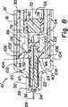
拡大図8に示すように、ストッパ構造(106)(108)は、ハウジング(12')の内面(16)に環状の隆起(106)(108)を有していることが好ましい。隆起(106)(108)はハウジング(12)とハウジング(12')に設けられた程度の違いしか差がなく、ストッパ構造(106)(108)は傾斜部(102)の外縁(104)の上方及び下方に位置している。注射時にカルプル(30)の前面(52)によって力が中央部(100)に加えられたときに、押しリング(40')が外向きに稍撓むことにより、カルプル(30)は外リム部(102)の外縁(104)が引掛かるようになる。注射の終了時には(図8に示す位置)、改良されたプランジャ(96)を更に押すと、プランジャは押しリング(40')の外リム部を押してストッパ構造から離し、押しリング(40')は針ホルダ(22)の拡大部(24)から外れる。この動作は、スライドする前シール(54)に対してカルプル(30)及びリム部材(72)を相対的に同時に動かし、2つの部分からなりスライドするピストンシール(66)からコア部(72)が外れる。改良されたプランジャ(96)及び押しリング(40')は、針ホルダ(22)は所定位置に留まっている状態で、前進する。
【0024】
押しリング(40')の厚みと形状は、このように動作するように選ばれる。材質又は厚みを変えることによって軽微な程度の柔軟性を有することが、押しリング(40')を外すことなく、カルプル(30)によって加えられた力に応じて引掛かり(jamming action)を確実に起こるようにすることができて望ましい。図9は、改良されたプランジャ(96)が図8に示す位置から更に押し付けられることによる結果を示しており、カルプル(30)の前部及び外壁(86)が押し付ける力により、押しリング(40')が前進して図8の位置から外れたことが判る。押しリング(40')は針ホルダ(22)の拡大部(24)から外れて前進し、同時に結合した前シール及びコア部材(72)は、カルプル(30)内を後退して該位置に保持される。
【0025】
図7は、図8の押しリング(40')の変形例を示し、最外周の縁(104)及び内周面(42')を有する中央開口(105)を具えている。内周面(42')はスライド可能に外面(26)を把持し、該外面(26)上にて内周面(42')は圧縮バネ(47)に抗しつつ針ホルダ(22)に支持される。この把持は摩擦的係合が好ましい。図7の中央本体部(100)は、内周面(42')と破線で示す円との間の部分にて示される。破線で示す円から外向きに延びた部分は、前に向かって傾斜した外リム部(102)であり、方向(109)は追加変更があってもよい。押しリング(40')は、多数の断片的な溝(110)を追加することにより、更に柔軟になり、該溝は外周に等間隔に配備され、最も傾いた部分(102)を通って半径方向に延びる。加えて、外縁の柔軟性を高めるために、半径方向を向いた多数の切り込み(112)が設けられる。
【0026】
プランジャの動作
動作時には、図1に示すように、カルプル(30)の後端は、プランジャの前部に連繋している。次に、プランジャ及びカルプル(30)の組合せ体が、ハウジング(12)の開口後部(18)に挿入され、カルプル(30)は、後方に延びた針(28)がシール(54)に孔が開けるまで、前に移動する。カルプル(30)の前部が押しリング(40)に達すると、抵抗感を感じる。前シール(54)内のソケット(58)は、針ホルダ(22)の後端部に嵌まる。医療器具は図2に示す初期位置にあり、使用される待機状態にある。
針(28)が患者の体内に挿入されたとき、プランジャ(80)は押されて、針(28)を通って薬剤室(60)内の内容物を患者に注射する。押しリング(40)は針ホルダ(22)を十分に強く保持しており、プランジャを押すことによりカルプル(30)に与えられる力に抵抗できる。プランジャ(80)が押されてカルプル(30)が空になったときは、2つの部分からなるピストンシール(66)は、前部(49)の縮径部分の後部に達する。これにより、外壁(86)の端部(94)は、リング部材(40)の外縁部に接する。このとき、ピストンシール(66)の壁部(74)は開口(50)に入っており、スライドする前シール(54)の後壁(56)に接する。この位置を、図3に示す注射終了位置と呼ぶ。
【0027】
プランジャを更に押すと、患者の体内から針が一瞬の内に引き抜かれ、針はハウジング(12)内に引き込まれ、引き込み部分はカルプル(30)内に留まるであろう。プランジャを押すと、内壁(84)はカルプル(30)の前部が達したリム(70)を押す。同時に外壁(86)は押しリング(40)の外縁部を押し、押しリング(40)は針ホルダ(22)から離れてスライドし始める。カルプル(30)の前部とプランジャ(80)の外壁(80)の連繋した動作により、押しリング(40)を接触面(26)(42)に沿って前にスライドさせる。同時に前シール(54)とコア部材(72)の前進は、ハウジング(12)内に支持された針ホルダ(22)により阻止される。リム部材(70)がカルプル(30)とともに前進する内壁(84)によって規制されているから、前シール(54)とコア部材(72)は一体となってカルプル(30)に対し、後退するように見える。プランジャ(80)が十分に前進し、押しリング(40)が針ホルダ(22)から離れたときは、コア部材(72)はリム部材(70)から緩む、又は略緩む。
押しリング(40)が針ホルダ(22)を解放したとき、親指キャップ(88)に残存している圧力により、スライドする前シール(54)はカルプル(30)の前部(49)の開口(50)を通って即座に動き、圧縮バネ(47)は針ホルダ(22)と針(28)をカルプル(30)の前端部(49)の開口(50)を通って薬剤室(60)内に移動させ、その位置で針ホルダ(22)と針(28)は引き込み方向に付勢されて止まる。親指キャップ(88)の縁は、拡大開口(19)に接して受けられ、プランジャ及び引き込まれた部品はハウジング(12)から外れることが困難又は不可能になる。
【0028】
押しリング(40)を外すのに必要な移動量は、針ホルダ(22)の接触面(26)(42)の長さ及び押しリングを夫々変更することにより、変えることができることが明白である。押しリングは接触面(26)(42)に沿うて摩擦によって針ホルダの拡大部に保持されることが好ましいが、一定の力で粘着が外れる粘着物を用いることも可能である。コア部材(72)はリム部材(70)に摩擦で係合していることが望ましい。カルプル(30)の開口の直径及びコア部材(72)の開口は、勿論針ホルダ(22)の拡大部及び前シールが通り抜けることができるほど、十分に大きくなければならない。コア部材(72)はリム部材(70)内に十分にきつく保持され、注射時にプランジャが押される際に生成される圧力に耐えている。
図5−図9に示す他の実施例の器具は、同様に作動する。違いは、押しリング(40')の変更と、押しリング(40')の縁部(104)を保持するストッパ構造(106)(108)である。カルプル(30)により押しリングの中央部に力が加わったときに、ディスク状の押しリングは外向きに広がろうとし、内壁面(16)にきつく嵌まる。針ホルダ(22)の拡大部も同様にきつく嵌まる。図5は注射待機位置を示し、図6は注射終了位置を示し、図2及び図3に対応する。
【0029】
図6に於いて、管状の外壁(86)の端部が押しリング(40')の外縁部を一旦押すと、嵌合状態が解除されて縁部(104)が解放される。ピストンシールがカルプル(30)の前に達する直前に押しリング(40')に接して、ストッパ構造から押しリングの縁部を解放することを容易とするように構成することもできる。押しリング(40')の縁部がストッパ構造から解放されるときに、プランジャ(80)とカルプル(30)は前進し、針ホルダ(22)から押しリングを取り外す。同時に前シールとコア部材(72)に対してカルプル(30)を前進させ、前記図9の引き込み位置に到達させる。前記の実施例のように、図5−図9に示す実施例は、1つの使用物を示さんとしたものである。別実施例では親指リングによって、引き込み後のプランジャ(80)を取り除くことができるが、部品は再組立が非常に困難な程に、分解される。特に、リム部材(70)はカルプル(30)の端に押し付けられており、取り除く方法はない。
【0030】
発明の最良形態に於いて、カルプル(30)はガラス製であり、ハウジング(12)とプランジャは従来から有るプラスチック製のシリンジである。スライドする前シール(54)及びリム部材(70)は、医療グレードのゴム製で、薬剤に影響を及ぼすことなく、長い寿命を有することが好ましい。同様に、コア部材は、ガラス又は硬質プラスチック製で所望の薬剤に反応しない。押しリングと針ホルダは、変形例に於ける使用の為に、ある程度の柔軟性を有する半硬質のポリプロピレンが選択されることが望ましい。
本発明は特定且つ好ましい実施例に関して記載してきたが、これは例示の為だけであり、本発明の範囲を限定せんとするものではない。種々の修正、変更、変化等が請求の範囲に定義される発明の精神及び範囲から外れることなくなされるべきである。
【図面の簡単な説明】
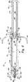
【図1】初期状態に於けるカルプルとプランジャを中央長手方向に沿って破断した断面図である。
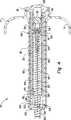
【図2】ハウジングの前、及び押しリングの後に配置されて前シールが両端針によって刺されているカルプルの前に設けられた引き込み機構を具えた引き込み可能な医療器具の断面図である。図2Aは、押しリングの外縁及びハウジングの壁の拡大図であり、内向きに径が稍小さくなる環状リングを示し、該リングは押しリングと針ホルダ組立体を引き込み方向に動くことを規制するのに役立つ。図2Bは、2つの部分を有するピストンシールの斜視図であり、図2の破断部に示されるカルプルの後部開口に留められる。
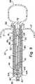
【図3】図2の引き込み可能な医療器具を中心線に沿って破断した断面図であり、プランジャが押されてカルプルの薬剤室から略全ての流体が放出され、注射が終了した状態を示す。
【図4】図3の引き込み可能な医療器具の断面図であり、プランジャが図3の注射終了位置から更に押されて、針保持構造がカルプル内に完全に引き込まれた位置を示す。
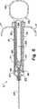
【図5】別の引き込み可能な医療器具を中心線に沿って破断した断面図であり、前に傾斜したディスク状の押しリングを示し、該リングの縁部はハウジングの内壁上の環状収縮部材間に位置し、注射待機位置にある。
【図6】図5の引き込み可能な医療器具に於いて、プランジャが第1の位置にまで押されて、略全ての流体がカルプルから放出され、プランジャの一部が押しリングの外縁に達し、更なるプランジャの押し込みが引込みをトリガーする状態を示す。
【図7】図5−図9のディスク状に形成された他の押しリングを示し、傾斜した外リムを有する前方傾斜部分を示し、押しリングは容易に撓み、前進移動に抗して引掛かりやすくなっている。
【図8】図6の医療器具の前部の拡大断面図であり、プランジャが所定位置にあってハウジングの内面に形成されたストッパ構造に対して押しリングの傾いた縁が撓んだり、引掛ったり押されたりすることを防ぐことを示している。
【図9】図5、図6、図8の引き込み可能な医療器具の断面図であり、プランジャが図8の位置を越えて押され、押しリングとカルプルを針ホルダに対して相対的に動かし、針ホルダと針の十分に引き込まれた位置に通路を形成する。[0001]
FIELD OF THE INVENTION
The present invention relates to a retractable medical device, and more particularly to a retractable device using a removable pharmaceutical container.
[0002]
BACKGROUND OF THE INVENTION
Conventional syringes have a barrel and a piston that fits tightly into the barrel, which draws fluid into the barrel through a needle in front of the barrel. The fluid is drawn through the needle and into the barrel. By depressing the plunger, air is expelled and fluid is injected. Many of these medical devices have been designed to retract the needle by various mechanisms. This is because there is a possibility that the needle will be contaminated by infectious diseases. As the risk of infectious diseases such as AIDS increases, it has become important to reduce the number of accidents that cause needles to pierce medical personnel. A great deal of effort has been devoted to the development of retractable syringes that are safe, effective and practical, low-cost and capable of mass production.
[0003]
There are fewer areas where all of this development effort is ignored, but it still exists in a significant area of syringes. That is, a syringe using a cartridge pre-filled with a chemical solution and a syringe using a double-ended hypodermic needle communicating with the cartridge to inject the contents of the cartridge. Prefilled syringe cartridges are called “carpules”. They are generally cylindrical tubes with a rupturable membrane at the front and a piston seal that is pushed forward with a plunger of a predetermined shape at the rear. The most common of these is the carpule syringe used by dentists when the dentist freezes the patient's gums before treating the teeth. In general, syringe enclosures with such pre-filled syringe cartridges are easy to retract the needle into the protective sheath to prevent the possibility of inadvertent harmful needle stick accidents. Can not. Thus, most syringes used by dentists for this purpose have a fixed needle and the needle must be covered by a sheath.
[0004]
There have been relatively few attempts to make a syringe with a retractable needle. However, the results are not completely satisfactory. Weltman, U.S. Pat. No. 3,306,290: Sullivan, U.S. Pat. No. 5,330,430: Haber, U.S. Pat. No. 4,820,275 describes that the instrument is more than the stroke required by the plunger itself to accommodate both the needle and cartridge. Above all, it suffers from the flaws that inevitably become much longer. Stanners, US Pat. No. 5,330,440, does not suffer from length defects, but uses a special thread to engage the plugs on both ends of the carpule and plunger. These connecting structures using thread must be mechanically connected to each other in order to pull the needle behind a special carpule. Retraction is done by manually removing the clasp.
[0005]
Although the needle can be retracted, these devices do not automatically retract the needle immediately by pushing the plunger further at the end of the injection when the needle is still in the patient's tissue. It is not desirable to control retraction slowly by hand. Inadvertent movement of the syringe risks damaging the patient's tissue. The ability to quickly retract the needle by meeting the above objectives and continuing the same operation during injection is a significant improvement of the Calpul syringe device. These and other objects are the subject of the present invention.
[0006]
Summary of the Invention
The present invention shows one use case of a retractable medical device and uses an improved carpule. The carpul has two parts: a sliding piston seal with a rear part and a sliding seal with a front part. The medical device is particularly suitable for use as a dental syringe, and in one embodiment, the thumb ring on the back of the plunger is common as a dental syringe. The syringe is designed to retract the needle after injection by a simple action of pressing and holding the plunger without releasing the syringe from the patient's body. The retractable portion and most of the needle are retracted into the carpule. The entire part of the needle is immediately pulled into the housing by pushing the plunger after injection.
[0007]
It differs from the conventional one in that the carpul is mainly closed at the front end and the rear end. The carpule has a cylindrical wall composed of a fluid chamber, a front end portion having an opening to the fluid chamber, and a rear end opening. The slidable front seal remains in the opening at the front end. In the conventional carpule, when the carpule is inserted, a hole is made in the front end portion by a needle extending backward, so that it is not necessary to provide a sliding seal to cover the opening of the front end portion. The improved carpul has two parts to keep the sliding piston seal in the rear end opening. The piston seal includes an outer rim portion that slides in contact with the wall of the fluid chamber, and a core portion that is slid and removed. The piston seal is moved by the plunger to the front end of the fluid chamber, releasing all fluid. When the plunger is moved in the retraction direction, the sliding front seal removes the core portion of the piston seal, passes through the rim portion, and enters the fluid chamber together with the following portions of the retraction mechanism.
[0008]
The retractable medical device has a tubular housing that includes a front end, a body, a rear end opening, and an interior surface defining a hollow interior. The retracting mechanism is provided at the front end of the housing. The retraction mechanism includes a needle holder, the needle holder having a long extending body, and a front end, a rear end, and an enlarged portion of the main body remote from the rear of the front end. The needle portion extends from the front and rear of the needle holder. A spring is provided below the enlarged portion of the needle holder and provides a pulling force to the needle holder.
[0009]
A releasable push ring is securely attached along the longitudinal direction of the inner surface around the enlarged portion of the needle holder. The push ring extends radially outward toward the inner wall of the housing. The outer edge of the push ring preferably slidably contacts the housing and holds the needle holder against the pulling force of the spring. A stopper is provided on the wall of the housing behind the push ring to prevent the push ring and the retracting mechanism from moving backward.
The above-described type of carpul is inserted into the housing with the front seal in contact with the rear end of the needle holder, and is pierced by the needle. The front part of the carpul faces the push ring. The plunger gradually supports the calpul as it enters the housing and pushes the piston forward to inject fluid through the needle.
[0010]
The plunger has a wall portion that pushes the outer rim portion of the piston seal, so that when retracted, the core portion can slide rearward relative to the rim portion without being obstructed by the plunger. The plunger also has another wall that pushes the outer edge of the push ring when the piston seal is pushed fully in front of the carpule at the end of the injection. When the plunger is further pushed, retraction occurs, and when the separable core part of the front seal and the piston seal is disengaged, the push ring is moved from the enlarged part of the needle holder. When the kull pulls forward with respect to the needle holder, the core portions of the front seal and the rear piston seal are disengaged, and the needle holder and the needle are carried through the front opening and into the safe kull pull by the pulling force. The kalpul and push ring move simultaneously to the reduced diameter end of the front of the housing, allowing the thumb cap to enter the back of the housing that does not reach the outer edge of the push ring. This is called “hidden” in the housing.
In the modified version of the plunger, a conventional thumb ring is used instead of the thumb cap. The thumb ring allows the plunger to retract after retracting, but the components cannot be reassembled for reuse. This is because there is virtually no way to take out the outer rim portion of the piston that is fastened adjacent to the wall immediately after the front opening.
[0011]
Other structures that can be used in any shape of the plunger include a disc-shaped push ring, the push ring comprising a central body portion, the central body portion being inclined forward to contact the housing wall. And an opening having an inner surface for slidably holding the enlarged portion of the needle holder.
The housing has a small stopper structure located on the lower side of the push ring, and provides resistance when the push ring moves and gets over the stopper structure. Other specification push rings push or clamp the outer rim against the wall of the housing. This is because the push ring is so flexible that it is arranged so that the central body part advances forward relative to the edge held by the stop structure. This prevents the Calpul from releasing the push ring from the needle holder early by pushing the plunger during injection. In the “injection end position”, the outer wall of the plunger extending along the wall of the housing pushes the outer edge of the push ring. When the plunger moves forward, the outer edge of the push ring is released from the lock surface, and the push ring is easily detached. The tilted outer rim has a tilted portion that serves to act on the stopper structure on the inner wall surface of the housing and holds the push ring until released by the plunger.
[0012]
The parts are relatively simple and are prone to mass production and automatic manufacturing. The push ring is assembled with the needle holder without the needle facing upward, the spring is placed on the needle holder, and the housing is lowered towards the assembly to compress the spring as the push ring and needle holder are advanced Is done. The needle is inserted from the front. This is the most practical retractable dentist carpul syringe, with the same action as the injection, withdrawing the needle directly and withdrawing the needle directly from the patient's tissue, eliminating the risk of piercing a person with a contaminated needle. ing. This instrument is unique in that it contains needles that are contaminated with used carpules.
[0013]
Detailed Description of the Invention
In the following description, the same parts are indicated by the same reference numerals, and the similar parts are indicated by the reference numerals with a prime mark ('). The retractable medical device (10) is shown in a standby state in FIG. The tubular housing (12) has a front portion (14), an inner wall surface (16), and an open rear end portion (18). The open rear end (18) has an enlarged portion (19) that receives a thumb cap (88) on the rear of the plunger (80) having a pair of finger grips (17).
[0014]
The retracting mechanism (20) is provided at the front portion (14) of the housing (12). As better shown in FIG. 3, the retraction mechanism (20) comprises a long extending needle holder body (22), the holder body (22) having an enlarged portion (24) having a short outer surface (26) facing outwardly. )have. It will be described later that the needle holder body (22) surrounds and holds the both-end needle (28), and the needle forms a flow path to the carpule (30). The needle (28) is a continuous needle as shown in FIG. 3, or includes a portion extending forward and rearward, and engages the patient's tissue and the drug supply part in the carpule (30), respectively. It is a separate needle that is connected as possible. The front part (14) of the housing (12) has a reduced diameter nose (32) in which an opening (34) into which the front end part (36) of the needle holder (22) is fitted is formed. The front end (36) has a smaller diameter than the needle holder body (22). The flange on the front end and nose (32) serves as a pedestal (38) for the needle holder (22) in the nose (32).
[0015]
The needle holder (22) is held in place by a push ring (40), the push ring has an inwardly facing inner surface (42) with a hole in the center, and the outer surface (26 ) Is firmly held. The push ring (40) has an outer rim or edge (44) shown here in the form of an arch, and is preferably provided slidably in contact with the inner wall (16) of the housing (12). An annular stopper (46) having a slightly raised portion from the inner wall (16) is used to prevent the retracting mechanism from moving backwards.
[0016]
Retraction mechanism(20)When attaching the housing from the back of the housing,(40)As the slides forward, the push ring(40)The slightly elastic edge of the stopper(46)It is desirable to force over.The stopper (46) may be of a larger diameter, in which case the push ring (40) needs to be mounted from the front of the housing (12). In that case, the housing (12) is a housing having two parts instead of a single housing as shown in the figure. It has a removable front and is attached to the cylindrical housing after the retracting mechanism is attached. The stopper is a separate ridge or separate piece extending inward that prevents the push ring (40) from moving in the retracting direction. The base formed by the enlarged portion (24) receives the end of the urging means, which is a compression spring (47), and the compression spring (47) applies a retraction force to the needle holder (22).
[0017]
Returning to FIG. 1, FIG. 2 and FIG. 2A. The outer edge (44) of the push ring (40) has a relatively flat central portion compared to the inclined portions (48) on both sides. The small contact surface tends to increase the unit pressure at the interface between the push ring (40) and the inner wall (16),A certain amount of manufacturing tolerance variation is compensated.
Please refer to FIG. The carpule (30) includes a reduced diameter front (49) having a relatively short opening (50) and a front surface (52). A slidable front seal (54) is fastened in front of the opening (50). The front seal (54) is a cup-shaped member having a rigid back surface (56), a side surface (55) in contact with the opening, and an open side serving as a socket (58). As shown in FIG. 4, the side surface (55) has an arcuate contour when not compressed. Accordingly, the slide friction amount of the front seal is adjusted, and the seal (54) moves along the wall surface of the opening (50).
[0018]
The medicine chamber (60) includes a front part (49), a long tubular wall (62) having an inner surface (64), and a slidable piston seal (66). The back of the drug chamber (60) remains in the opening (68) behind the carpule (30) and is a slidable piston seal (66) having two parts. The piston seal (66) shown in FIG. 2B has an outwardly facing rim member (70) and a forwardly extending wall (74) and includes a removable core member (72). As better shown in FIG. 2, the rim member (70) is a suitable length cylindrical seal with an opening having an inner surface (76) in its longitudinal direction. The rim member is a sleeve surrounding the releasable core member (72).
[0019]
The core member (72) contacts the inner surface (76) with a land (78). The land (78) has a longitudinal surface in contact with the rim member (70) along the longitudinal direction, and the longitudinal surface is shorter than the inner surface (76). Alternatively, the land is a raised portion from the rim member (70), and the core member (72) has a uniform cylindrical surface. The length of the land (78), the composition and fit of the slidable core member (72) are such that when the plunger (80) is pushed, the piston seal with two parts is within the drug chamber (60). It is selected so as to keep the state of the bag even when it receives the generated internal pressure.
Although the forwardly extending wall (74) of the slidable core (72) is shown in a cylindrical shape, the wall can be constituted by a plurality of individual protrusions or leg pieces forming a socket, such as an opening (82). The socket (82) supports the rear end of the needle (28). The wall portion (74) is formed so as to fit inside the opening (50), has a mouth of a kull pull, extends forward, and contacts the front seal (54). The portion (wall) (74) extending in front of the core member (72) allows the front seal member (54) and the core member (72) to move together when the unit starts to be retracted. To do. Thus, the seal member and the core member are in a position where both become free when the needle holder (22) is released.
[0020]
Returning to FIG. 1 and FIG. The plunger (80) has an inner wall (84) and an outer wall (86) that are parallel and spaced apart from each other. These walls are preferably tubular in view of strength stability. The rear part of the inner wall (84) and the outer wall (86) are connected by a hidden thumb cap (88) that fits the enlarged part (19) of the rear opening (18) of the housing (12). I can receive it. The inner wall (84) extends to the end surface (90) that engages the end surface (92) of the rim member (70) shown in FIG. 2B. The inner wall (84) enters the kalpul opening (68) with the end surface (90) in contact with the end surface (92), but does not contact any part of the removable core member (72).
When the plunger (80) is pushed to move the two-part piston seal (66) from the position shown in FIG. 2 to the end of the injection position shown in FIG. 3, the outer wall (86) is attached to the housing (12). Gradually support the carpule (30) in the entered state. When the plunger and the carpule are fitted to each other, the outer wall (86) is tightly received by the inner wall (16), and the combination of the plunger and the carpule provides a certain degree of lateral stability. The outer wall (86) is preferably longer than the inner wall (84), and a part of the outer wall (86) is engaged with the rear end of the carpul as shown in FIG. This makes it easy to insert the carpule (30) and the plunger (80) into the housing (12). The end (94) of the outer wall (86) is slidably contacted along the wall surface (16), thereby stably supporting the combined carpul (30) and plunger (80).
[0021]
More importantly, the relative lengths of the inner wall (84) and outer wall (86) of the plunger (80) are approximately as the annular end (94) reaches the outer edge of the push ring (40) in preparation for retraction. At the same time, the piston seal (66) is provided so as to reach the front of the carpule (30).
Pushing the plunger (80) further causes the kull pull (30) to move relative to the housing, similar to the plunger for the housing, and the outer wall (86) of the plunger and / or the front of the kull pull (52) moves to the needle holder (22). The push ring (40) is removed from the and the push ring falls into the housing.
With the rear part of the needle (28) extending through the seal (54), the rear end of the needle holder (22) fits into the socket (58). The rear end of the needle holder (22) has a smaller diameter than the socket (58), controls the amount of friction between the side surface (55) and the side surface (50), or the side surface of the socket (58) and the needle holder (22) The combined diameter of the rear side is designed as such. The socket (58) is configured so that, when retracted, the front seal member (54) is left at the rear of the needle holder (22) without being inclined or causing pressure deformation (jam), and the carpul (30). It is also useful for aligning with the needle holder (22).
When the plunger (80) is pushed further beyond the end of the injection position shown in FIG. 3, the plunger (80) moves the push ring and at the same time moves the carpule (30) relative to the housing. Yes. As the kalpul moves past the end of the injection position shown in FIG. 3, the rim member (70) moves relative to the core member (72) and the front seal (54) in preparation for retraction. The piston seal in the carpule (30) in a position where the plunger (80) is fully pushed and almost all of the fluid from the drug chamber (60) has been released through the needle holder (22). When the end of (66) is reached, the needle holder (22), the front seal (54) and the core member (72) are in contact with each other.
[0022]
Another retractable medical device is shown as the retractable medical device (10 ′) of FIGS. The medical device 10 'of FIG. 5 is similar in most parts to the retractable medical device shown in FIGS. As described above, the kull pull (30) is attached to the tubular housing (12) having the inner wall surface (16). The improved plunger (96) differs from the plunger (80) in that the thumb cap (88) is replaced with a thumb ring (98). This is rather similar to a plunger that dentists are accustomed to, but does not have the feature that a syringe with a hidden thumb cap cannot be reused. The plunger (96) has the same inner wall (84) and outer wall (86) as the plunger (80), is designed in the same way as the plunger (80) and operates a two-part sliding piston seal (66) The fluid from the medicine chamber (60) is released. The structure (10 ′) is different from the structure (10) except that the thumb ring is different in that the pull-in mechanism is changed. The pull-in mechanism (20 ′) is the same as the pull-in mechanism (20) except that a push ring (40 ′) is used instead of the push ring (40). The push ring (40 ′) has a main body (100) in the center, and the diameter thereof is much smaller than the diameter of the front part (49) of the carpule (30), as shown in FIG. The push ring (40 ′) has an outer rim portion (102) inclined forward, and the rim portion has an outer edge (104) in contact with the inner wall surface (16).
[0023]
As shown in the enlarged view 8, the stopper structure (106) (108) preferably has an annular ridge (106) (108) on the inner surface (16) of the housing (12 '). The ridges (106) and (108) differ only in the degree of difference provided in the housing (12) and the housing (12 ′), and the stopper structures (106) and (108) are formed on the outer edge (104) of the inclined portion (102). Located above and below. When a force is applied to the central part (100) by the front face (52) of the carpule (30) during injection, the push ring (40 ') bends outward, causing the carpule (30) to The outer edge (104) of (102) is hooked. At the end of injection (position shown in FIG. 8), further pushing the modified plunger (96) pushes the outer rim of the push ring (40 ′) away from the stopper structure, and the push ring (40 ′) The needle holder (22) is disengaged from the enlarged portion (24). This operation is performed by simultaneously moving the carpule (30) and the rim member (72) relative to the sliding front seal (54) so that the core part (72) is moved from the two-part sliding piston seal (66). Come off. The improved plunger (96) and push ring (40 ') advance with the needle holder (22) remaining in place.
[0024]
The thickness and shape of the push ring (40 ') is chosen to operate in this way. A slight degree of flexibility by changing material or thickness ensures jamming action according to the force applied by the carpule (30) without removing the push ring (40 '). It can be desirable to happen. FIG. 9 shows the result of the improved plunger (96) being pushed further from the position shown in FIG. 8, with the force of the front and outer walls (86) of the carpul (30) being pushed by the push ring (40). It can be seen that ') has advanced and deviated from the position of FIG. The push ring (40 ') moves forward away from the enlarged portion (24) of the needle holder (22), and at the same time, the front seal and the core member (72) combined with each other are retracted in the Karpulu (30) and held in this position. Is done.
[0025]
FIG. 7 shows a variation of the push ring (40 ′) of FIG. 8, comprising a central opening (105) having an outermost peripheral edge (104) and an inner peripheral surface (42 ′). The inner peripheral surface (42 ') slidably grips the outer surface (26), and on the outer surface (26), the inner peripheral surface (42') resists the compression spring (47) while holding the needle holder (22). Supported. This gripping is preferably frictional engagement. The central main body (100) in FIG. 7 is shown at a portion between the inner peripheral surface (42 ′) and a circle indicated by a broken line. A portion extending outward from a circle indicated by a broken line is an outer rim portion (102) inclined forward, and the direction (109) may be additionally changed. The push ring (40 ′) is made more flexible by adding a number of fragmented grooves (110), which are evenly spaced on the outer periphery and radiused through the most inclined part (102). Extend in the direction. In addition, a number of radially incisions (112) are provided to increase the flexibility of the outer edge.
[0026]
Plunger operation
In operation, as shown in FIG. 1, the rear end of the carpule (30) is connected to the front of the plunger. Next, the combination of the plunger and the calpule (30) is inserted into the rear opening (18) of the housing (12), and the calpule (30) has a needle (28) extending rearward and a hole in the seal (54). Move forward until you open it. When the front of the carpul (30) reaches the push ring (40), a sense of resistance is felt. The socket (58) in the front seal (54) is fitted to the rear end of the needle holder (22). The medical device is in the initial position shown in FIG.
When the needle (28) is inserted into the patient's body, the plunger (80) is pushed to inject the contents in the drug chamber (60) through the needle (28) into the patient. The push ring (40) holds the needle holder (22) sufficiently strongly and can resist the force applied to the carpule (30) by pushing the plunger. When the plunger (80) is pushed and the carpule (30) is emptied, the two-part piston seal (66) reaches the rear part of the reduced diameter part of the front part (49). Thus, the end portion (94) of the outer wall (86) is in contact with the outer edge portion of the ring member (40). At this time, the wall portion (74) of the piston seal (66) enters the opening (50), and contacts the rear wall (56) of the front seal (54) that slides. This position is called the injection end position shown in FIG.
[0027]
Pushing the plunger further will pull the needle out of the patient's body in an instant, the needle will be pulled into the housing (12), and the retracted portion will remain in the carpule (30). When the plunger is pushed, the inner wall (84) pushes the rim (70) reached by the front part of the carpul (30). At the same time, the outer wall (86) pushes the outer edge of the push ring (40), and the push ring (40) begins to slide away from the needle holder (22). The push ring (40) is slid forward along the contact surfaces (26) and (42) by an operation in which the front part of the carpule (30) and the outer wall (80) of the plunger (80) are connected. At the same time, the advancement of the front seal (54) and the core member (72) is prevented by the needle holder (22) supported in the housing (12). Since the rim member (70) is regulated by the inner wall (84) that moves forward together with the carpule (30), the front seal (54) and the core member (72) are moved backward with respect to the calpule (30). Looks like. When the plunger (80) is sufficiently advanced and the push ring (40) is separated from the needle holder (22), the core member (72) is loosened or substantially loosened from the rim member (70).
When the push ring (40) releases the needle holder (22), due to the pressure remaining in the thumb cap (88), the sliding front seal (54) opens the front part (49) of the carpule (30) ( 50) and the compression spring (47) moves the needle holder (22) and needle (28) through the opening (50) in the front end (49) of the carpule (30) into the drug chamber (60). In this position, the needle holder (22) and the needle (28) are urged in the retracting direction and stopped. The edge of the thumb cap (88) is received against the enlarged opening (19), making it difficult or impossible for the plunger and retracted part to be detached from the housing (12).
[0028]
It is clear that the amount of movement required to remove the push ring (40) can be changed by changing the length of the contact surface (26) (42) of the needle holder (22) and the push ring, respectively. . The push ring is preferably held by the enlarged portion of the needle holder by friction along the contact surfaces (26) and (42), but it is also possible to use an adhesive that can be removed by a certain force. It is desirable that the core member (72) is frictionally engaged with the rim member (70). The diameter of the opening of the carpule (30) and the opening of the core member (72) must of course be large enough to allow the enlarged part of the needle holder (22) and the front seal to pass through. The core member (72) is held tightly within the rim member (70) and withstands the pressure generated when the plunger is pushed during injection.
The other embodiment instruments shown in FIGS. 5-9 operate similarly. The difference is the change of the push ring (40 ′) and the stopper structure (106) (108) that holds the edge (104) of the push ring (40 ′). When a force is applied to the central portion of the push ring by the carpule (30), the disk-like push ring tends to spread outward and tightly fits to the inner wall surface (16). The enlarged part of the needle holder (22) fits in the same way. FIG. 5 shows the injection standby position, FIG. 6 shows the injection end position, and corresponds to FIG. 2 and FIG.
[0029]
In FIG. 6, once the end of the tubular outer wall (86) presses the outer edge of the push ring (40 '), the fitted state is released and the edge (104) is released. It can also be configured to facilitate the release of the edge of the push ring from the stopper structure by contacting the push ring (40 ′) just before the piston seal reaches the front of the kull pull (30). When the edge of the push ring (40 ') is released from the stopper structure, the plunger (80) and the carpule (30) move forward and remove the push ring from the needle holder (22). At the same time, the kull pull (30) is advanced relative to the front seal and the core member (72) to reach the retracted position shown in FIG. Like the above-described embodiment, the embodiment shown in FIGS. 5 to 9 shows one used item. In another embodiment, the thumb ring can remove the retracted plunger (80), but the parts are disassembled so that they are very difficult to reassemble. In particular, the rim member (70) is pressed against the end of the carpule (30) and there is no way to remove it.
[0030]
In the best mode of the invention, the carpule (30) is made of glass, and the housing (12) and the plunger are conventional plastic syringes. The pre-sliding seal (54) and the rim member (70) are preferably made of medical grade rubber and have a long life without affecting the drug. Similarly, the core member is made of glass or hard plastic and does not react to the desired drug. For the push ring and the needle holder, it is desirable to select a semi-rigid polypropylene having a certain degree of flexibility for use in the modification.
While this invention has been described with reference to specific and preferred embodiments, this is for purposes of illustration only and is not intended to limit the scope of the invention. Various modifications, changes, changes and the like should be made without departing from the spirit and scope of the invention as defined in the appended claims.
[Brief description of the drawings]
FIG. 1 is a cross-sectional view of a carpule and a plunger cut along a central longitudinal direction in an initial state.
FIG. 2 is a cross-sectional view of a retractable medical device with a retracting mechanism disposed in front of the housing and in front of the carpule that is positioned after the push ring and the front seal is pierced by a double-ended needle. FIG. 2A is an enlarged view of the outer edge of the push ring and the wall of the housing, showing an annular ring with an inwardly decreasing diameter that restricts the push ring and needle holder assembly from moving in the retracted direction. To help. FIG. 2B is a perspective view of a two-part piston seal, fastened to the rear opening of the carpule shown in the fracture of FIG.
FIG. 3 is a cross-sectional view taken along the center line of the retractable medical device of FIG. 2, showing a state where injection has been completed after the plunger has been pushed to release almost all fluid from the drug chamber of the carpul. .
4 is a cross-sectional view of the retractable medical device of FIG. 3, showing the position where the plunger has been further pushed from the end of injection position of FIG. 3 and the needle retaining structure has been fully retracted into the carpule.
FIG. 5 is a cross-sectional view taken along the centerline of another retractable medical device, showing a pre-tilted disc-shaped push ring, the edge of the ring being an annular contraction member on the inner wall of the housing Located in the middle and in the injection standby position.
FIG. 6 shows a retractable medical device of FIG. 5 in which the plunger is pushed to a first position, substantially all of the fluid is released from the carpule, and a portion of the plunger reaches the outer edge of the push ring; A further plunger push-in triggers a retraction.
FIG. 7 shows another push ring formed in the disk shape of FIGS. 5-9, showing a front beveled portion with a beveled outer rim, the push ring being easily deflected and hooked against forward movement It has become easier.
8 is an enlarged cross-sectional view of the front portion of the medical device of FIG. 6, in which the inclined edge of the push ring is bent or hooked against the stopper structure formed on the inner surface of the housing with the plunger in place. It shows that it is prevented from being pushed or pushed.
9 is a cross-sectional view of the retractable medical device of FIGS. 5, 6, and 8, wherein the plunger is pushed beyond the position of FIG. 8 to move the push ring and the carpule relative to the needle holder. The passage is formed in the fully retracted position of the needle holder and the needle.
Claims (31)
Translated fromJapanese前部、内壁面、開口した後端部を具える管状のハウジング(12)と、
ハウジング(12)に嵌まっており、スライド可能な前シール(54)を具えた開口が形成された前部と、解除可能なコア部材(72)を具え、2つの部分からなるスライド可能なピストンシール(66)を有し、後部に開口を形成して後方に延びる壁を具えたカルプル(30)と、
外壁と内壁を具え、外壁はハウジング(12)内に入りながらカルプル(30)を徐々に支持し、内壁はピストンシール(66)をカルプル(30)の前部まで動かすプランジャ(80)と、
ハウジング(12)の前部に設けられて、拡大部を有し、ハウジング(12)に当接して前方への移動が規制される針ホルダ(22)と、針ホルダ(22)の拡大部をしっかりと保持し、ハウジング(12)の内壁面との当接により後方移動を規制され前方移動のみが許される押しリング(40)とを具え、針ホルダ(22)は針ホルダ本体から前方及び後方に延びる針部と、針ホルダ(22)に引き込み力を与える付勢手段を有している引き込み機構(20)と、
カルプル(30)は、ハウジング(12)に挿入可能であり、押しリング(40)に対向する前開口と、後方に延びた針部に孔を開けられる前シール(54)を具え、
プランジャ(80)が押しリング(40)を前方に押すことにより、押しリング(40)が針ホルダ(22)から外れて、押しリング(40)による針ホルダ(22)の後方移動規制が解除されることにより、付勢手段によって針ホルダ(22)及び針がカルプル(30)内に引き込まれることが自由になる医療器具。In a retractable medical device for releasing fluid from Carpul,
A tubular housing (12) having a front, an inner wall, an open rear end, and
A two-part slidable piston fitted with a housing (12), having a front part with an opening with a slidable front seal (54) and a releasable core member (72) A carpule (30) having a seal (66) and having a wall extending rearward with an opening at the rear;
A plunger (80) comprising an outer wall and an inner wall, the outer wall gradually supporting the kull pull (30) while entering the housing (12), and the inner wall moving the piston seal (66) to the front of the kull pull (30);
A needle holder (22) provided on the front part of thehousing(12), having an enlarged part,abutting on thehousing(12)and being restricted from moving forward, and an enlarged part of the needle holder (22) The needle holder (22) is forward and rearward from the needle holder main body witha push ring(40) that holds firmly andis restricted from moving backward by contact with the inner wall of thehousing(12)and only allowed to move forward. A retraction mechanism (20) having a needle portion extending to the needle holder and a biasing means for applying a retraction force to the needle holder (22),
The carpul (30) is insertable into the housing (12), and includes a front opening facing the push ring (40) and a front seal (54) that can be pierced in the needle portion extending rearward.
When the plunger (80) pushes the push ring (40)forward , the push ring (40) is disengaged from theneedle holder(22), and the rearward movement restrictionof the needle holder(22)by thepush ring(40)is released. By this, the medical device in which the needle holder (22) and the needle are free to be pulled into the carpule (30)by the biasing means.
2つの部分からなりスライドするピストンシール(66)は、取り外し可能なコア部材(72)を囲むのに適当な長さのリム部材を有し、リム部材とコア部材(72)は、前記リム部材の長さよりも長手方向に短い長さで互いに接している。The medical device according to claim 1,
The two-part sliding piston seal (66) has a rim member of an appropriate length to enclose the removable core member (72), and the rim member and the core member (72) include the rim member. Are in contact with each other with a length shorter in the longitudinal direction than the length.
プランジャ(80)の外壁はプランジャ(80)の内壁を越えて前に延び、カルプル(30)の後部を一部保持して、カルプル(30)がハウジング(12)内に位置決めされることに役だっている。In the medical instrument according to claim 2,
The outer wall of the plunger (80) extends forward beyond the inner wall of the plunger (80) and holds part of the rear part of the carpule (30) to help position the carpule (30) in the housing (12). ing.
プランジャ(80)が押されてカルプル(30)が空になると、プランジャ(80)の内壁と外壁の相対的長さはピストンシール(66)がカルプル(30)の端に達するような長さであり、そのとき同時にプランジャ(80)の外壁が押しリング(40)に達するように形成され、それによってプランジャ(80)が更に押し込まれて、押しリング(40)が針ホルダ(22)から外れると、プランジャ(80)と同じくカルプル(30)がハウジング(12)に対して移動する。The medical device according to claim 1,
When the plunger (80) is pushed and the carpule (30) is emptied, the relative length of the inner and outer walls of the plunger (80) is such that the piston seal (66) reaches the end of the calpule (30). At the same time, the outer wall of the plunger (80) is formed so as to reach the push ring (40), whereby the plunger (80) is pushed further, and the push ring (40) is detached from the needle holder (22). As with the plunger (80), the carpule (30) moves relative to the housing (12).
プランジャ(80)が押されてピストンシール(66)がカルプル(30)の端に接したときに、針ホルダ(22)、前シール(54)、コア部材は互いに接し、押しリング(40)を外すように更にプランジャ(80)が押されたときに、引き込みに備えて、前シール(54)とコア部材に対して相対的にカルプル(30)と押しリング(40)を動かす。In the medical instrument according to claim 4,
When the plunger (80) is pushed and the piston seal (66) comes into contact with the end of the carpule (30), the needle holder (22), the front seal (54), and the core member are in contact with each other, and the push ring (40) is When the plunger (80) is further pushed so as to be removed, the kull pull (30) and the push ring (40) are moved relative to the front seal (54) and the core member in preparation for retraction.
ハウジング(12)の内壁面は、押しリング(40)の下側に位置する小さなストッパ構造を有し、押しリング(40)が移動して該ストッパ構造を越えるときに抵抗感を与える。The medical device according to claim 1,
The inner wall surface of the housing (12) has a small stopper structure located below the push ring (40), and gives resistance when the push ring (40) moves and exceeds the stopper structure.
押しリング(40)は、ストッパ構造の背後にて、中央本体部と前に傾斜した外リム部を有し、注射時にカルプル(30)によって押しリング(40)を押す力は、プランジャ(80)の外壁がストッパ構造から押しリング(40)の外リム部を外すまでは、押しリング(40)を外すことなく、ハウジング(12)に外リム部を掛らせる。In the medical instrument according to claim 6,
The push ring (40) has a central body part and an outer rim part inclined forward at the back of the stopper structure, and the force pushing the push ring (40) by the carpule (30) during the injection is the plunger (80) The outer rim portion is hung on the housing (12) without removing the push ring (40) until the outer wall of the pusher removes the outer rim portion of the push ring (40) from the stopper structure.
傾いた外リムは、前に傾いた複数の部分を有し、該部分はハウジング(12)の内壁面のストッパ構造と互いに作用して、プランジャ(80)によって解除されるまで、分離可能部材をその位置に保持する。In the medical instrument according to claim 7,
The tilted outer rim has a plurality of forwardly tilted portions that interact with the stopper structure on the inner wall surface of the housing (12) to release the separable member until released by the plunger (80). Hold in that position.
プランジャ(80)が押されてカルプル(30)が空になったときに、プランジャ(80)の内壁と外壁の相対的な長さは、ピストンシール(66)がカルプル(30)の底に達し、そのとき殆ど同時にプランジャ(80)の外壁が押しリング(40)に達する長さになり、それによりプランジャ(80)が更に押し込まれると、プランジャ(80)とともにカルプル(30)がハウジング(12)に対して相対的に移動して、押しリング(40)は針ホルダ(22)から外される。In the medical instrument according to claim 6,
When the plunger (80) is pushed and the calpule (30) is emptied, the relative length of the inner and outer walls of the plunger (80) is such that the piston seal (66) reaches the bottom of the calpule (30). At the same time, the outer wall of the plunger (80) has reached a length that reaches the push ring (40), and when the plunger (80) is further pushed in, the calpule (30) together with the plunger (80) is moved into the housing (12). The push ring (40) is removed from the needle holder (22).
プランジャ(80)が押されてピストンシール(66)がカルプル(30)の底に接したときに、針ホルダ(22)、前シール(54)、コア部材は互いに接し、押しリング(40)を外すように更にプランジャ(80)が押されたときに、引き込みに具えて、前シール(54)とコア部材に対してカルプル(30)と押しリング(40)を動かす。In the medical instrument according to claim 9,
When the plunger (80) is pushed and the piston seal (66) comes into contact with the bottom of the carpule (30), the needle holder (22), the front seal (54), and the core member are in contact with each other, and the push ring (40) is When the plunger (80) is further pushed so as to be removed, the kull pull (30) and the push ring (40) are moved relative to the front seal (54) and the core member in preparation for retraction.
2つの部分から構成されたスライドするピストンシール(66)は、取り外し可能なコア部材を囲むのに適当な長さのリム部材を有し、リム部材とコア部材は前記リム部材の長さよりも短い長手方向の長さで互いに接する。The medical device according to claim 10, wherein
The two-part sliding piston seal (66) has a rim member of an appropriate length to enclose the removable core member, the rim member and the core member being shorter than the length of the rim member. They are in contact with each other in the longitudinal direction.
針ホルダ(22)は突部を有し、カルプル(30)は前部に、カルプル(30)がハウジング(12)内に挿入されたときに突部を受けるソケットを有し、これによりカルプル(30)と針ホルダ(22)は容易に一列に揃う。The medical device according to claim 1,
The needle holder (22) has a protrusion, the calpule (30) has a socket on the front, and a socket that receives the protrusion when the calpule (30) is inserted into the housing (12). 30) and the needle holder (22) are easily aligned.
前シール(54)は開口した側部を有するカップ状に形成された部材であり、該開口した側部は前記ソケットとして役立つ。The medical instrument according to claim 12,
The front seal (54) is a cup-shaped member having an open side, and the open side serves as the socket.
前端部、本体部、開口した後部を形成する壁を具え、該壁は中空の内部を形成する内表面を形成している管状のハウジング(12)と、
ハウジング(12)の前端部に設けられた引き込み機構とを具え、
引き込み機構は、
長く延びた本体を有し、本体は前部と、後部と、前部の背後から離れて位置する拡大部を有して、ハウジング(12)に当接して前方への移動が規制される針ホルダ(22)と、
針ホルダ(22)の前部及び後部から延びる針部と、
針ホルダ本体の拡大部の下側に設けられ、針ホルダ本体に引き込み力を与えるバネ(47)と、
針ホルダ(22)の拡大部の回りをしっかりと把持し、ハウジング(12)の内壁にスライド可能にしっかりと接して外向きに延び、針ホルダ(22)をバネ(47)による引き込み力に抗して所定位置に保持し、ハウジング(12)の内壁面との当接により後方移動を規制され前方移動のみが許される押しリング(40)と、
放出すべき流体を満たすためのカルプル(30)とを具え、該カルプル(30)は、開口を形成しスライド可能で孔が開けられる前シール(54)を具えた前端と、後方に延びた壁と2つの部分からなりスライド可能なピストンシール(66)を有する後部開口とを具えた本体とを具え、カルプル(30)はハウジング(12)内にスライドし、それにより前シール(54)は針により孔が開けられる様に構成され、
ハウジング(12)内に入り、スライド可能なピストンを前方に押し、徐々にカルプル(30)を支持するプランジャ(80)であって、プランジャ(80)が注射終了位置に達して略全ての流体を放出し、プランジャ(80)の一部が押しリング(40)に達するまで針を通じて流体を放出し、
プランジャ(80)は注射終了位置を越えてカルプル(30)に沿って押されることができ、プランジャ(80)が押しリング(40)を押すことにより、押しリング(40)が針ホルダ(22)から外れて、バネ(47)によって針ホルダ(22)及び針が引き込まれ、針ホルダ(22)と針は前部開口を通ってカルプル(30)内の安全な位置に運ばれる医療器具。In a retractable medical device for releasing fluid from a carpul (30),
A tubular housing (12) comprising a wall forming a front end, a body part, an open rear part, the wall forming an inner surface forming a hollow interior;
A retracting mechanism provided at the front end of the housing (12),
The retraction mechanism is
The needle has a long body, the body has a front part, a rear part, and an enlarged part located away from the back of the front part, anda needlethat contacts thehousing(12)and is restricted from moving forward. A holder (22);
A needle portion extending from the front and rear of the needle holder (22);
A spring (47) provided on the lower side of the enlarged portion of the needle holder body, and for applying a pulling force to the needle holder body;
Grip firmly around the enlarged part of the needle holder (22), slidably contact the inner wall of the housing (12) and extend outward to resist the pulling force of the spring (47). And holding in place,a push ring (40) thatis restricted from moving backward by contact with the inner wall of thehousing(12)and only allowed to move forward ,
A carpule (30) for filling the fluid to be discharged, the carpule (30) having a front end with a front seal (54) forming an opening, slidable and perforated, and a wall extending rearward And a body with a two-part slidable piston seal (66) and a rear opening, the carpule (30) slides into the housing (12), so that the front seal (54) is a needle. It is configured so that a hole can be opened by
A plunger (80) that enters the housing (12), pushes the slidable piston forward, and gradually supports the carpule (30), and the plunger (80) reaches the injection end position and receives almost all of the fluid. Release fluid through the needle until a part of the plunger (80) reaches the push ring (40),
The plunger (80) can be pushed along the carpule (30) beyond the injection end position, and when the plunger (80) pushes the push ring (40), the push ring (40) becomes the needle holder (22). And the needle holder (22) and the needle are retracted by the spring (47), and the needle holder (22) and the needle are carried through the front opening to a safe position in the carpule (30).
ハウジング(12)の内壁面は、押しリング(40)の下側に位置する小さなストッパ構造を有し、押しリング(40)が移動して該ストッパ構造を越えるときに抵抗感を与える。The medical device according to claim 14, wherein
The inner wall surface of the housing (12) has a small stopper structure located below the push ring (40), and gives resistance when the push ring (40) moves and exceeds the stopper structure.
押しリング(40)は、ストッパ構造の背後に、中央本体部と前に傾いた外リム部を有し、注射時にカルプル(30)によって押しリング(40)を押す力は、ハウジング(12)に外リム部を掛らせ、プランジャ(80)の外壁がストッパ構造から押しリング(40)の外リム部を外すまでは、押しリング(40)を外さない。The medical instrument according to claim 15,
The push ring (40) has a central body part and an outer rim part tilted forward behind the stopper structure, and the force pushing the push ring (40) by the carpule (30) during injection is applied to the housing (12). The push ring (40) is not removed until the outer rim is engaged and the outer wall of the plunger (80) removes the outer rim of the push ring (40) from the stopper structure.
傾いた外リムは、前に傾いた複数の部分を有し、該部分はハウジング(12)の内壁面のストッパ構造と互いに作用して、プランジャ(80)によって解除されるまで、解除可能部材を所定位置に保持する。The medical device according to claim 16, wherein
The tilted outer rim has a plurality of forwardly tilted portions that interact with the stopper structure on the inner wall surface of the housing (12) to disengage the releasable member until released by the plunger (80). Hold in place.
カルプル(30)は針に孔を開けられるべきシールされた前開口を有する前端部、プランジャ(80)によって動かされるピストンシール(66)が位置する後端部を有し、プランジャ(80)はピストンを前に押してカルプル(30)の内容物を両端針を通って空にする引き込み可能な医療器具に於いて、
カルプル(30)は、前開口にスライド可能な前シール(54)を有し、ピストンシール(66)の中央にスライド可能に外されるコア部材(72)を有し、スライド可能なコア部材(72)はカルプル(30)の内容物の殆ど全量を押し出すために、プランジャ(80)が押されることに対応して、前シール(54)の隣に並ぶことになり、
針ホルダ(22)をカルプル(30)内に引き込む為の開口が、前開口からスライド可能な前シール(54)をスライドさせて取り外し、及びピストンからスライド可能なコア部材をスライドさせて取り外すことによって形成され、
針ホルダ(22)は、針ホルダ(22)を囲みハウジング(12)の内壁面との当接により後方移動を規制され前方移動のみが許される取り外し可能な押しリング(40)によって、針と共に位置決めされ保持されて、押しリング(40)はハウジング(12)の内壁面の一部に強制的に移動可能に接触し、針を通ってカルプル(30)の内容物を空にした後にプランジャ(80)を押すことにより、カルプル(30)及び押しリング(40)が針ホルダ(22)に対して相対的に移動し、それにより押しリング(40)が取り外され、針ホルダ(22)をカルプル(30)内に引き込む通路が開くことを特徴とする医療器具。A tubular housing (12) having an inner wall and a rear end opening, a needle holder (22)which is spring-biased andabuts against thehousing(12)and is restricted from moving forward, and a double-ended needle. A retraction mechanism (20) provided at the front of (12), and a carpule (30) designed to fit into the housing (12),
The carpul (30) has a front end with a sealed front opening to be pierced in the needle, a rear end on which a piston seal (66) moved by the plunger (80) is located, the plunger (80) being a piston In a retractable medical device that pushes forward to empty the contents of the carpule (30) through the needles at both ends,
The carpule (30) has a front seal (54) slidable in the front opening, a core member (72) slidably removed in the center of the piston seal (66), and a slidable core member ( 72) will line up next to the front seal (54) in response to the plunger (80) being pushed to push out almost the entire contents of the carpule (30),
Opening the needle holder (22) into the carpule (30) by sliding and removing the front seal (54) slidable from the front opening, and sliding and removing the slidable core member from the piston Formed,
The needle holder (22) is positioned together with the needle bya detachable push ring (40) that surrounds the needle holder (22) andis restricted from moving backward by contact with the inner wall of thehousing(12)and only allowed to move forward. The push ring (40) is forcibly movably contacted with a part of the inner wall surface of the housing (12), and the plunger (80) is emptied after emptying the contents of the carpule (30) through the needle. ) Is moved relative to the needle holder (22), the push ring (40) is removed, and the needle holder (22) is 30) A medical device characterized in that a passage to be drawn in is opened.
注射時は、カルプル(30)の前端は、プランジャ(80)の押圧による前方の動きに抗してホルダ及び/又は押しリング(40)によって支持される。The medical device according to claim 18, wherein
At the time of injection, the front end of the carpule (30) is supported by the holder and / or the push ring (40) against the forward movement caused by the pressing of the plunger (80).
ピストンが前進してカルプル(30)の内容物を放出するときに、前シール(54)とコア部材との間に延びた壁がある。The medical device according to claim 19, wherein
There is a wall extending between the front seal (54) and the core member as the piston advances to release the contents of the carpul (30).
プランジャ(80)の押圧によってカルプル(30)が空になったときに、コア部材の一部がカルプル(30)の前開口内に入る。The medical device according to claim 20,
When the calpule (30) is emptied by the pressing of the plunger (80), a part of the core member enters the front opening of the calpule (30).
カルプル(30)はその中でピストンが作動する本体部を有し、本体部は前開口よりも大きな内径を有し、それによって側方のストッパ面が前記開口の背後に形成され、ピストンの前進端のストッパとなる。The medical device according to claim 21,
The carpule (30) has a body part in which the piston operates, and the body part has a larger inner diameter than the front opening, whereby a lateral stopper surface is formed behind the opening to advance the piston. It becomes an end stopper.
内壁面と後部開口を形成して長く延びた壁を具える管状のハウジング(12)と、
ハウジング(12)の前に設けられた引き込み可能な機構であって、ハウジング(12)内に置かれて、長く延びた本体と拡大部とを有してハウジング(12)に当接して前方への移動が規制される針ホルダ(22)と、該針ホルダ(22)の拡大部にしっかりと設けられてハウジング(12)の内壁面との当接により後方移動を規制され前方移動のみが許される押しリング(40)とを具え、押しリング(40)は針ホルダ(22)に引き込み力を与える付勢要素とは対向する側にて、ハウジング(12)の内壁にスライド可能に保持された外部を具え、針ホルダ(22)は前方及び後方に延び、流体の通路を有する針部を具え、
取り外し可能なカルプル(30)は、長く延びた壁を具え、該壁は前部には針ホルダ(22)が通る開口を、後ろには開口を形成し、カルプル(30)は前開口にスライド可能に留まるシールと、後開口にスライド可能に留まるピストンシール(66)を具え、カルプル(30)の内部は流体室を構成し、
カルプル(30)は、押しリング(40)の後方にてハウジング(12)中に配備でき、該押しリング(40)は、流体室へ流体の流通可能に前シール(54)を貫通して延びている後方に延びた針部を具えており、
ピストンシール(66)は、外リム部と、強制的に取り外しできるコア(72)を有し、流体室から略全ての流体を放出するために、ピストンシール(66)はカルプル(30)の長く延びた壁にスライド可能に接した状態でカルプル(30)内の前位置にまで移動可能であり、
プランジャ(80)は、ピストンシール(66)の外リム部を押すことにより、ピストンシール(66)をカルプル(30)内の前位置まで動かす内壁を有し、
プランジャ(80)が押しリング(40)を押すことにより、押しリング(40)が針ホルダ(22)から外れて、前シール(54)がカルプル(30)の開口から外れ、ピストンシール(66)のコア部材(72)が外リム部から外れ、付勢要素によって針ホルダ(22)及び針が引き込まれ、それにより付勢要素は針ホルダ(22)を流体室に運んで針を引き込むことを特徴とする医療器具。In a retractable medical device for releasing fluid from a carpul (30),
A tubular housing (12) comprising an inner wall and a rear opening to form a long extending wall;
A retractable mechanism provided in front of the housing (12), which is placed in the housing (12), has a long extending body and an enlarged portion, andabuts thehousing(12)to the front The needle holder (22) in whichthe movement of the needle holder (22)is restricted,and the rear movement is restricted by contact with the inner wall surface of thehousing(12) that is firmly provided in the enlarged portion of the needle holder (22), andonly forward movement is allowed. The push ring (40) is slidably held on the inner wall of the housing (12) on the side opposite to the biasing element that applies the pulling force to the needle holder (22). Comprising an exterior, the needle holder (22) extending forward and backward, comprising a needle portion having a fluid passage;
The removable carpule (30) has a long wall that forms an opening through which the needle holder (22) passes in the front and an opening in the back, and the carpule (30) slides into the front opening. A seal that stays in place and a piston seal (66) that stays slidable in the rear opening, and the interior of the carpule (30) forms a fluid chamber,
The carpule (30) can be deployed in the housing (12) behind the push ring (40), the push ring (40) extending through the front seal (54) to allow fluid to flow to the fluid chamber. Has a needle part extending backward,
The piston seal (66) has an outer rim and a core (72) that can be forcibly removed, and the piston seal (66) has a length longer than that of the carpule (30) in order to release almost all fluid from the fluid chamber. It can move to the front position in Kalpul (30) in a state where it slidably contacts the extended wall,
The plunger (80) has an inner wall that moves the piston seal (66) to the front position in the carpule (30) by pushing the outer rim of the piston seal (66).
When the plunger (80) pushes the push ring (40), the push ring (40) is detached from the needle holder (22), the front seal (54) is removed from the opening of the kull pull (30), and the piston seal (66) The core member (72) is removed from the outer rim portion, and the urging element draws the needle holder (22) and the needle, whereby the urging element carries the needle holder (22) to the fluid chamber and retracts the needle. Features medical equipment.
前部、内壁面、後端開口を具える管状のハウジング(12)と、
ハウジング(12)の前部に設けられた引き込み可能な機構であって、ハウジング(12)に当接して前方への移動が規制される針ホルダ(22)と、該針ホルダ(22)から前方及び後方に延びた針部と、針ホルダ(22)に引き込み力を与える付勢要素と、ハウジング(12)の内壁面とともに作用して、針ホルダ(22)と針を使用位置に保持するとともに後方移動を規制され前方移動のみが許される押しリング(40)とを具えた機構と、
ハウジング(12)に嵌まり、スライド可能な前シール(54)にてシールされる前開口を有し、薬剤室(60)を背後に有するカルプル(30)とを具え、
プランジャ(80)が押しリング(40)を押すことにより、押しリング(40)が針ホルダ(22)から外れて、バネ(47)によって針ホルダ(22)及び針が引き込まれ、少なくとも針の一部は薬剤室(60)に入り、針を安全に引き込むことを特徴とする医療器具。In a retractable medical device for releasing fluid from a carpul (30),
A tubular housing (12) with a front, inner wall, rear end opening;
A retractable mechanism provided at a front portion of thehousing(12), the needle holder (22) being in contact with thehousing(12)and being restricted from moving forward, and the front from the needle holder (22) And the needle portion extending backward, the urging element for applying a pulling force to the needle holder (22), and the inner wall surface of the housing (12) to hold the needle holder (22) and the needle in the use position. A mechanism comprising a push ring (40) that isrestricted from moving backward and only allowed to move forward ;
A carpule (30) fitted in the housing (12), having a front opening sealed by a slidable front seal (54), and having a drug chamber (60) behind,
When the plunger (80) pushes the push ring (40), the push ring (40) is detached from the needle holder (22), and the needle holder (22) and the needle are pulled by the spring (47), so that at least one of the needles is pulled. The medical device is characterized in that the part enters the drug room (60) and the needle is safely retracted.
カルプル(30)はピストンの前にシールを、ピストンの中央部に取り外し可能なコア部材を有し、
コア部材はプランジャ(80)の押圧によってシールの隣に達して、カルプル(30)の内容物を放出し、
前開口からシールが取り外され、コア部材がピストンから取り外されることにより、針ホルダ(22)をカルプル(30)に引き込む為に開口が開放され、
針ホルダ(22)は針が延びた状態にて、ハウジング(12)の内壁面との当接により後方移動を規制され前方移動のみが許される押しリング(40)が針ホルダ(22)を囲むことにより、位置決めされ及び保持され、針ホルダ(22)はハウジング(12)の内壁面によって規制されており、
カルプル(30)の内容物が空になるまで、プランジャ(80)を押すと、プランジャ(80)が押しリング(40)を押すことにより、押しリング(40)が針ホルダ(22)から外れて、バネ(47)によって針ホルダ(22)及び針が引き込まれ、それにより針ホルダ(22)と針は前開口を通ってカルプル(30)内に入ることを特徴とする医療器具。Retractable medical device, a tubular housing (12) with front, inner wall, and rear end opening, and a retractable mechanism provided at the front of the housing (12) that can be retractedA needle holder (22) that is spring-biased andabuts against thehousing(12)to restrict forward movement and a double-ended needle, and a carpule (30) designed to fit inside the housing (12). The seal has a front opening which has a front end which is pierced by a needle and a rear end which is located by a piston seal (66) which is moved by a plunger (80), the plunger (80) having a piston In a medical instrument that pushes forward to empty the contents of the carpule (30) through the needles at both ends,
Carpul (30) has a seal in front of the piston and a removable core member in the center of the piston,
The core member reaches next to the seal by pressing the plunger (80) and releases the contents of the carpule (30),
By removing the seal from the front opening and removing the core member from the piston, the opening is opened to draw the needle holder (22) into the carpule (30),
The needle holder (22) surrounds the needle holder (22) witha push ring (40)that restrictsbackward movement by allowing contact with the inner wall surface of thehousing(12)and allowsonly forward movement when the needle is extended. The needle holder (22) is regulated by the inner wall surface of the housing (12).
When the plunger (80) is pushed until the contents of the carpule (30) are empty, the plunger (80) pushes the push ring (40) so that the push ring (40) is detached from the needle holder (22). The medical device is characterized in that the needle holder (22) and the needle are retracted by the spring (47), whereby the needle holder (22) and the needle enter the carpule (30) through the front opening.
針ホルダ(22)とハウジング(12)の間に延びて、ハウジング(12)内に引き込み機構を解除可能に保持し、ハウジング(12)の内壁面との当接により後方移動を規制され前方移動のみが許される押しリング(40)と、
カルプル(30)は前開口にスライド可能な前シール(54)を、前開口の背後に収納室を、ピストンシール(66)内に取り外し可能なコア部材を設け、
カルプル(30)の内容物が針を経て空になった後にプランジャ(80)を押すと、プランジャ(80)が押しリング(40)を押すことにより、押しリング(40)が針ホルダ(22)から外れて、前シール(54)がカルプル(30)の開口から外れ、ピストンシール(66)のコア部材(72)が外リム部から外れ、バネ(47)によって針ホルダ(22)及び針がカルプル(30)内に自動的に引き込まれることを特徴とする医療器具。A retractable medical device having a front housing, an inner wall surface, and a tubular housing (12) having an opening at the rear end, and a retractable mechanism that is spring-biased so as to be retractableand abuts on thehousing(12).This is a carpule (30) designed to fit inside the housing (12)with a needle holder (22)that is restricted from moving forward and a double-ended needle at the front of the housing (12). The seal has a front end which is pierced by a needle and a rear end where a piston seal (66) moved by a plunger (80) during injection is located, inside the carpule (30). In a medical device comprising a storage chamber for fluid contents behind the opening and the piston being pushed forward to empty the contents of the carpule (30) through the needles at both ends,
Extends between the needle holder (22) and the housing (12), holds the retracting mechanism in thehousing(12) soas to be releasable,and rearward movement is restricted by contact with the inner wall surface of thehousing(12)and moves forward The push ring (40), whichis only allowed ,
Carpule (30) is provided with a front seal (54) slidable in the front opening, a storage chamber behind the front opening, and a removable core member in the piston seal (66).
When the plunger (80) is pushed after the contents of the carpule (30) are emptied through the needle, the plunger (80) pushes the push ring (40), so that the push ring (40) is pushed into the needle holder (22). The front seal (54) is removed from the opening of the carpule (30), the core member (72) of the piston seal (66) is removed from the outer rim, and the needle holder (22) and the needle are moved by the spring (47). A medical device that is automatically drawn into the carpule (30).
プランジャ(80)は、カルプル(30)を徐々に支持する外壁と、プランジャ(80)が押されたときにピストンシール(66)をカルプル(30)内にて徐々に前進させる内壁を有する。The medical device of claim 26,
The plunger (80) has an outer wall that gradually supports the calpul (30), and an inner wall that gradually advances the piston seal (66) within the calpul (30) when the plunger (80) is pushed.
カルプル(30)が空になった後にプランジャ(80)を押すことにより、管状のハウジング(12)に対して相対的にカルプル(30)が前進することに対応して、ハウジング(12)内に引き込み機構を保持する押しリング(40)が解除される。The medical instrument according to claim 27,
By pushing the plunger (80) after the carpule (30) is empty, the carpule (30) moves forward relative to the tubular housing (12) to accommodate the The push ring (40) holding the retracting mechanism is released.
針ホルダ(22)はカルプル(30)が前進したときに、スライド可能な前シール(54)のストッパとして役立ち、それによりカルプル(30)の前シール(54)が外されて針ホルダ(22)が通る開口が形成される。The medical device according to claim 28,
The needle holder (22) serves as a stopper for the slidable front seal (54) when the kull pull (30) is advanced, so that the front seal (54) of the kull pull (30) is removed and the needle holder (22) An opening through which is passed is formed.
プランジャ(80)を押すことによりカルプル(30)が空になった後に、取り外し可能なコア部材と前シール(54)は一緒に動く。The medical device according to claim 1,
After the carpule (30) is emptied by pushing the plunger (80), the removable core member and the front seal (54) move together.
取り外し可能なコア部材又は前シール(54)の延長部は、コア部材と前シール(54)間の接触を生じさせ、コア部材と前シール(54)を一緒になって移動させる。The medical device according to claim 30, wherein
The removable core member or extension of the front seal (54) creates contact between the core member and the front seal (54) and moves the core member and the front seal (54) together.
Applications Claiming Priority (3)
| Application Number | Priority Date | Filing Date | Title |
|---|---|---|---|
| US09/034,411 | 1998-03-04 | ||
| US09/034,411US5997512A (en) | 1998-03-04 | 1998-03-04 | Retractable dental syringe |
| PCT/US1999/004734WO1999044653A1 (en) | 1998-03-04 | 1999-03-03 | Retractable dental syringe |
Related Child Applications (1)
| Application Number | Title | Priority Date | Filing Date |
|---|---|---|---|
| JP2005119424ADivisionJP4153503B2 (en) | 1998-03-04 | 2005-04-18 | Carpul used for retractable dental syringes |
Publications (2)
| Publication Number | Publication Date |
|---|---|
| JP2002505160A JP2002505160A (en) | 2002-02-19 |
| JP3834476B2true JP3834476B2 (en) | 2006-10-18 |
Family
ID=21876235
Family Applications (2)
| Application Number | Title | Priority Date | Filing Date |
|---|---|---|---|
| JP2000534250AExpired - Fee RelatedJP3834476B2 (en) | 1998-03-04 | 1999-03-03 | Retractable dental syringe |
| JP2005119424AExpired - Fee RelatedJP4153503B2 (en) | 1998-03-04 | 2005-04-18 | Carpul used for retractable dental syringes |
Family Applications After (1)
| Application Number | Title | Priority Date | Filing Date |
|---|---|---|---|
| JP2005119424AExpired - Fee RelatedJP4153503B2 (en) | 1998-03-04 | 2005-04-18 | Carpul used for retractable dental syringes |
Country Status (6)
| Country | Link |
|---|---|
| US (1) | US5997512A (en) |
| EP (1) | EP1059950A4 (en) |
| JP (2) | JP3834476B2 (en) |
| CN (1) | CN1188180C (en) |
| AU (1) | AU2893499A (en) |
| WO (1) | WO1999044653A1 (en) |
Cited By (2)
| Publication number | Priority date | Publication date | Assignee | Title |
|---|---|---|---|---|
| JP2012519512A (en)* | 2009-03-06 | 2012-08-30 | サノフィ−アベンティス・ドイチュラント・ゲゼルシャフト・ミット・ベシュレンクテル・ハフツング | Seal member for a syringe with a retractable needle |
| KR101801657B1 (en) | 2015-07-14 | 2017-11-27 | 소후 인코포레이티드 | Cartridge that prevents nozzle from splipping off |
Families Citing this family (52)
| Publication number | Priority date | Publication date | Assignee | Title |
|---|---|---|---|---|
| US6090077A (en) | 1995-05-11 | 2000-07-18 | Shaw; Thomas J. | Syringe plunger assembly and barrel |
| US7300416B2 (en) | 1995-08-22 | 2007-11-27 | Specialized Health Products International | Pre-filled retractable needle injection ampoules |
| US6123688A (en)* | 1995-08-22 | 2000-09-26 | Mdc Investment Holdings, Inc. | Pre-filled retractable needle injection devices |
| US5800395A (en) | 1996-12-05 | 1998-09-01 | Mdc Investment Holdings, Inc. | Medical device with retractable needle |
| US6221055B1 (en)* | 1998-03-04 | 2001-04-24 | Retractable Technologies, Inc. | Retractable dental syringe |
| US7572263B2 (en) | 1998-04-01 | 2009-08-11 | Arthrocare Corporation | High pressure applicator |
| US6783515B1 (en)* | 1999-09-30 | 2004-08-31 | Arthrocare Corporation | High pressure delivery system |
| GB9928884D0 (en)* | 1999-12-08 | 2000-02-02 | Nmt Group Plc | Closure assembly |
| US7476324B2 (en)* | 2000-07-14 | 2009-01-13 | Ferrate Treatment Technologies, Llc | Methods of synthesizing a ferrate oxidant and its use in ballast water |
| BR0112825A (en)* | 2000-07-28 | 2003-07-01 | Mdc Invest Holdings Inc | Process for injecting medicine from a medical device that has a needle with a sharp tip and medical device |
| US6572584B1 (en) | 2000-08-07 | 2003-06-03 | Retractable Technologies, Inc. | Retractable syringe with reduced retraction force |
| US6764471B2 (en)* | 2000-11-13 | 2004-07-20 | Alexander E. Lee | Dental syringe |
| US6387078B1 (en)* | 2000-12-21 | 2002-05-14 | Gillespie, Iii Richard D. | Automatic mixing and injecting apparatus |
| WO2002074361A2 (en)* | 2001-03-15 | 2002-09-26 | Mdc Investment Holdings, Inc. | Retractable needle medical device for injecting fluid from a pre-filled cartridge |
| DE20106464U1 (en)* | 2001-04-12 | 2001-08-02 | Pac Tech - Packaging Technologies GmbH, 14641 Nauen | Device for applying solder balls |
| US6800066B2 (en) | 2001-04-26 | 2004-10-05 | Nmt Group Plc | Retractable needle syringe |
| US7410478B2 (en)* | 2001-08-17 | 2008-08-12 | Chih Ming Wang | Safety syringe with needle retracting mechanism |
| US7004929B2 (en) | 2002-03-29 | 2006-02-28 | Mdc Investment Holdings, Inc. | Safety pre-filled cartridge injector |
| US6613024B1 (en)* | 2002-06-18 | 2003-09-02 | Frank V. Gargione | Single hand controlled dosage syringe |
| DE10257173B4 (en)* | 2002-12-03 | 2005-10-13 | Siemens Ag | Method for applying solder material, use of a system for laser-assisted direct metal deposition therefor and contact surfaces with solder deposits |
| BRPI0514909B8 (en) | 2004-09-03 | 2021-06-22 | L O M Laboratories Inc | safety-type syringe for use with a hypodermic needle |
| ES2427631T3 (en) | 2004-10-14 | 2013-10-31 | Midland Medical Devices Holdings, Llc | Medical safety syringe with retractable needle |
| MX2007006974A (en)* | 2004-12-09 | 2007-10-11 | West Pharm Serv Inc | Automatic injection and retraction syringe. |
| US8123724B2 (en)* | 2004-12-09 | 2012-02-28 | West Pharmaceutical Services Of Delaware, Inc. | Auto-injection syringe having vent device |
| US7476215B2 (en)* | 2005-09-21 | 2009-01-13 | Choi Fat Lam | Automatic retractable safety syringe |
| US7753878B2 (en)* | 2005-09-22 | 2010-07-13 | Tyco Healthcare Group Lp | Safety needle with lockout mechanism |
| AU2006295443B2 (en)* | 2005-09-22 | 2012-03-29 | Kpr U.S., Llc | Needle retraction structure |
| JP2009520508A (en) | 2005-09-22 | 2009-05-28 | タイコ・ヘルスケアー・グループ・エルピー | Manual retractable safety needle with rigid blade structure |
| AU2006292108B2 (en) | 2005-09-22 | 2012-08-02 | Kpr U.S., Llc | Non-axial return spring for safety needle |
| US7988675B2 (en)* | 2005-12-08 | 2011-08-02 | West Pharmaceutical Services Of Delaware, Inc. | Automatic injection and retraction devices for use with pre-filled syringe cartridges |
| US7846135B2 (en) | 2006-02-24 | 2010-12-07 | Midland Medical Holding LLC | Retractable needle syringe with needle trap |
| AT502791B1 (en)* | 2006-04-06 | 2007-05-15 | Pharma Consult Ges M B H & Co | Injection syringe, has plastic needle holder enclosing stainless steel injection needle, where holder receives injection solution in relation to interior of cylinder and is sealed off by sealing insert, by which rear end of needle protrudes |
| TW200743500A (en)* | 2006-05-26 | 2007-12-01 | ming-zheng Xu | Disposable syringe |
| CA2682699A1 (en)* | 2007-03-21 | 2008-09-25 | Midland Medical Devices Holdings, Llc | Safety medical syringe with retractable needle and including a plunger that is received within a barrel |
| JP2009125312A (en)* | 2007-11-22 | 2009-06-11 | Ming-Jeng Shiu | Cartridge-type disposable syringe |
| ES2675849T3 (en)* | 2008-03-28 | 2018-07-13 | Orion Diagnostica Oy | Sampling and dispensing method |
| US9259533B2 (en)* | 2008-03-31 | 2016-02-16 | Covidien Lp | Safety needle with spring biased retraction mechanism |
| CN101318040B (en)* | 2008-06-05 | 2013-10-23 | 刘文杰 | Improved barrel type push bar for needle whip-back type safety syringe and syringe thereof |
| WO2010006380A1 (en)* | 2008-07-17 | 2010-01-21 | Medigard Limited | A retractable syringe |
| US12097357B2 (en) | 2008-09-15 | 2024-09-24 | West Pharma. Services IL, Ltd. | Stabilized pen injector |
| US9101739B2 (en)* | 2009-02-17 | 2015-08-11 | Entellus Medical, Inc. | Balloon catheter inflation apparatus and methods |
| US8574193B2 (en)* | 2011-03-07 | 2013-11-05 | Midland Medical Devices Holdings, LLC. | Retractable syringe with locking plunger |
| JP2015123297A (en)* | 2013-12-27 | 2015-07-06 | 株式会社吉野工業所 | Syringe-type ejection container |
| EP2905040A1 (en)* | 2014-02-11 | 2015-08-12 | Sulzer Mixpac AG | Discharger |
| US9867944B1 (en)* | 2014-03-17 | 2018-01-16 | Matthew L Justus | Multi-mode medication dispenser |
| TWI681792B (en) | 2014-10-31 | 2020-01-11 | 加拿大商L O M 實驗股份有限公司 | Retractable needle syringe |
| WO2016115628A1 (en) | 2015-01-20 | 2016-07-28 | L.O.M. Laboratories Inc. | Retractable needle syringe with unitary propellant release module |
| EP3130368A1 (en)* | 2015-07-31 | 2017-02-15 | Sulzer Mixpac AG | Child-resistant discharger |
| BR112019018459B1 (en) | 2017-03-09 | 2023-10-24 | Retractable Technologies, Inc. | DENTAL SAFETY SYRINGE |
| US10617831B2 (en) | 2017-10-30 | 2020-04-14 | Retractable Technologies, Inc. | Frontal attachment for dental syringe with oblique needle advancement and retraction |
| US12042639B2 (en) | 2020-09-03 | 2024-07-23 | Retractable Technologies, Inc. | Medical syringe with retractable needle and modified plunger handle with concave pressure application surface |
| GB2604584B (en)* | 2021-02-28 | 2023-08-02 | Owen Mumford Ltd | Injector apparatus facilitating automatic needle withdrawal |
Family Cites Families (25)
| Publication number | Priority date | Publication date | Assignee | Title |
|---|---|---|---|---|
| US3306290A (en)* | 1964-02-14 | 1967-02-28 | Harold S Weltman | Automatically retractable needle syringe |
| DE2212778A1 (en)* | 1971-05-19 | 1973-09-20 | Heinz Hampel | Throw-away plastic hypodermic - for use with standard cylindrical ampoules |
| US4927414A (en)* | 1987-04-29 | 1990-05-22 | Kulli John C | Syringe with safety retracting needle |
| US4820275A (en)* | 1987-12-21 | 1989-04-11 | Habley Medical Technology Corporation | Retractable needle syringe with integral spring |
| US5188599A (en)* | 1989-07-11 | 1993-02-23 | Med-Design, Inc. | Retractable needle system |
| US5019044A (en)* | 1989-08-14 | 1991-05-28 | Tsao Chien Hua | Safety hypodermic syringe |
| US5084018A (en)* | 1989-08-14 | 1992-01-28 | Tsao Chien Hua | Safety syringe |
| US5125898A (en)* | 1990-03-22 | 1992-06-30 | Harry Kaufhold, Jr. | Disposable syringe with automatic needle retraction |
| US5211629A (en)* | 1991-12-23 | 1993-05-18 | Pressly William B S | Safety syringe |
| US5613952A (en)* | 1991-12-23 | 1997-03-25 | Syringe Develpoment Partners | Safety syringe |
| JPH05285219A (en)* | 1992-03-05 | 1993-11-02 | Habley Medical Technol Corp | Syringe assembly for injecting fluid |
| US5330440A (en)* | 1992-10-21 | 1994-07-19 | Stanners Sydney D | Reverse thread carpule dental safety syringe |
| US5405326A (en)* | 1993-08-26 | 1995-04-11 | Habley Medical Technology Corporation | Disposable safety syringe with retractable shuttle for luer lock needle |
| US5531694A (en)* | 1993-08-31 | 1996-07-02 | Clemens; Anton H. | Needle retraction system |
| US5385551A (en)* | 1993-09-22 | 1995-01-31 | Shaw; Thomas J. | Nonreusable medical device with front retraction |
| WO1995011713A1 (en)* | 1993-10-28 | 1995-05-04 | Lok-Tek Syringe Pty Ltd | Hypodermic syringe with retractable needle mount |
| US5330430A (en)* | 1993-12-06 | 1994-07-19 | Sullivan Robert J | Retractable syringe applicator |
| US5634909A (en)* | 1993-12-09 | 1997-06-03 | Schmitz; William L. | Auto-retracting needle injector system |
| US5423758A (en)* | 1993-12-16 | 1995-06-13 | Shaw; Thomas J. | Retractable fluid collection device |
| US5501670A (en)* | 1995-03-31 | 1996-03-26 | Sak; Robert F. | Syringe system providing retraction of needle cannula into disposable cartridge |
| US6090077A (en)* | 1995-05-11 | 2000-07-18 | Shaw; Thomas J. | Syringe plunger assembly and barrel |
| US5632733A (en)* | 1995-05-11 | 1997-05-27 | Shaw; Thomas J. | Tamperproof retractable syringe |
| CA2264532C (en)* | 1996-09-03 | 2004-04-20 | Mdc Investment Holdings, Inc. | Pre-filled retractable needle injection devices |
| US5681292A (en)* | 1996-10-29 | 1997-10-28 | Retrax Safety Systems, Inc. | Retractable needle and syringe combination |
| US5891104A (en)* | 1997-01-10 | 1999-04-06 | Univec, Inc. | Hypodermic syringe having retractable needle |
- 1998
- 1998-03-04USUS09/034,411patent/US5997512A/ennot_activeExpired - Lifetime
- 1999
- 1999-03-03AUAU28934/99Apatent/AU2893499A/ennot_activeAbandoned
- 1999-03-03WOPCT/US1999/004734patent/WO1999044653A1/enactiveApplication Filing
- 1999-03-03CNCNB998052736Apatent/CN1188180C/ennot_activeExpired - Fee Related
- 1999-03-03JPJP2000534250Apatent/JP3834476B2/ennot_activeExpired - Fee Related
- 1999-03-03EPEP99909811Apatent/EP1059950A4/ennot_activeWithdrawn
- 2005
- 2005-04-18JPJP2005119424Apatent/JP4153503B2/ennot_activeExpired - Fee Related
Cited By (2)
| Publication number | Priority date | Publication date | Assignee | Title |
|---|---|---|---|---|
| JP2012519512A (en)* | 2009-03-06 | 2012-08-30 | サノフィ−アベンティス・ドイチュラント・ゲゼルシャフト・ミット・ベシュレンクテル・ハフツング | Seal member for a syringe with a retractable needle |
| KR101801657B1 (en) | 2015-07-14 | 2017-11-27 | 소후 인코포레이티드 | Cartridge that prevents nozzle from splipping off |
Also Published As
| Publication number | Publication date |
|---|---|
| CN1188180C (en) | 2005-02-09 |
| JP2002505160A (en) | 2002-02-19 |
| WO1999044653A1 (en) | 1999-09-10 |
| AU2893499A (en) | 1999-09-20 |
| EP1059950A4 (en) | 2006-07-19 |
| JP4153503B2 (en) | 2008-09-24 |
| EP1059950A1 (en) | 2000-12-20 |
| US5997512A (en) | 1999-12-07 |
| CN1298314A (en) | 2001-06-06 |
| JP2005253995A (en) | 2005-09-22 |
Similar Documents
| Publication | Publication Date | Title |
|---|---|---|
| JP3834476B2 (en) | Retractable dental syringe | |
| RU2131748C1 (en) | Automatic or manual device for injections of liquid medicinal agent | |
| EP1225933B1 (en) | Retractable dental syringe | |
| JP5599394B2 (en) | Retractable syringe | |
| JP2738514B2 (en) | Automatic injection device | |
| CA2455160C (en) | One-use retracting syringe with positive needle retention | |
| JP3729736B2 (en) | Self-retracting catheter introducer | |
| US5176656A (en) | Automatically positioned needle sheath for a disposable hypodermic syringe | |
| US7601139B2 (en) | Spring launched needle safety clip | |
| JP4903318B2 (en) | A hypodermic syringe with a selectively retractable needle | |
| JP3399524B2 (en) | Injection device | |
| JPH0211163A (en) | Injector | |
| CN110520175A (en) | Autoinjector Device | |
| JP2010188176A (en) | Safety shield system for prefilled syringe | |
| JPH09503947A (en) | Syringe or similar parenteral device | |
| JP2004504889A (en) | Retractable needle medical device that injects liquid from a pre-filled cartridge | |
| JPH08512214A (en) | Syringe | |
| US5484413A (en) | Disposable medical syringe with safety protection | |
| US7544180B2 (en) | Safety syringes | |
| CA2409297C (en) | Retractable needle and syringe combination | |
| US5725501A (en) | Safety syringe system | |
| KR100673284B1 (en) | Disposable Shrink Needle with Positive Needle Retention | |
| US20140163518A1 (en) | Safety Syringe | |
| MXPA00008658A (en) | Retractable dental syringe | |
| HK1194313B (en) | Modular gas-actuated retractable needle assembly |
Legal Events
| Date | Code | Title | Description |
|---|---|---|---|
| A977 | Report on retrieval | Free format text:JAPANESE INTERMEDIATE CODE: A971007 Effective date:20041125 | |
| A131 | Notification of reasons for refusal | Free format text:JAPANESE INTERMEDIATE CODE: A131 Effective date:20050111 | |
| A601 | Written request for extension of time | Free format text:JAPANESE INTERMEDIATE CODE: A601 Effective date:20050407 | |
| A602 | Written permission of extension of time | Free format text:JAPANESE INTERMEDIATE CODE: A602 Effective date:20050415 | |
| A521 | Request for written amendment filed | Free format text:JAPANESE INTERMEDIATE CODE: A523 Effective date:20050418 | |
| A02 | Decision of refusal | Free format text:JAPANESE INTERMEDIATE CODE: A02 Effective date:20051206 | |
| A521 | Request for written amendment filed | Free format text:JAPANESE INTERMEDIATE CODE: A523 Effective date:20060306 | |
| A521 | Request for written amendment filed | Free format text:JAPANESE INTERMEDIATE CODE: A523 Effective date:20060322 | |
| A911 | Transfer to examiner for re-examination before appeal (zenchi) | Free format text:JAPANESE INTERMEDIATE CODE: A911 Effective date:20060425 | |
| TRDD | Decision of grant or rejection written | ||
| A01 | Written decision to grant a patent or to grant a registration (utility model) | Free format text:JAPANESE INTERMEDIATE CODE: A01 Effective date:20060704 | |
| A61 | First payment of annual fees (during grant procedure) | Free format text:JAPANESE INTERMEDIATE CODE: A61 Effective date:20060724 | |
| R150 | Certificate of patent or registration of utility model | Free format text:JAPANESE INTERMEDIATE CODE: R150 | |
| FPAY | Renewal fee payment (event date is renewal date of database) | Free format text:PAYMENT UNTIL: 20100728 Year of fee payment:4 | |
| FPAY | Renewal fee payment (event date is renewal date of database) | Free format text:PAYMENT UNTIL: 20110728 Year of fee payment:5 | |
| FPAY | Renewal fee payment (event date is renewal date of database) | Free format text:PAYMENT UNTIL: 20120728 Year of fee payment:6 | |
| FPAY | Renewal fee payment (event date is renewal date of database) | Free format text:PAYMENT UNTIL: 20130728 Year of fee payment:7 | |
| R250 | Receipt of annual fees | Free format text:JAPANESE INTERMEDIATE CODE: R250 | |
| LAPS | Cancellation because of no payment of annual fees |