JP3833709B2 - Drag function expansion system - Google Patents
Drag function expansion systemDownload PDFInfo
- Publication number
- JP3833709B2 JP3833709B2JP52963996AJP52963996AJP3833709B2JP 3833709 B2JP3833709 B2JP 3833709B2JP 52963996 AJP52963996 AJP 52963996AJP 52963996 AJP52963996 AJP 52963996AJP 3833709 B2JP3833709 B2JP 3833709B2
- Authority
- JP
- Japan
- Prior art keywords
- cursor
- pointing object
- boundary
- distance
- drag
- Prior art date
- Legal status (The legal status is an assumption and is not a legal conclusion. Google has not performed a legal analysis and makes no representation as to the accuracy of the status listed.)
- Expired - Fee Related
Links
Images


Classifications
- G—PHYSICS
- G06—COMPUTING OR CALCULATING; COUNTING
- G06F—ELECTRIC DIGITAL DATA PROCESSING
- G06F3/00—Input arrangements for transferring data to be processed into a form capable of being handled by the computer; Output arrangements for transferring data from processing unit to output unit, e.g. interface arrangements
- G06F3/01—Input arrangements or combined input and output arrangements for interaction between user and computer
- G06F3/03—Arrangements for converting the position or the displacement of a member into a coded form
- G06F3/033—Pointing devices displaced or positioned by the user, e.g. mice, trackballs, pens or joysticks; Accessories therefor
- G06F3/038—Control and interface arrangements therefor, e.g. drivers or device-embedded control circuitry
- G—PHYSICS
- G06—COMPUTING OR CALCULATING; COUNTING
- G06F—ELECTRIC DIGITAL DATA PROCESSING
- G06F3/00—Input arrangements for transferring data to be processed into a form capable of being handled by the computer; Output arrangements for transferring data from processing unit to output unit, e.g. interface arrangements
- G06F3/01—Input arrangements or combined input and output arrangements for interaction between user and computer
- G06F3/048—Interaction techniques based on graphical user interfaces [GUI]
- G06F3/0484—Interaction techniques based on graphical user interfaces [GUI] for the control of specific functions or operations, e.g. selecting or manipulating an object, an image or a displayed text element, setting a parameter value or selecting a range
- G06F3/0486—Drag-and-drop
- G—PHYSICS
- G06—COMPUTING OR CALCULATING; COUNTING
- G06F—ELECTRIC DIGITAL DATA PROCESSING
- G06F3/00—Input arrangements for transferring data to be processed into a form capable of being handled by the computer; Output arrangements for transferring data from processing unit to output unit, e.g. interface arrangements
- G06F3/01—Input arrangements or combined input and output arrangements for interaction between user and computer
- G06F3/048—Interaction techniques based on graphical user interfaces [GUI]
- G06F3/0487—Interaction techniques based on graphical user interfaces [GUI] using specific features provided by the input device, e.g. functions controlled by the rotation of a mouse with dual sensing arrangements, or of the nature of the input device, e.g. tap gestures based on pressure sensed by a digitiser
- G06F3/0488—Interaction techniques based on graphical user interfaces [GUI] using specific features provided by the input device, e.g. functions controlled by the rotation of a mouse with dual sensing arrangements, or of the nature of the input device, e.g. tap gestures based on pressure sensed by a digitiser using a touch-screen or digitiser, e.g. input of commands through traced gestures
- G06F3/04883—Interaction techniques based on graphical user interfaces [GUI] using specific features provided by the input device, e.g. functions controlled by the rotation of a mouse with dual sensing arrangements, or of the nature of the input device, e.g. tap gestures based on pressure sensed by a digitiser using a touch-screen or digitiser, e.g. input of commands through traced gestures for inputting data by handwriting, e.g. gesture or text
Landscapes
- Engineering & Computer Science (AREA)
- General Engineering & Computer Science (AREA)
- Theoretical Computer Science (AREA)
- Human Computer Interaction (AREA)
- Physics & Mathematics (AREA)
- General Physics & Mathematics (AREA)
- Position Input By Displaying (AREA)
Description
Translated fromJapanese背景
1. 本発明はディスプレイ上のカーソルの動きを制御するのに使用されるコンピュータポインティングデバイスおよび制御方法に関する。特に、本発明はコンピュータおよび他のデータ利用装置へデータを入力するタッチ感知入力装置に関する。
2.背景技術
コンピュータの入力装置が従来技術で知られている。どこにでもあるよく知られた“マウス”を含む数種類の入力装置がある。グラフィックユーザインターフェイス(GUI)と組み合わせた時に、タイプキーボードコマンドよりも遥かに容易に使用できるため、マウスは非常にポピュラーなものとなっている。マウスはコンピュータの経験豊かなユーザおよび初心者の両方にとって“ユーザフレンドリー”な入力装置として受け入れられている。マウスはコンピュータへデータを入力するための簡単な手段をユーザへ提供するため、マウスが達成した人気はパソコン産業の爆発的な成長を促進させたと認められる。
マウスは、現在最もポピュラーな非キーボード入力装置であるが、マウスは一般的にその上で操作できる自由に転動する表面、すなわちテーブルトップ、を必要とする。残念ながら、マウスは狭苦しいスペースやポータブルコンピュータ、特にラップトップ、ノートブック、サブノートブック、およびパームトップコンピュータで使用するのにあまり適さない。ポータブルおよびデスクトップコンピュータの両方に適したより簡便な入力装置に対する前からのニーズに応えて、替わりのさまざまな入力装置が提起されている。このような替わりの入力装置には、位置感知表面上のポインティングオブジェクトの位置を感知するさまざまな装置だけでなく、一般的に、トラックボール、トラックペン、トラックポイントデバイスと呼ばれる装置が含まれる。感知表面上のポインティングオブジェクトの位置を感知する装置には、一般的に、使用するのが簡単であり、現在のコンピュータおよび他の計算装置と容易に一体化され、信頼度が高く、頑丈で、コンパクトで、さまざまな場所へ運んで使用できるという利点がある。
さまざまな種類の入力装置が位置感知面を利用している。その例が下記の特許に記載されている。ロジャース等の米国特許第3,886,311号(ライティングタブレットから生じる時間的に変化する静電界を検出するライティングペン)、ロジャース等の米国特許第4,672,154号(X−Y座標系を有するデジタイザタブレットにより感知される導電性ペンカートリッジの先端から指向性電界を放射するコードレススタイラス)、ヨシカワ等の米国特許第4,680,430号(指先その他の荷重のタッチにより表示される平面上の点の座標位置データを求める抵抗膜を含むタブレット状座標検出装置)、ボビック等の米国特許第4,103,252号(発信器の一部であるRC回路網の時定数を変えるタッチにより生じる容量電荷の変化により人間のタッチを検出する感知領域の境界に配置された電極を有する位置感知タブレット)、マツケの米国特許第4,736,191号(個別導電板内の各セクタを個別に充放電してセクタの容量増加を求めることにより板に重畳する誘電層のユーザによるタッチが検出される個別導電板を具備するタッチ起動制御装置)、マバス等の米国特許第4,550,221号(タッチ位置を出力信号へ変換し、第1および第2のインターリーブされ、間隔の詰まった非重畳導電板を支持する基板を含むタッチ感知制御装置)、リンパルスキ等の米国特許第4,639,720号(パッドの表面上を通過する導電チップスタイラスに応答して容量特性が変化する、透明容量ピクセルアレイを有するグラフィック入力パッドを含む電子スケッチパッド)、および欧州特許出願第574,213号(位置感知パッドに接続された水平および垂直導体間の容量変化を感知してx,y,z位置情報を求めるセンサマトリクスアレイを含む近接センサ)。
特に有用で有利な入力装置がガーヘイドの米国特許第5,305,017号に開示されている。ガーヘイドの特許には感知タブレットや感知面を利用する他の装置に固有の欠点を克服する装置および方法が開示されている。ガーヘイドの特許の装置および方法には、ユーザがその上で位置情報を指で簡便に入力するタッチ感知入力パッドが含まれている。動作時に、ユーザの指先がタッチ感知パッドの位置感知面の頂面に近接される。ガーヘイド特許の装置は感知面に対してz方向の指の近接だけでなく、タッチパッドのxおよびy方向における指先の位置を検出する。指の他に、ポインティングオブジェクトは任意他の導電性物体とすることができる。
前記した装置および位置感知タブレットもしくは感知面を内蔵する装置には、ある機能を実施する時に固有の欠点がある。
第1図にコンピュータ16を示し、それにはカーソルロケータ入力装置として働くマウス10が取り付けられている。一般的に、マウス10はユーザが起動させてコンピュータ16へ命令を与えるための2個のボタン12,14を含んでいる。通常、コンピュータ16は、マウス10から発生される信号をコンピュータ16へインターフェイスする、一般的にソフトウェアマウスドライバ18と呼ばれるデバイスドライバ18を含んでいる。マウス10の動きはコンピュータ16に接続されたディスプレイ20上のカーソルの動きへリアルタイムで変換される。マウスドライバ18は産業で利用できるいくつかのプロトコルのいずれかに従うことができる。多くの場合、コンピュータ16に使用するいかなる入力装置もそれとコンパチブルであることが望ましい。また、例えば、オペレーティングシステムやマウスドライバを必要としない他の技術を介して、カーソルロケーティングデバイスがコンピュータ16と直接インターフェイスすることができる。
コンピュータ16とコンパチブルとするために、やはりマウス10により提供される“クリック”および“ドラグ”機能を任意の入力装置が提供しなければならない。クリック機能にはマウスボタン12,14の1つを押下もしくは解放することが伴う。クリック機能はシングル、ダブル、もしくはトリプルクリックを伴うことができる。ドラグ機能にはディスプレイ20のテキストすなわち対象上でカーソルを動かし、マウスボタン12もしくは14を押下し、テキストすなわち対象をディスプレイ20上の新しい位置へ“ドラグ”しながらマウスボタンを押下し続け、マウスボタンを解放してテキストすなわち対象をディスプレイ20上の新しい位置に配置することが伴う。
第1図には、一般的に26に、タッチ感知位置決めデバイスも図示されており、それは位置感知面22およびポインティングオブジェクト24を含んでいる。また、それぞれ、マウスボタン12,14の機能をエミュレートするボタン28,30も図示されている。前記特許に記載されたタッチ感知デバイスをマウス10の替わりに使用すると、ドラグおよびドロップ機能を実施するのが困難もしくは不便になる。
ポータブルコンピュータに実用的に使用できるようにするために、任意のタッチ感知デバイスの感知面は、例えば、2.54cmx5.08cm(1インチx2インチ)から7.62cmx12.7cm(3インチx5インチ)までの小さな位置感知面22しか含んではならない。絶対カーソルロケーションデバイスとして使用されるタッチ感知入力装置もあり、カーソルはディスプレイ20上で、タッチ感知面22上のポインティングオブジェクトの位置と同じ相対位置に配置される。しかしながら、絶対位置決め装置として使用すると、小さいタッチパッドにより精密なカーソル配置がユーザにとって困難かつ不便なものとなる。
より典型的には、タッチ感知装置は、位置感知面22を横切する1ストロークもしくは数ストロークを使用してカーソルがディスプレイを横切して動かされる、相対カーソル位置決め装置として使用される。ディスプレイ20上のカーソルの動きは位置感知面22を横切するポインティングオブジェクトのユーザの動きへスケールされる。このような状況において、カーソルを長距離(例えば、ディスプレイ20を完全に横切して)動かすために、ポインティングオブジェクト24は繰り返しタッチダウンし、位置感知面22を横切してストロークし、位置感知面22から引き上げなければならない。カーソルを短距離しか動かさない場合でも、ユーザが位置感知面22のエッジの近くでストロークを開始すると、ユーザのポインティングオブジェクト24は所望の新しいカーソル位置に達する前に位置感知面22のエッジにぶつかってしまう。ドラグ機能を実行する場合、ユーザはカーソルが新しい位置に達してドラグ操作を効率的に実施するまで位置感知面22上にポインティングオブジェクト24を維持しなければならない。ポインティングオブジェクト24が位置感知面22のエッジに達してユーザがポインティングオブジェクト24を位置感知面22から引き上げると、ドラグ操作が終止してドラグされるテキストすなわち対象はディスプレイ20上のいかなる位置へも即座に行く。さらに、ある産業プロトコルに従って、ドラグされるテキストすなわち対象は、ポインティングオブジェクトが感知面22のエッジに達した後でポインティングオブジェクト24が感知面22から引き上げられると、その開始位置へ素早く戻る。カーソルドラグ操作が前記したようにうっかり終止してしまうことは、ユーザにとって非常に不便でいらつくものである。
タッチ感知入力装置を使用する時のドラグおよびドロップ操作につきまとう問題点の1つの解決策がローガン等の米国特許第5,327,161号に記載されている。ローガン等の特許に記載されている方法では、ポインティングオブジェクト24が位置感知面22のエッジに接近する時が検出され、ドラグモードとなると、あたかもユーザがまだタッチパッドを介して動きを指令しているかのようにディスプレイ20を横切するカーソルの動きが継続される。ローガン等の方式では、ポインティングオブジェクトが位置感知面22のエッジに達する前に指示される方向へカーソルの動きが継続される。ユーザがボタン27もしくは30を押下したりポインティングオブジェクト24を引き上げることによりカーソルを停止するアクションをとるまで、カーソルはディスプレイ20を横切してスキッドし続ける。ローガン等の特許に記載されている方式によりユーザは位置感知面22のエッジを越えてドラグ機能を拡張することができるが、残念ながらこの方式を覚えるのが困難なユーザもあり、この方式を実施するのに熟練しないうちは手に余るものと感じることがある。したがって、コンピュータポインティングデバイスのドラグ機能を拡張する優れたシステムおよび方法を提供することは技術の進歩となる。
発明の要約および目的
前記した従来技術の状態を考えて、本発明は下記の目的および利点を実現しようとするものである。
コンピュータポインティングデバイスのドラグ機能を拡張するシステムおよび方法を提供することが本発明の主要な目的である。
ユーザが容易に覚えて実施することができるコンピュータポインティングデバイスのドラグ機能を拡張するシステムおよび方法を提供することも本発明の目的である。
特にタッチ感知ポインティングデバイスを使用するようにされているコンピュータポインティングデバイスのドラグおよびドロップ機能を拡張するシステムおよび方法を提供することが本発明のもう1つの目的である。
唯一のポインティングオブジェクトとしてユーザの指で操作することができるタッチ感知ポインティングデバイスを使用するのによく適したコンピュータポインティングデバイスのドラグ機能を拡張するシステムおよび方法を提供することが本発明のもう1つの目的である。
本発明のこれらの目的およびその他の目的および利点は以下の説明および請求の範囲からより完全に明らかとなり、また発明の実施により学ぶことができる。
本発明により、あるポインティングデバイスを使用する時にユーザがコンピュータディスプレイ装置を横切してカーソルを動かす距離を拡張する有利な方法およびシステムが提供される。特に、位置感知面上でスタイラスや指を移動させることによりユーザがディスプレイ上でカーソルを動かすことができるような、タッチ感知ポインティングデバイスが相対カーソルロケーティングデバイスとして使用される場合に本発明は有利である。このような相対カーソルロケーティングデバイスを使用する場合、コンピュータディスプレイ上に現れるテキストおよび対象の移動を実施するのは困難もしくは不便である場合が多い。このようなタッチ感知ポインティングデバイスは一般的に位置感知面が小さく、ユーザがその外周に達するとカーソルはディスプレイ上でそれ以上は動かず、ユーザはドラグ操作を終止し(それにより、オブジェクトはディスプレイ上のどこででもドロップする)位置感知面上で別の動きを開始してドラグ操作を完了しなければならない。
この産業におけるこの長い間の問題点を克服するために、本発明により位置感知面の外周に境界が画定される。次に、本発明の方法により、ポインティングオブジェクトが位置感知面上の境界へ入る時が検出される。次に、ポインティングデバイスが境界へ入る時にユーザがドラグ操作を実施している(すなわち、ドラグ機能が関与している)かどうか確認される。ユーザによりドラグ機能が実施されている場合には、ユーザがポインティングデバイス、すなわち、スタイラスや指、を位置感知面上の境界内ではない新しい位置へ動かしている間、本発明によりドラグモードが維持される(カーソルはポインティングオブジェクトが境界へ入った時のコンピュータディスプレイ上の位置に保持される)。次に、ユーザはポインティングデバイスを新しい位置から位置感知面上の終端位置へ動かす時に、コンピュータディスプレイ上のカーソルが保持される所からコンピュータディスプレイ上の所望の終端位置へのドラグ機能を継続する。
また、好ましくは、本発明によりドラグモードが維持される時間(すなわち、ユーザがポインティングオブジェクトを動かしている間カーソルが保持される時間)はユーザに便利なように変動させることができる。また、好ましくは、本発明により、ユーザが解除するドラグ機能やユーザが利用するクリック機能等の、ユーザのあるアクションが実施されるまでドラグモードが維持される。
最も好ましくは、ユーザが1本の指でコンピュータディスプレイ上でカーソルを位置決めし、位置感知面を指で叩くことによりマウスのクリックおよびドラグ機能をエミュレートすることができるタッチ感知ポインティングデバイスが本発明で利用される。
【図面の簡単な説明】
本発明の前記およびその他の利点および目的がどのように達成されるかを良く理解するために、添付図に例示する特定の実施例を参照して前記した本発明をより詳細に説明する。これらの図面は本発明の代表的な実施例を示すにすぎずしたがってその範囲を制約するものではないことを理解して、添付図を使用して本発明をより明確かつ詳細に説明し、ここに、
第1図は利用可能なコンピュータポインティングデバイスを表すブロック図。
第2図はここに記載する本発明の特定実施例の構造を表すブロック図。
第3A図−第3C図はここに記載する本発明の実施例の動作を示す図。
第4図は本発明に従って実施される基本的ステップを示すフロー図。
第5図はここに記載する本発明の実施例により実施される特定のステップを示すフロー図。
第6図はここに記載する本発明の実施例により実施されてドラグモードへ入るべきかを決定するステップを示すフロー図。
第7図はここに記載する本発明の実施例により実施されてユーザがポインティングオブジェクトをタッチ感知パッドの境界へ動かしているかを決定するステップを示すフロー図。
第8図はここに記載する本発明の実施例により実施されて位置感知面のエッジを越えてドラグモードを拡張するステップを示すフロー図。
好ましい実施例の詳細な説明
次に、同じ構造には同じ参照番号が付されている図面を参照する。
次に、本発明の1つの好ましい実施例を表すブロック図である第2図を参照する。本発明はここに記載する以外の特定の形式で実施できることがお判りであろう。しかしながら、説明する実施例は本発明を実施するのに現在好ましい実施例である。
第2図にタッチ感知ポインティングデバイス100が図示され、それはタッチパッド102およびインターフェイス回路104を含んでいる。タッチパッド102は、ユーザが操作するスタイラスやユーザの指等のポインティングオブジェクト103の位置を感知する位置感知面を有している。インターフェイス回路104は、タッチパッド102から得られる位置情報をコンピュータ112が理解できる産業標準信号へ解釈するのに必要な部品をソフトウェア、ファームウエア、もしくはハードウエァに含んでいる。コンピュータ112はマウスドライバ等の部品すなわちドライバ114、もしくはタッチパッド102から受信する信号を解釈するための他のカーソル位置決め要素を含むことができる。また、当業者ならば、タッチパッドがコンピュータ112と通信するための他の多くの技術がお判りであろう。
米国特許第5,305,017号に記載されているタッチ感知ポインティングデバイスは本発明で使用するのに特に好ましい。米国特許第5,305,017号に記載されているタッチ感知ポインティングデバイスはカーソル位置決め、クリック、およびドラグ機能を、全てユーザがポインティングオブジェクトとして1本の指だけを使って正確に実施できる点で特に有利である。米国特許第5,305,017号に記載されているタッチ感知ポインティングデバイスの他の利点は、そこに記載されておりその発明を使用すれば明らかとなる。米国特許第5,305,017号はその全体が本開示の一部としてここに組み入れられている。米国特許第5,305,017号に記載された情報およびここに記載された情報を使用して、当業者ならば本発明を実施するシステムに容易に到達できるであろう。重要なことは、本発明は前記したような他のさまざまなポインティングデバイスに容易に適応できることである。
本発明のタッチ感知ポインティングデバイス100はコンピュータ112に接続される。コンピュータ112はさまざまなテキストおよび他の対象がディスプレイされカーソルが配置されるディスプレイ116に接続される。インターフェイス回路104の部品について簡単に説明する。
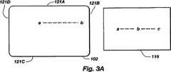
次に、第3A図−第3C図を参照して、本発明のドラグ拡張機能について説明する。第3A図は、ここではトップエッジ121A、ライトエッジ121B、ボトムエッジ121C、およびレフトエッジ121Dと呼ぶ、4つのエッジ121A−Dを有するタッチパッド102を示す。図示するタッチパッド102は本発明に使用するのに好ましいものではあるが、さまざまな形状および構成のタッチパッドを使用することができる。さらに、タブレットおよび前記した典型的な装置等の、他のカーソルロケーティング装置にも本発明は有利である。
第3A図にはディスプレイ116も図示されている。本発明のこの例では、タッチパッド102は相対カーソルロケーティングデバイスとして働く。ディスプレイ116内に3つのカーソル位置a,b,cがある。カーソル位置aは開始カーソル位置を表す。カーソル位置cは所望の終止カーソル位置を表す。タッチパッド102上で、位置aはスタイラスやユーザの指等のポインティング対象の開始位置、およびユーザがテキストや他の対象をディスプレイ上の所望位置cへ動かすためのドラグ操作を開始する位置を表す。タッチパッドは相対カーソル位置決め装置として使用されるため、残念ながら、ユーザがタッチパッド102のライトエッジ121Bの位置bへポインティングオブジェクトを動かした時、カーソルはディスプレイ116上の対応する位置bへしか到達しない。次に、ユーザはタッチパッド102の表面からポインティングオブジェクトを引き上げなければならず、本発明に依らない場合、それによりドラグ操作は終止する。ポインティング対象を引き上げることにより、カーソルは開始位置aへ素早く戻ってしまうことさえある。ポインティングオブジェクトは第3A図−第3C図に明示されてはいないが、ユーザの指や任意他の適切なオブジェクトとすることができる。
次に、さらにタッチパッド102を示す第3B図を参照する。本発明に従って、タッチパッド102の各エッジ121A−Dに隣接して境界領域120A−Dが画定される。境界領域120A−Dの各限界は線122A−Dで表される。従来技術でお判りのように、タッチパッド102上の任意の位置をx,y座標により規定することができ、第3B図からお判りのように、いずれも正の値で表される。要約すると、本発明のタッチパッド102はその表面上にポインティングオブジェクトが存在するかどうかを確認する垂直z成分も与えることが好ましい。本発明は、タッチパッド102の表面上を適切に“タップ”して提供すべきクリックおよびドラグ機能を引き起こすポインティングオブジェクトを利用することが好ましい。このような“タップ”機能を実施するのに使用できるz位置情報が米国特許第5,305,017号に記載されているが、本発明の範囲内で、機械的もしくはタッチ感知ボタン等の、代替方法を使用してクリックおよびドラグ機能へアクセスすることができる。
次に、本発明の好ましい実施例と共に作動するタッチパッド102およびディスプレイ116を表す第3C図を参照する。さらに詳しく説明するように、本発明の作動中にユーザがディスプレイ116上で位置aから位置cへカーソルを動かしたい場合、ユーザはドラグモードとすることによりタッチパッド102上のポインティング対象の動きを位置aで開始する。ユーザがポインティングオブジェクトを境界102B内の位置bへ動かすと、ユーザがタッチパッド102の表面からポインティングオブジェクトを引き上げている間ドラグモードが維持される(それにより、カーソルはディスプレイ116上の位置bに保持される)。ユーザはポインティングオブジェクトをタッチパッド102上の新しい位置、例えば、位置bnewへ動かし、タッチパッド102の所望の方向のストロークを継続する。ディスプレイ116上の位置bに保持されたカーソルはディスプレイ116上の所望のカーソル位置cへ動き続ける。カーソルが位置cに達すると、ユーザは前記したようにドラグ機能を解除する。ドラグ機能の解除により、例えば、テキストや対象(第3C図には図示せず)を位置cにおいてドロップさせることができる。
最も有益なことは、本発明により、ユーザは境界120A−D内を含むタッチパッド102上のどこででもポインティングオブジェクトを再位置決めして、任意の方向でドラグ操作を継続できることである。さらに、本発明により、ユーザは境界120A−Dへ入るたびにドラグモードを維持しながら、タッチパッド102を横切するマルチプルストロークを利用することができる。したがって、(非常に正確なカーソルロケーティングを行うために)ディスプレイ116を横切するのにタッチパッド102の表面を横切する多くのストロークを必要とするようにタッチ感知ポインティングデバイス100の出力がスケールされている場合には、カーソルがディスプレイ116をゆっくり横切する時に中断することなく、ユーザはドラグモードとされている間にタッチパッドを繰り返しストロークすることができる。さらに、文書や広げた用紙が大きすぎて一時に小部分しかディスプレイ116上にウィンドすることができない場合には、ドラグモードを維持しながらタッチパッド102を横切する本発明のマルチプルストロークの特徴は非常に有益となる。
前記したように、本発明により、ユーザはこれまでに知られていないもしくは示唆されていない方法で有利にコンピュータポインティングデバイスのドラグ機能を拡張することができる。本発明により、ユーザは、方法や装置に対する長期の練習すなわち習熟期間を必要とせずに、容易に、簡便にドラグ機能を拡張することができる。
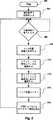
次に、本発明に従って実施される基本的ステップを示すフロー図である第4図を参照する。第4図のフロー図は150で開始され本発明のつの好ましい方法を示す。境界領域はステップ152で規定される。ステップ154において、タッチパッド102および付属構造により、ポインティングオブジェクトが境界120A−D内となる時が検出される。当業者ならばポインティングオブジェクトが境界上、境界付近、もしくは境界内にある時を確認するさまざまな方法がお判りであろう。
ステップ156において、ドラグ機能が関与しているかどうか確認される。ドラグ機能が関与しており(ステップ156)、ポインティングオブジェクトが境界内であれば(ステップ154)、本発明に従いかつステップ158に示すように、ドラグモードが維持されカーソルは第1の位置に保持される。説明の都合上、第1の位置はポインティングオブジェクトがタッチパッド102から引き上げられた時のディスプレイ上のカーソルの位置である。ユーザがポインティングオブジェクトをタッチパッド102上の別の位置へ動かしている間、ドラグモードは維持されカーソルはディスプレイ(第3A図−第3C図の116)上の第1の位置に保持される。ステップ160において、ユーザがポインティングオブジェクトをタッチパッド102上の新しい位置から終端位置まで動かす時に、カーソルはディスプレイ116上を動き続けるようにドラグ機能が継続される。ここでは、終端位置はディスプレイ116上のカーソルの所望位置に対応する。
ドラグモードを維持しながら、ユーザがポインティングオブジェクトを位置感知面上の別の位置へ再位置決めしている間カーソルをリアルタイムディスプレイ上の位置に保持し、次に、ユーザがポインティング対象の動きを続ける時にディスプレイ上の位置からのカーソルの動きを継続できるようにする任意の方法もしくは構造は、本発明の範囲内に入るものとする。
次に、本発明の好ましい実施例に関する情報をさらに提供する第5図−第8図を参照する。当業者ならば、ここに記載された情報を使用して、本発明を実施するためのソフトウェア・ファームウェア、および/もしくはハードウェアのさまざまな構造を容易に考えられるものと思われる。
開始162で始まる第5図のフロー図において、境界限界(第3B図の122A−D)が初期化される。望ましくは、境界限界(122A−D)の位置はユーザが変えることができ、各境界限界(122A−D)はユーザが異なるように初期化することができる。タッチパッド102(第3B図の116)上のどこででも境界(第3B図のサイズおよび位置を決め、ユーザのニーズおよび要望に従って任意の形状およびサイズの境界を作り出すことは本発明の範囲内に入る。
ステップ166において、タッチパッド(第3A図−第3C図の102)や他の位置感知装置から位置情報が得られるまで、本方法はループで待機する。タッチパッド102からの位置情報が得られると、ステップ168において、x,y,z位置情報が処理される。本発明では、クリックおよびドラグ機能はユーザがタッチパッド102の表面をタップして引き出されることが最も好ましい。最も好ましい実施例では、本発明により、ユーザは1度タップしてクリック機能を引き出し、2度タップしてダブルクリック機能を引き出し、1度タップした後ですぐにタッチパッド(第3A図−第3C図の102)の表面に対してポインティングオブジェクトを保持することによりドラグ機能を引き出すことができる。ユーザが境界(第3B図の120A−D)の外側でポインティングオブジェクトをタッチパッド(第3A図−第3C図の102)から引き上げると、ドラグモードが終止する。ステップ170において、ドラグモードが関与しているかどうか確認される。ドラグモードとされているかまたドラグモードを継続すべきかを確認かるのに使用するステップに関する情報がさらに第6図に記載されており、それについて簡単に説明する。
第7図に関してさらに説明するように、次に、ステップ172において、本方法によりポインティングオブジェクトが境界(第3B図の120A−D)内にあるかどうかが確認される。第8図に関してさらに説明するように、ステップ174において、ドラグ拡張モードが起動される。次に、ステップ176において、x,y,zおよびボタン情報がコンピュータ116へ送られ、例えば、コンピュータ112内に常駐するマウスドライバ114により処理される。次に、本方法はステップ166へループバックして処理を継続する。
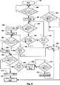
次に、第6図のフロー図を参照して、第5図のステップ170で前記したようにドラグモードが関与しているかどうかを確認するための最も好ましい方法について説明する。178で開始して、本方法により、ステップ180においてポインティングオブジェクトがタッチパッド(第3A図−第3C図の102)上にあるかどうかが確認される。ポインティングオブジェクトがタッチパッド102上にある場合には、ステップ182においてタイマが設定される。タイマの長さはユーザが変えてさまざまな選択をすることができる。ステップ184において、本方法によりポインティングオブジェクトがタッチパッド102から離されているかどうかが確認される。ポインティングオブジェクトがタッチパッド102から離されていない場合には、本方法はステップ190へ進みポインティングオブジェクトがタッチパッド102上を動いたかどうかが確認される。ポインティングオブジェクトがタッチパッド102上を動いていない場合には、ステップ192において、本方法によりタイマがタイムアウトしたかどうかが確認される。ステップ192においてタイマがタイムアウトしておれば、本方法はステップ184へ戻り、ステップ192においてタイマがタイムアウトしていなければ、本方法はステップ200へ進みそこでボタンアップ信号が設定される。また、ステップ190においてポインティングオブジェクトが動いておれば、本方法はやはりステップ200へ進みそこでボタンアップ信号が設定される。
再びステップ184へ戻って、ポインティングオブジェクトがタッチパッドから離されておれば、ステップ186において、本方法によりボタンダウン信号が設定されステップ188においてタイマが設定される。ステップ196において、本方法によりポインティングオブジェクトがタッチパッド(第3A図−第3C図の102)上にあるかどうかが確認される。ポインティングオブジェクトがタッチパッド102上にあれば、ステップ198において、本方法によりタイマ(ステップ18)がタイムアウトしているかどうかが確認され、ステップ198においてタイマがタイムアウトしていなければ、本方法はステップ196へループバックする。タイマ(ステップ188)がタイムアウトしておれば、本方法はステップ200へ進む。
ステップ196において、ポインティングオブジェクトがタッチパッド(第3A図−第3C図の102)上にあることが確認されると、本方法はステップ202へ進んでタイマを設定する。ステップ202の後で、本方法はステップ204へ進んでポインティングオブジェクトがタッチパッド102から離されているかどうかを確認し、離されておれば、本方法はボタンダウンルーチンを設定し(ステップ216)、設定したボタンダウンルーチンを進み(ステップ216)、次に、ステップ200へ進んでボタンアップ信号を設定する。
ステップ204において、ポインティングオブジェクトがタッチパッド(第3A図−第3C図の102)から離されていないことが確認されると、本方法はステップ206へ進み、ステップ202で設定されたタイマがタイムアウトしているかどうかが確認される。ステップ206において、タイマがタイムアウトしていなければ、本方法はステップ204へループバックする。ステップ206において、タイマがタイムアウトしておれば、本方法はステップ208へ進んでドラグモードとされる。ステップ210において、本方法によりポインティングオブジェクトがタッチパッド102から離されているかどうかが確認される。ポインティングオブジェクトがタッチパッド102から離されていなければ、本方法はステップ210のループで待機する。ポインティングオブジェクトがタッチパッド102から離されておれば、本方法はステップ212へ進みそこでset no dr agルーチンが実行されそれにはボタンアップ信号を設定するステップ200が続く。ステップ200から、本方法によりポインティングオブジェクトがタッチパッド102から離されているかどうかが再度確認される。ポインティングオブジェクトがタッチパッド102から離されていなければ、ステップ194において、本方法はループバックして待機する。ポインティングオブジェクトがタッチパッド102から離されておれば、本方法はステップ18わへ戻る。前記した方法により、ユーザは1本の指もしくは他の適切なポインティングオブジェクトでタップすることにより簡便にクリック機能を実行しドラグ機能に関与することができる。
本発明により産業標準マウスドライバ(第2図の114)に必要でマウスデバイスをエミュレートする信号が与えられることがお判りであろう。また、本発明は現在利用可能なもしくは将来利用可能となる他のさまざまな方法によりコンピュータ(第2図の112)と通信することができる。また、最も好ましくは、本発明によりユーザはいかなるボタンも押すことなく、クリック操作を実行できるだけでなくドラグモードと関与することができる。それでも、クリックおよびドラグ機能を引き出して関与するのにボタンが必要か否かに拘わらず、本発明により従来タッチ感知ポインティングデバイスでは利用できない利点が得られる。
次に、第7図を参照する。第7図は、第5図のステップ172において前記したように、ポインティングオブジェクトが境界(第3B図の120A−D)内にあるかどうかを確認する本発明の好ましい方法を示すフロー図である。230で開始して、本方法によりドラグモードとされているかどうかがステップ232で確認される。ドラグモードとされていなければ、ステップ242において、set no at edgeフラグが実行されステップ248において本方法はエグジットする。
ステップ232においてドラグモードされると、本方法によりポインティングオブジェクトのx位置がレフトリミット122Dよりも小さいかどうか(ステップ234)、ポインティングオブジェクトのy位置がボトムリミット122Cよりも大きいかどうか(ステップ236)、ポインティングオブジェクトのx位置がライトリミット122Bよりも大きいかどうか(ステップ238)、あるいはポインティングオブジェクトのy位置がトップリミット122Aよりも小さいかどうかが確認され、次に、本方法はステップ244へ進んでat edgeフラグが設定され、ステップ248においてエグジットする。本方法によりポインティングオブジェクトのx位置がレフトリミット122Dよりも小さくない(ステップ234)、ポインティングオブジェクトのy位置がボトムリミット122Cよりも大きくない(ステップ236)、ポインティングオブジェクトのx位置がライトリミット122Bよりも大きくない(ステップ238)、あるいはポインティングオブジェクトのy位置がトップリミット122Aよりも小さくないことが確認されると、本方法はステップ246へ進んでnot at edgeフラグが設定され、ステップ248においてエグジットする。前記したように、本発明の方法によりポインティングオブジェクトが境界内にあるかどうかが効率的に確認される。
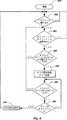
次に、第8図を参照する。第8図はタッチ感知ポインティングデバイス100の位置感知面のエッジを越えてドラグモードを拡張するための好ましい方法を示すフロー図であり、第5図のステップ174に示したドラグ拡張ルーチンの例である。第8図の250で開始して、本方法により、最初にステップ252においてドラグモードとされているかどうかが確認される。ドラグモードとされておれば、本方法はステップ252においてループで待機する。ドラグモードとされておれば、本方法により、次に、ポインティングオブジェクトが境界(第3B図の120A−D)内にあるかどうかが確認される。ポインティングオブジェクトが境界内になければ、本方法はステップ252へ戻る。ステップ254において、ポインティングオブジェクトが境界内にあることが確認されると、本方法により、ステップ256においてポインティングオブジェクトがタッチパッド102から離されているかどうかが確認される。ポインティングオブジェクトがタッチパッド102から離されていなければ、本方法はステップ254へ戻る。ステップ256において、ポインティングオブジェクトがタッチパッドから離されておれば、本方法はステップ258へ進みそこでドラグ信号が設定されかつタイマが設定される。ここでは、タイマは好ましくは2秒に設定されるが、ユーザの要望に合わせて調整することができる。
第6図−第8図に関して説明した全てのタイマの期間をユーザが調整できることが好ましい。ステップ258で設定されるタイマの期間により、第3C図に関して説明したように、ユーザは1つの境界120A−Dからタッチパッド102上の新しい位置までどれだけ長くポインティングオブジェクトを動かさなければならないかが決定される。ステップ258の後で、本方法によりポインティングオブジェクトがタッチパッド102上にあるかどうかが確認され、ある場合には、本方法はステップ254へ戻る。ステップ260において、ポインティングオブジェクトがタッチパッド102上に無いことが確認されると、本方法はステップ262へ進みそこでタイマ(ステップ258)がタイムアウトしているかどうかが確認される。ステップ262において、タイマがタイムアウトしていなければ、本方法はステップ260へ戻る。ステップ262においてタイマがタイムアウトしておれば、本方法はステップ264へ進んでno drag信号が設定され、本方法はステップ252へ戻る。
前記したように、本発明の好ましい方法により、ユーザはタッチパッド102のエッジを越えてポインティングデバイスのドラグ機能を拡張することができる。本発明の1つの現在好ましいシステムを表すブロック図である第2図を再び参照する。前記したように、本発明の方法は多くの異なる装置およびシステムとして実施できることがお判りであろう。本発明が実施される応用に応じて、本発明をソフトウェア、ファームウェア、ハードウェア、もしくはそれらの組合せとして実施することができる。
第2図のインターフェイス回路104内に107で示されているのはタッチパッドを使用するのに必要な機能を実行する位置検出手段である。第2図には位置感知構造と協同して本発明を実施する構造も図示されている。当業者ならば、ここに記載した情報を使用して、任意数の現在利用可能なカーソルロケーティングデバイスおよび将来利用可能なカーソルロケーティングデバイスへの本発明の統合を、任意の部品の製作および任意の必要なプログラミングコードの生成を含めて、容易に達成できるものと思われる。
第2図の106に示されているのは、ポインティングデバイスがいつ境界のエッジ上に来るかもしくは越えるかを検出する手段である。108にドラグ機能を起動する手段も示されている。第2図の110にはドラグモードを維持しカーソルをディスプレイ上の第1の位置に保持する手段が示されている。第2図の109にはディスプレイ上の第1の位置から第2の位置へドラグ機能を継続する手段も示されている。前記した構造は多くの異なる形式、例えば、1個の集積回路として実施することができる。本発明の方法と同等な機能を実行するいかなる構造も本発明のシステムの範囲内に入るものとする。
前記したことから、本発明により、コンピュータポインティングデバイスのドラグ機能を拡張するための信頼できる使い易いシステムおよび方法が提供されることがお判りであろう。また、本発明により、特にタッチ感知ポインティングデバイスを使用するようにされ唯一のポインティングオブジェクトとしてユーザの指で操作することができる、コンピュータポインティングデバイスのドラグ機能を拡張するためのシステムおよび方法が提供される。
本発明は、その精神および本質的な特徴を逸脱することなく、他の特定の形式で実施することができる。説明した実施例はあらゆる点において説明用にすぎず制約的意味合いはない。したがって、本発明の範囲は前記説明ではなく請求の範囲によって示される。請求の範囲と同等の意味合いおよび範囲内に入る変更は全て請求の範囲に含まれるものとする。background
1. The present invention relates to a computer pointing device and control method used to control the movement of a cursor on a display. In particular, the present invention relates to touch sensitive input devices for inputting data to computers and other data utilization devices.
2.Background art
Computer input devices are known in the prior art. There are several types of input devices including the well-known “mouse” everywhere. When combined with a graphic user interface (GUI), the mouse is very popular because it is much easier to use than type keyboard commands. The mouse is accepted as a “user friendly” input device for both experienced and novice computer users. It is recognized that the popularity achieved by the mouse has promoted the explosive growth of the personal computer industry because the mouse provides a simple means for the user to enter data into the computer.
Although the mouse is currently the most popular non-keyboard input device, the mouse generally requires a freely rolling surface, ie a table top, that can be manipulated thereon. Unfortunately, mice are not well suited for use in tight spaces and portable computers, especially laptops, notebooks, sub-notebooks, and palmtop computers. In response to previous needs for simpler input devices suitable for both portable and desktop computers, a variety of alternative input devices have been proposed. Such alternative input devices include devices commonly referred to as trackballs, track pens, track point devices, as well as various devices that sense the position of a pointing object on a position sensitive surface. Devices that sense the position of a pointing object on a sensing surface are generally simple to use, easily integrated with current computers and other computing devices, reliable, rugged, It has the advantage of being compact and transportable to various locations.
Various types of input devices use position sensitive surfaces. Examples are described in the following patents. Rogers et al., U.S. Pat. No. 3,886,311 (a writing pen for detecting a time-varying electrostatic field generated from a writing tablet), Rogers et al. U.S. Pat. No. 4,672,154 (XY coordinate system) U.S. Pat. No. 4,680,430 to Yoshikawa et al. (On a plane displayed by touch of a fingertip or other load), a cordless stylus that emits a directional electric field from the tip of a conductive pen cartridge sensed by a digitizer tablet US Pat. No. 4,103,252 of Bobic et al. (Capacity generated by touch changing the time constant of the RC network that is part of the transmitter) A position sensing tablet having electrodes arranged at the boundary of a sensing region for detecting a human touch by a change in charge G. Matsutake, U.S. Pat. No. 4,736,191 (detecting a user touch on a dielectric layer superimposed on the plate by charging and discharging each sector in the individual conductive plate individually to determine the sector capacity increase) US Pat. No. 4,550,221 to Mabus et al. (Conversion of touch position into output signal, first and second interleaved, closely spaced non-overlapping) U.S. Pat. No. 4,639,720 to Rimpulse Key et al. (Transparent capacitive pixel with capacitive characteristics changing in response to a conductive chip stylus passing over the surface of the pad) An electronic sketch pad including a graphic input pad with an array), and European Patent Application No. 574,213 (horizontal and connected to a position sensing pad) Proximity sensor including a sensor matrix array which senses the change in capacitance between the straight conductor obtaining x, y, and z position information).
A particularly useful and advantageous input device is disclosed in Garheid US Pat. No. 5,305,017. The Garheid patent discloses devices and methods that overcome the disadvantages inherent in sensing tablets and other devices that utilize sensing surfaces. The device and method of the Garheid patent includes a touch sensitive input pad on which a user can conveniently input location information with a finger. In operation, the user's fingertip is brought close to the top surface of the position sensing surface of the touch sensing pad. The Garheid device detects not only the proximity of the finger in the z direction to the sensing surface, but also the position of the fingertip in the x and y directions of the touchpad. In addition to the finger, the pointing object can be any other conductive object.
The devices described above and devices that incorporate position sensitive tablets or sensing surfaces have inherent disadvantages when performing certain functions.
FIG. 1 shows a
In order to be compatible with the
Also shown in FIG. 1 is a touch-sensitive positioning device, generally at 26, which includes a position-
In order to be practically usable in a portable computer, the sensing surface of any touch-sensing device can be, for example, 2.54 cm x 5.08 cm (1 inch x 2 inches) to 7.62 cm x 12.7 cm (3 inches x 5 inches) Only a small
More typically, the touch sensing device is used as a relative cursor positioning device in which the cursor is moved across the display using one or several strokes across the
One solution to the problems associated with drag and drop operations when using touch sensitive input devices is described in US Pat. No. 5,327,161 to Logan et al. In the method described in Logan et al., When the
Summary and purpose of the invention
In view of the state of the prior art described above, the present invention aims to achieve the following objects and advantages.
It is a primary object of the present invention to provide a system and method for extending the drag function of a computer pointing device.
It is also an object of the present invention to provide a system and method for extending the drag function of a computer pointing device that can be easily remembered and implemented by a user.
It is another object of the present invention to provide a system and method that extends the drag and drop functionality of computer pointing devices that are specifically adapted to use touch sensitive pointing devices.
It is another object of the present invention to provide a system and method for extending the drag function of a computer pointing device that is well suited for using a touch sensitive pointing device that can be operated with a user's finger as the only pointing object. It is.
These and other objects and advantages of the present invention will become more fully apparent from the following description and appended claims, and may be learned by practice of the invention.
The present invention provides an advantageous method and system for extending the distance a user moves a cursor across a computer display device when using a pointing device. In particular, the present invention is advantageous when a touch sensitive pointing device is used as a relative cursor locating device that allows the user to move the cursor on the display by moving the stylus or finger on the position sensitive surface. is there. When using such a relative cursor locating device, it is often difficult or inconvenient to perform movement of text and objects that appear on a computer display. Such touch-sensitive pointing devices generally have a small position sensing surface, and when the user reaches the perimeter, the cursor does not move further on the display and the user stops the drag operation (so that the object is on the display). You must complete another drag operation by starting another movement on the position-sensitive surface.
In order to overcome this long-standing problem in the industry, the present invention delimits the outer periphery of the position sensing surface. Next, the method of the present invention detects when the pointing object enters the boundary on the position sensitive surface. Next, it is determined whether the user is performing a drag operation when the pointing device enters the boundary (ie, the drag function is involved). When the drag function is performed by the user, the drag mode is maintained by the present invention while the user moves the pointing device, i.e., the stylus or finger, to a new position that is not within the boundary on the position sensing surface. (The cursor is held at the position on the computer display when the pointing object enters the border). The user then continues the drag function from where the cursor on the computer display is held to the desired end position on the computer display when moving the pointing device from the new position to the end position on the position sensing surface.
Also preferably, the time during which the drag mode is maintained according to the present invention (i.e., the time during which the cursor is held while the user moves the pointing object) can be varied for the convenience of the user. Further, preferably, according to the present invention, the drag mode is maintained until an action of the user such as a drag function released by the user or a click function used by the user is performed.
Most preferably, the present invention is a touch sensitive pointing device that allows the user to emulate mouse click and drag functions by positioning the cursor on the computer display with one finger and tapping the position sensitive surface with the finger. Used.
[Brief description of the drawings]
For a better understanding of how the above and other advantages and objects of the present invention are achieved, the present invention will be described in more detail with reference to specific embodiments illustrated in the accompanying drawings. With the understanding that the drawings are only representative examples of the invention and are not intended to limit its scope, the invention will now be described more clearly and in detail using the accompanying drawings, wherein In addition,
FIG. 1 is a block diagram showing available computer pointing devices.
FIG. 2 is a block diagram representing the structure of a particular embodiment of the invention described herein.
3A-3C illustrate the operation of the embodiment of the invention described herein.
FIG. 4 is a flow diagram showing the basic steps performed in accordance with the present invention.
FIG. 5 is a flow diagram illustrating certain steps performed by the embodiments of the invention described herein.
FIG. 6 is a flow diagram illustrating the steps performed by the embodiment of the invention described herein to determine whether to enter drag mode.
FIG. 7 is a flow diagram illustrating steps performed in accordance with an embodiment of the invention described herein to determine if a user is moving a pointing object to a touch sensitive pad boundary.
FIG. 8 is a flow diagram illustrating the steps performed by the embodiments of the invention described herein to extend the drag mode beyond the edge of the position sensing surface.
Detailed Description of the Preferred Embodiment
Reference is now made to the drawings in which the same structure is provided with the same reference numerals.
Reference is now made to FIG. 2, which is a block diagram representing one preferred embodiment of the present invention. It will be appreciated that the invention may be practiced in specific forms other than those described herein. However, the described embodiment is the presently preferred embodiment for practicing the present invention.
FIG. 2 illustrates a touch
The touch sensitive pointing device described in US Pat. No. 5,305,017 is particularly preferred for use with the present invention. The touch-sensitive pointing device described in US Pat. No. 5,305,017 is particularly advantageous in that the cursor positioning, clicking and dragging functions can all be performed accurately by the user using only one finger as a pointing object. It is advantageous. Other advantages of the touch sensitive pointing device described in US Pat. No. 5,305,017 are described therein and will become apparent using the invention. US Pat. No. 5,305,017 is incorporated herein in its entirety as part of this disclosure. Using the information described in US Pat. No. 5,305,017 and the information described herein, one of ordinary skill in the art will readily be able to reach a system implementing the present invention. Importantly, the present invention is easily adaptable to various other pointing devices as described above.
The touch
Next, the drag extension function of the present invention will be described with reference to FIGS. 3A-3C. FIG. 3A shows a
A
Reference is now made to FIG. 3B which further shows the
Reference is now made to FIG. 3C representing the
Most usefully, the present invention allows the user to reposition the pointing object anywhere on the
As described above, the present invention allows a user to advantageously extend the drag function of a computer pointing device in a way that has not been previously known or suggested. According to the present invention, the user can easily and easily extend the drag function without requiring a long-term practice, that is, a learning period for the method or apparatus.
Reference is now made to FIG. 4, which is a flow diagram illustrating the basic steps performed in accordance with the present invention. The flow diagram of FIG. 4 starts at 150 and illustrates one preferred method of the present invention. The boundary region is defined at
In
While maintaining drag mode, hold the cursor in position on the real-time display while the user repositions the pointing object to another position on the position sensing surface, and then when the user continues to move the pointing object Any method or structure that allows the cursor to continue to move from a position on the display is intended to be within the scope of the present invention.
Reference is now made to FIGS. 5-8 which further provide information regarding the preferred embodiment of the present invention. Those skilled in the art will readily be able to contemplate various structures of software firmware and / or hardware for implementing the present invention using the information described herein.
In the flow diagram of FIG. 5 starting at
In
As described further with respect to FIG. 7, then in
Next, the most preferable method for confirming whether or not the drag mode is involved as described above in
Returning again to step 184, if the pointing object has been removed from the touchpad, then in
If it is determined in
If it is determined in
It will be appreciated that the present invention provides a signal emulating a mouse device that is necessary for an industry standard mouse driver (114 in FIG. 2). Also, the present invention can communicate with a computer (112 in FIG. 2) by various other methods that are currently available or will be available in the future. Also, most preferably, the present invention allows the user not only to perform a click operation without pressing any buttons, but also to engage with the drag mode. Nevertheless, whether or not a button is required to extract and participate in the click and drag functions, the present invention provides advantages not available with conventional touch sensitive pointing devices.
Reference is now made to FIG. FIG. 7 is a flow diagram illustrating the preferred method of the present invention for ascertaining whether the pointing object is within the boundary (120A-D in FIG. 3B) as previously described in
When the drag mode is set in
Reference is now made to FIG. FIG. 8 is a flow diagram illustrating a preferred method for extending the drag mode beyond the edge of the position-sensitive surface of the touch-
Preferably, the user can adjust the duration of all the timers described with respect to FIGS. The duration of the timer set at
As described above, the preferred method of the present invention allows the user to extend the drag function of the pointing device beyond the edge of the
Illustrated at 106 in FIG. 2 is a means for detecting when the pointing device is on or beyond the boundary edge. A means for activating the drag function is also shown at 108. 110 of FIG. 2 shows means for maintaining the drag mode and holding the cursor in the first position on the display. 109 in FIG. 2 also shows means for continuing the drag function from the first position to the second position on the display. The structure described above can be implemented in many different forms, for example as a single integrated circuit. Any structure that performs a function equivalent to the method of the present invention shall fall within the scope of the system of the present invention.
From the foregoing, it will be appreciated that the present invention provides a reliable and easy-to-use system and method for extending the drag function of a computer pointing device. The present invention also provides a system and method for extending the drag function of a computer pointing device that is specifically adapted to use a touch sensitive pointing device and can be operated with a user's finger as the only pointing object. .
The present invention may be implemented in other specific forms without departing from its spirit and essential characteristics. The described embodiments are merely illustrative in all respects and are not limiting. The scope of the invention is, therefore, indicated by the appended claims rather than by the foregoing description. All changes that fall within the meaning and range of equivalency of the claims are to be embraced within their scope.
Claims (20)
Translated fromJapaneseユーザにより操作されるポインティング・オブジェクトが移動できる最大距離よりも短い境界領域を画定するステップと、
ポインティング・オブジェクトが境界のエッジ上にあるかそれを越える時を検出するステップと、
ポインティング・オブジェクトが境界へ入る時にドラグ機能が関与しているかどうかを確認するステップと、
ポインティング・オブジェクトがそのドラグ位置から離れる時にドラグ機能を維持するステップと、
ポインティング・オブジェクトがポインティング・デバイスを使用して新しい位置へ動かされている間、ドラグ機能を維持しカーソルを計算出力装置上の第1の位置に保持するステップと、
ポインティング・オブジェクトがドラグ位置へ再度あてがわれる時にドラグ機能を継続するステップと、
ポインティング・オブジェクトが新しい位置から終端位置へ動かされる時に、計算出力装置上の第1の位置から計算出力装置上の第2の位置へのドラグ機能を継続するステップと、
を含む前記方法。A method to extend thecursor drag functionpointing device that is used to control cursor movement on computing output device,the method comprising
A step ofpointing object defines a shorter border area than the maximum distance that can be moved to be operated by a user,
Detecting when thepointing object exceeds it or on the boundary edge,
Comprising the steps of drag function to check whether the involved when thepointing object enters the boundary,
Maintaining the drag function when thepointing object leaves its drag position;
A step of holding between, in the first position the calculated output device the cursor maintains a drag function of a pointingobject is being moved by using thepointing device to a new position,
Continuing the drag function when thepointing object is reassigned to the drag position;
When the pointingobject is moved from the new position to the end position, and continuing to drag function from a first position on the computing output device to a second location on the computing output device,
Including said method.
ポインティング・オブジェクトが別の新しい位置へ動かされている間、ドラグ機能を維持しカーソルを計算出力装置上の第1または第2の位置と異なる第3の位置に保持するステップと、
ポインティング・オブジェクトが別の新しい位置から最終位置へ動かされる時に、計算出力装置上の第3の位置から計算出力装置上の第4の位置へのドラグ機能を継続するステップと、
を含む前記方法。The method of claim 1, further comprising:
A step of holding between, thedifferent third positionand the first or second position on the computing output device the cursor maintains a drag function of a pointingobject is being moved to another new position,
When the pointingobject is moved to the final position from another new position, and continuing to drag function from the third position on the computing output device to the fourth position on the computing output device,
Including said method.
カーソルを所定期間、第1の位置に保持するステップと、
ドラグ機能が解除されるまでカーソルを第1の位置に保持するステップと、
クリック機能が起動されるまでカーソルを第1の位置に保持するステップと、
から選択される少なくとも1つのステップを含む前記方法。The method of claim 1, wherein the step of holding the cursor in the first position comprises:
Predetermined periodcursor, and the step of holding the first position,
Holding the cursor in the first position until the drag function is released;
Holding the cursor in the first position until the click function is activated;
It said method comprising at least one step selected from.
最大距離内の第1の距離に第1の境界を画定するステップと、
第1の距離を変えるステップと、
最大距離内の第2の距離に第1の境界に隣接して第2の境界を画定するステップと、
第2の距離を変えるステップと、
最大距離内の第3の距離に第2の境界に隣接して第3の境界を画定するステップと、
第3の距離を変えるステップと、
最大距離内の第4の距離に第3の境界に隣接して第4の境界を画定するステップと、
第4の距離を変えるステップと、
を含む前記方法。The method of claim 1, wherein the step of defining a boundary comprises:
Defining a first boundary at a first distance within a maximum distance;
Changing the first distance;
Defining a second boundary adjacent to the first boundary at a second distance within a maximum distance;
Changing the second distance;
Defining a third boundary adjacent to the second boundary at a third distance within a maximum distance;
Changing the third distance;
Defining a fourth boundary adjacent to the third boundary at a fourth distance within a maximum distance;
Changing the fourth distance;
Including said method.
位置感知面の周辺内に境界を画定するステップと、
ポインティング・オブジェクトが位置感知面の境界へ入る時を検出するステップと、
ポインティング・オブジェクトが境界へ入る時にドラグ機能がカーソルに対してアクティブであるかどうかを確認するステップと、
ポインティング・オブジェクトが位置感知面から離される時にドラグ機能を維持するステップと、
ポインティング・オブジェクトが新しい位置へ動かされている間、ポインティング・オブジェクトが境界へ入った時のカーソルの位置であるディスプレイ上の第1の位置にカーソルを保持するステップと、
ポインティング・オブジェクトが再度位置感知面へあてがわれる時にカーソルのドラグ機能を継続するステップと、
ポインティング・オブジェクトが位置感知面上の新しい位置から終端位置へ動かされる時にディスプレイ装置上の第1の位置から第2の位置へのドラグ機能を継続するステップと、
を含む前記方法。And transected display device responsive in real time to a user input to a method for a user to extend the distance that can move the cursor, the userutilizes apointing object position by the position sensing surfacehaving a peripheral is sensed ,
Defining a boundary within the periphery of the position sensing surface;
Detecting when thepointing object enters the boundary position sensing surface,
Comprising the steps of drag function to check whether it is active against the cursor when thepointing object enters the boundary,
And maintaining a drag function when thepointing object is released from the position sensing surface,
A step of holding between the cursor to the first position on the display the position of the cursor when thepointing object has entered the boundary pointingobject is being moved to a new position,
And continuing to drag function of the cursor when thepointing object is Ategawa to the position sensing surface again,
And continuing to drag function from a first location on the display device to a second position when thepointing object is moved from the new position on the position sensing surface to the end position,
Including said method.
カーソルを所定期間、第1の位置に保持するステップと、
ドラグ機能が解除されるまでカーソルを第1の位置に保持するステップと、
クリック機能が起動されるまでカーソルを第1の位置に保持するステップと、
から選択される少なくとも1つのステップを含む前記方法。The method of claim 10, wherein holding the cursor in the first position comprises:
Predetermined periodcursor, and the step of holding the first position,
Holding the cursor in the first position until the drag function is released;
Holding the cursor in the first position until the click function is activated;
It said method comprising at least one step selected from.
最大距離内の第1の距離に第1の境界を画定するステップと、
第1の距離を変えるステップと、
最大距離内の第2の距離に第1の境界に隣接して第2の境界を画定するステップと、
第2の距離を変えるステップと、
最大距離内の第3の距離に第2の境界に隣接して第3の境界を画定するステップと、
第3の距離を変えるステップと、
最大距離内の第4の距離に第3の境界に隣接して第4の境界を画定するステップと、
第4の距離を変えるステップと、
を含む前記方法。The method of claim 10, wherein the step of defining a boundary comprises:
Defining a first boundary at a first distance within a maximum distance;
Changing the first distance;
Defining a second boundary adjacent to the first boundary at a second distance within a maximum distance;
Changing the second distance;
Defining a third boundary adjacent to the second boundary at a third distance within a maximum distance;
Changing the third distance;
Defining a fourth boundary adjacent to the third boundary at a fourth distance within a maximum distance;
Changing the fourth distance;
Including said method.
周辺を有し、その上のポインティング・オブジェクトの位置を感知する感知面手段と、
ポインティング・オブジェクトが感知面手段上の周辺から境界距離内にある時を検出する手段と、
ユーザの連続ドラグ行動により関与されるカーソルのドラグ機能を起動させる手段と、
ポインティング・オブジェクトが感知面手段上の新しい位置へ動かされている間、ポインティング・オブジェクトが感知面上の周辺から境界距離内にある時にカーソルをディスプレイ上の第1の位置に保持しユーザがドラグ行動を中止する手段と、
ポインティング・オブジェクトが感知面手段上の新しい位置から終端位置まで動かされる時に、ユーザがディスプレイ上の第1の位置から第2の位置へのドラグ行動を継続するまでドラグ機能を維持する手段と、
を含む前記システム。A system that extends thecursor drag functionpointing device that is used to control cursor movement on display,the systemcomprising:
It has a peripheral, a sensing surface means for sensing the position of the pointingobject thereon,
Means forpointing the object to detect when there from the periphery of the sensing surface means in the boundary distance,
Means for activating the drag function of the cursor involved by the continuous drag action of the user;
Whilepointing object is being moved to a new position on the sensing surface means, the holding and the user drag action the cursor to the first position on the display when in the neighborhood of thepointing object sensing surface within the boundary distance Means to cancel
When the pointingobject is moved from the new position on the sensing surface means to the end position, and means for maintaining a drag function until the user continues to drag action from a first location on the display to the second position,
Including said system.
マウス・ドライバ手段と、
感知面手段をマウス・ドライバ手段とインターフェイスさせる手段と、
マウス・ドライバ手段および他の入力装置から受信する情報を処理するコンピュータ手段と、
コンピュータ手段に接続されて、マウス・ドライバにより指示される位置にカーソルをリアルタイムで表示するディスプレイ手段と、
を含む前記システム。The system of claim 16, further comprising:
Andmouse driver means,
A means formouse driver means and interfaces the sensing surface means,
And computer means for processing the information received from themouse driver means and other input devices,
Is connected to the computer means, and a display means for displaying a cursor in real-time position indicated by themouse driver,
Including said system.
Applications Claiming Priority (3)
| Application Number | Priority Date | Filing Date | Title |
|---|---|---|---|
| US08/413,199 | 1995-03-27 | ||
| US08/413,199US5757368A (en) | 1995-03-27 | 1995-03-27 | System and method for extending the drag function of a computer pointing device |
| PCT/US1996/004244WO1996030890A1 (en) | 1995-03-27 | 1996-03-27 | System for extending the drag function |
Publications (2)
| Publication Number | Publication Date |
|---|---|
| JPH11509944A JPH11509944A (en) | 1999-08-31 |
| JP3833709B2true JP3833709B2 (en) | 2006-10-18 |
Family
ID=23636266
Family Applications (1)
| Application Number | Title | Priority Date | Filing Date |
|---|---|---|---|
| JP52963996AExpired - Fee RelatedJP3833709B2 (en) | 1995-03-27 | 1996-03-27 | Drag function expansion system |
Country Status (5)
| Country | Link |
|---|---|
| US (1) | US5757368A (en) |
| JP (1) | JP3833709B2 (en) |
| AU (1) | AU5376896A (en) |
| DE (1) | DE19681316T1 (en) |
| WO (1) | WO1996030890A1 (en) |
Families Citing this family (146)
| Publication number | Priority date | Publication date | Assignee | Title |
|---|---|---|---|---|
| US5880411A (en)* | 1992-06-08 | 1999-03-09 | Synaptics, Incorporated | Object position detector with edge motion feature and gesture recognition |
| JP3280559B2 (en)* | 1996-02-20 | 2002-05-13 | シャープ株式会社 | Jog dial simulation input device |
| US6867790B1 (en)* | 1996-08-09 | 2005-03-15 | International Business Machines Corporation | Method and apparatus to conditionally constrain pointer movement on a computer display using visual cues, controlled pointer speed and barriers on the display which stop or restrict pointer movement |
| US5910802A (en)* | 1997-06-11 | 1999-06-08 | Microsoft Corporation | Operating system for handheld computing device having taskbar auto hide |
| GB9722766D0 (en) | 1997-10-28 | 1997-12-24 | British Telecomm | Portable computers |
| US6188391B1 (en) | 1998-07-09 | 2001-02-13 | Synaptics, Inc. | Two-layer capacitive touchpad and method of making same |
| JP2000122808A (en)* | 1998-10-19 | 2000-04-28 | Fujitsu Ltd | Input processing method and input control device |
| JP3449291B2 (en)* | 1999-05-14 | 2003-09-22 | 株式会社デンソー | Map display device |
| US6727892B1 (en) | 1999-05-20 | 2004-04-27 | Micron Technology, Inc. | Method of facilitating the selection of features at edges of computer touch screens |
| US6411283B1 (en)* | 1999-05-20 | 2002-06-25 | Micron Technology, Inc. | Computer touch screen adapted to facilitate selection of features at edge of screen |
| US6757002B1 (en) | 1999-11-04 | 2004-06-29 | Hewlett-Packard Development Company, L.P. | Track pad pointing device with areas of specialized function |
| KR20010046646A (en)* | 1999-11-15 | 2001-06-15 | 차종근 | Touch-Pad Operating Mouse Button |
| US7818691B2 (en)* | 2000-05-11 | 2010-10-19 | Nes Stewart Irvine | Zeroclick |
| US8103496B1 (en) | 2000-10-26 | 2012-01-24 | Cypress Semicondutor Corporation | Breakpoint control in an in-circuit emulation system |
| US8160864B1 (en) | 2000-10-26 | 2012-04-17 | Cypress Semiconductor Corporation | In-circuit emulator and pod synchronized boot |
| US8176296B2 (en) | 2000-10-26 | 2012-05-08 | Cypress Semiconductor Corporation | Programmable microcontroller architecture |
| US7765095B1 (en) | 2000-10-26 | 2010-07-27 | Cypress Semiconductor Corporation | Conditional branching in an in-circuit emulation system |
| US8149048B1 (en) | 2000-10-26 | 2012-04-03 | Cypress Semiconductor Corporation | Apparatus and method for programmable power management in a programmable analog circuit block |
| US6724220B1 (en) | 2000-10-26 | 2004-04-20 | Cyress Semiconductor Corporation | Programmable microcontroller architecture (mixed analog/digital) |
| US6897853B2 (en)* | 2000-11-10 | 2005-05-24 | Microsoft Corp. | Highlevel active pen matrix |
| JP3909230B2 (en)* | 2001-09-04 | 2007-04-25 | アルプス電気株式会社 | Coordinate input device |
| US7406674B1 (en) | 2001-10-24 | 2008-07-29 | Cypress Semiconductor Corporation | Method and apparatus for generating microcontroller configuration information |
| US8095879B2 (en) | 2002-12-10 | 2012-01-10 | Neonode Inc. | User interface for mobile handheld computer unit |
| US8078970B1 (en) | 2001-11-09 | 2011-12-13 | Cypress Semiconductor Corporation | Graphical user interface with user-selectable list-box |
| US8042093B1 (en) | 2001-11-15 | 2011-10-18 | Cypress Semiconductor Corporation | System providing automatic source code generation for personalization and parameterization of user modules |
| US7774190B1 (en) | 2001-11-19 | 2010-08-10 | Cypress Semiconductor Corporation | Sleep and stall in an in-circuit emulation system |
| US7770113B1 (en) | 2001-11-19 | 2010-08-03 | Cypress Semiconductor Corporation | System and method for dynamically generating a configuration datasheet |
| US8069405B1 (en) | 2001-11-19 | 2011-11-29 | Cypress Semiconductor Corporation | User interface for efficiently browsing an electronic document using data-driven tabs |
| US7844437B1 (en) | 2001-11-19 | 2010-11-30 | Cypress Semiconductor Corporation | System and method for performing next placements and pruning of disallowed placements for programming an integrated circuit |
| US6971004B1 (en) | 2001-11-19 | 2005-11-29 | Cypress Semiconductor Corp. | System and method of dynamically reconfiguring a programmable integrated circuit |
| US8103497B1 (en) | 2002-03-28 | 2012-01-24 | Cypress Semiconductor Corporation | External interface for event architecture |
| US7308608B1 (en) | 2002-05-01 | 2007-12-11 | Cypress Semiconductor Corporation | Reconfigurable testing system and method |
| WO2004057439A2 (en)* | 2002-05-31 | 2004-07-08 | University Of Utah Research Foundation | System and method for visual annotation and knowledge representation |
| US7761845B1 (en) | 2002-09-09 | 2010-07-20 | Cypress Semiconductor Corporation | Method for parameterizing a user module |
| US7454707B2 (en)* | 2002-09-30 | 2008-11-18 | Canon Kabushiki Kaisha | Image editing method, image editing apparatus, program for implementing image editing method, and recording medium recording program |
| US20050030048A1 (en)* | 2003-08-05 | 2005-02-10 | Bolender Robert J. | Capacitive sensing device for use in a keypad assembly |
| JP4574194B2 (en)* | 2004-03-05 | 2010-11-04 | 任天堂株式会社 | Game program |
| US7295049B1 (en) | 2004-03-25 | 2007-11-13 | Cypress Semiconductor Corporation | Method and circuit for rapid alignment of signals |
| KR20070011391A (en)* | 2004-04-23 | 2007-01-24 | 서크 코퍼레이션 | Improved methods for scrolling and edge motion on the touchpad |
| US20050283727A1 (en)* | 2004-06-21 | 2005-12-22 | Large William T | Non-resident methods and systems for providing clickless user actuation of a webpage |
| US8281241B2 (en) | 2004-06-28 | 2012-10-02 | Nokia Corporation | Electronic device and method for providing extended user interface |
| US20060007174A1 (en)* | 2004-07-06 | 2006-01-12 | Chung-Yi Shen | Touch control method for a drag gesture and control module thereof |
| JP4471761B2 (en)* | 2004-07-26 | 2010-06-02 | 任天堂株式会社 | GAME PROGRAM, GAME DEVICE, AND INPUT DEVICE |
| JP3734819B1 (en)* | 2004-07-26 | 2006-01-11 | 任天堂株式会社 | GAME PROGRAM, GAME DEVICE, AND INPUT DEVICE |
| US8286125B2 (en) | 2004-08-13 | 2012-10-09 | Cypress Semiconductor Corporation | Model for a hardware device-independent method of defining embedded firmware for programmable systems |
| US8069436B2 (en) | 2004-08-13 | 2011-11-29 | Cypress Semiconductor Corporation | Providing hardware independence to automate code generation of processing device firmware |
| US7332976B1 (en) | 2005-02-04 | 2008-02-19 | Cypress Semiconductor Corporation | Poly-phase frequency synthesis oscillator |
| US7400183B1 (en) | 2005-05-05 | 2008-07-15 | Cypress Semiconductor Corporation | Voltage controlled oscillator delay cell and method |
| US8089461B2 (en) | 2005-06-23 | 2012-01-03 | Cypress Semiconductor Corporation | Touch wake for electronic devices |
| US8050876B2 (en)* | 2005-07-18 | 2011-11-01 | Analog Devices, Inc. | Automatic environmental compensation of capacitance based proximity sensors |
| JP2007058785A (en)* | 2005-08-26 | 2007-03-08 | Canon Inc | Information processing apparatus and drag object operating method in the apparatus |
| US7307485B1 (en) | 2005-11-14 | 2007-12-11 | Cypress Semiconductor Corporation | Capacitance sensor using relaxation oscillators |
| US8085067B1 (en) | 2005-12-21 | 2011-12-27 | Cypress Semiconductor Corporation | Differential-to-single ended signal converter circuit and method |
| US7312616B2 (en) | 2006-01-20 | 2007-12-25 | Cypress Semiconductor Corporation | Successive approximate capacitance measurement circuit |
| US20070176903A1 (en)* | 2006-01-31 | 2007-08-02 | Dahlin Jeffrey J | Capacitive touch sensor button activation |
| US8139028B2 (en)* | 2006-02-01 | 2012-03-20 | Synaptics Incorporated | Proximity sensor and method for indicating extended interface results |
| US7770126B2 (en) | 2006-02-10 | 2010-08-03 | Microsoft Corporation | Assisting user interface element use |
| US20070097096A1 (en)* | 2006-03-25 | 2007-05-03 | Outland Research, Llc | Bimodal user interface paradigm for touch screen devices |
| US8067948B2 (en) | 2006-03-27 | 2011-11-29 | Cypress Semiconductor Corporation | Input/output multiplexer bus |
| US8144125B2 (en) | 2006-03-30 | 2012-03-27 | Cypress Semiconductor Corporation | Apparatus and method for reducing average scan rate to detect a conductive object on a sensing device |
| US7721609B2 (en) | 2006-03-31 | 2010-05-25 | Cypress Semiconductor Corporation | Method and apparatus for sensing the force with which a button is pressed |
| US8040142B1 (en) | 2006-03-31 | 2011-10-18 | Cypress Semiconductor Corporation | Touch detection techniques for capacitive touch sense systems |
| KR101327581B1 (en)* | 2006-05-24 | 2013-11-12 | 엘지전자 주식회사 | Apparatus and Operating method of touch screen |
| KR20070113018A (en)* | 2006-05-24 | 2007-11-28 | 엘지전자 주식회사 | Touch screen device and its execution method |
| KR101269375B1 (en)* | 2006-05-24 | 2013-05-29 | 엘지전자 주식회사 | Touch screen apparatus and Imige displaying method of touch screen |
| US20090213086A1 (en)* | 2006-04-19 | 2009-08-27 | Ji Suk Chae | Touch screen device and operating method thereof |
| KR20070113025A (en)* | 2006-05-24 | 2007-11-28 | 엘지전자 주식회사 | Touch screen device and its operation method |
| KR20070113022A (en) | 2006-05-24 | 2007-11-28 | 엘지전자 주식회사 | Touch screen device responding to user input and its operation method |
| TWI328185B (en) | 2006-04-19 | 2010-08-01 | Lg Electronics Inc | Touch screen device for potable terminal and method of displaying and selecting menus thereon |
| TW200805131A (en)* | 2006-05-24 | 2008-01-16 | Lg Electronics Inc | Touch screen device and method of selecting files thereon |
| US8089472B2 (en) | 2006-05-26 | 2012-01-03 | Cypress Semiconductor Corporation | Bidirectional slider with delete function |
| US8537121B2 (en) | 2006-05-26 | 2013-09-17 | Cypress Semiconductor Corporation | Multi-function slider in touchpad |
| US8645852B2 (en) | 2006-06-23 | 2014-02-04 | International Business Machines Corporation | Drag and drop quoting mechanism for use with discussion forums |
| US8040321B2 (en) | 2006-07-10 | 2011-10-18 | Cypress Semiconductor Corporation | Touch-sensor with shared capacitive sensors |
| US7253643B1 (en) | 2006-07-19 | 2007-08-07 | Cypress Semiconductor Corporation | Uninterrupted radial capacitive sense interface |
| US9507465B2 (en) | 2006-07-25 | 2016-11-29 | Cypress Semiconductor Corporation | Technique for increasing the sensitivity of capacitive sensor arrays |
| US9766738B1 (en) | 2006-08-23 | 2017-09-19 | Cypress Semiconductor Corporation | Position and usage based prioritization for capacitance sense interface |
| US8106856B2 (en) | 2006-09-06 | 2012-01-31 | Apple Inc. | Portable electronic device for photo management |
| WO2008038239A2 (en)* | 2006-09-29 | 2008-04-03 | Nxp B.V. | Processing a signal from a pointing device sensor |
| US7856605B2 (en)* | 2006-10-26 | 2010-12-21 | Apple Inc. | Method, system, and graphical user interface for positioning an insertion marker in a touch screen display |
| US8547114B2 (en) | 2006-11-14 | 2013-10-01 | Cypress Semiconductor Corporation | Capacitance to code converter with sigma-delta modulator |
| US8089288B1 (en) | 2006-11-16 | 2012-01-03 | Cypress Semiconductor Corporation | Charge accumulation capacitance sensor with linear transfer characteristic |
| US8058937B2 (en) | 2007-01-30 | 2011-11-15 | Cypress Semiconductor Corporation | Setting a discharge rate and a charge rate of a relaxation oscillator circuit |
| US8516025B2 (en) | 2007-04-17 | 2013-08-20 | Cypress Semiconductor Corporation | Clock driven dynamic datapath chaining |
| US8092083B2 (en) | 2007-04-17 | 2012-01-10 | Cypress Semiconductor Corporation | Temperature sensor with digital bandgap |
| US7737724B2 (en) | 2007-04-17 | 2010-06-15 | Cypress Semiconductor Corporation | Universal digital block interconnection and channel routing |
| US8040266B2 (en) | 2007-04-17 | 2011-10-18 | Cypress Semiconductor Corporation | Programmable sigma-delta analog-to-digital converter |
| US9564902B2 (en) | 2007-04-17 | 2017-02-07 | Cypress Semiconductor Corporation | Dynamically configurable and re-configurable data path |
| US8026739B2 (en) | 2007-04-17 | 2011-09-27 | Cypress Semiconductor Corporation | System level interconnect with programmable switching |
| US8130025B2 (en) | 2007-04-17 | 2012-03-06 | Cypress Semiconductor Corporation | Numerical band gap |
| US9720805B1 (en) | 2007-04-25 | 2017-08-01 | Cypress Semiconductor Corporation | System and method for controlling a target device |
| US8065653B1 (en) | 2007-04-25 | 2011-11-22 | Cypress Semiconductor Corporation | Configuration of programmable IC design elements |
| US8266575B1 (en) | 2007-04-25 | 2012-09-11 | Cypress Semiconductor Corporation | Systems and methods for dynamically reconfiguring a programmable system on a chip |
| US8144126B2 (en) | 2007-05-07 | 2012-03-27 | Cypress Semiconductor Corporation | Reducing sleep current in a capacitance sensing system |
| KR101397152B1 (en)* | 2007-06-12 | 2014-05-20 | 삼성전자주식회사 | Digital multimedia reproduction apparatus and the method thereof |
| US9500686B1 (en) | 2007-06-29 | 2016-11-22 | Cypress Semiconductor Corporation | Capacitance measurement system and methods |
| US8169238B1 (en) | 2007-07-03 | 2012-05-01 | Cypress Semiconductor Corporation | Capacitance to frequency converter |
| US8570053B1 (en) | 2007-07-03 | 2013-10-29 | Cypress Semiconductor Corporation | Capacitive field sensor with sigma-delta modulator |
| WO2009006556A1 (en) | 2007-07-03 | 2009-01-08 | Cypress Semiconductor Corporation | Normalizing capacitive sensor array signals |
| US8089289B1 (en) | 2007-07-03 | 2012-01-03 | Cypress Semiconductor Corporation | Capacitive field sensor with sigma-delta modulator |
| US8049569B1 (en) | 2007-09-05 | 2011-11-01 | Cypress Semiconductor Corporation | Circuit and method for improving the accuracy of a crystal-less oscillator having dual-frequency modes |
| US9513765B2 (en)* | 2007-12-07 | 2016-12-06 | Sony Corporation | Three-dimensional sliding object arrangement method and system |
| US8525798B2 (en) | 2008-01-28 | 2013-09-03 | Cypress Semiconductor Corporation | Touch sensing |
| US8487912B1 (en) | 2008-02-01 | 2013-07-16 | Cypress Semiconductor Corporation | Capacitive sense touch device with hysteresis threshold |
| US8319505B1 (en) | 2008-10-24 | 2012-11-27 | Cypress Semiconductor Corporation | Methods and circuits for measuring mutual and self capacitance |
| US8358142B2 (en) | 2008-02-27 | 2013-01-22 | Cypress Semiconductor Corporation | Methods and circuits for measuring mutual and self capacitance |
| US9104273B1 (en) | 2008-02-29 | 2015-08-11 | Cypress Semiconductor Corporation | Multi-touch sensing method |
| US8296670B2 (en)* | 2008-05-19 | 2012-10-23 | Microsoft Corporation | Accessing a menu utilizing a drag-operation |
| US9152258B2 (en) | 2008-06-19 | 2015-10-06 | Neonode Inc. | User interface for a touch screen |
| US8321174B1 (en) | 2008-09-26 | 2012-11-27 | Cypress Semiconductor Corporation | System and method to measure capacitance of capacitive sensor array |
| US20100107116A1 (en)* | 2008-10-27 | 2010-04-29 | Nokia Corporation | Input on touch user interfaces |
| US20100107067A1 (en)* | 2008-10-27 | 2010-04-29 | Nokia Corporation | Input on touch based user interfaces |
| EP2184671B1 (en)* | 2008-10-29 | 2011-05-04 | Giga-Byte Communications, Inc. | Method and apparatus for switching touch screen of handheld electronic apparatus |
| US8487639B1 (en) | 2008-11-21 | 2013-07-16 | Cypress Semiconductor Corporation | Receive demodulator for capacitive sensing |
| US8866500B2 (en) | 2009-03-26 | 2014-10-21 | Cypress Semiconductor Corporation | Multi-functional capacitance sensing circuit with a current conveyor |
| US9448964B2 (en) | 2009-05-04 | 2016-09-20 | Cypress Semiconductor Corporation | Autonomous control in a programmable system |
| US8723827B2 (en) | 2009-07-28 | 2014-05-13 | Cypress Semiconductor Corporation | Predictive touch surface scanning |
| WO2011037733A1 (en)* | 2009-09-25 | 2011-03-31 | Apple Inc. | Device, method, and graphical user interface using mid-drag gestures |
| JP5207145B2 (en)* | 2009-12-24 | 2013-06-12 | ブラザー工業株式会社 | Head mounted display |
| US8692780B2 (en)* | 2010-01-06 | 2014-04-08 | Apple Inc. | Device, method, and graphical user interface for manipulating information items in folders |
| US8698762B2 (en) | 2010-01-06 | 2014-04-15 | Apple Inc. | Device, method, and graphical user interface for navigating and displaying content in context |
| GB2477528B (en)* | 2010-02-04 | 2014-01-15 | Imagination Tech Ltd | Touch sensitive screen for scrolling through sets of data |
| FR2957266B1 (en)* | 2010-03-11 | 2012-04-20 | Parrot | METHOD AND APPARATUS FOR REMOTE CONTROL OF A DRONE, IN PARTICULAR A ROTATING SAIL DRONE. |
| KR101667586B1 (en)* | 2010-07-12 | 2016-10-19 | 엘지전자 주식회사 | Mobile terminal and method for controlling the same |
| US9047006B2 (en) | 2010-09-29 | 2015-06-02 | Sony Corporation | Electronic device system with information processing mechanism and method of operation thereof |
| US9513791B2 (en) | 2010-09-29 | 2016-12-06 | Sony Corporation | Electronic device system with process continuation mechanism and method of operation thereof |
| US9268441B2 (en) | 2011-04-05 | 2016-02-23 | Parade Technologies, Ltd. | Active integrator for a capacitive sense array |
| KR101859099B1 (en)* | 2011-05-31 | 2018-06-28 | 엘지전자 주식회사 | Mobile device and control method for the same |
| JP5360140B2 (en)* | 2011-06-17 | 2013-12-04 | コニカミノルタ株式会社 | Information browsing apparatus, control program, and control method |
| JP5488622B2 (en)* | 2012-01-16 | 2014-05-14 | コニカミノルタ株式会社 | Image forming apparatus |
| US9395852B2 (en)* | 2012-05-07 | 2016-07-19 | Cirque Corporation | Method for distinguishing between edge swipe gestures that enter a touch sensor from an edge and other similar but non-edge swipe actions |
| US20140118281A1 (en)* | 2012-10-26 | 2014-05-01 | Cirque Corporation | DETERMINING WHAT INPUT TO ACCEPT BY A TOUCH SENSOR AFTER INTENTIONAL AND ACCIDENTAL LIFT-OFF and SLIDE-OFF WHEN GESTURING OR PERFORMING A FUNCTION |
| WO2014168932A2 (en)* | 2013-04-08 | 2014-10-16 | Cirque Corporation | Capacitive sensor integrated in an integrated circuit package |
| JP5809202B2 (en)* | 2013-06-21 | 2015-11-10 | シャープ株式会社 | Image display device capable of screen operation and operation method thereof |
| US11038718B2 (en) | 2016-01-27 | 2021-06-15 | Securrency, Inc. | Method, apparatus, and computer-readable medium for transaction management spanning multiple heterogeneous computing networks |
| DK201670608A1 (en) | 2016-06-12 | 2018-01-02 | Apple Inc | User interfaces for retrieving contextually relevant media content |
| AU2017100670C4 (en) | 2016-06-12 | 2019-11-21 | Apple Inc. | User interfaces for retrieving contextually relevant media content |
| US20170357672A1 (en) | 2016-06-12 | 2017-12-14 | Apple Inc. | Relating digital assets using notable moments |
| DK180171B1 (en) | 2018-05-07 | 2020-07-14 | Apple Inc | USER INTERFACES FOR SHARING CONTEXTUALLY RELEVANT MEDIA CONTENT |
| US11243996B2 (en) | 2018-05-07 | 2022-02-08 | Apple Inc. | Digital asset search user interface |
| US11086935B2 (en) | 2018-05-07 | 2021-08-10 | Apple Inc. | Smart updates from historical database changes |
| US10803135B2 (en) | 2018-09-11 | 2020-10-13 | Apple Inc. | Techniques for disambiguating clustered occurrence identifiers |
| US10846343B2 (en) | 2018-09-11 | 2020-11-24 | Apple Inc. | Techniques for disambiguating clustered location identifiers |
| DK201970535A1 (en) | 2019-05-06 | 2020-12-21 | Apple Inc | Media browsing user interface with intelligently selected representative media items |
| US11527329B2 (en) | 2020-07-28 | 2022-12-13 | Xifin, Inc. | Automatically determining a medical recommendation for a patient based on multiple medical images from multiple different medical imaging modalities |
| US12120082B2 (en) | 2022-06-05 | 2024-10-15 | Apple Inc. | User interfaces for managing messages |
Family Cites Families (46)
| Publication number | Priority date | Publication date | Assignee | Title |
|---|---|---|---|---|
| CH539837A (en)* | 1972-03-22 | 1973-07-31 | Ulrich Meyer Hans | Capacitive length measuring device |
| US3886311A (en)* | 1972-05-16 | 1975-05-27 | Talos Systems | Electrical writing pen and sensor |
| US4032841A (en)* | 1975-11-28 | 1977-06-28 | A. P. C. Industries, Inc. | Method and apparatus for measuring the capacitance of telephone cable pairs |
| US4071691A (en)* | 1976-08-24 | 1978-01-31 | Peptek, Inc. | Human-machine interface apparatus |
| US4103252A (en)* | 1976-11-26 | 1978-07-25 | Xerox Corporation | Capacitive touch-activated transducer system including a plurality of oscillators |
| US4246452A (en)* | 1979-01-05 | 1981-01-20 | Mattel, Inc. | Switch apparatus |
| US4686332A (en)* | 1986-06-26 | 1987-08-11 | International Business Machines Corporation | Combined finger touch and stylus detection system for use on the viewing surface of a visual display device |
| JPS56132028A (en)* | 1980-03-19 | 1981-10-16 | Casio Comput Co Ltd | Touch switch device |
| US4495485A (en)* | 1980-12-12 | 1985-01-22 | General Electric Company | Touch control arrangement for data entry |
| US4639720A (en)* | 1981-01-12 | 1987-01-27 | Harris Corporation | Electronic sketch pad |
| US4476463A (en)* | 1981-08-24 | 1984-10-09 | Interaction Systems, Inc. | Display device having unpatterned touch detection |
| US4455452A (en)* | 1982-09-13 | 1984-06-19 | Touch Activated Switch Arrays, Inc. | Touch activated controller for generating X-Y output information |
| US4550221A (en)* | 1983-10-07 | 1985-10-29 | Scott Mabusth | Touch sensitive control device |
| DE3472018D1 (en)* | 1983-12-26 | 1988-07-14 | Renault | Process and apparatus for the determination of the coordinates of a contact point on a semi-analog sensitive surface |
| JPS60192033A (en)* | 1984-01-17 | 1985-09-30 | Katsuyoshi Harada | Mud forced-feeding tank device |
| AU552619B2 (en)* | 1984-02-29 | 1986-06-12 | Fujitsu Limited | Co-ordinate detecting apparatus |
| GB8408847D0 (en)* | 1984-04-05 | 1984-05-16 | Ti Group Services Ltd | Electrical switches |
| DE3417458A1 (en)* | 1984-05-11 | 1985-11-21 | Alfred Teves Gmbh, 6000 Frankfurt | FLUID CONTROL VALVE |
| US4587378A (en)* | 1984-07-30 | 1986-05-06 | Koala Technologies Corporation | Two-layer touch tablet |
| JPS61115118A (en)* | 1984-11-09 | 1986-06-02 | Hitachi Ltd | Information i/o display device |
| US4740781A (en)* | 1985-02-08 | 1988-04-26 | Itt Gilfillan | Touch panel data entry device for thin film electroluminescent panels |
| US4672154A (en)* | 1985-04-03 | 1987-06-09 | Kurta Corporation | Low power, high resolution digitizing system with cordless pen/mouse |
| US4736191A (en)* | 1985-08-02 | 1988-04-05 | Karl E. Matzke | Touch activated control method and apparatus |
| US4698641A (en)* | 1985-08-08 | 1987-10-06 | Gte Sprint Communications Corp | Adjustment device for platform mounted horn antenna |
| US4707845A (en)* | 1986-08-26 | 1987-11-17 | Tektronix, Inc. | Touch panel with automatic nulling |
| DE3722890C2 (en)* | 1987-07-10 | 1995-11-30 | Euchner & Co | Manually operated position encoder |
| US5333247A (en)* | 1988-06-10 | 1994-07-26 | International Business Machines Corporation | Scrolling tool for text and graphics in a display system |
| US4853498A (en)* | 1988-06-13 | 1989-08-01 | Tektronix, Inc. | Position measurement apparatus for capacitive touch panel system |
| US4975830A (en)* | 1988-12-05 | 1990-12-04 | Dayna Communications, Inc. | Computer communication system having supplemental formats |
| US5252951A (en)* | 1989-04-28 | 1993-10-12 | International Business Machines Corporation | Graphical user interface with gesture recognition in a multiapplication environment |
| US5327161A (en)* | 1989-08-09 | 1994-07-05 | Microtouch Systems, Inc. | System and method for emulating a mouse input device with a touchpad input device |
| DE69032101T2 (en)* | 1989-08-16 | 1998-10-29 | George E Gerpheide | DEVICE FOR DATA STORAGE |
| US5305017A (en)* | 1989-08-16 | 1994-04-19 | Gerpheide George E | Methods and apparatus for data input |
| JP2784825B2 (en)* | 1989-12-05 | 1998-08-06 | ソニー株式会社 | Information input control device |
| US5309555A (en)* | 1990-05-15 | 1994-05-03 | International Business Machines Corporation | Realtime communication of hand drawn images in a multiprogramming window environment |
| US5491495A (en)* | 1990-11-13 | 1996-02-13 | Wang Laboratories, Inc. | User interface having simulated devices |
| US5196838A (en)* | 1990-12-28 | 1993-03-23 | Apple Computer, Inc. | Intelligent scrolling |
| JPH0827700B2 (en)* | 1990-12-31 | 1996-03-21 | インターナショナル・ビジネス・マシーンズ・コーポレイション | Computer display control system |
| US5164713A (en)* | 1991-10-15 | 1992-11-17 | Bain Lee L | Cursor position controller for use with mouse and display systems |
| US5422993A (en)* | 1991-12-17 | 1995-06-06 | International Business Machines Corporation | Method and system for performing direct manipulation operations in a computer system |
| US5543590A (en)* | 1992-06-08 | 1996-08-06 | Synaptics, Incorporated | Object position detector with edge motion feature |
| US5530865A (en)* | 1993-03-03 | 1996-06-25 | Apple Computer, Inc. | Method and apparatus for improved application program switching on a computer-controlled display system |
| US5349303A (en)* | 1993-07-02 | 1994-09-20 | Cirque Corporation | Electrical charge transfer apparatus |
| US5506951A (en)* | 1994-03-01 | 1996-04-09 | Ishikawa; Hiroshi | Scroll bar with jump tags |
| US5495566A (en)* | 1994-11-22 | 1996-02-27 | Microsoft Corporation | Scrolling contents of a window |
| US5528260A (en)* | 1994-12-22 | 1996-06-18 | Autodesk, Inc. | Method and apparatus for proportional auto-scrolling |
- 1995
- 1995-03-27USUS08/413,199patent/US5757368A/ennot_activeExpired - Lifetime
- 1996
- 1996-03-27JPJP52963996Apatent/JP3833709B2/ennot_activeExpired - Fee Related
- 1996-03-27AUAU53768/96Apatent/AU5376896A/ennot_activeAbandoned
- 1996-03-27DEDE19681316Tpatent/DE19681316T1/ennot_activeCeased
- 1996-03-27WOPCT/US1996/004244patent/WO1996030890A1/enactiveApplication Filing
Also Published As
| Publication number | Publication date |
|---|---|
| US5757368A (en) | 1998-05-26 |
| DE19681316T1 (en) | 1998-04-16 |
| JPH11509944A (en) | 1999-08-31 |
| AU5376896A (en) | 1996-10-16 |
| WO1996030890A1 (en) | 1996-10-03 |
Similar Documents
| Publication | Publication Date | Title |
|---|---|---|
| JP3833709B2 (en) | Drag function expansion system | |
| US5767457A (en) | Apparatus and method for audible feedback from input device | |
| US6424338B1 (en) | Speed zone touchpad | |
| US6473069B1 (en) | Apparatus and method for tactile feedback from input device | |
| KR101492678B1 (en) | Multi-mode touchscreen user interface for a multi-state touchscreen device | |
| RU2537043C2 (en) | Detecting touch on curved surface | |
| EP1459165B1 (en) | Touch-screen image scrolling system and method | |
| JP4890853B2 (en) | Input control method for controlling input using a cursor | |
| US9244562B1 (en) | Gestures and touches on force-sensitive input devices | |
| US8941600B2 (en) | Apparatus for providing touch feedback for user input to a touch sensitive surface | |
| CN1322405C (en) | Input processing method and input control apparatus | |
| DE60029888T2 (en) | Method and device for graphic feedback during time-dependent user input | |
| KR101062594B1 (en) | Touch screen with pointer display | |
| US11194415B2 (en) | Method and apparatus for indirect force aware touch control with variable impedance touch sensor arrays | |
| CN101198925A (en) | Gestures for touch-sensitive input devices | |
| JP2009259079A (en) | Touch board cursor control method | |
| WO2011142151A1 (en) | Portable information terminal and method for controlling same | |
| CN103218044B (en) | A kind of touching device of physically based deformation feedback and processing method of touch thereof | |
| US6466197B1 (en) | Method and apparatus for driving pointing device of computer system | |
| US11656718B2 (en) | Method and apparatus for variable impedance touch sensor array force aware interaction in large surface devices | |
| JP2013546066A (en) | User touch and non-touch based interaction with the device | |
| JP2013541110A (en) | Gesture-based input scaling | |
| JP2000181617A (en) | Touch pad and scroll control method by touch pad | |
| CN101339469A (en) | Mouse (Saggar) | |
| CN219225495U (en) | Track ball input device |
Legal Events
| Date | Code | Title | Description |
|---|---|---|---|
| A977 | Report on retrieval | Free format text:JAPANESE INTERMEDIATE CODE: A971007 Effective date:20051101 | |
| A131 | Notification of reasons for refusal | Free format text:JAPANESE INTERMEDIATE CODE: A131 Effective date:20051115 | |
| A601 | Written request for extension of time | Free format text:JAPANESE INTERMEDIATE CODE: A601 Effective date:20060215 | |
| A602 | Written permission of extension of time | Free format text:JAPANESE INTERMEDIATE CODE: A602 Effective date:20060403 | |
| A521 | Request for written amendment filed | Free format text:JAPANESE INTERMEDIATE CODE: A523 Effective date:20060515 | |
| TRDD | Decision of grant or rejection written | ||
| A01 | Written decision to grant a patent or to grant a registration (utility model) | Free format text:JAPANESE INTERMEDIATE CODE: A01 Effective date:20060704 | |
| A61 | First payment of annual fees (during grant procedure) | Free format text:JAPANESE INTERMEDIATE CODE: A61 Effective date:20060720 | |
| R150 | Certificate of patent or registration of utility model | Free format text:JAPANESE INTERMEDIATE CODE: R150 | |
| FPAY | Renewal fee payment (event date is renewal date of database) | Free format text:PAYMENT UNTIL: 20100728 Year of fee payment:4 | |
| FPAY | Renewal fee payment (event date is renewal date of database) | Free format text:PAYMENT UNTIL: 20110728 Year of fee payment:5 | |
| FPAY | Renewal fee payment (event date is renewal date of database) | Free format text:PAYMENT UNTIL: 20120728 Year of fee payment:6 | |
| FPAY | Renewal fee payment (event date is renewal date of database) | Free format text:PAYMENT UNTIL: 20120728 Year of fee payment:6 | |
| FPAY | Renewal fee payment (event date is renewal date of database) | Free format text:PAYMENT UNTIL: 20130728 Year of fee payment:7 | |
| R250 | Receipt of annual fees | Free format text:JAPANESE INTERMEDIATE CODE: R250 | |
| R250 | Receipt of annual fees | Free format text:JAPANESE INTERMEDIATE CODE: R250 | |
| LAPS | Cancellation because of no payment of annual fees |