JP3832879B2 - Document image segmentation device - Google Patents
Document image segmentation deviceDownload PDFInfo
- Publication number
- JP3832879B2 JP3832879B2JP24321395AJP24321395AJP3832879B2JP 3832879 B2JP3832879 B2JP 3832879B2JP 24321395 AJP24321395 AJP 24321395AJP 24321395 AJP24321395 AJP 24321395AJP 3832879 B2JP3832879 B2JP 3832879B2
- Authority
- JP
- Japan
- Prior art keywords
- area
- areas
- primitive
- white area
- document image
- Prior art date
- Legal status (The legal status is an assumption and is not a legal conclusion. Google has not performed a legal analysis and makes no representation as to the accuracy of the status listed.)
- Expired - Fee Related
Links
Images


Classifications
- G—PHYSICS
- G06—COMPUTING OR CALCULATING; COUNTING
- G06V—IMAGE OR VIDEO RECOGNITION OR UNDERSTANDING
- G06V30/00—Character recognition; Recognising digital ink; Document-oriented image-based pattern recognition
- G06V30/40—Document-oriented image-based pattern recognition
- G06V30/41—Analysis of document content
- G06V30/414—Extracting the geometrical structure, e.g. layout tree; Block segmentation, e.g. bounding boxes for graphics or text
- G—PHYSICS
- G06—COMPUTING OR CALCULATING; COUNTING
- G06V—IMAGE OR VIDEO RECOGNITION OR UNDERSTANDING
- G06V30/00—Character recognition; Recognising digital ink; Document-oriented image-based pattern recognition
- G06V30/40—Document-oriented image-based pattern recognition
- G06V30/41—Analysis of document content
- G06V30/416—Extracting the logical structure, e.g. chapters, sections or page numbers; Identifying elements of the document, e.g. authors
Landscapes
- Engineering & Computer Science (AREA)
- Computer Vision & Pattern Recognition (AREA)
- Physics & Mathematics (AREA)
- Artificial Intelligence (AREA)
- General Physics & Mathematics (AREA)
- Multimedia (AREA)
- Theoretical Computer Science (AREA)
- Computer Graphics (AREA)
- Geometry (AREA)
- Character Input (AREA)
Description
Translated fromJapanese【0001】
【発明の属する技術分野】
本発明は、文書画像から主要ホワイト領域及び文書エレメントを抽出するための方法及び装置に関する。
【0002】
【従来の技術】
テキスト領域を分割する方法は、1990年6月16乃至21日開催の第10回「パターン認識」国際会議議事録、820乃至825頁の"Image Segmentation By Shape-Directed Covers(「形状指定されたカバーによる画像分割」" )においてBaird (ベアード)等によって提示されている。ベアードにおいて開示された方法は、文書画像内のホワイトスペースを解析しているが、テキスト領域分割に対する終了ルールを明確に開示していない。
【0003】
文書画像内の文書エレメントを分割するための他の方法も開示されているが、これらの方法はどれも、文書画像内のホワイトエリアを解析していないし、また主要ホワイト領域を抽出、解析することにより文書エレメントを分割していない。ホワイト領域は連結成分を全く含まない文書のエリアである。
【0004】
【発明が解決しようとする課題】
本発明は、文書画像上のホワイト領域のみを解析することによって文書画像内のエレメントを識別するためのシステムを提供する。
【0005】
本発明は、必ずしも矩形に形付けられてない文書画像から文書画像を抽出することができる文書エレメント分割システムも提供する。
【0006】
【課題を解決するための手段】
本発明を用いれば、どの連結成分がコヒーレントグループ即ち文書エレメントを形成するかを決定するのに文書エレメントを含む文書画像の部分を解析する必要はない。文書上の画像は、画像の電子的又はディジタル表示を生成するように走査される。主要ホワイト領域は、所定の最小サイズを有するホワイトスペースの矩形エリアである。文書エレメントは、テキストや図形などの情報を含むエリアであり、主要ホワイト領域によって互いから分離される。文書エレメントを含むと共に所定サイズのホワイトスペースによって他のエリアから分離されたエリアは、分離文書エレメントであると仮定される。文書画像内のこのような文書エレメントの例は、文書のタイトル(題名)、著者、脚注、テキストの活字体等である。一旦抽出されると、これらの文書エレメントは、光学的文字認識ユニット等によって更に処理される。
【0007】
請求項1記載の発明は、文書画像を少なくとも一つの文書エレメントへ分割する文書画像分割装置であって、前記画像信号を入力する入力手段と、前記画像信号を格納するメモリ手段と、前記文書画像を形成する前記複数の画素から、隣接したオン画素から成る少なくとも一つの連結成分を識別する連結成分識別手段と、前記少なくとも一つの連結成分のそれぞれの外周に、該連結成分を完全に取り囲む最小サイズの境界ボックスを発生する境界ボックス手段と、前記境界ボックスを取り囲む背景エリアを閉ループ状の領域として認識すると共に該閉ループ状の領域を複数の閉じられた領域に分割し、該複数の閉じられた領域の各々を識別する背景エリア識別手段と、前記背景エリアを構成する分割された複数の閉じられた領域のうち、水平方向および垂直方向の長さが閾値より小さいものを除去し、残った領域をグループ化することにより、前記背景エリアから、前記境界ボックスを取り囲む閉ループ状の複数の前記閉じられた領域である主要背景領域を抽出する主要背景領域抽出手段と、抽出された前記主要背景領域に基づいて、前記少なくとも一つの文書エレメントを抽出する手段と、前記入力手段、前記メモリ手段、前記連結成分識別手段、前記境界ボックス発生手段、前記背景エリア識別手段、前記主要背景領域抽出手段及び前記文書エレメント抽出手段を制御する制御手段と、を備え、前記主要背景領域抽出手段が、前記除去された領域を再検討し、該再検討された領域のうち前記主要背景領域に併合可能なものがあるかどうかを決定し、併合可能なものがある場合には併合を行う手段を含む、ことを特徴とする。
また、請求項2記載の発明は、各々画像信号の部分によって示される複数の画素によって形成される文書画像を少なくとも一つの文書エレメントへ分割する文書画像分割方法であって、前記画像信号を入力するステップと、前記画像信号を格納するステップと、前記文書画像を形成する前記複数の画素から、隣接したオン画素から成る少なくとも一つの連結成分を識別するステップと、前記少なくとも一つの連結成分のそれぞれの外周に、該連結成分を完全に取り囲む最小サイズの境界ボックスを発生するステップと、前記境界ボックスを取り囲む背景エリアを閉ループ状の領域として認識すると共に該閉ループ状の領域を複数の閉じられた領域に分割し、該複数の閉じられた領域の各々を識別するステップと、前記背景エリアを構成する分割された複数の閉じられた領域のうち、水平方向および垂直方向の長さが閾値より小さいものを除去し、残った領域をグループ化することにより、前記背景エリアから、前記境界ボックスを取り囲む閉ループ状の複数の前記閉じられた領域である主要背景領域を抽出するステップと、前記抽出された主要背景領域に基づいて、前記少なくとも一つの文書エレメントを抽出するステップと、を含み、前記主要背景領域を抽出するステップが、前記除去された領域を再検討し、該再検討された領域のうち前記主要背景領域に併合可能なものがあるかどうかを決定し、併合可能なものがある場合には併合を行うステップを含む、ことを特徴とする。
【0008】
【発明の実施の形態】
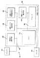
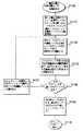
図1は、文書エレメント分割システム100のブロック図の第1の好ましい実施の形態を示す。記述されている文書エレメント分割システム100は、以下に説明される文書エレメント分割方法を実行するための多くの可能な実施の形態の内の一つにすぎない。従って、開示されている文書エレメント分割システム100は、例として示されているだけであり、文書エレメント分割方法を実行するために使用され得るシステムの種々のタイプ及び構成を制限するものではない。
【0009】
図1は、文書画像を分割するための種々の手段を有する汎用コンピュータ400を示している。特に、文書エレメント分割システム100は、メモリ410、連結成分識別手段420、境界ボックス発生手段430、主要ホワイト領域抽出手段440、文書エレメント抽出手段450、及びプロセッサ460を含み、これらの全てはバス手段405によって接続されている。スキャナー200及びプリンタ300も当該バス手段405へ接続されている。文書画像データはスキャナー200によって又はメモリ410から連結成分識別手段420へ最初に入力される。メモリ410は、汎用コンピュータ内に配置されてもよいし、従来の技術において周知のように、ディスクドライブ、CD−ROM、EPROM等の形態で汎用コンピュータの外部に配置されてもよい。同様に、スキャナ200からの文書画像データは、連結成分識別手段420へ入力される前に、最初に、メモリ410へ格納されてもよい。文書画像データは、バイナリ(2値)画像又は複数ビットのディジタル信号の形態で、連結成分識別手段420へ入力され、各ビットは、文書画像の特定画素がオンであるか又はオフであるかを示す。
【0010】
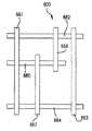
連結成分識別手段420が文書画像データを受け取った後、この連結成分識別手段420は、文書画像内の全ての連結成分を識別する。図3は、代表的な文書画像600を示す。連結成分610は文書画像600内で見つけられる。各連結成分610は、「オフ」(ホワイト)画素によって取り囲まれた、一連の隣接している「オン」(ブラック)画素を備える。文書画像600内の連結成分610を識別するためのシステムは、従来の技術において周知である。
【0011】
文書画像600の連結成分610が識別されると、境界ボックス発生手段430が各連結成分610毎に境界ボックス620を発生する。図3に示されているように、境界ボックス620は、従来の技術において周知であるように、対応する連結成分610を完全に取り囲む最小サイズの矩形ボックスである。連結成分610から境界ボックス620を発生するためのシステムも従来の技術において周知である。
【0012】
境界ボックス情報を有する文書画像データは主要ホワイト領域抽出手段440へ送られ、この主要ホワイト領域抽出手段440は、図4及び図5に示されているように、文書画像600の垂直及び水平方向の主要ホワイト領域660を抽出する。
【0013】
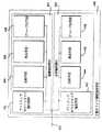
文書ホワイト領域抽出システム110の好ましい実施の形態においては、図2に示されているように、主要ホワイト領域抽出手段440は、二つの部分、即ち、垂直抽出部分441と水平抽出部分442に分かれている。垂直抽出部分441と水平抽出部分442は、それぞれ、プリミティブ(基本的エレメント)ホワイトエリア抽出手段443、比較手段444、除去手段445、及びグループ化手段446を備え、これらの各々がバス手段405に接続されている。垂直抽出部分441と水平抽出部分442は、同一成分を含んでおり、同様の方法で動作する。図4に示されているように、水平抽出部分442は、最初に、プリミティブホワイトエリア630−1乃至630−10を抽出し、水平方向に主要ホワイト領域660を集める。同様に、図5に示されているように、垂直抽出部分441は、最初に、プリミティブホワイトエリア630−11乃至630−19を抽出し、垂直方向に主要ホワイト領域660を集める。
【0014】
水平主要ホワイト領域660のアセンブリは、水平プリミティブホワイトエリア630−1乃至630−10の隣接しているエリアを、特定のルールに従って、単一の水平のグループ化されたプリミティブホワイトエリア630’へグループ化し、併合することによって行われる。同様に、垂直主要ホワイト領域660のアセンブリは、垂直プリミティブホワイトエリア630−11乃至630−19の隣接しているエリアを、特定のルールに従って、単一の垂直のグループ化されたプリミティブホワイトエリア630’へグループ化し、併合することによって行われる。垂直及び水平のプリミティブホワイトエリアのグループ化及び併合が完了した後、幅閾値(しきい値)640より大きな幅と高さ閾値650’より大きな高さとを有する水平プリミティブホワイトエリア630と630’及び高さ閾値650より大きな高さと幅閾値640’より大きな幅とを有する垂直プリミティブホワイトエリア630と630’が主要ホワイト領域660として識別される。図4及び図5に示されている高さ及び幅の閾値640、650、640’及び650’が拡大縮小するように図示されていないことは理解されるべきである。
【0015】
文書画像600において垂直及び水平の主要ホワイト領域660が一旦抽出されると、図6及び図7に示されているように、文書エレメント抽出手段450は、文書画像600内の文書エレメント670を分割するために主要ホワイト領域660を使用する。文書エレメント670は、主要ホワイト領域660をトラックして閉ループを見つけることによって抽出される。その内部に他の閉ループを持たない閉ループは、図7に示されているように、文書エレメント670を文書画像600の残りの部分から分割する。
【0016】
図7に示されているように、他の閉ループを含まない閉ループが三つある。これは文書画像600内に三つの分割された文書エレメント670が含まれていることを意味する。文書エレメント670は矩形形状である必要はなく、または四つ以上の辺を有していてもよい。
【0017】
分割された文書エレメント670はメモリ410、プリンタ300、及びプロセッサ460を含む種々のシステムコンポーネントへ出力される。分割された文書エレメント670がいかにして出力されるかは、当該分割された文書エレメント670を用いて何をなすべきかによる。文書エレメント670はメモリ410に格納されてもよいし又はプリンタ300でプリントされてもよい。分割された文書エレメント670は、例えば、各分割された文書エレメント670内に含まれる連結成分に対して光学的文字認識処理を実行するように、プロセッサ460によって更に処理されてもよい。
【0018】
文書エレメント抽出手段450は、分割された文書エレメント670又は当該分割された文書エレメント670に関する情報を、プリンタ300、メモリ410、又は更なる処理のためにプロセッサ460へ出力する。
【0019】
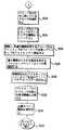
図8は、主要ホワイト領域660を抽出するための方法の好ましい実施の形態を大まかに示している。まず、ステップS100でスタートし、このステップS100において、文書画像600が入力される。入力された文書画像600は、多数の文書エレメント670を有している。ステップS120において、文書画像600の連結成分610が識別される。次に、ステップS130において、境界ボックス620が、ステップS120において識別された各連結成分610毎に発生される。ステップS140において、主要ホワイト領域(背景)660が抽出される。ステップS150において、主要ホワイト領域660によって分割された文書エレメント670が抽出される。ステップS160においてプロセスが終了する。
【0020】
図9は、ステップS140の主要ホワイト領域抽出プロセスの第1の好ましい実施の形態を大まかに示している。ステップS200においては、プリミティブホワイトエリア630が抽出される。図5に示されているように、プリミティブホワイトエリア630は、境界ボックス620同士の間のホワイトスペースの矩形エリアである。次に、ステップS300において、各水平プリミティブホワイトエリア630の高さ及び幅が、幅閾値640と比較され、各垂直プリミティブホワイトエリア660の高さが、高さ閾値650’と比較される。水平方向の幅閾値640は、好ましくは、水平方向の文書画像600の長さの3分の1にセットされる。水平方向の高さ閾値650は、文書画像におけるテキストの行間隔より大きな値にセットされる。垂直方向における高さ閾値650’は、好ましくは、垂直方向にある文書画像600の長さの3分の1にセットされる。垂直方向における幅閾値640’は、文書画像内のテキスト内の行間隔より大きな値にセットされる。
【0021】
ステップS400において、幅閾値640より小さな幅を有する水平プリミティブホワイトエリア630と、高さ閾値650’より小さな高さを有する垂直ホワイトエリア630と、が除去される。ステップS500において、残っているプリミティブホワイトエリア630がグループ化され、主要ホワイト領域660が設定される。最後に、ステップS600において、対応している垂直又は水平の閾値より小さい垂直又は水平の凸部の内の少なくとも一つを有している主要ホワイト領域660が除去される。或いは、対応している閾値より小さな水平及び垂直の両凸部を有している主要ホワイト領域660のみが除去される。次いで、ステップS700において、コントロールはステップS150へ戻る。
【0022】
図10乃至図11は、ステップS200の水平プリミティブホワイトエリア抽出プロセスの第1の好ましい実施の形態を大まかに示している。垂直プリミティブホワイトエリア抽出プロセスは、左右エッジが上下エッジの代わりに使用されていることを除いて、水平ホワイトエリア抽出プロセスと同じである。ステップS210において、ギャップリストが設定される。ステップS212において、ギャップリストは、最初に、第1のプリミティブホワイトギャップ680を含むようにセットされる。プリミティブホワイトギャップ680は、潜在的プリミティブホワイトエリア630であり、この潜在的プリミティブホワイトエリア630は、トップサイド(上部側)とレフトサイド(左側)及びライトサイド(右側)を設定させているが、ボトムサイド(下部側)はまだ設定させていない。ギャップリストに最初に表記された第1のプリミティブホワイトギャップ680は、文書画像600の上部にトップを有し、文書画像600の左側遠方にレフトサイドを有し、文書画像600の右側遠方にライトサイドを有している。ステップS214において、プリミティブホワイトエリアリストは、最初は、空として設定される。
【0023】
ステップS216において、現行走査線1000が、文書画像600の上部に配置されている。ステップS217において、現行走査線1000に沿って左から右へ走査が開始される。ステップS218において、走査線1000は、境界ボックスのエッジ又は文書画像600のエッジが出会ったか否かを決定するためにチェックされる。エッジに出会った場合、コントロールはステップS220へ進む。エッジに出会わなかった場合、コントロールは、現行走査線1000の更なる走査のためにステップS217へ戻る。
【0024】
ステップS220において、出会ったエッジが、境界ボックス620の内の一つのボックスの以前に出会ってないトップである場合、コントロールはステップS222へ飛び越す。このステップ222において、図12に示されているように、境界ボックス620のトップエッジに接触するギャップリスト内のプリミティブホワイトギャップ680Aが識別される。一つ又はそれより多くのこのようなプリミティブホワイトギャップ680Aがあってよい。ステップS223において、境界ボックス620のトップエッジに接触するプリミティブホワイトギャップ680A毎にボトムが設定される。ステップS224において、プリミティブホワイトギャップ680Aがギャップリストから除去される。ステップS226においては、ギャップリストから除去されたプリミティブホワイトギャップ680Aが、プリミティブホワイトエリア630としてプリミティブホワイトギャップリストに表記される。
【0025】
次いで、図13に示されているように、ステップS228において、境界ボックス620のトップエッジと同じラインに沿って配置されたトップと、境界ボックス620のサイドに隣接しているサイドと、を有する新しいプリミティブホワイトギャップ680Bが、設定される。図14及び図15に示されているように、前に出会っていない境界ボックスのトップエッジは、プリミティブホワイトギャップ680Aの垂直エッジの片方又は両方と交差してもよい。この場合、ギャップリストへの新しいプリミティブホワイトギャップ680Bの追加は全く無いか又はあるとしても一つだけにすぎない。ステップS229において、新しいプリミティブホワイトギャップ680Bがギャップリストに表記される。次いで、コントロールは現行走査線1000に沿って更なる走査を行うためにステップS217へ戻る。
【0026】
現行走査線1000の走査はステップS217において続行される。境界ボックス620の内の一つのボックスの他の以前に出会っていないトップエッジに出会った場合、上記のステップS222乃至S229が繰り返される。
【0027】
ステップS220において、出会ったエッジが、境界ボックス620の内の一つの他の以前に出会っていないトップエッジでなかった場合、コントロールはステップS230へ進む。ステップS230においては、出会ったエッジが、境界ボックス620の内の一つのボックスの他の以前に出会っていないボトムエッジである場合、コントロールはステップS232へ進む。ステップS232においては、ボトムエッジが検出されている境界ボックス620のサイドに接触しているプリミティブホワイトギャップ680Bが識別される。一般に、もっと少なくなる可能性はあるが、二つ以下のこのようなギャップ680Bが存在する。稀ではあるが、境界ボックス620の片側が、文書画像660又は他の境界ボックス620のエッジと同じ高さである場合、ギャップ680Bだけが存在する。ステップS233において、境界ボックス620のサイドに接触しているプリミティブホワイトギャップ680B毎にボトムが設定される。ステップ234において、新しく設定されたボトムエッジを有するプリミティブホワイトギャップ680Bがギャップリストから除去される。ステップS236において、プリミティブホワイトギャップ680Bがプリミティブホワイトエリア630としてプリミティブホワイトエリアリスト上で検出される。ステップS238において、新しく出会った境界ボックス620のボトムエッジと同じラインに沿ったトップと、他の境界ボックス620のサイド又は文書画像600の左側遠方に設定されたレフトサイド及び/又は右側遠方に設定されたライトサイドと、を有する新しいプリミティブホワイトギャップ680Cが設定される。ステップS239において、新しく設定されたプリミティブホワイトギャップ680Cは、ギャップリストに表記される。次いで、コントロールは、現行走査線1000に沿って更なる走査を行うためにステップS217へ戻る。
【0028】
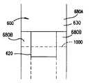
図14乃至図18は、走査線1000内で境界ボックス620のトップ又はボトムに出会った時に発生し得るいくつかの可能性を示す。図14は、境界ボックス620のトップに接触しており、境界ボックス620のライトサイドの右へのみ拡張しているプリミティブホワイトギャップ680Aを示す。プリミティブホワイトギャップ680Aに対するボトムは、境界ボックス620のトップに設定され、新しいプリミティブホワイトギャップ680Bは、境界ボックス620のトップと同じラインに沿ったトップを有する境界ボックス620の右へ設定される。図15は、境界ボックス620のトップエッジに接触しているが、この境界ボックス620のレフトサイド又はライトサイドのどちらにも拡張していないプリミティブホワイトギャップ680Aを示す。このプリミティブホワイトギャップ680Aに対するボトムは、境界ボックス620のトップに設定されるが、新しいプリミティブホワイトギャップ680Bは全く設定されない。
【0029】
図16は、走査線1000内で出会った境界ボックス620のボトムを示している。プリミティブホワイトギャップ680Bは、境界ボックス620のいずれかのサイドに配置され、境界ボックス620のサイドに接触する。従って、境界ボックス620のサイドのいずれかにあるプリミティブホワイトギャップ680Bのためにボトムが設定され、新しく設定されたボトムを有するプリミティブホワイトギャップ680Bがギャップリストから除去され、プリミティブホワイトエリアとしてプリミティブホワイトエリアリストに表記される。境界ボックス620のボトムと同じラインに沿って配置されたトップを有する新しいプリミティブホワイトギャップ680Cは、境界ボックス620のボトムの下に設定される。この新しいプリミティブホワイトギャップ680Cがギャップリストに表記される。
【0030】
図17は、走査線1000内で境界ボックス620のボトムに出会っており、プリミティブホワイトギャップ680Bが境界ボックス620の右側に配置されているのを示している。境界ボックス620の右側に配置されたプリミティブホワイトギャップ680Bに対するボトムが、境界ボックス620のボトムと同じラインに沿って設定され、新しいプリミティブホワイトエリアを設定する。境界ボックス620のボトムと同じラインに沿って配置されたトップと第2の境界ボックス620のライトサイドに沿って配置されたレフトサイドと文書画像600の右端遠方に沿って配置されたライトサイドとを有する新しいプリミティブホワイトギャップ680Cが設定される。
【0031】
図18は、走査線1000内で境界ボックス620のボトムに出会っており、プリミティブホワイトギャップ680Bがこの境界ボックス620のサイドに全く接触していないことを示している。境界ボックス620のボトムにおいてトップを有し、第2の境界ボックス620のライトサイドに沿って配置されたレフトサイドを有し、第3の境界ボックス620のレフトサイド沿って配置されたライトサイドを有している新しいプリミティブホワイトギャップ680Cが設定される。
【0032】
走査線1000における走査は、文書画像の右エッジへ達するまで続けられる。ステップS218において検出されたエッジがトップエッジ又はボトムエッジでない場合、コントロールはステップS220及びステップS230を飛び越してステップS240へ進む。このステップにおいて、文書画像の下の次の走査線が現行走査線1000になる。コントロールはステップS242へ進み、このステップにおいて、現行走査線1000が文書画像の最終の走査線に一致しているか否かを見るためにチェックされる。一致している場合、コントロールはステップS244へ進み、このステップにおいて、ギャップリストに残っている全てのプリミティブホワイトギャップ680A、680B、及び680Cに対するボトムが文書画像600のボトムにおいて設定される。ステップS246において、新しいプリミティブホワイトエリア630が、文書画像600のボトムにおいてボトムを有するプリミティブホワイトギャップ680に対応するプリミティブホワイトエリアリストに表記される。次いで、ステップS248において、コントロールはステップS300へ戻る。
【0033】
図19乃至図20は、ステップS500のプリミティブホワイトエリアを主要ホワイトエリアへグループ化するためのプロセスに対する一つの好ましい実施の形態を大まかに示している。
【0034】
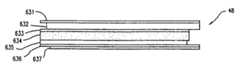
まず、ステップS510においては、ステップS400において、小さすぎるプリミティブホワイトエリアを除去した後に残ったプリミティブホワイトエリア630の各々が調べられる。図21は、小さすぎるプリミティブホワイトエリアの全てが除去された後に残っている多数のプリミティブホワイトエリア630A乃至630Nを示す。ステップS512においては、プリミティブホワイトエリア630A乃至630Nの内の一つ又はそれより多くの各グループへグループラベルがラベル付けされる。プリミティブホワイトエリア630A乃至630Nは、互いに唯一に接触するプリミティブホワイトエリアが同じグループ内にあるようにグループ化される。図22に示されているように、プリミティブホワイトエリア630A乃至630Nは7個の異なるグループ40乃至46へグループ化される。
【0035】
ステップS514において、グループラベルがプリミティブホワイトエリア630A乃至630Nに割り当てられた後で、図22に示されているように、同じグループラベルを有するプリミティブホワイトエリア630のグループが、単一グループ41乃至46へ集められる。次に、ステップS516において、水平グループに対して、各水平グループ40乃至46の各々の高さ650が高さ閾値650と比較される。グループの高さ47は、図23に示されているように、各プリミティブホワイトエリア630の幅の方向に垂直な方向におけるグループのサイズである。従って、垂直グループに対しては、グループの「高さ」47は、水平方向におけるグループのサイズであり、垂直グループの高さ47は、幅閾値640’と比較される。本発明の好ましい実施の形態において、高さ閾値650又は640’は、文書画像600内のテキストの行間隔より大きな値にセットされる。
【0036】
ステップS518において、高さ閾値650又は640’より小さな高さ47を有しており、他のグループに接触しないグループは、除去される。図22のグループ40がこの例である。ステップS520において、高さ閾値650又は640’より小さな高さ47を有しており、一つの面上だけ(グループのボトム上又はグループのトップ上だけ)で他のグループと接触している分岐されたグループは、除去される。図23のグループ45がこの例である。ステップS522において、高さ閾値650又は640’より小さく分割され、分岐されたグループを除去した後で、残っているグループの数は、グループ41乃至44、及び46のうちの二つ又はそれより多くを結合することによって減少されることができる。
【0037】
ステップS524においては、高さ閾値より小さな高さを有するプリミティブホワイトエリアの終端がトリミングされる。これは、図31乃至図33に示されており、以下に詳細に記述されている。
【0038】
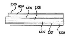
ステップS526においては、(他のグループに)接触しており、共通の左エッジと右エッジを有するグループが単一のプリミティブホワイトエリア630へ併合される。図25及び図26に示されているように、プリミティブホワイトエリア630O及び630P、並びに630Q、630R、630S、及び630Tはそれぞれ共通の左右エッジを有している。三つのグループ内の7個のプリミティブホワイトエリアは、図26に示されているように、三つのプリミティブホワイトエリア630O、630Q、及び630Uへ併合される。
【0039】
ステップS528において、高さ47が高さ閾値650より小さい、除去されたプリミティブホワイトエリア630が再検討されて、これらの再検討されたプリミティブホワイトエリア630の内のいくつかが、ステップS530において、残っているプリミティブホワイトエリア630の内の一つへ戻り、併合されることができるかを決定する。
【0040】
ステップS532において、各残っているプリミティブホワイトエリア630の高さ47が、高さ閾値650又は640’と比較される。ステップS534において、高さ閾値650又は640’より大きな高さ47を有するプリミティブホワイトエリア630が、主要ホワイト領域660であると決定される。
【0041】
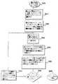
図27は、ステップS512のプリミティブホワイトエリアへラベルを割り当てるプロセスの一つの好ましい実施の形態を大まかに示している。ステップS5121において、文書画像の上部に配置された図21のプリミティブホワイトエリア630Aが現行ホワイトエリアとして選択される。現行検討されているプリミティブホワイトエリアは現行プリミティブホワイトエリアと呼ばれる。ステップS5122において、現行プリミティブホワイトエリアは、ラベルがこの現行プリミティブホワイトエリアへ既に割り当てられたか否かを決定するためにチェックされる。既に割り当てられていた場合、コンロトールは飛び越してステップS5127へ進む。割り当てられていなかった場合、コントロールはステップS5123へ進む。
【0042】
ステップS5123において、現行プリミティブホワイトエリアのトップに接触している他のプリミティブホワイトエリアの数が決定される。当然、最上部のプリミティブホワイトエリア630Aに対してその数はゼロである。これ以外のプリミティブホワイトエリア630に対しては、現行プリミティブホワイトエリアのトップに接触している他のプリミティブホワイトエリア630の数は、ゼロ、1又はそれ以上であってもよい。次に、ステップS5124においては、ステップS5123において決定された現行プリミティブホワイトエリアのトップに接触している他のプリミティブホワイトエリア630の数が正確に1に等しいか否かがチェックされる。1に等しい場合、コントロールはステップS5125へ進み、このステップにおいて、現行プリミティブホワイトエリアのトップに接触している単一の他のプリミティブホワイトエリア630に割り当てられたラベルは現行プリミティブホワイトエリアへも割り当てられる。1に等しくないとき、現行プリミティブホワイトエリアのトップに接触しているゼロ又は一つより多くの他のプリミティブホワイトエリアが存在していれば、コントロールはステップS5126へ飛び越し、このステップにおいて、新しいラベルが現行プリミティブホワイトエリアへ割り当てられる。これは、最上部のプリミティブホワイトエリア630Aに対しても当然の状況である。次いで、ステップS5125及びステップS5126は、共に、ステップS5127へ進む。
【0043】
ステップS5127において、現行プリミティブホワイトエリアのボトムに接触している他のプリミティブホワイトエリア630の数が決定される。次いで、ステップS5128において、現行プリミティブホワイトエリアのボトムに接触している数が、1以下か否かを決定するためにチェックされる。1以下の場合、コントロールはステップS5130へ飛び越す。1以下でない場合、コントロールはステップS5129へ進み、このステップにおいて、現行プリミティブホワイトエリアのボトムに接触している他のプリミティブホワイトエリア630の各々には新しくて異なるラベルが割り当てられる。
【0044】
コントロールはステップS5130へ進み、このステップにおいて、文書画像は、ラベルが文書600のプリミティブホワイトエリア630のどれかに割り当てられるべきかを決定するためにチェックされる。ラベルを割り当てるように決定された場合、コントロールはステップS5131へ戻り、このステップにおいて、最上部の割当てられていないプリミティブホワイトエリア630が現行プリミティブホワイトエリアとして選択される。次いで、コントロールは、ステップS5130からステップS5122へ戻る。ラベルが割り当てられない場合、割当てられていないプリミティブホワイトエリア630が残っていなければ、コントロールはステップS5132へ進み、このステップにおいて、コントロールはS514へ戻る。
【0045】
図28は、ステップS522のプリミティブホワイトエリアグループをグループ化する方法のための一つの好ましい実施の形態を大まかに示している。ステップS5221において、最上部及び最左部の検討されていないホワイトエリアグループが現行プリミティブホワイトエリアグループとして選択される。ステップS5222において、現行プリミティブホワイトエリアグループのボトムに接触している他のプリミティブホワイトエリアグループの数が決定される。ステップS5223において、現行プリミティブホワイトエリアグループのボトムに接触している他のプリミティブホワイトエリアグループの数が1に等しくない場合、コントロールはステップS5227へ飛び越す。或いは、その数が1に等しい場合、コントロールはステップS5224へ進む。このステップにおいて、現行グループのボトムに接触している単一グループのトップに接触しているグループの合計が決定される。次いで、ステップS5225において、接触しているグループの合計がぴったり1に等しい場合、コントロールはステップS5226へ進む。1に等しくない場合、コントロールは再びステップS5227へ進む。ステップS5226において、現行プリミティブホワイトエリアグループのボトムに接触している単一プリミティブホワイトエリアグループに割り当てられたラベルは、現行プリミティブホワイトエリアに割り当てられたラベルと置き換えられ、これによって、二つのグループが併合される。次いで、コントロールはステップS5222へ戻る。
【0046】
ステップS5227において、文書画像600は、検討されていないプリミティブホワイトエリアグループが当該文書画像600内に残っているか否かを決定するためにチェックされる。検討されていないプリミティブホワイトエリアグループが当該文書画像600内に残っている場合、コントロールは、次のグループが現行グループとして選択されるステップS5228へ進む。次いで、コントロールはステップS5222へ飛び越して戻る。検討されていないプリミティブホワイトエリアグループが当該文書画像600内に残っていない場合、コントロールはステップS5229へ飛び越し、このステップはコントロールをステップS524へ戻す。
【0047】
図29及び図30は、ステップS5241のグループ内のプリミティブホワイトエリアの終端をトリミングするための手順の一つの好ましい実施の形態を大まかに示している。まず、ステップS524において、プリミティブホワイトエリアグループの第1のグループが、現行プリミティブホワイトエリアグループとして選択される。次に、ステップS5242において、現行プリミティブホワイトエリアグループの最左側(レフトサイド)が現行最左側として識別され、当該最左側を有する現行プリミティブホワイトエリアグループのプリミティブホワイトエリアが現行エリア又は現行サブグループとして識別される。次いで、ステップS5243において、プリミティブホワイトエリアの現行グループの現行プリミティブホワイトエリア又は現行サブグループの現行最左側の高さ47が、高さ閾値650又は640’と比較される。高さ閾値650又は640’が越えられない場合、コントロールはステップS5244へ進み、このステップにおいて、現行グループが、現行エリア又はサブグループに接触しているプリミティブホワイトエリアが残っているか否かを見るためにチェックされる。
【0048】
接触しているプリミティブホワイトエリアが残っている場合、コントロールはステップS5245へ進む。接触しているプリミティブホワイトエリアが残っていない場合、コントロールはステップS5246へ飛び越す。ステップS5245において、現行エリア又はサブグループに接触している現行プリミティブホワイトエリアの次の最左側が現行最左側として識別される。このプリミティブホワイトエリアは現行サブグループ又は現行エリアへ追加されて、現行サブグループを形成する。次いで、コントロールはステップS5243へ戻る。このループは、現行エリア又はサブグループの現行最左側の高さが高さ閾値650又は640’を越えなくなる迄、又は接触しているプリミティブホワイトエリアが無くなる迄、適所に残る。次いで、コントロールはステップS5246へ進む。
【0049】
ステップS5246において、現行プリミティブホワイトエリア又はサブグループの現行最左側の左へ延びる現行プリミティブホワイトエリアグループ内のプリミティブホワイトエリアの終端が除去される。次いで、コントロールはステップS5247へ進み、このステップは、左端が未だトリミングされていないと共に当該左端の高さが高さ閾値に等しいか又はそれより小さい現行グループの他のプリミティブホワイトエリアがあるか否かを決定する。左端がトリミングを必要とする他のエリアが残っている場合、コントロールはステップS5247からステップS5242へ戻る。
【0050】
左端がトリミングを必要とする他のエリアが無い場合、コントロールはステップS5248へ進み、このステップは、現行プリミティブホワイトエリアグループのプリミティブホワイトエリアの最右側(ライトサイド)を現行最右側として識別する。コントロールは次いでステップS5249へ進み、このステップにおいて、現行最右側の高さ47は、高さ閾値650又は640’と比較される。高さ閾値650又は640’を越えない場合、コントロールはステップS5250へ進み、このステップにおいて、現行グループは、現行エリア又はサブグループに接触しているプリミティブホワイトエリアが残っているか否かを見るためにチェックされる。
【0051】
現行エリア又はサブグループに接触しているプリミティブホワイトエリアが残っている場合、コントロールはステップS5251へ進む。或いは、現行エリア又はサブグループに接触しているプリミティブホワイトエリアが残っていない場合、コントロールはステップS5252へ飛び越す。ステップS5251において、現行プリミティブホワイトエリアグループの現行ホワイトエリア又はサブグループに接触しているプリミティブホワイトエリアの次の最右側が、現行最右側として識別される。コントロールは次いでステップS5249へ戻る。このループは、高さ閾値が越えられなくなる迄、又は接触しているプリミティブホワイトエリアが無くなる迄、続けられる。次いで、コントロールはステップS5252へ進み、このステップにおいて、現行最右側の右へ延びる現行プリミティブホワイトエリア又はサブグループのプリミティブホワイトエリアの終端が除去される。
【0052】
コントロールはステップS5253へ進み、このステップは、右端が未だトリミングされていないと共に当該右端の高さが高さ閾値に等しいか又はそれより小さい現行グループの他のプリミティブホワイトエリアがあるか否かを決定する。右端がトリミングを必要とする他のエリアがある場合、コントロールはステップS5248へ飛び越して戻る。或いは、トリミングを必要とする他のエリアが無い場合、コントロールはステップS5254へ進み、このステップは、トリミングされていないプリミティブホワイトエリアグループが文書画像600内に残っているか否かを決定する。トリミングされていないプリミティブホワイトエリアグループが文書画像600内に残っている場合、コントロールはステップS5255へ進む、このステップにおいて、次のプリミティブホワイトエリアグループが現行プリミティブホワイトエリアグループとして選択される。コントロールは次いでステップS5242へ戻る。或いは、文書画像600のプリミティブホワイトエリアグループの全てがトリミングされている場合、コントロールはステップS5256へ進み、このステップはコントロールをステップS526へ戻す。
【0053】
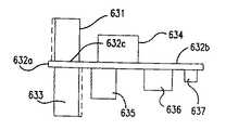
図31乃至図33は、図29及び図30に示されたトリミングプロセスの動作をグラフィカルに示している。図31に示されているように、グループ48は、個々のプリミティブホワイトエリア631乃至637を備える。最初に、プリミティブホワイトエリア635及び636は、グループ48の最左端を画定する。プリミティブホワイトエリア635及び636の共通左端の垂直高さ47は、高さ閾値650と比較される。図31に示されているように、プリミティブホワイトエリア636の最下端から測定される時、高さ閾値650は、プリミティブホワイトエリア634の上端を越えているがプリミティブホワイトエリア633の上端より下にある。従って、プリミティブホワイトエリア635及び636は、現行サブグループとして一緒にグループ化され、この現行サブグループに接触しているプリミティブホワイトエリアが識別される。図31においては、プリミティブホワイトエリア634及び637を含む。
【0054】
従って、図32に示されているように、プリミティブホワイトエリア635及び636の左端は、プリミティブホワイトエリア634の左端へ戻るようにトリミングされる。この新しい左端の高さは、高さ閾値650と比較される。高さ閾値650が越えられていないので、プリミティブホワイトエリア634乃至636の左端は、プリミティブホワイトエリア633の左端に戻るようにトリミングされる。同様に、プリミティブホワイトエリア631の左端もプリミティブホワイトエリア632の左端に戻るようにトリミングされる。現行エリア又はグループの左端は、現行エリア又はグループに接触しているプリミティブホワイトエリアの次の最左端に合わせて調整されるか又はトリミングされる。
【0055】
図31乃至図33において、プリミティブホワイトエリア632は、プリミティブホワイトエリア631に接触しているが、他のプリミティブホワイトエリア633乃至637は、プリミティブホワイトエリア631に接触していない。プリミティブホワイトエリア631の高さ47は、高さ閾値650に比較するには及ばないが、当該プリミティブホワイトエリア631は、グループ48の最左点が高さ閾値650を越えないプリミティブホワイトエリアのプリミティブホワイト領域のトリミングされたサブグループの最左端より更に左へ延びないように、戻るようにトリミングされる。図33に示されているように、プリミティブホワイトエリア633乃至636によって画定されたグループ48の最左端は、高さ閾値650を越えないので、グループ48の最左端に対するトリミングプロセスが終了する。
【0056】
次いで、このプロセスは、グループ48の最右端に対して繰り返される。この場合、プリミティブホワイトエリア636及び637の最右端によって画定されたグループ48の最右端は、まず、プリミティブホワイトエリア631及び632の最右端と同一線になるように戻るようにトリミングされる。これらのプリミティブホワイトエリアは隣接しておらず、どれも単独では高さ閾値650を越えないので、プリミティブホワイトエリア631、632、636、及び637の最右端は、プリミティブホワイトエリア631乃至634の最右端へ戻るように更にトリミングされる。プリミティブホワイトエリア631乃至634によって画定された最右端が高さ閾値47を越えているので、トリミングプロセスは終了する。
【0057】
図34は、二つ又はそれより多くのプリミティブホワイトエリア630を単一のプリミティブホワイトエリア630へ併合するプロセスの一つの好ましい実施の形態を示している。ステップS5301において、第1のプリミティブホワイトエリア630が現行プリミティブホワイトエリアとして選択される。ステップS5301において、現行ホワイトエリアが、その垂直高さが垂直閾値より大きいか又はそれより小さいかを決定するためにチェックされる。現行ホワイトエリアの垂直高さが垂直閾値より大きい場合、コントロールはステップS5302を飛び越してステップS5311へ進む。或いは、現行ホワイトエリアの垂直高さが垂直閾値より小さい場合、コントロールはステップS5303へ進む。
【0058】
ステップS5303において、現行プリミティブホワイトエリアに接触している他のプリミティブホワイトエリアのリストが発生される。次いで、ステップS5304において、接触エリアのリストは、二つの接触エリアが現行ホワイトエリアの同じ部分に接触しているか否かを決定するためにチェックされる。例えば、図35に示されているように、接触しているプリミティブホワイトエリア631及び633は、現行ホワイトエリ632の同じ部分に接触している。同様に、接触しているプリミティブホワイトエリア634及び635も現行ホワイトエリア632の同じ部分に接触している。現行ホワイトエリアの同じ部分に接触している、リスト上のペアの接触エリアが存在しない場合、コントロールはステップS5308へ飛び越す。或いは、現行ホワイトエリアの同じ部分に接触している二つの接触エリアが存在している場合、コントロールはステップS5305へ進む。
【0059】
ステップS5305において、ペアの接触エリアのエッジが充分に位置合わせされているか否かを決定するためにチェックされる。例えば、図35に示されているように、接触しているホワイトエリア631及び633のエッジは充分に位置合わせされているが、接触エリア634及び635のエッジは充分に位置合わせされていない。ステップS5304の通過毎に二つの接触エリアの一つのペアが選択され、ステップS5305において、この選択されたペアがチェックされる。ステップS5305において、エッジが充分に位置合わせされていない場合、コントロールはステップS5304へ飛び越して戻り、このステップは、接触エリアのペアの内の他の一つをチェックする。ステップS5305を介してステップS5304へ戻るこのループは、各接触ペアがチェックされるまで続けられる。
【0060】
ステップS5305において、ペアの接触エリアのエッジが充分に位置合わせされている場合、コントロールはステップS5306へ進み、このステップにおいて、ペアの接触エリアが接触エリアのリストから除去され、図36に示されているように、現行ホワイトエリアは三つの部分へ分割される。当然、ペアの接触エリアの両左端又は両右端が、それぞれ、現行ホワイトエリアの左端又は右端と位置合わせされている場合、現行ホワイトエリアは二つの部分に分割されるにすぎない。ステップS5307において、これら二つの接触エリアと現行ホワイトエリアの接触された部分が単一ホワイトエリアへ併合される。このプロセスは、図36及び図37に示され、これらの図において、接触エリア632及び633並びに現行ホワイトエリア632cが単一ホワイトエリア631へ併合される。次いで、ステップS5304へ戻り、コントロールは接触エリアのペアの内の他の一つのペアをチェックする。
【0061】
ステップS5304乃至S5307のループにおいて、全ての接触エリアのペアが一旦分析されると、コントロールはステップS5304からステップS5308へ飛び越す。ステップS5308において、接触エリアのリストが、当該リストにエリアが残っているか否かを決定するためにチェックされる。接触しているエリアがリスト上に残っていない場合、コントロールはステップS5308からステップS5311へ進む。そうでなく、接触しているエリアのリストにエリアが残っている場合、コントロールはステップS5309へ進む。
【0062】
接触しているエリアのリストに残っている最も幅の広い接触エリアが選択され、当該選択された最も幅の広いエリアが接触している現行ホワイトエリアの部分が更に三つの部分に分割される。図36及び図37において、最も幅の広い残っている部分634が、現行ホワイトエリア632の部分632bに接触している。従って、部分632bは、更に、非接触部分632d及び接触された部分632cへ分割される。図38に示されているように、接触された部分632cは最も幅の広いエリア634へ併合される。
【0063】
ステップS5310において、選択された最も幅の広いエリアがリストから除去され、当該選択された最も幅の広いエリアと同じ現行プリミティブホワイトエリアの部分に接触しているリスト上の他のエリアも、接触エリアのリストから除去される。コントロールは、ステップS5310からステップS5308へ戻って、接触しているエリアのリストにエリアが残っているか否かを再び決定する。リスト上に残っている全ての接触しているエリアが一旦選択され、これらの選択されたエリアが接触している現行ホワイトエリアの部分がそれらに併合されると、コントロールは、ステップS5308からステップS5311へ飛び越し、このステップS5311は、選択されていないプリミティブホワイトエリアが文書画像内に残っているか否かを決定する。選択されていないプリミティブホワイトエリアが文書画像内に残っている場合、コントロールはステップS5311からステップS5313へ飛び越し、このステップにおいて、次のプリミティブホワイトエリアが現行ホワイトエリアとして選択される。ステップS5313において、次のプリミティブホワイトエリアが現行ホワイトエリアとして選択されると、コントロールは飛ばしてステップS5302へ戻り、このステップにおいて、現行ホワイトエリアが垂直閾値に対して再度チェックされる。そうではなく、文書画像のプリミティブホワイトエリアの全てが選択され、垂直閾値と比較された場合、コントロールはステップS5312へ進み、このステップはコントロールをステップS532へ戻す。
【0064】
図35に示されているように、現行ホワイトエリア632には、6個の他のプリミティブホワイトエリア631、及び633乃至637が接触している。プリミティブホワイトエリア631及び634は、垂直閾値と前もって比較され、これらのエリアが閾値より小さい場合、前もって解析される。この場合、接触しているプリミティブホワイトエリア631又は634のいづれも垂直閾値より小さい。上記のように、接触しているホワイトエリアのリストが一旦発生されると、現行プリミティブホワイトエリア632の共通部分に接触し且つ充分に位置合わせしているエッジを有するこれらの接触しているプリミティブホワイトエリアは、単一ホワイトエリアへ併合される。従って、図36に示されているように、接触しているプリミティブホワイトエリア631及び633は、現行部分632の共通に接触している部分632cに沿って共に併合される。また、接触しているプリミティブホワイトエリア631及び633のエッジは、共通に接触している部分632cのエッジに位置合わせされるように、戻るようにトリミングされる。現行プリミティブホワイトエリアの共通部分にも接触している他の接触しているホワイトエリア634及び635のエッジは、充分に位置合わせされていないので、これらは併合されない。
【0065】
図37に示されているように、接触しているエリアのリストに最も広い残っている接触エリアが選択され、現行ホワイトエリア部分632の接触された部分632cが、選択された最も(幅の)広い残っているホワイトエリア634に併合される。同時に、当該接触されたエリア632cにも接触している接触しているエリアのリスト上のあらゆる他の接触エリアが接触エリアのリストから除去される。最も広い残っている接触エリアを検索するプロセスは、接触しているプリミティブホワイトエリアがプリミティブホワイトエリアのリストから無くなるまで続けられる。従って、図38に示されているように、現行エリア632の接触された部分が接触ホワイトエリア636及び637へ併合され、現行ホワイトエリアは接触されていない部分632d、632f、及び632gへ更に分割される。
【0066】
図39は、ステップS150の文書エレメントを抽出する方法の一つの好ましい実施の形態を大まかに示している。図39に示されているように、文書画像670を抽出するために、閉ループを形成しない主要ホワイト領域660は除去される。ステップS800において、残っている主要ホワイト領域660がセグメントへ分割される。ステップS900において、最も外側のセグメント、即ち、文書画像600の境界に最も近接しているセグメントが第1の方向においてトラッキングされ、各トラッキングされたセグメントの第1の方向のフィールドがマーキングされる。ステップS1000において、セグメントのリストから第1の最上部の水平セグメントが第1の及び現行セグメントとして選択される。
【0067】
次に、ステップS1100において、第1のセグメントを含む現行閉ループは、前記第1の方向と反対の方向に移動することによって発生され、この方向に対応している各セグメントの方向フィールドがマーキングされる。ステップS1200において、マーキングされた両方向のフィールドを有するセグメントは除去される。ステップS1300において、現行閉ループによって定義された現行文書エレメント670が出力される。ステップS1400においては、セグメントのリストがセグメントが当該リストに残っているか否かを決定するためにチェックされる。セグメントが当該リストに残っている場合、コントロールはステップS1500へ進み、このステップにおいて、当該リストに残っている最上部の水平セグメントが当該セグメントのリストから選択される。コントロールはステップS1100へ進む。当該セグメントのリストにセグメントが残っていない場合、コントロールはステップS1400からステップS1600へ進み、このステップはコントロールをステップS160へ戻す。
【0068】
図40は、ステップS700の閉ループを形成しない主要ホワイト領域を除去するプロセスの一つの好ましい実施の形態を大まかに示している。最初に、ステップS710においては、少なくとも二つの他の主要ホワイト領域660と接触していない主要ホワイト領域660が検出される。これは、図44にグラフィカルに示されており、この図において、主要ホワイト領域660乃至667の内の主要ホワイト領域666と667が、それぞれ、一つだけの他の主要ホワイト領域と接触している。従って、これらの領域はステップS720において除去される。次いで、ステップS730において、文書画像600は、少なくとも二つの他の領域に接触できない領域が残っているか否かを決定するために再度チェックされる。図44に示されているように、主要ホワイト領域665が、二つの他の主要ホワイト領域661と667とに最初に接触した。しかしながら、主要ホワイト領域667が前もって除去されているので、主要ホワイト領域665は、この場合、一つだけの他の主要ホワイト領域と接触している。
【0069】
少なくとも二つの他の主要ホワイト領域に接触できない主要ホワイト領域が残っている場合、コントロールはステップS730からステップS710へ戻る。少なくとも二つの他の主要ホワイト領域に接触できない主要ホワイト領域が残っていない場合、コントロールはステップS730からステップS740へ進み、このステップにおいて、コントロールがステップS800へ戻される。これにより、図44における文書画像600は、図45に示されているように、主要ホワイト領域661乃至664を残して除去された主要ホワイト領域665乃至666を有する。
【0070】
図41は、ステップS800の残っている主要ホワイト領域660をセグメントへ分割するためのプロセスの一つの好ましい実施の形態を示している。最初に、ステップS810においては、主要ホワイト領域660の内の一つが現行ホワイト領域として選択される。次に、ステップS820においては、現行主要ホワイト領域660上の交差点、即ち、当該現行主要ホワイト領域660が他の主要ホワイト領域660と接触する場所が検出される。ステップS830において、現行主要ホワイト領域が各交差点で分割されて、セグメントを形成する。このプロセスは、図46及び図47にグラフィカルに示されている。文書画像600は主要ホワイト領域661乃至667を備える。図47に示されているように、主要ホワイト領域661は、それが、主要ホワイト領域662、664、及び665と交差する三つの交差点を有する。従って、主要ホワイト領域661は、四つのセグメント661a乃至661dへ分割される。同様に、主要ホワイト領域662は、それが、主要ホワイト領域661、666、及び663と交差される三つの交差点を有する。従って、主要ホワイト領域662は、セグメント662a乃至662dへ分割される。同様に、主要ホワイト領域663乃至667が、セグメント663a乃至663c、664a乃至664d、665a乃至665c、666a乃至666c、及び667a乃至667cへ分割される。
【0071】
次いで、ステップS840において、図48に示されているように、単一交差点のみによって境界付けされた、文書画像600のセグメントは、除去される。図48に示されているように、セグメント661a、661d、662a、662d、663a、663c、664a、664d、665a、665d、666a、666c、667a、乃び667cは、交差点によって境界付けされない一端を有しているので、文書画像600から除去される。従って、これは、文書画像660上に残っているセグメント661b乃至c、662b乃至c、663b、664b乃至c、665b乃至c、666b及び667bを残す。
【0072】
次に、ステップS850において、現行主要ホワイト領域がセグメントされ、その境界付けされていないセグメントが除去された後で、文書画像600は、まだ分割されていない主要ホワイト領域が残っているか否かを決定するためにチェックされる。まだ分割されていない主要ホワイト領域が残っている場合、コントロールはステップS860へ進み、このステップにおいて、次の分割されていない主要ホワイト領域が現行領域として選択される。コントロールは飛び越してステップS820へ戻る。文書画像600内の主要な未分割のホワイト領域が残っていない場合、コントロールはステップS850からステップS870へ飛び越し、このステップはコントロールをステップS900へ戻す。
【0073】
図38は、ステップS900の最も外側のセグメントのリストを発生するための方法の一つの好ましい実施の形態を示す。各セグメントは、このセグメントが各方向(水平セグメントの場合、左から右、右から左、垂直セグメントの場合、上から下、下から上)においてトラックされていることを示すために、当該セグメントに対応している二つのフィールドを有している。最初に、ステップS910において、最上部及び最下部の水平セグメントが、第1のセグメント及び現行セグメントとして選択される。水平サポートを選択することは必要とされず、その代わりに垂直セグメントが選択されることが理解されよう。選択されたセグメントにおいて、左から右への方向を示すフィールドがマーキングされる。図49に示された文書画像600の場合、これはセグメント662bである。
【0074】
次に、ステップS920において、第1のセグメントの右交差点が最終の交差点として選択される。図49において、これは、セグメント662bと662cを結ぶ交差点である。
【0075】
ステップS940において、現行セグメントは、現行セグメントの次の交差点に出会うまで、最終交差点から現行セグメントに沿って反時計回りに移動することによってトラックされる。ステップS950において、次のセグメントは、トラッキング(追跡)の反対方向から出発しながら、セグメントが見つかるまで、次の交差点の回りを反時計回りに探索することによって選択される。図49において、これはセグメント661bであり、セグメント662bの左手交差点回りの動作がラインAで示されている。トラックされた方向、右から左の方向に対応しているフィールドがマーキングされる。
【0076】
ステップS960において、次のセグメントがそれが第1のセグメントであるか否かを見るためにチェックされる。第1のセグメントでなければ、コントロールはステップS970へ進み、このステップにおいて、次の交差点が最終の交差点として選択され、次のセグメントが現行セグメントとして選択される。コントロールは次いでステップS930へ進む。このプロセスは、セグメント661c、664b、664c、663b、及び662cをトラックする。各セグメント内のこれらのトラックされた方向に対応しているフィールドがマーキングされる。
【0077】
しかしながら、ステップS960において、次のセグメントが第1のセグメントである場合、コントロールはステップS980へ飛び越し、このステップはコントロールをステップS1000(図39)へ戻す。これらのセグメントの内のどれかがステップS910の開始点として選択され得ることが理解されよう。
【0078】
図43はステップS1100の現行の最も内側の閉ループを発生するための方法の一つの好ましい実施の形態を示している。ステップS1110において、セグメントのリストの最上部の水平セグメントは、第1のループセグメントとして及び現行ループセグメントとして選択され、現行の最も外側のセグメントの左交差点は最終セグメントとして選択される。ステップS1120において、現行ループセグメントは、現行ループセグメントの次の交差点が見つかるまで、最終交差点から時計回りにトラックすることによって走査される。ステップS1130において、トラッキングの反対方向から開始しながら、セグメントが見つかるまで、次の交差点の回りを反時計回りに探索することによって次のセグメントが選択される。図50に示されているように、ステップS1130において形成されたラインは、セグメント662bの右手交差点の回りのラインBに沿って反時計回りに回転される。
【0079】
次いで、ステップS1140においては、次のループセグメントが、それが第1のループセグメントであるか否かを見るためにチェックされる。次のループセグメントが第1のループセグメントでなければ、コントロールはステップS1150へ進み、このステップにおいて、次のループセグメントが現行ループセグメントとして選択され、次の交差点が最終交差点として選択される。このプロセッスは、図51に示されており、この図において、セグメント662b、666b、665c、665b、及び661cが、第1の文書エレメント671を取り囲むインターループを形成する。各セグメント内のトラックされた方向に対応しているフィールドがマーキングされる。
【0080】
ステップS1140において、次のセグメントが第1のセグメントである場合、コントロールはステップS1140へ飛び越し、このステップにおいて、現行閉ループは終了したものとして処理され、この閉ループの内部が次の文書エレメントとして識別される。次いで、コントロールはステップS1170へ進み、このステップはコントロールをステップS1200(図39)へ戻す。
【0081】
図52及び図53は、第2及び第3の文書エレメント672及び673を識別するためのプロセスを示している。図52に示されているように、第1の文書エレメント671が一旦検出されると、セグメント661b及び662bが除去される。ステップS1200に対して上記に示されているように、最も外側のループを見つけるにあたって、これらの各セグメントの両フィールドが既にマーキングされていたので、これらのセグメント661b及び662bは除去される。閉ループが反時計回り方向に追跡されている場合、次の交差点からのラインが時計回りに回転されることが理解されよう。
【0082】
【発明の効果】
本発明は、文書画像上のホワイト領域のみを解析することによって文書画像内のエレメントを識別するためのシステムを提供する。
【図面の簡単な説明】
【図1】本発明の文書分割システムの好ましい実施の形態を示すブロック図である。
【図2】主要ホワイト領域抽出手段の好ましい実施の形態を示すブロック図である。
【図3】サンプル文書画像を示す図である。
【図4】抽出された水平プリミティブホワイトエリアを有する文書画像を示す図である。
【図5】抽出された垂直プリミティブホワイトエリアを有する文書画像を示す図である。
【図6】抽出された主要ホワイト領域を有する文書画像を示す図である。
【図7】分割され、抽出された文書エレメントを示す図である。
【図8】主要ホワイト領域及び文書エレメントを抽出する方法の一つの実施の形態を示すフローチャートである。
【図9】主要ホワイト領域を抽出する方法の一つの実施の形態を示すフローチャートである。
【図10】プリミティブホワイトエリアを抽出する方法の一つの実施の形態を示すフローチャートである。
【図11】プリミティブホワイトエリアを抽出する方法の一つの実施の形態を示すフローチャートである。
【図12】境界ボックスのトップが走査線内で出会った時にプリミティブホワイトエリアが形成され、プリミティブホワイトギャップが検出される種々の方法をグラフィカルに示す図である。
【図13】境界ボックスのトップが走査線内で出会った時にプリミティブホワイトエリアが形成され、プリミティブホワイトギャップが検出される種々の方法をグラフィカルに示す図である。
【図14】境界ボックスのトップが走査線内で出会った時にプリミティブホワイトエリアが形成され、プリミティブホワイトギャップが検出される種々の方法をグラフィカルに示す図である。
【図15】境界ボックスのトップが走査線内で出会った時にプリミティブホワイトエリアが形成され、プリミティブホワイトギャップが検出される種々の方法をグラフィカルに示す図である。
【図16】境界ボックスのボトムが走査線内で出会った時にプリミティブホワイトエリアが形成され、プリミティブホワイトギャップが検出される種々の方法をグラフィカルに示す図である。
【図17】境界ボックスのボトムが走査線内で出会った時にプリミティブホワイトエリアが形成され、プリミティブホワイトギャップが検出される種々の方法をグラフィカルに示す図である。
【図18】境界ボックスのボトムが走査線内で出会った時にプリミティブホワイトエリアが形成され、プリミティブホワイトギャップが検出される種々の方法をグラフィカルに示す図である。
【図19】残っているプリミティブホワイトエリアを主要ホワイト領域へグループ化する方法の一つの実施の形態を示すフローチャートである。
【図20】残っているプリミティブホワイトエリアを主要ホワイト領域へグループ化する方法の一つの実施の形態を示すフローチャートである。
【図21】プリミティブホワイトエリアがラベル付けされ、除去され、グループ化される種々の方法をグラフィカルに示す図である。
【図22】プリミティブホワイトエリアがラベル付けされ、除去され、グループ化される種々の方法をグラフィカルに示す図である。
【図23】プリミティブホワイトエリアがラベル付けされ、除去され、グループ化される種々の方法をグラフィカルに示す図である。
【図24】プリミティブホワイトエリアがラベル付けされ、除去され、グループ化される種々の方法をグラフィカルに示す図である。
【図25】プリミティブホワイトエリアがラベル付けされ、除去され、グループ化される種々の方法をグラフィカルに示す図である。
【図26】プリミティブホワイトエリアがラベル付けされ、除去され、グループ化される種々の方法をグラフィカルに示す図である。
【図27】グループラベルをプリミティブホワイトエリアへ割り当てる方法の一つの実施の形態を示すフローチャートである。
【図28】再グループ化のために残っているグループを検査する方法の一つの実施の形態を示すフローチャートである。
【図29】グループ内のプリミティブホワイトエリアの終端をトリミングする方法の一つの実施の形態を示すフローチャートである。
【図30】グループ内のプリミティブホワイトエリアの終端をトリミングする方法の一つの実施の形態を示すフローチャートである。
【図31】プリミティブホワイトエリアの終端がどのようにトリミングされ、併合されるかをグラフィカルに示す図である。
【図32】プリミティブホワイトエリアの終端がどのようにトリミングされ、併合されるかをグラフィカルに示す図である。
【図33】プリミティブホワイトエリアの終端がどのようにトリミングされ、併合されるかをグラフィカルに示す図である。
【図34】隣接しているプリミティブホワイトエリアを単一プリミティブホワイトエリアへ併合する方法の一つの実施の形態を示すフローチャートである。
【図35】プリミティブホワイトエリアが他の隣接しているプリミティブホワイトエリアにどのように併合されるかをグラフィカルに示す図である。
【図36】プリミティブホワイトエリアが他の隣接しているプリミティブホワイトエリアにどのように併合されるかをグラフィカルに示す図である。
【図37】プリミティブホワイトエリアが他の隣接しているプリミティブホワイトエリアにどのように併合されるかをグラフィカルに示す図である。
【図38】プリミティブホワイトエリアが他の隣接しているプリミティブホワイトエリアにどのように併合されるかをグラフィカルに示す図である。
【図39】文書画像を抽出するための方法の一つの実施の形態を示すフローチャートである。
【図40】閉ループを形成しない主要ホワイト領域を除去する方法の一つの実施の形態を示すフローチャートである。
【図41】残っている主要ホワイト領域をセグメントへ分割するための方法の一つの実施の形態を示すフローチャートである。
【図42】最も外側のセグメントのリストを発生する方法の一つの実施の形態を示すフローチャートである。
【図43】最も内側のセグメントのリストを発生する方法の一つの実施の形態を示すフローチャートである。
【図44】主要ホワイト領域が除去される前に主要ホワイト領域へ分割された文書画像を示す図である。
【図45】除去された閉ループを形成しない前記主要ホワイト領域を有する図44の文書画像を示す図である。
【図46】残っている主要ホワイト領域がセグメントへ分割される前に他の文書画像を示す図である。
【図47】セグメントへ分割された図46の文書画像を示す図である。
【図48】除去された唯一の交差点によって境界付けされたセグメントを有する図47のセグメントされた文書画像を示す図である。
【図49】発生された最も外側のセグメントのリストを有する図48の文書画像を示す図である。
【図50】内部の閉ループを形成する方法をグラフィカルに示す図である。
【図51】第1の閉ループが終了した後の図48の文書画像を示す図である。
【図52】第2の閉ループが終了した後の図48の文書画像を示す図である。
【図53】第3及び最終の閉ループが終了した後の図48の文書画像を示す図である。
【符号の説明】
100 文書エレメント分割システム
410 メモリ
420 連結成分識別手段
430 境界ボックス発生手段
440 主要ホワイト領域抽出手段
450 文書エレメント抽出手段
460 プロセッサ[0001]
BACKGROUND OF THE INVENTION
The present invention relates to a method and apparatus for extracting main white areas and document elements from a document image.
[0002]
[Prior art]
The method of segmenting the text area is described in "Image Segmentation By Shape-Directed Covers" on pages 820-825, 10th "Pattern Recognition" International Conference, June 16-21, 1990. ”)”) By Baird et al. The method disclosed in Baird analyzes white space in document images, but clearly discloses the termination rules for text region segmentation. Not.
[0003]
Other methods for segmenting document elements in the document image are also disclosed, but none of these methods analyze white areas in the document image and extract and analyze the main white areas The document element is not divided by The white area is an area of a document that does not include any connected components.
[0004]
[Problems to be solved by the invention]
The present invention provides a system for identifying elements in a document image by analyzing only white areas on the document image.
[0005]
The present invention also provides a document element segmentation system that can extract a document image from a document image that is not necessarily formed into a rectangle.
[0006]
[Means for Solving the Problems]
With the present invention, it is not necessary to analyze the portion of the document image that contains the document elements to determine which connected components form a coherent group or document element. The image on the document is scanned to produce an electronic or digital representation of the image. The main white area is a rectangular area of white space having a predetermined minimum size. Document elements are areas that contain information such as text and graphics and are separated from each other by a main white area. An area that contains document elements and is separated from other areas by a predetermined size of white space is assumed to be a separate document element. Examples of such document elements in a document image are the document title (title), author, footnote, text typeface, etc. Once extracted, these document elements are further processed by an optical character recognition unit or the like.
[0007]
The invention according to
According to a second aspect of the present invention, there is provided a document image dividing method for dividing a document image formed by a plurality of pixels each indicated by an image signal portion into at least one document element, wherein the image signal is input. Each of the at least one connected component, the step of storing the image signal, the step of identifying at least one connected component consisting of adjacent on-pixels from the plurality of pixels forming the document image, Generating a bounding box of a minimum size that completely surrounds the connected component on the outer periphery, recognizing a background area surrounding the bounding box as a closed loop region and making the closed loop region into a plurality of closed regions; Dividing and identifying each of the plurality of closed regions, and a portion constituting the background area Among the plurality of closed regions, the ones having horizontal and vertical lengths smaller than the threshold are removed, and the remaining regions are grouped to form a closed loop surrounding the bounding box from the background area. Extracting the main background area, which is a plurality of the closed areas, and extracting the at least one document element based on the extracted main background area, An extracting step reviews the removed area and determines whether any of the reviewed areas can be merged with the main background area, and merges if there is any that can be merged Including the step of performing.
[0008]
DETAILED DESCRIPTION OF THE INVENTION
FIG. 1 shows a first preferred embodiment of a block diagram of a document
[0009]
FIG. 1 shows a
[0010]
After the connected
[0011]
When the connected
[0012]
The document image data having the bounding box information is sent to the main white area extracting means 440, which, as shown in FIGS. 4 and 5, displays the
[0013]
In the preferred embodiment of the document white
[0014]
The assembly of horizontal major
[0015]
Once the vertical and horizontal main
[0016]
As shown in FIG. 7, there are three closed loops that do not include other closed loops. This means that the
[0017]
The segmented
[0018]
The document
[0019]
FIG. 8 generally illustrates a preferred embodiment of a method for extracting the primary
[0020]
FIG. 9 schematically illustrates a first preferred embodiment of the main white region extraction process of step S140. In step S200, the primitive
[0021]
In step S400, the horizontal primitive
[0022]
10-11 generally illustrate a first preferred embodiment of the horizontal primitive white area extraction process of step S200. The vertical primitive white area extraction process is the same as the horizontal white area extraction process, except that left and right edges are used instead of top and bottom edges. In step S210, a gap list is set. In step S212, the gap list is initially set to include the first primitive white gap 680. The primitive white gap 680 is a potential primitive
[0023]
In step S <b> 216, the
[0024]
In step S220, if the encountered edge is the top of a
[0025]
Then, as shown in FIG. 13, in step S228, a new having a top positioned along the same line as the top edge of the
[0026]
Scanning of
[0027]
If, in step S220, the encountered edge is not one other previously unseen top edge in the
[0028]
FIGS. 14-18 illustrate several possibilities that may occur when encountering the top or bottom of the
[0029]
FIG. 16 shows the bottom of the
[0030]
FIG. 17 shows that the bottom of the
[0031]
FIG. 18 shows that the bottom of the
[0032]
Scanning at
[0033]
19-20 generally illustrate one preferred embodiment for the process for grouping the primitive white area into the primary white area in step S500.
[0034]
First, in step S510, each of the primitive
[0035]
In step S514, after the group labels are assigned to the primitive
[0036]
In step S518, groups that have a
[0037]
In step S524, the end of the primitive white area having a height smaller than the height threshold is trimmed. This is illustrated in FIGS. 31-33 and is described in detail below.
[0038]
In step S526, groups that are in contact (with other groups) and have a common left edge and right edge are merged into a single primitive
[0039]
In step S528, the removed primitive
[0040]
In step S532, the
[0041]
FIG. 27 generally illustrates one preferred embodiment of the process of assigning labels to the primitive white area in step S512. In step S5121, the primitive
[0042]
In step S5123, the number of other primitive white areas in contact with the top of the current primitive white area is determined. Of course, the number is zero for the uppermost primitive
[0043]
In step S5127, the number of other primitive
[0044]
Control continues to step S5130, where the document image is checked to determine whether a label should be assigned to any of the primitive
[0045]
FIG. 28 generally illustrates one preferred embodiment for the method of grouping primitive white area groups in step S522. In step S5221, the top and leftmost unexamined white area groups are selected as the current primitive white area group. In step S5222, the number of other primitive white area groups touching the bottom of the current primitive white area group is determined. In step S5223, if the number of other primitive white area groups touching the bottom of the current primitive white area group is not equal to 1, control jumps to step S5227. Alternatively, if the number is equal to 1, control continues to step S5224. In this step, the sum of the groups touching the top of a single group touching the bottom of the current group is determined. Then, in step S5225, if the total number of groups in contact is exactly equal to 1, control continues to step S5226. If it is not equal to 1, control again proceeds to step S5227. In step S5226, the label assigned to the single primitive white area group that touches the bottom of the current primitive white area group is replaced with the label assigned to the current primitive white area, thereby merging the two groups. Is done. Control then returns to step S5222.
[0046]
In step S5227, the
[0047]
29 and 30 generally illustrate one preferred embodiment of the procedure for trimming the end of the primitive white area in the group of step S5241. First, in step S524, a first group of primitive white area groups is selected as the current primitive white area group. Next, in step S5242, the leftmost side (left side) of the current primitive white area group is identified as the current leftmost side, and the primitive white area of the current primitive white area group having the leftmost side is identified as the current area or current subgroup. Is done. Next, in step S5243, the current
[0048]
If there is a touching primitive white area remaining, control continues to step S5245. If there is no remaining primitive white area in contact, control jumps to step S5246. In step S5245, the next leftmost side of the current primitive white area touching the current area or subgroup is identified as the current leftmost side. This primitive white area is added to the current subgroup or the current area to form the current subgroup. Control then returns to step S5243. This loop remains in place until the current leftmost height of the current area or subgroup does not exceed the
[0049]
In step S5246, the end of the primitive white area in the current primitive white area group extending to the left of the current leftmost side of the current primitive white area or subgroup is removed. Control then continues to step S5247, which determines whether there are other primitive white areas in the current group whose left edge has not been trimmed and whose left edge height is equal to or less than the height threshold. To decide. If there is another area that requires trimming at the left end, control returns from step S5247 to step S5242.
[0050]
If there are no other areas that require trimming at the left end, control proceeds to step S5248, which identifies the rightmost (right side) of the primitive white area of the current primitive white area group as the current rightmost. Control then proceeds to step S5249, where the current
[0051]
If there is a remaining primitive white area touching the current area or subgroup, control continues to step S5251. Alternatively, if no primitive white area remains in contact with the current area or subgroup, control jumps to step S5252. In step S5251, the next rightmost side of the primitive white area in contact with the current white area or subgroup of the current primitive white area group is identified as the current rightmost side. Control then returns to step S5249. This loop is continued until the height threshold can no longer be exceeded or until there is no touching primitive white area. Control then continues to step S5252, where the end of the current primitive white area or sub-group primitive white area extending to the right of the current rightmost right is removed.
[0052]
Control continues to step S5253, which determines whether there are other primitive white areas in the current group whose right edge has not been trimmed and whose right edge height is equal to or less than the height threshold. To do. If there is another area whose right end needs trimming, control jumps back to step S5248. Alternatively, if there are no other areas that require trimming, control continues to step S5254, which determines whether there are any untrimmed primitive white area groups remaining in the
[0053]
31 to 33 graphically show the operation of the trimming process shown in FIGS. As shown in FIG. 31, the
[0054]
Therefore, as shown in FIG. 32, the left ends of the primitive
[0055]
31 to 33, the primitive
[0056]
This process is then repeated for the rightmost end of
[0057]
FIG. 34 illustrates one preferred embodiment of the process of merging two or more primitive
[0058]
In step S5303, a list of other primitive white areas that are in contact with the current primitive white area is generated. Then, in step S5304, the list of contact areas is checked to determine whether the two contact areas are in contact with the same part of the current white area. For example, as shown in FIG. 35, the touching primitive
[0059]
In step S5305, a check is made to determine if the edges of the contact area of the pair are sufficiently aligned. For example, as shown in FIG. 35, the edges of contacting
[0060]
In step S5305, if the edges of the paired contact areas are well aligned, control proceeds to step S5306, where the paired contact areas are removed from the list of contact areas and are shown in FIG. As shown, the current white area is divided into three parts. Of course, if both left or right ends of the paired contact areas are respectively aligned with the left or right end of the current white area, the current white area is only divided into two parts. In step S5307, the contacted portions of these two contact areas and the current white area are merged into a single white area. This process is illustrated in FIGS. 36 and 37, where the
[0061]
In the loop from step S5304 to S5307, once all contact area pairs have been analyzed, control jumps from step S5304 to step S5308. In step S5308, the list of contact areas is checked to determine whether there are any remaining areas in the list. If the area in contact does not remain on the list, control proceeds from step S5308 to step S5311. Otherwise, if an area remains in the contact area list, control continues to step S5309.
[0062]
The widest contact area remaining in the contact area list is selected, and the portion of the current white area that is in contact with the selected widest area is further divided into three parts. 36 and 37, the widest remaining
[0063]
In step S5310, the selected widest area is removed from the list, and other areas on the list that are in contact with the same portion of the current primitive white area as the selected widest area are also touched areas. Removed from the list. Control returns from step S5310 to step S5308 to determine again whether or not an area remains in the contact area list. Once all the touching areas remaining on the list have been selected and the parts of the current white area that these selected areas are touching are merged into them, control is passed from step S5308 to step S5311. This step S5311 determines whether or not a primitive white area that has not been selected remains in the document image. If an unselected primitive white area remains in the document image, control jumps from step S5311 to step S5313, where the next primitive white area is selected as the current white area. When the next primitive white area is selected as the current white area in step S5313, control is skipped and the process returns to step S5302, where the current white area is checked again against the vertical threshold. Otherwise, if all of the primitive white areas of the document image have been selected and compared to the vertical threshold, control proceeds to step S5312, which returns control to step S532.
[0064]
As shown in FIG. 35, the current
[0065]
As shown in FIG. 37, the widest remaining contact area in the list of touching areas is selected, and the touched
[0066]
FIG. 39 generally illustrates one preferred embodiment of the method for extracting document elements in step S150. As shown in FIG. 39, to extract the
[0067]
Next, in step S1100, the current closed loop including the first segment is generated by moving in a direction opposite to the first direction, and the direction field of each segment corresponding to this direction is marked. . In step S1200, the segment having the marked bi-directional field is removed. In step S1300, the
[0068]
FIG. 40 generally illustrates one preferred embodiment of the process of removing the primary white region that does not form a closed loop in step S700. First, in step S710, a main
[0069]
If there remains a primary white area that cannot contact at least two other primary white areas, control returns from step S730 to step S710. If there remains no major white area that cannot contact at least two other major white areas, control proceeds from step S730 to step S740, where control is returned to step S800. As a result, the
[0070]
FIG. 41 illustrates one preferred embodiment of the process for dividing the remaining main
[0071]
Then, in step S840, the segment of the
[0072]
Next, in step S850, after the current main white region is segmented and its unbounded segment is removed, the
[0073]
FIG. 38 shows one preferred embodiment of the method for generating the outermost segment list of step S900. Each segment is marked to indicate that this segment is being tracked in each direction (left to right for horizontal segments, right to left, top to bottom, bottom to top for vertical segments) It has two corresponding fields. Initially, in step S910, the top and bottom horizontal segments are selected as the first segment and the current segment. It will be appreciated that selecting a horizontal support is not required and a vertical segment is selected instead. In the selected segment, a field indicating the direction from left to right is marked. In the case of the
[0074]
Next, in step S920, the right intersection of the first segment is selected as the final intersection. In FIG. 49, this is an
[0075]
In step S940, the current segment is tracked by moving counterclockwise along the current segment from the last intersection until the next intersection of the current segment is encountered. In step S950, the next segment is selected by searching counterclockwise around the next intersection until a segment is found, starting from the opposite direction of tracking. In FIG. 49, this is a
[0076]
In step S960, the next segment is checked to see if it is the first segment. If not, control proceeds to step S970, where the next intersection is selected as the last intersection and the next segment is selected as the current segment. Control then proceeds to step S930. This process tracks
[0077]
However, in step S960, if the next segment is the first segment, control jumps to step S980, which returns control to step S1000 (FIG. 39). It will be appreciated that any of these segments can be selected as the starting point for step S910.
[0078]
FIG. 43 shows one preferred embodiment of the method for generating the current innermost closed loop of step S1100. In step S1110, the top horizontal segment of the list of segments is selected as the first loop segment and as the current loop segment, and the left intersection of the current outermost segment is selected as the final segment. In step S1120, the current loop segment is scanned by tracking clockwise from the last intersection until the next intersection of the current loop segment is found. In step S1130, starting from the opposite direction of tracking, the next segment is selected by searching counterclockwise around the next intersection until a segment is found. As shown in FIG. 50, the line formed in step S1130 is rotated counterclockwise along line B around the right-hand intersection of
[0079]
Then, in step S1140, the next loop segment is checked to see if it is the first loop segment. If the next loop segment is not the first loop segment, control continues to step S1150, where the next loop segment is selected as the current loop segment and the next intersection is selected as the final intersection. This process is illustrated in FIG. 51, where
[0080]
If, in step S1140, the next segment is the first segment, control jumps to step S1140, where the current closed loop is treated as terminated and the interior of this closed loop is identified as the next document element. . Control then proceeds to step S1170, which returns control to step S1200 (FIG. 39).
[0081]
52 and 53 show a process for identifying the second and
[0082]
【The invention's effect】
The present invention provides a system for identifying elements in a document image by analyzing only white areas on the document image.
[Brief description of the drawings]
FIG. 1 is a block diagram showing a preferred embodiment of a document segmentation system of the present invention.
FIG. 2 is a block diagram showing a preferred embodiment of main white area extraction means.
FIG. 3 is a diagram illustrating a sample document image.
FIG. 4 is a diagram illustrating a document image having an extracted horizontal primitive white area.
FIG. 5 is a diagram illustrating a document image having an extracted vertical primitive white area.
FIG. 6 is a diagram illustrating a document image having an extracted main white area.
FIG. 7 is a diagram showing document elements that are divided and extracted.
FIG. 8 is a flowchart illustrating one embodiment of a method for extracting primary white areas and document elements.
FIG. 9 is a flowchart illustrating one embodiment of a method for extracting a main white region.
FIG. 10 is a flow chart illustrating one embodiment of a method for extracting a primitive white area.
FIG. 11 is a flow chart illustrating one embodiment of a method for extracting a primitive white area.
FIG. 12 graphically illustrates various ways in which a primitive white area is formed and a primitive white gap is detected when the top of the bounding box is encountered in the scan line.
FIG. 13 graphically illustrates various ways in which a primitive white area is formed and a primitive white gap is detected when the top of the bounding box is encountered in the scan line.
FIG. 14 graphically illustrates various ways in which a primitive white area is formed and a primitive white gap is detected when the top of the bounding box is encountered in the scan line.
FIG. 15 graphically illustrates various ways in which a primitive white area is formed and a primitive white gap is detected when the top of the bounding box meets within the scan line.
FIG. 16 graphically illustrates various ways in which a primitive white area is formed and a primitive white gap is detected when the bottom of the bounding box meets within the scan line.
FIG. 17 graphically illustrates various ways in which a primitive white area is formed and a primitive white gap is detected when the bottom of the bounding box meets within the scan line.
FIG. 18 graphically illustrates various ways in which a primitive white area is formed and a primitive white gap is detected when the bottom of the bounding box meets within the scan line.
FIG. 19 is a flowchart illustrating one embodiment of a method for grouping remaining primitive white areas into primary white areas.
FIG. 20 is a flowchart illustrating one embodiment of a method for grouping remaining primitive white areas into primary white areas.
FIG. 21 graphically illustrates various ways in which primitive white areas are labeled, removed, and grouped.
FIG. 22 graphically illustrates various ways in which primitive white areas are labeled, removed, and grouped.
FIG. 23 graphically illustrates various ways in which primitive white areas are labeled, removed, and grouped.
FIG. 24 graphically illustrates various ways in which primitive white areas are labeled, removed, and grouped.
FIG. 25 graphically illustrates various ways in which primitive white areas are labeled, removed, and grouped.
FIG. 26 graphically illustrates various ways in which primitive white areas are labeled, removed, and grouped.
FIG. 27 is a flow chart illustrating one embodiment of a method for assigning group labels to primitive white areas.
FIG. 28 is a flow chart illustrating one embodiment of a method for examining remaining groups for regrouping.
FIG. 29 is a flow chart illustrating one embodiment of a method for trimming the end of a primitive white area in a group.
FIG. 30 is a flowchart illustrating one embodiment of a method for trimming the end of a primitive white area in a group.
FIG. 31 is a diagram graphically showing how the end of the primitive white area is trimmed and merged.
FIG. 32 is a diagram graphically showing how the end of the primitive white area is trimmed and merged.
FIG. 33 is a diagram graphically showing how the end of the primitive white area is trimmed and merged.
FIG. 34 is a flow chart illustrating one embodiment of a method for merging adjacent primitive white areas into a single primitive white area.
FIG. 35 is a graphical illustration of how a primitive white area is merged with another adjacent primitive white area.
FIG. 36 is a graphical illustration of how a primitive white area is merged with another adjacent primitive white area.
FIG. 37 is a diagram graphically showing how a primitive white area is merged with another adjacent primitive white area.
FIG. 38 is a diagram graphically showing how a primitive white area is merged with another adjacent primitive white area.
FIG. 39 is a flowchart illustrating one embodiment of a method for extracting a document image.
FIG. 40 is a flowchart illustrating one embodiment of a method for removing a primary white region that does not form a closed loop.
FIG. 41 is a flow chart illustrating one embodiment of a method for dividing a remaining main white region into segments.
FIG. 42 is a flow chart illustrating one embodiment of a method for generating a list of outermost segments.
FIG. 43 is a flowchart illustrating one embodiment of a method for generating a list of innermost segments.
FIG. 44 is a diagram showing a document image divided into main white areas before the main white areas are removed.
45 is a diagram showing the document image of FIG. 44 having the main white region that does not form a removed closed loop.
FIG. 46 shows another document image before the remaining main white area is divided into segments.
47 is a diagram showing the document image of FIG. 46 divided into segments. FIG.
FIG. 48 shows the segmented document image of FIG. 47 with segments bounded by a single intersection that has been removed.
49 shows the document image of FIG. 48 with a list of generated outermost segments.
FIG. 50 graphically illustrates a method of forming an internal closed loop.
51 shows the document image of FIG. 48 after the first closed loop is completed.
FIG. 52 is a diagram showing the document image of FIG. 48 after the second closed loop is completed.
FIG. 53 shows the document image of FIG. 48 after the third and final closed loops have been completed.
[Explanation of symbols]
100 Document element division system
410 memory
420 Connected component identification means
430 Bounding box generation means
440 Main white area extraction means
450 Document element extraction means
460 processor
Claims (2)
Translated fromJapanese前記画像信号を入力する入力手段と、
前記画像信号を格納するメモリ手段と、
前記文書画像を形成する前記複数の画素から、隣接したオン画素から成る少なくとも一つの連結成分を識別する連結成分識別手段と、
前記少なくとも一つの連結成分のそれぞれの外周に、該連結成分を完全に取り囲む最小サイズの境界ボックスを発生する境界ボックス手段と、
前記境界ボックスを取り囲む背景エリアを閉ループ状の領域として認識すると共に該閉ループ状の領域を複数の閉じられた領域に分割し、該複数の閉じられた領域の各々を識別する背景エリア識別手段と、
前記背景エリアを構成する分割された複数の閉じられた領域のうち、水平方向および垂直方向の長さが閾値より小さいものを除去し、残った領域をグループ化することにより、前記背景エリアから、前記境界ボックスを取り囲む閉ループ状の複数の前記閉じられた領域である主要背景領域を抽出する主要背景領域抽出手段と、
抽出された前記主要背景領域に基づいて、前記少なくとも一つの文書エレメントを抽出する手段と、
前記入力手段、前記メモリ手段、前記連結成分識別手段、前記境界ボックス発生手段、前記背景エリア識別手段、前記主要背景領域抽出手段及び前記文書エレメント抽出手段を制御する制御手段と、を備え、
前記主要背景領域抽出手段が、前記除去された領域を再検討し、該再検討された領域のうち前記主要背景領域に併合可能なものがあるかどうかを決定し、併合可能なものがある場合には併合を行う手段を含む、ことを特徴とする、
文書画像分割装置。A document image dividing device for dividing a document image into at least one document element,
Input means for inputting the image signal;
Memory means for storing the image signal;
Connected component identifying means for identifying at least one connected component composed of adjacent on-pixels from the plurality of pixels forming the document image;
Bounding box means for generating a minimum size bounding box that completely surrounds the connected component on the outer periphery of each of the at least one connected component;
Recognizing a background area surrounding the bounding box as a closed-loop region, dividing the closed-loop region into a plurality of closed regions, and a background area identifying means for identifying each of the plurality of closed regions;
Among the plurality of divided closed areas constituting the background area, those whose horizontal and vertical lengths are smaller than a threshold value are removed, and the remaining areas are grouped, from the background area, A main background area extracting means for extracting a plurality of main background areas which are the closed areas in a closed loop shape surrounding the bounding box;
Means for extracting the at least one document element based on the extracted main background region;
Control means for controlling the input means, the memory means, the connected component identification means, the bounding box generation means, the background area identification means, the main background region extraction means, and the document element extraction means,
When the main background area extraction unit reviews the removed area, determines whether there is any of the reviewed areas that can be merged with the main background area, and there is one that can be merged Includes means for merging ,
Document image dividing device.
前記画像信号を入力するステップと、
前記画像信号を格納するステップと、
前記文書画像を形成する前記複数の画素から、隣接したオン画素から成る少なくとも一つの連結成分を識別するステップと、
前記少なくとも一つの連結成分のそれぞれの外周に、該連結成分を完全に取り囲む最小サイズの境界ボックスを発生するステップと、
前記境界ボックスを取り囲む背景エリアを閉ループ状の領域として認識すると共に該閉ループ状の領域を複数の閉じられた領域に分割し、該複数の閉じられた領域の各々を識別するステップと、
前記背景エリアを構成する分割された複数の閉じられた領域のうち、水平方向および垂直方向の長さが閾値より小さいものを除去し、残った領域をグループ化することにより、前記背景エリアから、前記境界ボックスを取り囲む閉ループ状の複数の前記閉じられた領域である主要背景領域を抽出するステップと、
前記抽出された主要背景領域に基づいて、前記少なくとも一つの文書エレメントを抽出するステップと、を含み、
前記主要背景領域を抽出するステップが、前記除去された領域を再検討し、該再検討された領域のうち前記主要背景領域に併合可能なものがあるかどうかを決定し、併合可能なものがある場合には併合を行うステップを含む、ことを特徴とする、
文書画像分割方法。A document image dividing method for dividing a document image formed by a plurality of pixels each indicated by a portion of an image signal into at least one document element,
Inputting the image signal;
Storing the image signal;
Identifying at least one connected component consisting of adjacent on-pixels from the plurality of pixels forming the document image;
Generating a minimum size bounding box around each of the at least one connected component that completely surrounds the connected component;
Recognizing a background area surrounding the bounding box as a closed-loop region and dividing the closed-loop region into a plurality of closed regions, and identifying each of the plurality of closed regions;
Among the plurality of divided closed areas constituting the background area, those whose horizontal and vertical lengths are smaller than a threshold value are removed, and the remaining areas are grouped, from the background area, Extracting a main background region that is a plurality of closed regions in a closed loop surrounding the bounding box;
Extracting the at least one document element based on the extracted main background region;
The step of extracting the main background area reviews the removed area, determines whether there is any of the reviewed areas that can be merged with the main background area, Including the step of merging in some cases ,
Document image segmentation method.
Applications Claiming Priority (2)
| Application Number | Priority Date | Filing Date | Title |
|---|---|---|---|
| US315875 | 1989-02-27 | ||
| US08/315,875US5555556A (en) | 1994-09-30 | 1994-09-30 | Method and apparatus for document segmentation by background analysis |
Publications (2)
| Publication Number | Publication Date |
|---|---|
| JPH08185474A JPH08185474A (en) | 1996-07-16 |
| JP3832879B2true JP3832879B2 (en) | 2006-10-11 |
Family
ID=23226440
Family Applications (1)
| Application Number | Title | Priority Date | Filing Date |
|---|---|---|---|
| JP24321395AExpired - Fee RelatedJP3832879B2 (en) | 1994-09-30 | 1995-09-21 | Document image segmentation device |
Country Status (2)
| Country | Link |
|---|---|
| US (1) | US5555556A (en) |
| JP (1) | JP3832879B2 (en) |
Families Citing this family (75)
| Publication number | Priority date | Publication date | Assignee | Title |
|---|---|---|---|---|
| JP3096388B2 (en)* | 1994-06-22 | 2000-10-10 | シャープ株式会社 | Automatic image quality adjustment device for electronic copier |
| US5835629A (en)* | 1995-04-13 | 1998-11-10 | Olympus Optical Co., Ltd. | Code pattern-image processing apparatus |
| US5774579A (en)* | 1995-08-11 | 1998-06-30 | Canon Kabushiki Kaisha | Block selection system in which overlapping blocks are decomposed |
| US5956468A (en)* | 1996-07-12 | 1999-09-21 | Seiko Epson Corporation | Document segmentation system |
| KR100218002B1 (en)* | 1997-05-22 | 1999-09-01 | 윤종용 | How to Determine the Printing Area in the Shuttle Scanner Multifunction Device |
| US6038351A (en)* | 1997-10-28 | 2000-03-14 | Cash Management Solutions | Apparatus and method for multi-entity, mixed document environment document identification and processing |
| US6507670B1 (en)* | 1998-03-05 | 2003-01-14 | Ncr Corporation | System and process for removing a background pattern from a binary image |
| JP4320064B2 (en)* | 1998-07-10 | 2009-08-26 | 富士通株式会社 | Image processing apparatus and recording medium |
| JP3753357B2 (en)* | 1999-01-19 | 2006-03-08 | 株式会社リコー | Character extraction method and recording medium |
| WO2002080520A2 (en)* | 2001-03-30 | 2002-10-10 | Siemens Dematic Postal Automation, L.P. | Method and system for image processing |
| US7099508B2 (en)* | 2001-11-29 | 2006-08-29 | Kabushiki Kaisha Toshiba | Document identification device, document definition method and document identification method |
| KR100449486B1 (en)* | 2001-12-29 | 2004-09-22 | 한국전자통신연구원 | Document recognition system and method using vertical line adjacency graphs |
| US6768816B2 (en) | 2002-02-13 | 2004-07-27 | Convey Corporation | Method and system for interactive ground-truthing of document images |
| US20030163785A1 (en)* | 2002-02-28 | 2003-08-28 | Hui Chao | Composing unique document layout for document differentiation |
| US7079686B2 (en)* | 2002-08-20 | 2006-07-18 | Lexmark International, Inc. | Systems and methods for content-based document image enhancement |
| US20040096102A1 (en)* | 2002-11-18 | 2004-05-20 | Xerox Corporation | Methodology for scanned color document segmentation |
| US7227993B2 (en)* | 2003-01-27 | 2007-06-05 | Microsoft Corporation | Learning-based system and process for synthesizing cursive handwriting |
| US7379594B2 (en)* | 2004-01-28 | 2008-05-27 | Sharp Laboratories Of America, Inc. | Methods and systems for automatic detection of continuous-tone regions in document images |
| US8949287B2 (en) | 2005-08-23 | 2015-02-03 | Ricoh Co., Ltd. | Embedding hot spots in imaged documents |
| US9373029B2 (en)* | 2007-07-11 | 2016-06-21 | Ricoh Co., Ltd. | Invisible junction feature recognition for document security or annotation |
| US8156116B2 (en) | 2006-07-31 | 2012-04-10 | Ricoh Co., Ltd | Dynamic presentation of targeted information in a mixed media reality recognition system |
| US8838591B2 (en) | 2005-08-23 | 2014-09-16 | Ricoh Co., Ltd. | Embedding hot spots in electronic documents |
| US8510283B2 (en) | 2006-07-31 | 2013-08-13 | Ricoh Co., Ltd. | Automatic adaption of an image recognition system to image capture devices |
| US8868555B2 (en) | 2006-07-31 | 2014-10-21 | Ricoh Co., Ltd. | Computation of a recongnizability score (quality predictor) for image retrieval |
| US8856108B2 (en) | 2006-07-31 | 2014-10-07 | Ricoh Co., Ltd. | Combining results of image retrieval processes |
| US8332401B2 (en)* | 2004-10-01 | 2012-12-11 | Ricoh Co., Ltd | Method and system for position-based image matching in a mixed media environment |
| US8276088B2 (en) | 2007-07-11 | 2012-09-25 | Ricoh Co., Ltd. | User interface for three-dimensional navigation |
| US9530050B1 (en) | 2007-07-11 | 2016-12-27 | Ricoh Co., Ltd. | Document annotation sharing |
| US9405751B2 (en) | 2005-08-23 | 2016-08-02 | Ricoh Co., Ltd. | Database for mixed media document system |
| US8176054B2 (en)* | 2007-07-12 | 2012-05-08 | Ricoh Co. Ltd | Retrieving electronic documents by converting them to synthetic text |
| US8195659B2 (en) | 2005-08-23 | 2012-06-05 | Ricoh Co. Ltd. | Integration and use of mixed media documents |
| US8385589B2 (en) | 2008-05-15 | 2013-02-26 | Berna Erol | Web-based content detection in images, extraction and recognition |
| US7970171B2 (en) | 2007-01-18 | 2011-06-28 | Ricoh Co., Ltd. | Synthetic image and video generation from ground truth data |
| US8521737B2 (en) | 2004-10-01 | 2013-08-27 | Ricoh Co., Ltd. | Method and system for multi-tier image matching in a mixed media environment |
| US8369655B2 (en) | 2006-07-31 | 2013-02-05 | Ricoh Co., Ltd. | Mixed media reality recognition using multiple specialized indexes |
| US9171202B2 (en) | 2005-08-23 | 2015-10-27 | Ricoh Co., Ltd. | Data organization and access for mixed media document system |
| US8184155B2 (en) | 2007-07-11 | 2012-05-22 | Ricoh Co. Ltd. | Recognition and tracking using invisible junctions |
| US9384619B2 (en) | 2006-07-31 | 2016-07-05 | Ricoh Co., Ltd. | Searching media content for objects specified using identifiers |
| US7702673B2 (en) | 2004-10-01 | 2010-04-20 | Ricoh Co., Ltd. | System and methods for creation and use of a mixed media environment |
| US8989431B1 (en) | 2007-07-11 | 2015-03-24 | Ricoh Co., Ltd. | Ad hoc paper-based networking with mixed media reality |
| US8156427B2 (en)* | 2005-08-23 | 2012-04-10 | Ricoh Co. Ltd. | User interface for mixed media reality |
| US8600989B2 (en) | 2004-10-01 | 2013-12-03 | Ricoh Co., Ltd. | Method and system for image matching in a mixed media environment |
| US8825682B2 (en) | 2006-07-31 | 2014-09-02 | Ricoh Co., Ltd. | Architecture for mixed media reality retrieval of locations and registration of images |
| US8335789B2 (en) | 2004-10-01 | 2012-12-18 | Ricoh Co., Ltd. | Method and system for document fingerprint matching in a mixed media environment |
| US7899258B2 (en)* | 2005-08-12 | 2011-03-01 | Seiko Epson Corporation | Systems and methods to convert images into high-quality compressed documents |
| US7557963B2 (en)* | 2005-08-12 | 2009-07-07 | Seiko Epson Corporation | Label aided copy enhancement |
| US7783117B2 (en)* | 2005-08-12 | 2010-08-24 | Seiko Epson Corporation | Systems and methods for generating background and foreground images for document compression |
| US7668394B2 (en)* | 2005-12-21 | 2010-02-23 | Lexmark International, Inc. | Background intensity correction of a scan of a document |
| US8676810B2 (en) | 2006-07-31 | 2014-03-18 | Ricoh Co., Ltd. | Multiple index mixed media reality recognition using unequal priority indexes |
| US8201076B2 (en) | 2006-07-31 | 2012-06-12 | Ricoh Co., Ltd. | Capturing symbolic information from documents upon printing |
| US9020966B2 (en) | 2006-07-31 | 2015-04-28 | Ricoh Co., Ltd. | Client device for interacting with a mixed media reality recognition system |
| US9063952B2 (en) | 2006-07-31 | 2015-06-23 | Ricoh Co., Ltd. | Mixed media reality recognition with image tracking |
| US8489987B2 (en) | 2006-07-31 | 2013-07-16 | Ricoh Co., Ltd. | Monitoring and analyzing creation and usage of visual content using image and hotspot interaction |
| US9176984B2 (en) | 2006-07-31 | 2015-11-03 | Ricoh Co., Ltd | Mixed media reality retrieval of differentially-weighted links |
| US7894689B2 (en)* | 2007-05-31 | 2011-02-22 | Seiko Epson Corporation | Image stitching |
| US7873215B2 (en)* | 2007-06-27 | 2011-01-18 | Seiko Epson Corporation | Precise identification of text pixels from scanned document images |
| US8170291B2 (en)* | 2008-05-09 | 2012-05-01 | The United States Postal Service | Methods and systems for analyzing the quality of digital signature confirmation images |
| US8261186B2 (en) | 2009-01-02 | 2012-09-04 | Apple Inc. | Methods for efficient cluster analysis |
| US20100245889A1 (en)* | 2009-03-30 | 2010-09-30 | Nguyen Uoc H | Methods and Systems for Rendering Data |
| US8339671B2 (en)* | 2009-03-30 | 2012-12-25 | Sharp Laboratories Of America, Inc. | Methods and systems for rendering data by partitioning a graphics list |
| US8339653B2 (en)* | 2009-03-30 | 2012-12-25 | Sharp Laboratories Of America, Inc. | Methods and systems for rendering data based on overlap characteristics |
| US20100245918A1 (en)* | 2009-03-30 | 2010-09-30 | Nguyen Uoc H | Methods and Systems for Rendering Data |
| US8339670B2 (en)* | 2009-03-30 | 2012-12-25 | Sharp Laboratories Of America, Inc. | Methods and systems for rendering data based on graphic-list partitioning |
| US8339672B2 (en)* | 2009-03-30 | 2012-12-25 | Sharp Laboratories Of America, Inc. | Methods and systems for rendering data using graphic-list partitions and associated rendering processors |
| US8411319B2 (en)* | 2009-03-30 | 2013-04-02 | Sharp Laboratories Of America, Inc. | Methods and systems for concurrent rendering of graphic-list elements |
| US8385660B2 (en) | 2009-06-24 | 2013-02-26 | Ricoh Co., Ltd. | Mixed media reality indexing and retrieval for repeated content |
| US8380753B2 (en) | 2011-01-18 | 2013-02-19 | Apple Inc. | Reconstruction of lists in a document |
| US8549399B2 (en) | 2011-01-18 | 2013-10-01 | Apple Inc. | Identifying a selection of content in a structured document |
| US9058331B2 (en) | 2011-07-27 | 2015-06-16 | Ricoh Co., Ltd. | Generating a conversation in a social network based on visual search results |
| US9168413B2 (en)* | 2011-08-31 | 2015-10-27 | Athlotek Llc | Fitness and training garment |
| JP5994251B2 (en)* | 2012-01-06 | 2016-09-21 | 富士ゼロックス株式会社 | Image processing apparatus and program |
| US8831361B2 (en) | 2012-03-09 | 2014-09-09 | Ancora Software Inc. | Method and system for commercial document image classification |
| US9445108B1 (en) | 2015-05-26 | 2016-09-13 | International Business Machines Corporation | Document compression with neighborhood biased pixel labeling |
| CA3087749A1 (en) | 2017-01-06 | 2018-07-12 | Lawrence T. Petrakis | Breathable heavyweight garments for physical conditioning |
| EP4064217B1 (en) | 2021-03-27 | 2025-09-03 | Tata Consultancy Services Limited | Extracting region of interest from scanned images and determining an associated image type thereof |
Family Cites Families (12)
| Publication number | Priority date | Publication date | Assignee | Title |
|---|---|---|---|---|
| GB8411579D0 (en)* | 1984-05-05 | 1984-06-13 | Ibm | Graphic display systems |
| US4907285A (en)* | 1984-08-24 | 1990-03-06 | Hitachi, Ltd. | Image understanding system |
| US4876728A (en)* | 1985-06-04 | 1989-10-24 | Adept Technology, Inc. | Vision system for distinguishing touching parts |
| US5046114A (en)* | 1985-10-01 | 1991-09-03 | The Palantir Corporation | Method and structure for separating joined patterns for use in pattern and character recognition system |
| JPS6312074A (en)* | 1986-07-02 | 1988-01-19 | Toshiba Corp | labeling circuit |
| JP2667435B2 (en)* | 1987-05-01 | 1997-10-27 | 株式会社リコー | Region extraction method |
| US5185813A (en)* | 1988-01-19 | 1993-02-09 | Kabushiki Kaisha Toshiba | Document image processing apparatus |
| US5272764A (en)* | 1989-12-08 | 1993-12-21 | Xerox Corporation | Detection of highlighted regions |
| EP0461817A3 (en)* | 1990-06-15 | 1993-11-18 | American Telephone & Telegraph | Image segmenting apparatus and methods |
| US5335298A (en)* | 1991-08-19 | 1994-08-02 | The United States Of America As Represented By The Secretary Of The Army | Automated extraction of airport runway patterns from radar imagery |
| US5201011A (en)* | 1991-11-19 | 1993-04-06 | Xerox Corporation | Method and apparatus for image hand markup detection using morphological techniques |
| US5425110A (en)* | 1993-04-19 | 1995-06-13 | Xerox Corporation | Method and apparatus for automatic language determination of Asian language documents |
- 1994
- 1994-09-30USUS08/315,875patent/US5555556A/ennot_activeExpired - Lifetime
- 1995
- 1995-09-21JPJP24321395Apatent/JP3832879B2/ennot_activeExpired - Fee Related
Also Published As
| Publication number | Publication date |
|---|---|
| JPH08185474A (en) | 1996-07-16 |
| US5555556A (en) | 1996-09-10 |
Similar Documents
| Publication | Publication Date | Title |
|---|---|---|
| JP3832879B2 (en) | Document image segmentation device | |
| Wong et al. | Document analysis system | |
| US6006240A (en) | Cell identification in table analysis | |
| JP3359095B2 (en) | Image processing method and apparatus | |
| US6212299B1 (en) | Method and apparatus for recognizing a character | |
| EP0621554B1 (en) | Method and apparatus for automatic determination of text line, word and character cell spatial features | |
| EP0762730B1 (en) | Method and apparatus for extracting a title from a scanned document | |
| JPS61267177A (en) | Retrieving system for document picture information | |
| JPH0652354A (en) | Skew correcting method, skew angle detecting method, document segmentation system and skew angle detector | |
| EP1017011A2 (en) | Block selection of table features | |
| JPH08185476A (en) | Logical identification method of document element | |
| JP4077904B2 (en) | Information processing apparatus and method | |
| US5692069A (en) | Apparatus for performing character segmentation using slant histograms | |
| JP2008108114A (en) | Document processing apparatus and document processing method | |
| JPH10171922A (en) | Ruled line erasing device and recording medium | |
| JP2926066B2 (en) | Table recognition device | |
| JPH04248687A (en) | Layout analyzing method and system of document picture | |
| JPH08320914A (en) | Table recognition method and device | |
| JP4194309B2 (en) | Document direction estimation method and document direction estimation program | |
| JP3187895B2 (en) | Character area extraction method | |
| JP2796561B2 (en) | Tabular document recognition method | |
| JP7532170B2 (en) | OCR processing device, OCR processing method, and program | |
| JPH09288714A (en) | Table recognition method and device | |
| JP4409678B2 (en) | Ruled line extraction method | |
| KR100334624B1 (en) | Clustering based document image segmentation method |
Legal Events
| Date | Code | Title | Description |
|---|---|---|---|
| A131 | Notification of reasons for refusal | Free format text:JAPANESE INTERMEDIATE CODE: A131 Effective date:20051025 | |
| A521 | Request for written amendment filed | Free format text:JAPANESE INTERMEDIATE CODE: A523 Effective date:20060125 | |
| A131 | Notification of reasons for refusal | Free format text:JAPANESE INTERMEDIATE CODE: A131 Effective date:20060228 | |
| A521 | Request for written amendment filed | Free format text:JAPANESE INTERMEDIATE CODE: A523 Effective date:20060529 | |
| TRDD | Decision of grant or rejection written | ||
| A01 | Written decision to grant a patent or to grant a registration (utility model) | Free format text:JAPANESE INTERMEDIATE CODE: A01 Effective date:20060620 | |
| A61 | First payment of annual fees (during grant procedure) | Free format text:JAPANESE INTERMEDIATE CODE: A61 Effective date:20060718 | |
| R150 | Certificate of patent or registration of utility model | Free format text:JAPANESE INTERMEDIATE CODE: R150 | |
| FPAY | Renewal fee payment (event date is renewal date of database) | Free format text:PAYMENT UNTIL: 20100728 Year of fee payment:4 | |
| FPAY | Renewal fee payment (event date is renewal date of database) | Free format text:PAYMENT UNTIL: 20110728 Year of fee payment:5 | |
| FPAY | Renewal fee payment (event date is renewal date of database) | Free format text:PAYMENT UNTIL: 20110728 Year of fee payment:5 | |
| FPAY | Renewal fee payment (event date is renewal date of database) | Free format text:PAYMENT UNTIL: 20120728 Year of fee payment:6 | |
| FPAY | Renewal fee payment (event date is renewal date of database) | Free format text:PAYMENT UNTIL: 20130728 Year of fee payment:7 | |
| R250 | Receipt of annual fees | Free format text:JAPANESE INTERMEDIATE CODE: R250 | |
| LAPS | Cancellation because of no payment of annual fees |