JP3832424B2 - Continuously variable transmission - Google Patents
Continuously variable transmissionDownload PDFInfo
- Publication number
- JP3832424B2 JP3832424B2JP2002344837AJP2002344837AJP3832424B2JP 3832424 B2JP3832424 B2JP 3832424B2JP 2002344837 AJP2002344837 AJP 2002344837AJP 2002344837 AJP2002344837 AJP 2002344837AJP 3832424 B2JP3832424 B2JP 3832424B2
- Authority
- JP
- Japan
- Prior art keywords
- shaft
- transmission
- continuously variable
- power transmission
- input shaft
- Prior art date
- Legal status (The legal status is an assumption and is not a legal conclusion. Google has not performed a legal analysis and makes no representation as to the accuracy of the status listed.)
- Expired - Fee Related
Links
Images


Classifications
- F—MECHANICAL ENGINEERING; LIGHTING; HEATING; WEAPONS; BLASTING
- F16—ENGINEERING ELEMENTS AND UNITS; GENERAL MEASURES FOR PRODUCING AND MAINTAINING EFFECTIVE FUNCTIONING OF MACHINES OR INSTALLATIONS; THERMAL INSULATION IN GENERAL
- F16H—GEARING
- F16H37/00—Combinations of mechanical gearings, not provided for in groups F16H1/00 - F16H35/00
- F16H37/02—Combinations of mechanical gearings, not provided for in groups F16H1/00 - F16H35/00 comprising essentially only toothed or friction gearings
- F16H37/06—Combinations of mechanical gearings, not provided for in groups F16H1/00 - F16H35/00 comprising essentially only toothed or friction gearings with a plurality of driving or driven shafts; with arrangements for dividing torque between two or more intermediate shafts
- F16H37/08—Combinations of mechanical gearings, not provided for in groups F16H1/00 - F16H35/00 comprising essentially only toothed or friction gearings with a plurality of driving or driven shafts; with arrangements for dividing torque between two or more intermediate shafts with differential gearing
- F16H37/0833—Combinations of mechanical gearings, not provided for in groups F16H1/00 - F16H35/00 comprising essentially only toothed or friction gearings with a plurality of driving or driven shafts; with arrangements for dividing torque between two or more intermediate shafts with differential gearing with arrangements for dividing torque between two or more intermediate shafts, i.e. with two or more internal power paths
- F16H37/084—Combinations of mechanical gearings, not provided for in groups F16H1/00 - F16H35/00 comprising essentially only toothed or friction gearings with a plurality of driving or driven shafts; with arrangements for dividing torque between two or more intermediate shafts with differential gearing with arrangements for dividing torque between two or more intermediate shafts, i.e. with two or more internal power paths at least one power path being a continuously variable transmission, i.e. CVT
- F16H37/086—CVT using two coaxial friction members cooperating with at least one intermediate friction member
- F—MECHANICAL ENGINEERING; LIGHTING; HEATING; WEAPONS; BLASTING
- F16—ENGINEERING ELEMENTS AND UNITS; GENERAL MEASURES FOR PRODUCING AND MAINTAINING EFFECTIVE FUNCTIONING OF MACHINES OR INSTALLATIONS; THERMAL INSULATION IN GENERAL
- F16H—GEARING
- F16H37/00—Combinations of mechanical gearings, not provided for in groups F16H1/00 - F16H35/00
- F16H37/02—Combinations of mechanical gearings, not provided for in groups F16H1/00 - F16H35/00 comprising essentially only toothed or friction gearings
- F16H37/06—Combinations of mechanical gearings, not provided for in groups F16H1/00 - F16H35/00 comprising essentially only toothed or friction gearings with a plurality of driving or driven shafts; with arrangements for dividing torque between two or more intermediate shafts
- F16H37/08—Combinations of mechanical gearings, not provided for in groups F16H1/00 - F16H35/00 comprising essentially only toothed or friction gearings with a plurality of driving or driven shafts; with arrangements for dividing torque between two or more intermediate shafts with differential gearing
- F16H37/0833—Combinations of mechanical gearings, not provided for in groups F16H1/00 - F16H35/00 comprising essentially only toothed or friction gearings with a plurality of driving or driven shafts; with arrangements for dividing torque between two or more intermediate shafts with differential gearing with arrangements for dividing torque between two or more intermediate shafts, i.e. with two or more internal power paths
- F16H37/084—Combinations of mechanical gearings, not provided for in groups F16H1/00 - F16H35/00 comprising essentially only toothed or friction gearings with a plurality of driving or driven shafts; with arrangements for dividing torque between two or more intermediate shafts with differential gearing with arrangements for dividing torque between two or more intermediate shafts, i.e. with two or more internal power paths at least one power path being a continuously variable transmission, i.e. CVT
- F16H2037/088—Power-split transmissions with summing differentials, with the input of the CVT connected or connectable to the input shaft
- F16H2037/0886—Power-split transmissions with summing differentials, with the input of the CVT connected or connectable to the input shaft with switching means, e.g. to change ranges
Landscapes
- Engineering & Computer Science (AREA)
- General Engineering & Computer Science (AREA)
- Mechanical Engineering (AREA)
- Transmission Devices (AREA)
Description
Translated fromJapanese【0001】
【発明の属する技術分野】
この発明は、自動車用自動変速装置として利用する、トロイダル型無段変速機を組み込んだ無段変速装置の改良に関する。
【0002】
【従来の技術】
自動車用自動変速装置として、図4に示す様なトロイダル型無段変速機を使用する事が研究され、一部で実施されている。このトロイダル型無段変速機は、ダブルキャビティ型と呼ばれるもので、入力軸1の両端部周囲に入力側ディスク2、2を、ボールスプライン3、3を介して支持している。従ってこれら両入力側ディスク2、2は、互いに同心に、且つ、同期した回転を自在に支持されている。又、上記入力軸1の中間部周囲に出力歯車4を、この入力軸1に対する相対回転を自在として支持している。そして、この出力歯車4の中心部に設けた円筒部9の両端部に出力側ディスク5、5を、それぞれスプライン係合させている。従ってこれら両出力側ディスク5、5は、上記出力歯車4と共に、同期して回転する。
【0003】
又、上記各入力側ディスク2、2と上記各出力側ディスク5、5との間には、それぞれ複数個ずつ(通常2〜3個ずつ)のパワーローラ6、6を挟持している。これら各パワーローラ6、6はトラニオン7、7の内側面に、支持軸8、8及び複数の転がり軸受を介して、回転自在に支持されている。上記各トラニオン7、7は、それぞれの長さ方向(図4の上下方向)両端部にこれら各トラニオン7、7毎に互いに同心に設けられた、それぞれ1対ずつの枢軸を中心として揺動変位自在である。
【0004】
上述の様なトロイダル型無段変速機の運転時には、エンジン等の動力源に繋がる駆動軸10により一方(図4の左方)の入力側ディスク2を、図示の様なローディングカム式の、或は油圧式の押圧装置11を介して回転駆動する。この結果、前記入力軸1の両端部に支持された1対の入力側ディスク2、2が、互いに近づく方向に押圧されつつ同期して回転する。そして、この回転が、上記各パワーローラ6、6を介して上記各出力側ディスク5、5に伝わり、前記出力歯車4から取り出される。
【0005】
上記入力軸1と出力歯車4との回転速度を変える場合で、先ず入力軸1と出力歯車4との間で減速を行なう場合には、上記各トラニオン7、7を図4に示す位置に揺動させる。そして、上記各パワーローラ6、6の周面をこの図4に示す様に、上記各入力側ディスク2、2の内側面の中心寄り部分と上記各出力側ディスク5、5の内側面の外周寄り部分とにそれぞれ当接させる。反対に、増速を行なう場合には、上記各トラニオン7、7を図4と反対方向に揺動させ、上記各パワーローラ6、6の周面を、この図4に示した状態とは逆に、上記各入力側ディスク2、2の内側面の外周寄り部分と上記各出力側ディスク5、5の内側面の中心寄り部分とに、それぞれ当接する様に、上記各トラニオン7、7を傾斜させる。これら各トラニオン7、7の傾斜角度を中間にすれば、入力軸1と出力歯車4との間で、中間の変速比(速度比)を得られる。
【0006】
更に、上述の様に構成され作用するトロイダル型無段変速機を実際の自動車用の無段変速機に組み込む場合、遊星歯車機構と組み合わせて無段変速装置を構成する事が、例えば特許文献1〜2に記載されている様に、従来から各種提案されている。図5は、この様な従来から提案されている無段変速装置のうち、特許文献1に記載されたものを示している。この無段変速装置は、トロイダル型無段変速機12と遊星歯車式変速機13とを組み合わせて成る。このうちのトロイダル型無段変速機12は、入力軸1と、1対の入力側ディスク2、2と、出力側ディスク5aと、複数のパワーローラ6、6とを備える。図示の例では、この出力側ディスク5aは、1対の出力側ディスクの外側面同士を突き合わせて一体とした如き構造を有する。
【0007】
又、上記遊星歯車式変速機13は、上記入力軸1及び一方(図5の右方)の入力側ディスク2に結合固定されたキャリア14を備える。そして、このキャリア14の径方向中間部に、その両端部にそれぞれ遊星歯車素子15a、15bを固設した第一の伝達軸16を、回転自在に支持している。又、上記キャリア14を挟んで上記入力軸1と反対側に、その両端部に太陽歯車17a、17bを固設した第二の伝達軸18を、上記入力軸1と同心に、回転自在に支持している。そして、上記各遊星歯車素子15a、15bと、上記出力側ディスク5aにその基端部(図5の左端部)結合した中空回転軸19の先端部(図5の右端部)に固設した太陽歯車20又は上記第二の伝達軸18の一端部(図5の左端部)に固設した太陽歯車17aとを、それぞれ噛合させている。又、一方(図5の左方)の遊星歯車素子15aを、別の遊星歯車素子21を介して、上記キャリア14の周囲に回転自在に設けたリング歯車22に噛合させている。
【0008】
一方、上記第二の伝達軸18の他端部(図5の右端部)に固設した太陽歯車17bの周囲に設けた第二のキャリア23に遊星歯車素子24a、24bを、回転自在に支持している。尚、この第二のキャリア23は、上記入力軸1及び第二の伝達軸18と同心に配置された、出力軸25の基端部(図5の左端部)に結合されている。又、上記各遊星歯車素子24a、24bは、互いに噛合すると共に、一方の遊星歯車素子24aが上記太陽歯車17bに、他方の遊星歯車素子24bが、上記第二のキャリア23の周囲に回転自在に設けた第二のリング歯車26に、それぞれ噛合している。又、上記リング歯車22と上記第二のキャリア23とを低速用クラッチ27により係脱自在とすると共に、上記第二のリング歯車26とハウジング等の固定の部分とを、高速用クラッチ28により係脱自在としている。
【0009】
上述の様な、図5に示した無段変速装置の場合、上記低速用クラッチ27を接続すると共に上記高速用クラッチ28の接続を断った、所謂低速モード状態では、上記入力軸1の動力が上記リング歯車22を介して上記出力軸25に伝えられる。そして、前記トロイダル型無段変速機12の変速比を変える事により、無段変速装置全体としての変速比、即ち、上記入力軸1と上記出力軸25との間の変速比が変化する。この様な低速モード状態では、無段変速装置全体としての変速比は、無限大に変化する。即ち、上記トロイダル型無段変速機12の変速比を調節する事により、上記入力軸1を回転させた状態のまま上記出力軸25の回転状態を、停止状態を挟んで、正転、逆転の変換自在となる。
【0010】
尚、この様な低速モード状態での加速若しくは定速走行時に、上記トロイダル型無段変速機12を通過するトルクは、上記入力軸1から、キャリヤ14及び第一の伝達軸16と太陽歯車20と中空回転軸19とを介して出力側ディスク5aに加わり、更にこの出力側ディスク5aから各パワーローラ6、6を介して各入力側ディスク2、2に加わる。即ち、加速若しくは定速走行時に上記トロイダル型無段変速機12を通過するトルクは、上記各入力側ディスク2、2が上記各パワーローラ6、6からトルクを受ける方向に循環する。
【0011】
これに対して、上記低速用クラッチ27の接続を断ち、上記高速用クラッチ28を接続した、所謂高速モード状態では、上記入力軸1の動力が上記第一、第二の伝達軸16、18を介して上記出力軸25に伝えられる。そして、上記トロイダル型無段変速機12の変速比を変える事により、無段変速装置全体としての変速比が変化する。この場合には、上記トロイダル型無段変速機12の変速比を大きくする程、無段変速装置全体としての変速比が大きくなる。
尚、この様な高速モード状態での加速若しくは定速走行時に、上記トロイダル型無段変速機12を通過するトルクは、各入力側ディスク2、2が各パワーローラ6、6にトルクを付加する方向に加わる。
【0012】
又、図示は省略するが、特許文献2には、トロイダル型無段変速機と、2組の遊星歯車式変速機と、4組のクラッチとを組み合わせて成る無段変速装置が記載されている。この様な特許文献2に記載された無段変速装置は、上記4組のクラッチの断接を制御する事により、前進側で3種類のモードを、後退側で1種類のモードを、それぞれ実現できる。そして、前進側での変速比の幅を広くできると共に、前進側で実現する高速側2種類のモードでは、上記トロイダル型無段変速機を通過する動力を低く抑え、無段変速装置全体としての伝達効率を良好にできる。
【0013】
【特許文献1】
特開2000−220719号公報
【特許文献2】
特許第2778038号公報
【0014】
【発明が解決しようとする課題】
上述した様な、従来から提案されている無段変速装置は、トロイダル型無段変速機と遊星歯車式変速機とを同軸に配置している為、無段変速装置全体としての軸方向寸法が嵩む。この為、小型車を中心として広く普及している、前置エンジン前輪駆動車(FF車)用の変速機としては不向きである。特許文献2に記載された発明の場合、入力側、出力側各ディスクを1個ずつ設けた、所謂シングルキャビティ型のトロイダル型無段変速機を組み込んでいる為、このトロイダル型無段変速機の軸方向寸法自体は短くなっている。但し、広く知られている様に、シングルキャビティ型のトロイダル型無段変速機は、前述の図4、5に示したダブルキャビティ型のトロイダル型無段変速機に比べて伝達効率が悪い。従って、実際に無段変速装置を構成する場合には、トロイダル型無段変速機としてダブルキャビティ型のものを使用する事が多くなるが、その場合には、上述の様に軸方向寸法が嵩む事が避けられない。
【0015】
更に、特許文献2に記載された構造の場合には、無限大の変速比を実現できない為、4組のクラッチの他、トルクコンバータ或は電磁クラッチ等の発進機構が必要になる。この為、無段変速装置全体としてかなり大型化し、FF車用の変速機として実施する事はかなり困難である。
本発明の無段変速装置は、この様な事情に鑑みて、軸方向寸法を小さくでき、しかも無限大の変速比を実現できる構造を実現すべく発明したものである。
【0016】
【課題を解決するための手段】
本発明の無段変速装置は、入力軸と、トロイダル型無段変速機と、回転伝達軸と、第一、第二の遊星歯車式変速機と、第二の回転伝達軸と、出力軸と、第一、第二の動力伝達機構と、切換機構とを備える。
このうちのトロイダル型無段変速機は、上記入力軸と同心に配置されている。 又、上記回転伝達軸は、この入力軸と平行である。
又、上記第一、第二の遊星歯車式変速機は、上記回転伝達軸の周囲に、互いに同心に配置されている。
又、上記第二の回転伝達軸は、上記入力軸及び上記回転伝達軸と平行に配置されている。
又、上記出力軸は、上記回転伝達軸と同心に配置されている。
又、上記第一の動力伝達機構は、上記入力軸の回転を、上記第一の遊星歯車式変速機を構成する第一のリング歯車に伝達するものである。
又、上記第二の動力伝達機構は、上記入力軸の回転を、上記第二の回転伝達軸を介して、上記第二の遊星歯車式変速機を構成する第二のキャリアに伝達するものである。
又、上記切換機構は、上記第一、第二の動力伝達機構を通じての、上記入力軸と上記出力軸との間の動力伝達の状態を切り換える為のものである。
そして、上記第一の動力伝達機構を通じての動力伝達を行なわせ、上記第二の動力伝達機構を通じての動力伝達を遮断した状態で、上記トロイダル型無段変速機の変速比の調節に基づき、上記入力軸を回転させたまま上記出力軸を停止可能としている。
【0017】
【作用】
上述の様に構成する本発明の無段変速装置は、トロイダル型無段変速機の中心軸と第一、第二の遊星歯車式変速機の中心軸とをずらせて配置している為、無段変速装置全体としての軸方向寸法の短縮を図れる。又、入力軸を回転させたまま出力軸を停止させる、変速比が無限大の状態を実現できる為、別途トルクコンバータ等の発進装置を組み込む必要がなくなる。更に、モード切り換え用の切換機構を構成するクラッチの数も少なく抑える事ができる。この為、小型でしかも伝達効率の良好な無段変速装置を実現できる。
【0018】
【発明の実施の形態】
図1は、本発明の実施の形態の1例を示している。本例の無段変速装置は、入力軸29と、トロイダル型無段変速機12aと、回転伝達軸30と、第一、第二の遊星歯車式変速機31、32と、第二の回転伝達軸33と、出力軸34と、第一〜第三の動力伝達機構35〜37と、切換機構を構成する低速用クラッチ27a及び高速用クラッチ28aとを備える。このうちの入力軸29は、ダンパ継手38を介してエンジンのクランクシャフトに連結され、このエンジンにより回転駆動される。
【0019】
又、上記トロイダル型無段変速機12aは、前述の図4に示した従来構造と同様に構成されたもので、上記入力軸29と共に回転する1対の入力側ディスク2、2を備える。この入力軸29の中間部周囲には1対の出力側ディスク5、5を、これら両入力側ディスク2、2と同心に、且つ、これら両入力側ディスク2、2に対する相対回転を自在に支持している。そして、これら両入力側ディスク2、2と上記両出力側ディスク5、5との間に、それぞれ複数個ずつのパワーローラ6、6(図4〜5参照)を挟持している。又、上記両出力側ディスク5、5同士の間に出力歯車4を設け、これら両出力側ディスク5、5の回転を取り出し自在としている。この様なトロイダル型無段変速機12aの構造、並びに、上記入力軸29と上記出力歯車4との間の変速比を調節する際の作用に関しては、従来から広く知られているトロイダル型無段変速機と同様である。
【0020】
又、前記回転伝達軸30は、上記入力軸29と平行に配設している。そして、この回転伝達軸30の一端(図1の右端)に固定した歯車39と上記出力歯車4とを噛合させて、前記第三の動力伝達機構37を構成している。この第三の動力伝達機構37の減速比はROPG である。従って、上記回転伝達軸30は、上記両出力側ディスク5、5の回転に伴ってこれら両出力側ディスク5、5と逆方向に、上記減速比ROPG に応じた速度で回転する。この様な回転伝達軸30の周囲に前記第一、第二の遊星歯車式変速機31、32を、互いに同心に配置している。これら両遊星歯車式変速機31、32は、それぞれがシングルピニオン型(同一の遊星歯車が、太陽歯車とリング歯車との両方に噛合する構造)である。
【0021】
上記両遊星歯車式変速機31、32のうちの第一の遊星歯車式変速機31を構成する為に、上記回転伝達軸30の他端部(図1の左端部)に第一の太陽歯車40を、この回転伝達軸30と共に回転自在として設けている。この第一の太陽歯車40の周囲には第一のリング歯車41を、回転自在に支持している。又、第一のキャリア42を、これら第一の太陽歯車40及び第一のリング歯車41と同心に、且つ、これら両歯車40、41に対する相対回転を自在に支持している。そして、それぞれが上記第一のキャリア42に回転自在に支持された複数個(一般的には3〜4個)の第一の遊星歯車43、43を、それぞれ上記第一の太陽歯車40と第一のリング歯車41とに噛合させている。
【0022】
上述の様な第一の遊星歯車式変速機31を構成する第一のリング歯車41と、前記入力軸29とは、前記第一の動力伝達機構35を介して、回転伝達自在に接続している。本例の場合、この第一の動力伝達機構35を構成する為、前記出力軸34の中間部周囲に中空回転軸48を、この出力軸34に対する相対回転を自在に設けている。そして、この中空回転軸48の一端部(図1の左端部)に固定した歯車49と、上記入力軸29に固定した歯車50とを噛合させている。又、上記中空回転軸48の他端部(図1の右端部)と上記第一のリング歯車41とを、前記低速用クラッチ27aを介して係脱自在としている。この様な第一の動力伝達機構35の減速比はRIPG である。従って、上記低速用クラッチ27aを繋いだ状態で、上記第一のリング歯車41は、上記入力軸29の回転に伴ってこの入力軸29と逆方向に、上記減速比RIPG に応じた速度で回転する。
【0023】
一方、上記第二の遊星歯車式変速機32を構成する為に、上記回転伝達軸30の中間部に第二の太陽歯車44を、この回転伝達軸30と共に回転自在として設けている。この第二の太陽歯車44の周囲には第二のリング歯車45を、回転自在に支持している。この第二のリング歯車45は、上記第一の遊星歯車式変速機31を構成する第一のキャリア42と結合して、この第一のキャリア42と共に回転自在としている。又、第二のキャリア46を、上記第二の太陽歯車44及び第二のリング歯車45と同心に、且つ、これら両歯車44、45に対する相対回転を自在に支持している。そして、それぞれが上記第二のキャリア46に回転自在に支持された複数個の第二の遊星歯車47、47を、上記第二の太陽歯車44と第二のリング歯車45とに噛合させている。
【0024】
又、前記第二の回転伝達軸33は、前記第二の動力伝達機構36を構成する為のもので、前記入力軸29及び上記回転伝達軸30と平行に配置されている。この様な第二の回転伝達軸33の一端(図1の左端)に固定した歯車51と、上記中空回転軸48の中間部に固定した歯車52とを噛合させている。これら両歯車51、52による伝達部の減速比はRCG1 である。又、上記第二の回転伝達軸33の中間部周囲には第二の中空回転軸53を、この第二の回転伝達軸33に対する相対回転を自在に支持している。そして、この第二の中空回転軸53の一端(図1の左端)に固定した歯車54と、上記第二のキャリア46に固定した歯車55とを噛合させている。これら両歯車54、55による伝達部の減速比はRCG2 である。又、上記第二の中空回転軸53の他端(図1の右端)と上記第二の回転伝達軸33の他端(図1の右端)との間に、前記高速用クラッチ28aを設けている。従って、この高速用クラッチ28aを繋いだ状態で、上記第二のキャリア46は、前記入力軸29の回転に伴ってこの入力軸29と逆方向に、各歯車伝達部の減速比の積(RIPG ×RCG1 ×RCG2 )に応じた速度で回転する。
【0025】
更に、前記出力軸34の先端部(図1の左端部)は、互いに噛合した歯車56、57を介して、デファレンシャルギヤ58に接続している。従って、上記出力軸34の回転時には、上記両歯車56、57と上記デファレンシャルギヤ58とを介して、左右1対のアクスル軸59、59を同方向に回転駆動し、上記出力軸34の回転方向に応じて、車両を駆動する。
【0026】
上述の様に構成する本例の無段変速装置の作用は、次の通りである。先ず、上記低速用クラッチ27aを繋ぎ、上記高速用クラッチ28aの接続を断った、低速モード状態では、前記入力軸29の回転は、次の▲1▼▲2▼の2通りの経路を通って、前記第一の遊星歯車式変速機31を構成する第一のリングギヤ41と第一の太陽歯車40とに伝達される。
▲1▼ 入力軸29→歯車50→歯車49→低速用クラッチ27a→第一のリングギヤ41
▲2▼ 入力軸29→トロイダル型無段変速機12a→出力歯車4→歯車39→回転伝達軸30→第一の太陽歯車40
【0027】
この状態では、この第一の太陽歯車40と第一のリングギヤ41との差動成分が、前記各第一の遊星歯車43、43の公転運動として、前記第一のキャリア42を通じて取り出される。そして、この第一のキャリア42に結合固定された出力軸34から前記歯車56、57を介して、上記デファレンシャルギヤ58に取り出され、上記両アクスル軸59、59を介して車輪を回転駆動する。
【0028】
この様な低速モード状態での、無段変速装置全体としての速度比eCVT は、次の(1)式で表される。
【数1】
eCVU : 上記トロイダル型無段変速機12aの変速比
i1 : 上記第一の太陽歯車40の歯数に対する上記第一のリング歯車41の歯数の比
ROPG : 上記歯車39と上記出力歯車4とにより構成される、前記第三の動力伝達機構37の減速比
RIPG : 前記歯車49と歯車50により構成される、前記第一の動力伝達機構35の減速比
【0029】
そして、この様な低速モード状態では、上記トロイダル型無段変速機12aの変速比eCVU を、次の(2)式で表される値にする事で、前記入力軸29を回転させたまま前記出力軸34を停止させる、所謂変速比が無限大の状態を実現できる。
【数2】
【0030】
これに対して、前記低速用クラッチ27aの接続を断ち、前記高速用クラッチ28aを繋いだ、高速モード状態では、前記入力軸29の回転は、次の▲3▼▲4▼の2通りの経路を通って、前記第二の遊星歯車式変速機32を構成する第二のキャリア46と第二の太陽歯車44とに伝達される。
▲3▼ 入力軸29→歯車50→歯車49→歯車52→歯車51→第二の回転伝達軸33→高速用クラッチ28a→第二の中空回転軸53→歯車54→歯車55→第二のキャリア46
▲4▼ 入力軸29→トロイダル型無段変速機12a→出力歯車4→歯車39→回転伝達軸30→第二の太陽歯車44
【0031】
この状態では、この第二の太陽歯車44と上記第二のキャリア46との差動成分が、前記第二のリング歯車45の回転運動として、前記第一のキャリア42を通じて取り出される。そして、この第一のキャリア42に結合固定された出力軸34から前記歯車56、57を介して、上記デファレンシャルギヤ58に取り出され、上記両アクスル軸59、59を介して車輪を回転駆動する。
【0032】
この様な高速モード状態での、無段変速装置全体としての速度比eCVT は、次の(3)式で表される。
【数3】
i2 : 上記第二の太陽歯車44の歯数に対する上記第二のリング歯車45の歯数の比
RCG1 : 前記両歯車51、52による伝達部の減速比
RCG2 : 前記両歯車54、55による伝達部の減速比
【0033】
この様な(3)式から明らかな通り、上記高速モード状態では、トロイダル型無段変速機12aの変速比eCVU を増速側にする程、無段変速装置全体としての速度比eCVT も増速側に変化する。
又、この様な高速モード状態では、エンジンから前記入力軸29に伝達されるトルクをTe とすると、上記トロイダル型無段変速機12aを通過するトルクTCVU は、次の(4)式で表される。式中の符号の意味は、先に記載した通りである。又、この(4)式中でのトロイダル型無段変速機12aの変速比eCVU の値は負になる。
【数4】
【0034】
又、上記(3)式及び前記(1)式から明らかな様に、上記各歯車51、52、54、55による伝達部の減速比RCG1 及びRCG2 として、1よりも大きな適切な値を採用する事により、上記(1)式で表される、前記低速モード状態での無段変速装置全体としての速度比eCVT と、上記高速モード状態での速度比eCVT とを一致させる上記トロイダル型無段変速機12aの変速比eCVU が存在する事になる。上記低速モードと上記高速モードとは、この様に、上記(1)(3)両式で表される速度比eCVT が一致する状態で切り換わる。即ち、上記トロイダル型無段変速機12aの変速比eCVU が上記(1)(3)両式で表される速度比eCVT を一致させる値の場合に、前記低速用、高速用両クラッチ27a、28aの断接を行なう。
【0035】
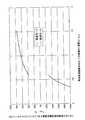
図2〜3は、トロイダル型無段変速機12aの変速比eCVU を−0.435〜−2.3とし、i1 を2.3とし、i2 を2.6とし、ROPG を0.769とし、RIPG を0.909とし、RCG1 及びRCG2 をそれぞれ2とした場合に於ける、上記無段変速装置の特性を示している。このうちの図2は、上記トロイダル型無段変速機12aの変速比eCVU と、このトロイダル型無段変速機12aを組み込んだ無段変速装置全体としての速度比eCVT との関係を、図3は、上記トロイダル型無段変速機12aを通過するトルクTCVU の大きさ及び方向と、このトロイダル型無段変速機12aを組み込んだ無段変速装置全体としての速度比eCVT との関係を、それぞれ示している。
【0036】
このうちの図2から、本例の無段変速装置の場合には、上記トロイダル型無段変速機12aの変速比eCVU を1.95程度にする事で、前記入力軸29を回転させたまま、前記出力軸34を停止させられる事が分かる。又、上記トロイダル型無段変速機12aの変速比eCVU が0.4程度で前記低速用、高速用両クラッチ27a、28aの断接を行なわせる事により、前記低速モードと前記高速モードとの間で、上記速度比eCVT を不連続にする事なく、滑らかな変速状態を実現できる事も分かる。更に、図3からは、前進状態のほぼ全域に亙って、上記トロイダル型無段変速機12aを通過するトルクTCVU を小さく抑えて、このトロイダル型無段変速機12aの伝達効率及び耐久性を何れも向上させられる事が分かる。
【0037】
【発明の効果】
本発明は、以上に述べた通り構成され作用するので、軸方向寸法が小さく、しかも変速比幅が大きくて、発進装置が不要な無段変速装置を実現できる。この為、FF車等の小型自動車の変速機としての実用性向上に寄与できる。
【図面の簡単な説明】
【図1】本発明の実施の形態の1例を示す略断面図。
【図2】トロイダル型無段変速機の変速比と、このトロイダル型無段変速機を組み込んだ無段変速装置全体としての速度比との関係を示す線図。
【図3】トロイダル型無段変速機を通過するトルクの大きさ及び方向と、このトロイダル型無段変速機を組み込んだ無段変速装置全体としての速度比との関係を示す線図。
【図4】従来から知られているトロイダル型無段変速機の1例を示す断面図。
【図5】従来から知られている無段変速装置の1例を示す略断面図。
【符号の説明】
1 入力軸
2 入力側ディスク
3 ボールスプライン
4 出力歯車
5、5a 出力側ディスク
6 パワーローラ
7 トラニオン
8 支持軸
9 円筒部
10 駆動軸
11 押圧装置
12、12a トロイダル型無段変速機
13 遊星歯車式変速機
14 キャリア
15a、15b 遊星歯車素子
16 第一の伝達軸
17a、17b 太陽歯車
18 第二の伝達軸
19 中空回転軸
20 太陽歯車
21 遊星歯車素子
22 リング歯車
23 第二のキャリア
24a、24b 遊星歯車素子
25 出力軸
26 第二のリング歯車
27、27a 低速用クラッチ
28、28a 高速用クラッチ
29 入力軸
30 回転伝達軸
31 第一の遊星歯車式変速機
32 第二の遊星歯車式変速機
33 第二の回転伝達軸
34 出力軸
35 第一の動力伝達機構
36 第二の動力伝達機構
37 第三の動力伝達機構
38 ダンパ継手
39 歯車
40 第一の太陽歯車
41 第一のリング歯車
42 第一のキャリア
43 第一の遊星歯車
44 第二の太陽歯車
45 第二のリング歯車
46 第二のキャリア
47 第二の遊星歯車
48 中空回転軸
49 歯車
50 歯車
51 歯車
52 歯車
53 第二の中空回転軸
54 歯車
55 歯車
56 歯車
57 歯車
58 デファレンシャルギヤ
59 アクスル軸[0001]
BACKGROUND OF THE INVENTION
The present invention relates to an improvement of a continuously variable transmission incorporating a toroidal type continuously variable transmission used as an automatic transmission for an automobile.
[0002]
[Prior art]
The use of a toroidal-type continuously variable transmission as shown in FIG. 4 as an automatic transmission for automobiles has been studied and implemented in part. This toroidal type continuously variable transmission is called a double cavity type, and supports input-
[0003]
A plurality (usually 2 to 3) of
[0004]
During the operation of the toroidal type continuously variable transmission as described above, one input side disk 2 (left side in FIG. 4) is connected to a loading cam type as shown in FIG. Is rotationally driven via a
[0005]
When the rotational speed of the
[0006]
Furthermore, when the toroidal type continuously variable transmission configured and operated as described above is incorporated in an actual continuously variable transmission for an automobile, it is possible to configure a continuously variable transmission in combination with a planetary gear mechanism. As described in (2) to (2), various proposals have been made conventionally. FIG. 5 shows the one described in
[0007]
The planetary
[0008]
On the other hand, the
[0009]
In the case of the continuously variable transmission shown in FIG. 5 as described above, in the so-called low speed mode state in which the
[0010]
Incidentally, during acceleration or constant speed running in such a low speed mode state, torque passing through the toroidal type continuously
[0011]
On the other hand, in the so-called high speed mode state in which the
The torque passing through the toroidal-type continuously
[0012]
Although not shown,
[0013]
[Patent Document 1]
JP 2000-220719 A
[Patent Document 2]
Japanese Patent No. 2778038
[0014]
[Problems to be solved by the invention]
As described above, the conventionally proposed continuously variable transmission has a toroidal continuously variable transmission and a planetary gear transmission arranged coaxially, so that the axial dimension of the continuously variable transmission as a whole is small. Bulky. For this reason, it is not suitable as a transmission for a front engine front wheel drive vehicle (FF vehicle) that is widely spread mainly in small vehicles. In the case of the invention described in
[0015]
Furthermore, in the case of the structure described in
In view of such circumstances, the continuously variable transmission of the present invention has been invented to realize a structure capable of reducing the axial dimension and realizing an infinite gear ratio.
[0016]
[Means for Solving the Problems]
A continuously variable transmission of the present invention includes an input shaft, a toroidal continuously variable transmission, a rotation transmission shaft, first and second planetary gear transmissions, a second rotation transmission shaft, and an output shaft. , First and second power transmission mechanisms, and a switching mechanism.
Of these, the toroidal continuously variable transmission is arranged concentrically with the input shaft. The rotation transmission shaft is parallel to the input shaft.
The first and second planetary gear type transmissions are arranged concentrically around the rotation transmission shaft.
The second rotation transmission shaft is arranged in parallel with the input shaft and the rotation transmission shaft.
The output shaft is arranged concentrically with the rotation transmission shaft.
In addition, the first power transmission mechanism can rotate the input shaft.The first planetary gear type transmission It transmits to the 1st ring gearwheel which comprises.
The second power transmission mechanism transmits the rotation of the input shaft to the second carrier constituting the second planetary gear type transmission via the second rotation transmission shaft. is there.
The switching mechanism is for switching the state of power transmission between the input shaft and the output shaft through the first and second power transmission mechanisms.
Then, power transmission through the first power transmission mechanism is performed, and power transmission through the second power transmission mechanism is cut off. The output shaft can be stopped while the input shaft is rotated.
[0017]
[Action]
The continuously variable transmission of the present invention configured as described above is arranged so that the central axis of the toroidal type continuously variable transmission is shifted from the central axes of the first and second planetary gear transmissions. The axial dimension of the entire step transmission can be reduced. In addition, since the output shaft can be stopped while the input shaft is rotated and a state where the transmission gear ratio is infinite can be realized, there is no need to separately install a starting device such as a torque converter. Furthermore, the number of clutches constituting the mode switching mechanism can be reduced. Therefore, it is possible to realize a continuously variable transmission that is small and has good transmission efficiency.
[0018]
DETAILED DESCRIPTION OF THE INVENTION
FIG. 1 shows an example of an embodiment of the present invention. The continuously variable transmission of this example includes an input shaft 29, a toroidal-type continuously variable transmission 12a, a rotation transmission shaft 30, first and second
[0019]
The toroidal-type continuously variable transmission 12a is constructed similarly to the conventional structure shown in FIG. 4 and includes a pair of input-
[0020]
The rotation transmission shaft 30 is disposed in parallel with the input shaft 29. The
[0021]
In order to constitute the first planetary
[0022]
The
[0023]
On the other hand, in order to constitute the second planetary gear type transmission 32, a
[0024]
The second
[0025]
Further, the tip end portion (left end portion in FIG. 1) of the output shaft 34 is connected to a
[0026]
The operation of the continuously variable transmission of this example configured as described above is as follows. First, in the low speed mode state in which the low speed clutch 27a is connected and the high speed clutch 28a is disconnected, the rotation of the input shaft 29 passes through the following two routes (1) and (2). The first planetary
(1) Input shaft 29 →
(2) Input shaft 29 → toroidal continuously variable transmission 12a → output gear 4 →
[0027]
In this state, the differential component between the
[0028]
The speed ratio e of the continuously variable transmission as a whole in such a low-speed mode state.CVT Is represented by the following equation (1).
[Expression 1]
eCVU : Gear ratio of the toroidal-type continuously variable transmission 12a
i1 : Ratio of the number of teeth of the
ROPG : Reduction ratio of the third power transmission mechanism 37 constituted by the
RIPG : Reduction ratio of the first power transmission mechanism 35 configured by the
[0029]
In such a low speed mode state, the transmission ratio e of the toroidal-type continuously variable transmission 12a.CVU By setting the value to the value expressed by the following equation (2), it is possible to realize a so-called infinite state in which the output shaft 34 is stopped while the input shaft 29 is rotated.
[Expression 2]
[0030]
On the other hand, in the high speed mode state in which the low speed clutch 27a is disconnected and the high speed clutch 28a is connected, the rotation of the input shaft 29 is the following two routes (3) and (4). And is transmitted to the
(3) Input shaft 29 →
(4) Input shaft 29 → toroidal continuously variable transmission 12a → output gear 4 →
[0031]
In this state, the differential component between the
[0032]
The speed ratio e of the continuously variable transmission as a whole in such a high-speed mode state.CVT Is represented by the following equation (3).
[Equation 3]
i2 : Ratio of the number of teeth of the
RCG1 : Reduction ratio of transmission part by both
RCG2 : Reduction ratio of transmission part by both
[0033]
As is clear from the equation (3), the gear ratio e of the toroidal type continuously variable transmission 12a is obtained in the high speed mode state.CVU The speed ratio e of the continuously variable transmission as a whole increases as the speed increases.CVT Also changes to the speed increasing side.
In such a high-speed mode, the torque transmitted from the engine to the input shaft 29 is Te Then, the torque T passing through the toroidal-type continuously variable transmission 12aCVU Is represented by the following equation (4). The meanings of the symbols in the formula are as described above. Further, the gear ratio e of the toroidal type continuously variable transmission 12a in the equation (4).CVU The value of is negative.
[Expression 4]
[0034]
Further, as is clear from the above formula (3) and the above formula (1), the reduction ratio R of the transmission portion by the
[0035]
2 to 3 show the gear ratio e of the toroidal type continuously variable transmission 12a.CVU Is -0.435 to -2.3, i1 Is 2.3 and i2 Is 2.6 and ROPG Is 0.769 and RIPG Is 0.909 and RCG1 And RCG2 The characteristics of the continuously variable transmission are shown in the case where each is 2. Of these, FIG. 2 shows the gear ratio e of the toroidal-type continuously variable transmission 12a.CVU And a speed ratio e as a whole continuously variable transmission incorporating the toroidal type continuously variable transmission 12a.CVT FIG. 3 shows the relationship between the torque T passing through the toroidal continuously variable transmission 12a.CVU And the speed ratio e of the continuously variable transmission incorporating the toroidal continuously variable transmission 12a.CVT The relationship is shown respectively.
[0036]
From FIG. 2, in the case of the continuously variable transmission of this example, the transmission ratio e of the toroidal-type continuously variable transmission 12 a is described.CVU It is understood that the output shaft 34 can be stopped while the input shaft 29 is rotated by setting the value to about 1.95. Further, the transmission ratio e of the toroidal type continuously variable transmission 12a.CVU Is approximately 0.4 and the speed ratio e between the low speed mode and the high speed mode is established by connecting and disconnecting the low speed and high speed clutches 27a, 28a.CVT It can also be seen that a smooth shifting state can be realized without discontinuity. Further, from FIG. 3, the torque T passing through the toroidal type continuously variable transmission 12a over almost the entire region of the forward movement state.CVU It can be seen that both the transmission efficiency and durability of the toroidal-type continuously variable transmission 12a can be improved by keeping the tom small.
[0037]
【The invention's effect】
Since the present invention is configured and operates as described above, it is possible to realize a continuously variable transmission having a small axial dimension and a large speed ratio width and requiring no starting device. For this reason, it can contribute to the improvement of practicality as a transmission of a small vehicle such as an FF vehicle.
[Brief description of the drawings]
FIG. 1 is a schematic cross-sectional view showing an example of an embodiment of the present invention.
FIG. 2 is a diagram showing the relationship between the transmission ratio of the toroidal type continuously variable transmission and the speed ratio of the entire continuously variable transmission incorporating this toroidal type continuously variable transmission.
FIG. 3 is a diagram showing the relationship between the magnitude and direction of torque passing through a toroidal continuously variable transmission and the speed ratio of the entire continuously variable transmission incorporating this toroidal continuously variable transmission.
FIG. 4 is a cross-sectional view showing an example of a conventionally known toroidal continuously variable transmission.
FIG. 5 is a schematic cross-sectional view showing an example of a conventionally known continuously variable transmission.
[Explanation of symbols]
1 Input shaft
2 Input disk
3 Ball spline
4 Output gear
5, 5a Output disk
6 Power roller
7 Trunnion
8 Support shaft
9 Cylindrical part
10 Drive shaft
11 Pressing device
12, 12a Toroidal type continuously variable transmission
13 Planetary gear type transmission
14 Career
15a, 15b planetary gear element
16 First transmission shaft
17a, 17b Sun gear
18 Second transmission shaft
19 Hollow rotating shaft
20 Sun gear
21 Planetary gear element
22 Ring gear
23 Second career
24a, 24b planetary gear elements
25 Output shaft
26 Second ring gear
27, 27a Low speed clutch
28, 28a High speed clutch
29 Input shaft
30 Rotation transmission shaft
31 First planetary gear type transmission
32 Second planetary gear type transmission
33 Second rotation transmission shaft
34 Output shaft
35 First power transmission mechanism
36 Second power transmission mechanism
37 Third power transmission mechanism
38 Damper fitting
39 Gear
40 The first sun gear
41 First ring gear
42 First career
43 First planetary gear
44 Second Sun Gear
45 Second ring gear
46 Second career
47 Second planetary gear
48 hollow rotating shaft
49 Gear
50 gears
51 gears
52 Gear
53 Second hollow rotating shaft
54 Gear
55 Gear
56 gears
57 Gear
58 differential gear
59 Axle axle
Claims (6)
Translated fromJapanese上記トロイダル型無段変速機は、上記入力軸と共に回転する入力側ディスクと、この入力側ディスクと同心に且つこの入力側ディスクに対する相対回転を自在に支持された出力側ディスクと、これら両ディスク同士の間に挟持された複数個のパワーローラとを備えたものであり、
上記回転伝達軸は、上記出力側ディスクにより第三の動力伝達機構を介して回転駆動されるものであり、
上記第一の遊星歯車式変速機は、上記回転伝達軸と共に回転する第一の太陽歯車と、この第一の太陽歯車の周囲に回転自在に支持された第一のリング歯車と、これら第一の太陽歯車及び第一のリング歯車と同心に且つこれら第一の太陽歯車及び第一のリング歯車に対する相対回転を自在に支持された第一のキャリアと、それぞれがこの第一のキャリアに回転自在に支持された状態で、上記第一の太陽歯車と第一のリング歯車とに噛合した複数個の第一の遊星歯車とを備えたものであり、
上記第二の遊星歯車式変速機は、上記回転伝達軸と共に回転する第二の太陽歯車と、この第二の太陽歯車の周囲に回転自在に支持されて上記第一のキャリアと共に回転する第二のリング歯車と、これら第二の太陽歯車及び第二のリング歯車と同心に且つこれら第二の太陽歯車及び第二のリング歯車に対する相対回転を自在に支持された第二のキャリアと、それぞれがこの第二のキャリアに回転自在に支持された状態で、上記第二の太陽歯車と第二のリング歯車とに噛合した複数個の第二の遊星歯車とを備えたものであり、
上記第一の動力伝達機構は、上記入力軸の回転を上記第一のリング歯車に伝達するものであり、
上記第二の動力伝達機構は、上記入力軸の回転を、上記第二の回転伝達軸を介して上記第二のキャリアに伝達するものであり、
上記切換機構は、上記第一の動力伝達機構と上記第二の動力伝達機構とのうちの何れか一方の動力伝達機構を通じての動力伝達を行なわせ、他方の動力伝達機構を通じての動力伝達を遮断するものであり、
上記切換機構が上記第一の動力伝達機構を通じての動力伝達を行なわせ、上記第二の動力伝達機構を通じての動力伝達を遮断した状態で、上記トロイダル型無段変速機の変速比の調節に基づき、上記入力軸を回転させたまま上記出力軸を停止可能とした、
請求項1に記載した無段変速装置。An input shaft, a toroidal continuously variable transmission arranged concentrically with the input shaft, a rotation transmission shaft parallel to the input shaft, and a single pinion arranged concentrically around the rotation transmission shaft. First and second planetary gear type transmissions, a second rotation transmission shaft arranged parallel to the input shaft and the rotation transmission shaft, and an output shaft arranged concentrically with the rotation transmission shaft And a first and second power transmission mechanism, and a switching mechanism for switching the state of power transmission between the input shaft and the output shaft through the first and second power transmission mechanisms,
The toroidal-type continuously variable transmission includes an input-side disk that rotates together with the input shaft, an output-side disk that is concentric with the input-side disk and that is supported to freely rotate relative to the input-side disk, and And a plurality of power rollers sandwiched between
The rotation transmission shaft is rotationally driven by the output side disk via a third power transmission mechanism,
The first planetary gear type transmission includes a first sun gear that rotates together with the rotation transmission shaft, a first ring gear that is rotatably supported around the first sun gear, A first carrier that is concentric with the first sun gear and the first ring gear and is supported for relative rotation with respect to the first sun gear and the first ring gear. A plurality of first planetary gears meshed with the first sun gear and the first ring gear.
The second planetary gear type transmission includes a second sun gear that rotates together with the rotation transmission shaft, and a second sun gear that is rotatably supported around the second sun gear and rotates together with the first carrier. And a second carrier concentrically supported by the second sun gear and the second ring gear and capable of freely rotating relative to the second sun gear and the second ring gear. A plurality of second planetary gears meshed with the second sun gear and the second ring gear in a state of being rotatably supported by the second carrier,
The first power transmission mechanism transmits the rotation of the input shaft to the first ring gear,
The second power transmission mechanism transmits the rotation of the input shaft to the second carrier via the second rotation transmission shaft,
The switching mechanism performs power transmission through one of the first power transmission mechanism and the second power transmission mechanism, and interrupts power transmission through the other power transmission mechanism. Is what
Based on the adjustment of the gear ratio of the toroidal continuously variable transmission in a state where the switching mechanism performs power transmission through the first power transmission mechanism and interrupts power transmission through the second power transmission mechanism. The output shaft can be stopped while the input shaft is rotated.
The continuously variable transmission according to claim 1.
Priority Applications (2)
| Application Number | Priority Date | Filing Date | Title |
|---|---|---|---|
| JP2002344837AJP3832424B2 (en) | 2002-11-28 | 2002-11-28 | Continuously variable transmission |
| US10/721,274US6958029B2 (en) | 2002-11-28 | 2003-11-26 | Continuously variable transmission apparatus |
Applications Claiming Priority (1)
| Application Number | Priority Date | Filing Date | Title |
|---|---|---|---|
| JP2002344837AJP3832424B2 (en) | 2002-11-28 | 2002-11-28 | Continuously variable transmission |
Publications (3)
| Publication Number | Publication Date |
|---|---|
| JP2004176832A JP2004176832A (en) | 2004-06-24 |
| JP2004176832A5 JP2004176832A5 (en) | 2005-10-20 |
| JP3832424B2true JP3832424B2 (en) | 2006-10-11 |
Family
ID=32706168
Family Applications (1)
| Application Number | Title | Priority Date | Filing Date |
|---|---|---|---|
| JP2002344837AExpired - Fee RelatedJP3832424B2 (en) | 2002-11-28 | 2002-11-28 | Continuously variable transmission |
Country Status (2)
| Country | Link |
|---|---|
| US (1) | US6958029B2 (en) |
| JP (1) | JP3832424B2 (en) |
Families Citing this family (46)
| Publication number | Priority date | Publication date | Assignee | Title |
|---|---|---|---|---|
| US7011600B2 (en) | 2003-02-28 | 2006-03-14 | Fallbrook Technologies Inc. | Continuously variable transmission |
| WO2006041718A2 (en) | 2004-10-05 | 2006-04-20 | Fallbrook Technologies, Inc. | Continuously variable transmission |
| WO2007014706A1 (en)* | 2005-08-02 | 2007-02-08 | Gloeckler Dieter | Transmission unit, particularly multirange transmission |
| WO2007070167A2 (en) | 2005-10-28 | 2007-06-21 | Fallbrook Technologies Inc. | Electromotive drives |
| PL1954959T3 (en) | 2005-11-22 | 2013-10-31 | Fallbrook Ip Co Llc | Continuously variable transmission |
| CN102221073B (en) | 2005-12-09 | 2013-03-27 | 福博科技术公司 | Continuously variable transmission |
| EP1811202A1 (en) | 2005-12-30 | 2007-07-25 | Fallbrook Technologies, Inc. | A continuously variable gear transmission |
| US7882762B2 (en) | 2006-01-30 | 2011-02-08 | Fallbrook Technologies Inc. | System for manipulating a continuously variable transmission |
| US20070238568A1 (en)* | 2006-04-10 | 2007-10-11 | Derek Lahr | Cam-based infinitely variable transmission |
| CN102269055B (en) | 2006-06-26 | 2013-08-28 | 福博科技术公司 | Continuously variable transmission |
| JP4867540B2 (en)* | 2006-09-20 | 2012-02-01 | 日本精工株式会社 | Continuously variable transmission |
| PL2089642T3 (en) | 2006-11-08 | 2013-09-30 | Fallbrook Ip Co Llc | Clamping force generator |
| EP2125469A2 (en) | 2007-02-01 | 2009-12-02 | Fallbrook Technologies Inc. | System and methods for control of transmission and/or prime mover |
| US20100093479A1 (en) | 2007-02-12 | 2010-04-15 | Fallbrook Technologies Inc. | Continuously variable transmissions and methods therefor |
| TWI461615B (en) | 2007-02-16 | 2014-11-21 | Fallbrook Ip Co Llc | Infinitely variable transmissions, continuously variable transmissions, methods, assemblies, subassemblies, and components therefor |
| EP2142826B1 (en) | 2007-04-24 | 2015-10-28 | Fallbrook Intellectual Property Company LLC | Electric traction drives |
| US8641577B2 (en) | 2007-06-11 | 2014-02-04 | Fallbrook Intellectual Property Company Llc | Continuously variable transmission |
| CN103697120B (en) | 2007-07-05 | 2017-04-12 | 福博科技术公司 | Continuously variable transmission |
| GB2452710A (en)* | 2007-09-11 | 2009-03-18 | Forbes George De Brie Perry | Toric transmission with epicyclic output drive |
| AU2008303081C1 (en)* | 2007-09-28 | 2013-01-31 | Vrt Innovations Ltd | A variable transmission |
| CN103939602B (en) | 2007-11-16 | 2016-12-07 | 福博科知识产权有限责任公司 | Controllers for variable speed drives |
| US7878935B2 (en)* | 2007-11-26 | 2011-02-01 | Derek Lahr | Continuously variable transmission with external cam |
| US8321097B2 (en) | 2007-12-21 | 2012-11-27 | Fallbrook Intellectual Property Company Llc | Automatic transmissions and methods therefor |
| US8313405B2 (en) | 2008-02-29 | 2012-11-20 | Fallbrook Intellectual Property Company Llc | Continuously and/or infinitely variable transmissions and methods therefor |
| US8317651B2 (en) | 2008-05-07 | 2012-11-27 | Fallbrook Intellectual Property Company Llc | Assemblies and methods for clamping force generation |
| CN102112778B (en) | 2008-06-06 | 2013-10-16 | 福博科技术公司 | Infinitely variable transmission, continuously variable transmission, methods, assemblies, subassemblies and components therefor |
| EP2304272B1 (en) | 2008-06-23 | 2017-03-08 | Fallbrook Intellectual Property Company LLC | Continuously variable transmission |
| CA2732668C (en) | 2008-08-05 | 2017-11-14 | Fallbrook Technologies Inc. | Methods for control of transmission and prime mover |
| US8469856B2 (en) | 2008-08-26 | 2013-06-25 | Fallbrook Intellectual Property Company Llc | Continuously variable transmission |
| US8167759B2 (en) | 2008-10-14 | 2012-05-01 | Fallbrook Technologies Inc. | Continuously variable transmission |
| ES2439647T3 (en) | 2009-04-16 | 2014-01-24 | Fallbrook Intellectual Property Company Llc | Stator set and speed change mechanism for a continuously variable transmission |
| GB2470717B (en) | 2009-05-19 | 2015-04-22 | Torotrak Dev Ltd | Continuously variable ratio transmission |
| US8512195B2 (en) | 2010-03-03 | 2013-08-20 | Fallbrook Intellectual Property Company Llc | Infinitely variable transmissions, continuously variable transmissions, methods, assemblies, subassemblies, and components therefor |
| US8888643B2 (en) | 2010-11-10 | 2014-11-18 | Fallbrook Intellectual Property Company Llc | Continuously variable transmission |
| AU2012240435B2 (en) | 2011-04-04 | 2016-04-28 | Fallbrook Intellectual Property Company Llc | Auxiliary power unit having a continuously variable transmission |
| JP5702270B2 (en)* | 2011-12-19 | 2015-04-15 | 本田技研工業株式会社 | transmission |
| CN104302949B (en) | 2012-01-23 | 2017-05-03 | 福博科知识产权有限责任公司 | Infinitely variable continuously variable transmission, continuously variable continuously variable transmission, method, assembly, subassembly, and parts thereof |
| KR20130117091A (en)* | 2012-04-17 | 2013-10-25 | 주식회사 만도 | Electronic parking brake |
| KR102433297B1 (en) | 2013-04-19 | 2022-08-16 | 폴브룩 인텔렉츄얼 프로퍼티 컴퍼니 엘엘씨 | Continuously variable transmission |
| JP2017537285A (en)* | 2014-12-08 | 2017-12-14 | ダナ リミテッド | Three-mode planetary mechanism continuously variable transmission for front wheel drive and rear wheel drive |
| US10047861B2 (en) | 2016-01-15 | 2018-08-14 | Fallbrook Intellectual Property Company Llc | Systems and methods for controlling rollback in continuously variable transmissions |
| KR102364407B1 (en) | 2016-03-18 | 2022-02-16 | 폴브룩 인텔렉츄얼 프로퍼티 컴퍼니 엘엘씨 | continuously variable transmission system and method |
| KR102494648B1 (en)* | 2016-04-12 | 2023-01-31 | 알리손 트랜스미션, 인크. | continuously variable gearbox |
| US10023266B2 (en) | 2016-05-11 | 2018-07-17 | Fallbrook Intellectual Property Company Llc | Systems and methods for automatic configuration and automatic calibration of continuously variable transmissions and bicycles having continuously variable transmissions |
| US11215268B2 (en) | 2018-11-06 | 2022-01-04 | Fallbrook Intellectual Property Company Llc | Continuously variable transmissions, synchronous shifting, twin countershafts and methods for control of same |
| WO2020176392A1 (en) | 2019-02-26 | 2020-09-03 | Fallbrook Intellectual Property Company Llc | Reversible variable drives and systems and methods for control in forward and reverse directions |
Family Cites Families (16)
| Publication number | Priority date | Publication date | Assignee | Title |
|---|---|---|---|---|
| US4856371A (en)* | 1987-03-12 | 1989-08-15 | Tractiontec Corporation | Traction drive transmission system |
| JP2929592B2 (en) | 1987-12-24 | 1999-08-03 | 日本精工株式会社 | Toroidal continuously variable transmission |
| DE58900243D1 (en)* | 1988-03-30 | 1991-10-02 | Zahnradfabrik Friedrichshafen | POWERTRAIN TRANSMISSION WITH CONTINUOUSLY ADJUSTABLE GEARING. |
| JP2778038B2 (en) | 1988-06-10 | 1998-07-23 | 日本精工株式会社 | Toroidal continuously variable transmission |
| DE4021643A1 (en)* | 1990-07-06 | 1992-01-16 | Claas Ohg | HYDROSTATIC-POWER-BRANCHED MULTI-SPEED POWERTRAIN GEARBOX |
| GB9026830D0 (en) | 1990-12-11 | 1991-01-30 | Fellows Thomas G | Improvements in or relating to continuously-variable-ratio transmissions of toroidal-race rolling-traction type |
| JPH09210175A (en) | 1996-01-31 | 1997-08-12 | Nissan Motor Co Ltd | Transmission ratio infinitely variable transmission |
| JP3500826B2 (en) | 1996-01-31 | 2004-02-23 | 日産自動車株式会社 | Transmission control device for infinitely variable speed ratio continuously variable transmission |
| JP3711688B2 (en)* | 1997-03-22 | 2005-11-02 | マツダ株式会社 | Toroidal continuously variable transmission |
| US6171210B1 (en)* | 1997-08-12 | 2001-01-09 | Nsk Ltd. | Toroidal type continuous variable transmission system |
| JP2000120822A (en)* | 1998-10-21 | 2000-04-28 | Nsk Ltd | Continuously variable transmission |
| JP4062809B2 (en)* | 1999-02-03 | 2008-03-19 | 日本精工株式会社 | Continuously variable transmission |
| US6059685A (en)* | 1999-05-06 | 2000-05-09 | Ford Global Technologies, Inc. | Coaxial traction drive automatic transmission for automotive vehicles |
| DE10021912A1 (en)* | 2000-05-05 | 2001-11-08 | Daimler Chrysler Ag | Drive train for motor vehicle has second planet wheel with diameter such that for stepping up of variable speed gear contact point of second planet wheel with driven element corresponds to center of rotation of second planet wheel |
| US6358178B1 (en)* | 2000-07-07 | 2002-03-19 | General Motors Corporation | Planetary gearing for a geared neutral traction drive |
| JP2003097669A (en)* | 2001-09-27 | 2003-04-03 | Jatco Ltd | Torque split type continuously variable transmission with infinite gear ratio |
- 2002
- 2002-11-28JPJP2002344837Apatent/JP3832424B2/ennot_activeExpired - Fee Related
- 2003
- 2003-11-26USUS10/721,274patent/US6958029B2/ennot_activeExpired - Lifetime
Also Published As
| Publication number | Publication date |
|---|---|
| US6958029B2 (en) | 2005-10-25 |
| US20040142785A1 (en) | 2004-07-22 |
| JP2004176832A (en) | 2004-06-24 |
Similar Documents
| Publication | Publication Date | Title |
|---|---|---|
| JP3832424B2 (en) | Continuously variable transmission | |
| JP3896958B2 (en) | Continuously variable transmission | |
| US8257217B2 (en) | Infinitely variable transmission with offset output shaft | |
| JP2002048213A (en) | Transmission with continuously variable transmission | |
| EP1188956A2 (en) | Infinitely variable transmission | |
| JP2004232776A (en) | Toroidal continuously variable transmission | |
| JP4151300B2 (en) | Continuously variable transmission | |
| JPH11280867A (en) | Continuously variable transmission | |
| JPH10196759A (en) | Continuously variable transmission | |
| JP2006308039A (en) | Continuously variable transmission | |
| JP5061647B2 (en) | Continuously variable transmission | |
| JP4029706B2 (en) | Continuously variable transmission | |
| JP3702598B2 (en) | Half toroidal continuously variable transmission | |
| JPH11236955A (en) | Continuously variable transmission | |
| JP4288987B2 (en) | Continuously variable transmission | |
| JPH11108149A (en) | Continuously variable transmission | |
| JP2003314661A (en) | Continuously variable transmission | |
| JP4178848B2 (en) | Continuously variable transmission | |
| JP4696770B2 (en) | Continuously variable transmission | |
| JP2004239301A (en) | Continuously variable transmission | |
| JP3164081B2 (en) | Transmission ratio infinitely variable transmission | |
| JP2001289303A (en) | Continuously variable transmission | |
| JP2004239302A (en) | Continuously variable transmission | |
| JP4144166B2 (en) | Continuously variable transmission for pumping pump or generator | |
| JP2007051695A (en) | Vehicle drive device |
Legal Events
| Date | Code | Title | Description |
|---|---|---|---|
| A521 | Request for written amendment filed | Free format text:JAPANESE INTERMEDIATE CODE: A523 Effective date:20050628 | |
| A621 | Written request for application examination | Free format text:JAPANESE INTERMEDIATE CODE: A621 Effective date:20050628 | |
| A977 | Report on retrieval | Free format text:JAPANESE INTERMEDIATE CODE: A971007 Effective date:20060524 | |
| TRDD | Decision of grant or rejection written | ||
| A01 | Written decision to grant a patent or to grant a registration (utility model) | Free format text:JAPANESE INTERMEDIATE CODE: A01 Effective date:20060627 | |
| A61 | First payment of annual fees (during grant procedure) | Free format text:JAPANESE INTERMEDIATE CODE: A61 Effective date:20060710 | |
| R150 | Certificate of patent or registration of utility model | Free format text:JAPANESE INTERMEDIATE CODE: R150 | |
| FPAY | Renewal fee payment (event date is renewal date of database) | Free format text:PAYMENT UNTIL: 20100728 Year of fee payment:4 | |
| FPAY | Renewal fee payment (event date is renewal date of database) | Free format text:PAYMENT UNTIL: 20110728 Year of fee payment:5 | |
| FPAY | Renewal fee payment (event date is renewal date of database) | Free format text:PAYMENT UNTIL: 20110728 Year of fee payment:5 | |
| FPAY | Renewal fee payment (event date is renewal date of database) | Free format text:PAYMENT UNTIL: 20120728 Year of fee payment:6 | |
| FPAY | Renewal fee payment (event date is renewal date of database) | Free format text:PAYMENT UNTIL: 20120728 Year of fee payment:6 | |
| FPAY | Renewal fee payment (event date is renewal date of database) | Free format text:PAYMENT UNTIL: 20130728 Year of fee payment:7 | |
| LAPS | Cancellation because of no payment of annual fees |