JP3832338B2 - Electrostrictive polymer actuator - Google Patents
Electrostrictive polymer actuatorDownload PDFInfo
- Publication number
- JP3832338B2 JP3832338B2JP2001392700AJP2001392700AJP3832338B2JP 3832338 B2JP3832338 B2JP 3832338B2JP 2001392700 AJP2001392700 AJP 2001392700AJP 2001392700 AJP2001392700 AJP 2001392700AJP 3832338 B2JP3832338 B2JP 3832338B2
- Authority
- JP
- Japan
- Prior art keywords
- electrodes
- elastic material
- actuator
- polymer actuator
- peripheral side
- Prior art date
- Legal status (The legal status is an assumption and is not a legal conclusion. Google has not performed a legal analysis and makes no representation as to the accuracy of the status listed.)
- Expired - Fee Related
Links
Images


Classifications
- F—MECHANICAL ENGINEERING; LIGHTING; HEATING; WEAPONS; BLASTING
- F16—ENGINEERING ELEMENTS AND UNITS; GENERAL MEASURES FOR PRODUCING AND MAINTAINING EFFECTIVE FUNCTIONING OF MACHINES OR INSTALLATIONS; THERMAL INSULATION IN GENERAL
- F16J—PISTONS; CYLINDERS; SEALINGS
- F16J3/00—Diaphragms; Bellows; Bellows pistons
- F16J3/02—Diaphragms
- H—ELECTRICITY
- H02—GENERATION; CONVERSION OR DISTRIBUTION OF ELECTRIC POWER
- H02N—ELECTRIC MACHINES NOT OTHERWISE PROVIDED FOR
- H02N1/00—Electrostatic generators or motors using a solid moving electrostatic charge carrier
- H02N1/002—Electrostatic motors
- F—MECHANICAL ENGINEERING; LIGHTING; HEATING; WEAPONS; BLASTING
- F04—POSITIVE - DISPLACEMENT MACHINES FOR LIQUIDS; PUMPS FOR LIQUIDS OR ELASTIC FLUIDS
- F04B—POSITIVE-DISPLACEMENT MACHINES FOR LIQUIDS; PUMPS
- F04B43/00—Machines, pumps, or pumping installations having flexible working members
- F04B43/0009—Special features
- F04B43/0054—Special features particularities of the flexible members
- F—MECHANICAL ENGINEERING; LIGHTING; HEATING; WEAPONS; BLASTING
- F04—POSITIVE - DISPLACEMENT MACHINES FOR LIQUIDS; PUMPS FOR LIQUIDS OR ELASTIC FLUIDS
- F04B—POSITIVE-DISPLACEMENT MACHINES FOR LIQUIDS; PUMPS
- F04B43/00—Machines, pumps, or pumping installations having flexible working members
- F04B43/02—Machines, pumps, or pumping installations having flexible working members having plate-like flexible members, e.g. diaphragms
- F04B43/04—Pumps having electric drive
- H—ELECTRICITY
- H10—SEMICONDUCTOR DEVICES; ELECTRIC SOLID-STATE DEVICES NOT OTHERWISE PROVIDED FOR
- H10N—ELECTRIC SOLID-STATE DEVICES NOT OTHERWISE PROVIDED FOR
- H10N30/00—Piezoelectric or electrostrictive devices
- H10N30/20—Piezoelectric or electrostrictive devices with electrical input and mechanical output, e.g. functioning as actuators or vibrators
- H10N30/204—Piezoelectric or electrostrictive devices with electrical input and mechanical output, e.g. functioning as actuators or vibrators using bending displacement, e.g. unimorph, bimorph or multimorph cantilever or membrane benders
- H10N30/2047—Membrane type
Landscapes
- Engineering & Computer Science (AREA)
- General Engineering & Computer Science (AREA)
- Mechanical Engineering (AREA)
- Reciprocating Pumps (AREA)
- General Electrical Machinery Utilizing Piezoelectricity, Electrostriction Or Magnetostriction (AREA)
Description
Translated fromJapanese【0001】
【発明の属する技術分野】
本発明は電歪ポリマーを用いたアクチュエータに関するものである。
【0002】
【従来の技術】
超小型機器に用いるアクチュエータとして、圧電素子を用いたものと電歪ポリマーを用いたものとが知られている。前者は厚み方向に分極処理を行ったシート状の圧電材料の両面に導電性伸縮材料からなる電極を配して、圧電逆効果により伸縮させるものであり、分極方向と同極性の電圧の印加によって分極方向に伸び、直交方向に縮む性質を有している。後者はシリコンゴムやアクリル等のシート状の絶縁性伸縮材料からなる伸縮部の両面に導電性伸縮材料からなる電極を配して、誘電分極によって延伸させるもので、電圧の印加時、電極間方向に縮み、直交する方向に伸びる性質を有している。
【0003】
【発明が解決しようとする課題】
圧電素子を用いたアクチュエータは、特開昭59−200081号公報などに示されているように、ダイヤフラムポンプのダイヤフラム駆動用等として実用化されているが、後者は電圧印加時の動きの管理が困難である上に、電圧印加時の伸縮量が小さかったり発生力が小さいことなどから、未だ実用化されるに至っていない。
【0004】
本発明はこのような点に鑑みなされたものであって、その目的とするところは実用性を有する動きを行わせることができる電歪ポリマーアクチュエータを提供するにある。
【0005】
【課題を解決するための手段】
しかして本発明は、絶縁性伸縮材料からなる伸縮部の両面に導電性伸縮材料からなる電極を配した電歪ポリマーアクチュエータにおいて、リング状の伸縮部の外周側と内周側とに電極を配しているとともに径方向において電極を介して伸縮部を積層し、更に中心に近いほど電極間距離を長く且つ各電極間に印加する電圧を同一としていることに特徴を有しており、またリング状の伸縮部の外周側と内周側とに電極を配しているとともに径方向において電極を介して伸縮部を積層し、更に径方向における各電極間距離を同一とし且つ中心に近いほど電極間に印加する電圧を低くしていることに特徴を有している。電圧印加時に径方向において縮み、軸方向において一様に伸びるものを得ることができる。
【0006】
【発明の実施の形態】
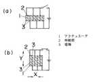
以下本発明を実施の形態の一例に基づいて詳述すると、図1及び図2において、図中2はシリコンゴムやアクリル等の絶縁性伸縮材料からなる伸縮部、3は導電性伸縮材料からなる電極であり、伸縮部2はリング状に形成しているとともに、多数の径の異なるリング状伸縮部2を同心円状に形成しており、これら伸縮部2の間には夫々リング状の電極3を介在させるとともに、最外周面と最内周面にもリング状の電極3を配して、各伸縮部2の内周側と外周側とに夫々電極3が位置するようにしてある。そして図1に示すように、一つおきの電極3を直流電源のプラス側に、残る電極3を直流電源のマイナス側に接続している。
【0007】
このように形成したアクチュエータ1において、電極3,3間に電圧を印加すれば、図1(b)及び図2(b)に示すように、電極3,3間方向である径方向Xにおいて縮むとともに、直交する方向である軸方向Yに伸びる。
【0008】
シート状の伸縮部2の両面に電極3を配していた従来のものに比して、伸縮動作を確実に利用することができるものであり、また同心円状に積層しているために発生する力も大きい。また、印加する電圧値に応じて変位量が変化するために、変位量の調整も容易である。
【0009】
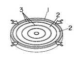
図3は同心円状に積層するにあたり、中心軸に近いほど電極3,3間の距離が長くなるようにするとともに、各電極に印加する電圧を同一にしたもので、径が異なる各リング状伸縮部2の伸縮量をほぼ等しくすることができ、軸方向への均一な延伸機能を得ることができる。
【0010】
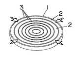
図4に示すように、各電極3,3間距離は同じにするものの、各電極間3,3に印加する電圧は中心軸に近いほど低くなるようにしても、軸方向への均一な延伸機能を得ることができる。
【0011】
なお、各電極3,3間に同じ電圧を印加する場合は、図5に示すように、アクチュエータ1の一面における一つおきの電極3の縁に絶縁性柔軟材料7を塗布するとともに、アクチュエータ1の他面において他の電極の縁に絶縁性柔軟材料7を塗布し、その後、図6に示すようにアクチュエータ1の軸方向両面に導電性伸縮材料8を塗布して外部電極とするとよく、各電極3,3間に異なる電圧を印加する場合は、図5に示す処理を行った後、図7に示すように、アクチュエータ1の一面では先に塗布した絶縁性柔軟材料7間のリング状部分に導電性伸縮材料8を塗布して夫々を外部電極とし、他面では全面に導電性伸縮材料8を塗布して接地用外部電極とすればよい。なお、シェンケル昇圧回路を用いれば、複数の電圧を単一電源より得ることができる。
【0012】
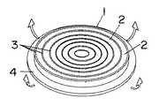
図8に他の実施形態の一例を示す。ここでは伸縮部2の側面を金属薄板4に貼り合わせてユニモルフ構造としている。この場合、電極3,3間に電圧を印加した時、伸縮部2は電極3,3間の方向において縮もうとするのに対して、金属薄板4は縮まないために、アクチュエータ1は金属薄板4を撓ませる(屈曲させる)ものであり、また印加電圧値に応じて屈曲変位量を変えることができる。
【0013】
また金属薄板4の両面に夫々アクチュエータ1,1を貼り合わせてバイモルフ構造とすれば、いずれのアクチュエータ1に電圧を印加するかによって、屈曲方向を変えることができるものであり、結果的に屈曲運動の可動範囲を大きくすることができる。
【0014】
このような構造とする場合、金属薄板4を含めたアクチュエータ1は、自駆動型のダイヤフラムとして用いることができる。
【0015】
なお、上記のような積層型のアクチュエータ1は、図9に示すように、円筒状またはシート状の伸縮部2と電極3とを交互に積層した積層体1’を形成し、その後、該積層体1’を積層方向と平行する方向でスライスすることによって、同一特性の多数のアクチュエータ1を効率良く製造することができる。
【0016】
図10は同心円状に積層したアクチュエータ1を金属薄板4の片面に貼り合わせたものをダイヤフラムとしているダイヤフラムポンプの一例を示しており、吸気口51と排気口52とを備えるとともにこれら吸気口51及び排気口52に逆止弁53,54を組み付けたベース5に、固着手段55によって上記ダイヤフラムの周縁を固定することで、ダイヤフラムとベース5とで囲まれたポンプ室56を形成しており、アクチュエータ1に電圧を印加すれば、ポンプ室56の内容積が小さくなって吐出口52から流体の吐出がなされ、アクチュエータ1への電圧を遮断すれば、アクチュエータ1及び金属薄板4の復帰により、吸気口51からポンプ室56への吸入がなされる。
【0017】
【発明の効果】
以上のように本発明においては、絶縁性伸縮材料からなる伸縮部の両面に導電性伸縮材料からなる電極を配した電歪ポリマーアクチュエータにおいて、リング状の伸縮部の外周側と内周側とに電極を配しているとともに径方向において電極を介して伸縮部を積層しているものであり、電圧印加時に径方向において縮み、軸方向において伸びるものを得ることができるとともに、シート状の伸縮部の両面に電極を配していた従来のものに比して、伸縮動作を確実に利用することができるものであり、また同心円状に積層しているために低印加電圧で高出力を得ることができ、さらには印加する電圧値に応じて変位量が変化するために、変位量の調整も容易なものである。
【0018】
しかも中心に近いほど電極間距離を長くし且つ各電極間に印加する電圧を同一としたり、各電極間距離を同一とし且つ中心に近いほど電極間に印加する電圧を低くしているために、径が異なる各リング状伸縮部
を径方向に積層したものであるとはいえ、軸方向への均一な延伸機能を得ることができる。
【図面の簡単な説明】
【図1】本発明の実施の形態の一例を示すもので、(a)(b)は断面図である。
【図2】(a)(b)は同上の斜視図である。
【図3】同上の他例の斜視図である。
【図4】更に他例の斜視図である。
【図5】外部電極の形成手順を示すもので、(a)は斜視図、(b)は断面図である。
【図6】外部電極の形成手順を示すもので、(a)は斜視図、(b)は断面図である。
【図7】外部電極の形成手順を示すもので、(a)は斜視図、(b)は断面図である。
【図8】同上の更に他例の斜視図である。
【図9】同上のアクチュエータの製造法を示す斜視図である。
【図10】(a)(b)は同上のアクチュエータを用いたダイヤフラムポンプの断面図である。
【符号の説明】
1 アクチュエータ
2 伸縮部
3 電極
4 金属薄板[0001]
BACKGROUND OF THE INVENTION
The present invention relates to anactuator using an electrostrictive polymer.
[0002]
[Prior art]
As actuators used in microminiature devices, those using piezoelectric elements and those using electrostrictive polymers are known. In the former, electrodes made of a conductive stretch material are arranged on both sides of a sheet-like piezoelectric material that has been polarized in the thickness direction, and stretched by the piezoelectric reverse effect. By applying a voltage having the same polarity as the polarization direction, It has the property of extending in the polarization direction and contracting in the orthogonal direction. In the latter, electrodes made of a conductive stretch material are placed on both sides of a stretchable portion made of a sheet-like insulating stretch material such as silicon rubber or acrylic and stretched by dielectric polarization. And has a property of extending in the direction orthogonal to each other.
[0003]
[Problems to be solved by the invention]
Actuators using piezoelectric elements have been put to practical use for driving diaphragms of diaphragm pumps, as disclosed in Japanese Patent Application Laid-Open No. 59-200801. In addition to being difficult, the amount of expansion and contraction during voltage application is small and the generated force is small, so that it has not yet been put into practical use.
[0004]
The present invention has been made in view of these points, and an object of the present invention is to provide an electrostrictive polymeractuator capable of performing a practical movement.
[0005]
[Means for Solving the Problems]
Therefore, the present invention provides an electrostrictive polymer actuator in which electrodes made of a conductive elastic material are arranged on both sides of an elastic material made of an insulating elastic material, and electrodes are arranged on the outer peripheral side and the inner peripheral side of the ring-shaped elastic material. In addition, it is characterized in that the expansion / contraction part is laminated through the electrodes in the radial direction,and the closer tothe center, the longer the distance between the electrodes and the same voltage applied between the electrodes. The electrodes are arranged on the outer peripheral side and the inner peripheral side of the elastic expansion / contraction part, and the expansion / contraction part is laminated via the electrodes in the radial direction, and the distance between the electrodes in the radial direction is the same and the closer to the center the electrode It is characterizedin that the voltage applied between them is lowered . When a voltage is applied, a material that shrinks in the radial direction anduniformly extends in the axial direction can beobtained.
[0006]
DETAILED DESCRIPTION OF THE INVENTION
Hereinafter, the present invention will be described in detail based on an example of the embodiment. In FIG. 1 and FIG. 2,
[0007]
In the
[0008]
Compared with the conventional one in which the
[0009]
FIG. 3 shows that the distance between the
[0010]
As shown in FIG. 4 , although the distance between the
[0011]
In addition, when applying the same voltage between each
[0012]
FIG. 8 shows an example of another embodiment. Here,the side surface of the
[0013]
If the
[0014]
In the case ofsuch a structure, the
[0015]
In addition, as shown inFIG. 9 , the laminated
[0016]
FIG. 10 shows an example of a diaphragm pump in which a concentrically
[0017]
【The invention's effect】
As described above, in the present invention, in the electrostrictive polymer actuator in which the electrodes made of the conductive elastic material are arranged on both surfaces of the elastic material made of the insulating elastic material, the outer peripheral side and the inner peripheral side of the ring-shaped elastic material are provided. The electrode is arranged and the expansion / contraction part is laminated via the electrode in the radial direction, and when the voltage is applied, the contraction in the radial direction and the extension in the axial direction can be obtained, and the sheet-like expansion / contraction part Compared to the conventional type with electrodes on both sides, the expansion and contraction operation can be used more reliably, and because it is stacked concentrically, it can obtain a high output with a low applied voltage. Furthermore, since the displacement amount changes according to the voltage value to be applied, the displacement amount can be easily adjusted.
[0018]
Moreover or equal the voltage applied as the inter-electrode distance between the long andand each electrode close to the center,to the respective inter-electrode distanceis set lower the voltage applied between the closer toand aroundthe same electrode, Each ring-shaped elastic part with different diameter
Even though these are laminated in the radial direction, a uniform stretching function in the axial direction can be obtained.
[Brief description of the drawings]
FIG. 1 shows an example of an embodiment of the present invention, and (a) and (b) are sectional views.
FIGS. 2A and 2B are perspective views of the same. FIG.
FIG. 3 is a perspective view of another example of theabove .
FIG. 4 is a perspective view of still another example.
[5]shows a procedure of forming the external electrodes,(a)showsthe perspective view,(b)is a sectional view.
[6]shows a procedure of forming the external electrodes,(a)showsthe perspective view,(b)is a sectional view.
[7]shows a procedure of forming the external electrodes,(a)showsthe perspective view,(b)is a sectional view.
FIG. 8 is a perspective view of still another example of the above.
FIG. 9is a perspective view showing a manufacturing method of the actuator.
10A and10Bare cross-sectional views of a diaphragm pump using the actuator described above.
[Explanation of symbols]
1
Claims (2)
Translated fromJapanesePriority Applications (12)
| Application Number | Priority Date | Filing Date | Title |
|---|---|---|---|
| JP2001392700AJP3832338B2 (en) | 2001-12-25 | 2001-12-25 | Electrostrictive polymer actuator |
| US10/287,500US6960864B2 (en) | 2001-12-25 | 2002-11-05 | Electroactive polymer actuator and diaphragm pump using the same |
| SG200206681ASG103368A1 (en) | 2001-12-25 | 2002-11-06 | Electroactive polymer actuator and diaphragm pump using the same |
| KR10-2002-0069404AKR100510224B1 (en) | 2001-12-25 | 2002-11-09 | Electroactive polymer actuator and diaphragm pump using the same |
| DE2002610736DE60210736T2 (en) | 2001-12-25 | 2002-11-14 | Electrically activatable actuator made of polymer and diaphragm pump with this drive |
| EP20020025416EP1323925B1 (en) | 2001-12-25 | 2002-11-14 | Electroactive polymer actuator and diaphragm pump using the same |
| EP20060005400EP1683968B1 (en) | 2001-12-25 | 2002-11-14 | Electroactive polymer actuator and diaphragm pump using the same |
| DE2002621586DE60221586T2 (en) | 2001-12-25 | 2002-11-14 | Electrically activated drive made of polymer and diaphragm pump with this drive |
| CN2006101086931ACN1901351B (en) | 2001-12-25 | 2002-11-18 | Electroactive polymer actuator and diaphragm pump using the same |
| CNA2006101086927ACN1901350A (en) | 2001-12-25 | 2002-11-18 | Electroactive polymer actuator and diaphragm pump using the same |
| CNB021506701ACN1272899C (en) | 2001-12-25 | 2002-11-18 | Electroactive polymer actuator and diaphragm pump incorporating it |
| HK03106758.6AHK1054420B (en) | 2001-12-25 | 2003-09-20 | Electroactive polymer actuator and diaphragm pump using the same |
Applications Claiming Priority (1)
| Application Number | Priority Date | Filing Date | Title |
|---|---|---|---|
| JP2001392700AJP3832338B2 (en) | 2001-12-25 | 2001-12-25 | Electrostrictive polymer actuator |
Related Child Applications (2)
| Application Number | Title | Priority Date | Filing Date |
|---|---|---|---|
| JP2006119739ADivisionJP4063301B2 (en) | 2006-04-24 | 2006-04-24 | Method for manufacturing electrostrictive polymer actuator |
| JP2006119738ADivisionJP4063300B2 (en) | 2006-04-24 | 2006-04-24 | Electrostrictive polymer actuator |
Publications (2)
| Publication Number | Publication Date |
|---|---|
| JP2003199365A JP2003199365A (en) | 2003-07-11 |
| JP3832338B2true JP3832338B2 (en) | 2006-10-11 |
Family
ID=19188676
Family Applications (1)
| Application Number | Title | Priority Date | Filing Date |
|---|---|---|---|
| JP2001392700AExpired - Fee RelatedJP3832338B2 (en) | 2001-12-25 | 2001-12-25 | Electrostrictive polymer actuator |
Country Status (8)
| Country | Link |
|---|---|
| US (1) | US6960864B2 (en) |
| EP (2) | EP1323925B1 (en) |
| JP (1) | JP3832338B2 (en) |
| KR (1) | KR100510224B1 (en) |
| CN (3) | CN1901350A (en) |
| DE (2) | DE60210736T2 (en) |
| HK (1) | HK1054420B (en) |
| SG (1) | SG103368A1 (en) |
Families Citing this family (72)
| Publication number | Priority date | Publication date | Assignee | Title |
|---|---|---|---|---|
| WO2004037152A2 (en)* | 2002-10-07 | 2004-05-06 | Pavad Medical, Inc. | Vascular assist device and methods |
| US20040230090A1 (en)* | 2002-10-07 | 2004-11-18 | Hegde Anant V. | Vascular assist device and methods |
| US20050113892A1 (en)* | 2003-11-26 | 2005-05-26 | Sproul Michael E. | Surgical tool with an electroactive polymer for use in a body |
| AU2005280005A1 (en)* | 2004-08-25 | 2006-03-09 | Pavad Medical, Inc. | Artificial sphincter |
| JP2006090189A (en)* | 2004-09-22 | 2006-04-06 | Omron Healthcare Co Ltd | Air pump, pump system, electronic sphygmomanometer and massaging machine |
| US7544260B2 (en)* | 2004-10-20 | 2009-06-09 | Mark Banister | Micro thruster, micro thruster array and polymer gas generator |
| JP2006154390A (en)* | 2004-11-30 | 2006-06-15 | Seiko Precision Inc | Lens driving device, and imaging apparatus |
| EP1834091A4 (en) | 2004-12-14 | 2009-12-09 | Medipacs Inc | Actuator pump system |
| DE602006013936D1 (en)* | 2005-01-26 | 2010-06-10 | Panasonic Elec Works Co Ltd | PIEZOLELECTRICALLY OPERATED DIAPHRAGM PUMP |
| JP2006207436A (en)* | 2005-01-26 | 2006-08-10 | Matsushita Electric Works Ltd | Piezoelectric diaphragm pump |
| KR100617616B1 (en) | 2005-04-08 | 2006-09-01 | 한국생산기술연구원 | Method of manufacturing a laminated polymer actuator equipped with a nano-dielectric thin film |
| KR100664395B1 (en) | 2005-04-08 | 2007-01-03 | 한국생산기술연구원 | Polymer actuator and its control method for precise control of shrinkage displacement |
| US7352111B2 (en)* | 2005-12-01 | 2008-04-01 | Schlumberger Technology Corporation | Electroactive polymer pumping system |
| WO2007072411A1 (en)* | 2005-12-20 | 2007-06-28 | Koninklijke Philips Electronics N.V. | Camera diaphragm and lens positioning system employing a dielectrical polymer actuator |
| WO2007072357A2 (en)* | 2005-12-20 | 2007-06-28 | Koninklijke Philips Electronics, N.V. | Blended sensor system and method |
| DE102005062479A1 (en)* | 2005-12-27 | 2007-07-05 | BSH Bosch und Siemens Hausgeräte GmbH | Dosing arrangement for adding an additive into a chamber of a household appliance comprises actuators formed as electro-active polymers for driving conveyor units |
| KR100791378B1 (en) | 2005-12-29 | 2008-01-07 | 삼성전자주식회사 | User command input device supporting various input modes and equipment using the same |
| DE102006015493B4 (en)* | 2006-04-03 | 2010-12-23 | Atlas Elektronik Gmbh | Electroacoustic transducer |
| US7951186B2 (en)* | 2006-04-25 | 2011-05-31 | Boston Scientific Scimed, Inc. | Embedded electroactive polymer structures for use in medical devices |
| US10208158B2 (en) | 2006-07-10 | 2019-02-19 | Medipacs, Inc. | Super elastic epoxy hydrogel |
| US20080122589A1 (en)* | 2006-11-28 | 2008-05-29 | Ivanov Yuri A | Tactile Output Device |
| WO2008111397A1 (en)* | 2007-03-12 | 2008-09-18 | Murata Manufacturing Co., Ltd. | Fluid transportation device |
| JP2008251833A (en)* | 2007-03-30 | 2008-10-16 | Tokai Rubber Ind Ltd | Actuator and actuator focusing body |
| US7719167B2 (en)* | 2007-05-14 | 2010-05-18 | Samsung Electronics Co., Ltd. | Electroactive polymer actuator and manufacturing method thereof |
| US7952261B2 (en) | 2007-06-29 | 2011-05-31 | Bayer Materialscience Ag | Electroactive polymer transducers for sensory feedback applications |
| GB2452047A (en)* | 2007-08-21 | 2009-02-25 | Joseph Anthony Griffiths | Diaphragm for use in a fluid pump comprising a disc of resilient material whose curvature is formed from a plurality of steps |
| FR2920591B1 (en) | 2007-09-04 | 2009-12-18 | Renault Sas | ELECTROACTIVE MEMBRANE ACTUATOR DEVICE |
| JP2011505520A (en) | 2007-12-03 | 2011-02-24 | メディパックス インコーポレイテッド | Fluid metering device |
| DE102008006832A1 (en)* | 2008-01-30 | 2009-08-13 | Eads Deutschland Gmbh | Electromagnetic membrane microactuator |
| JP5209539B2 (en)* | 2008-03-25 | 2013-06-12 | 東海ゴム工業株式会社 | Mechanical impedance adjuster |
| WO2009118499A1 (en) | 2008-03-26 | 2009-10-01 | Cardio Assist Limited | Heart assist device |
| US20090259093A1 (en)* | 2008-04-14 | 2009-10-15 | Bhat Nikhil D | Artificial sphincter with piezoelectric actuator |
| WO2009132651A1 (en) | 2008-04-30 | 2009-11-05 | Danfoss A/S | A pump powered by a polymer transducer |
| CN101814577B (en)* | 2009-02-24 | 2013-06-05 | 清华大学 | Electrostrictive material and preparation method thereof as well as electrothermal type actuator |
| GR20090100384A (en) | 2009-07-08 | 2011-02-18 | Αχιλλεας Τσουκαλης | Insulin pump |
| WO2011032011A1 (en) | 2009-09-10 | 2011-03-17 | Medipacs, Inc. | Low profile actuator and improved method of caregiver controlled administration of therapeutics |
| KR101113897B1 (en) | 2009-12-07 | 2012-02-29 | 한국과학기술원 | Solenoid System Using Spiral Transparant Material of Conductivity, Apparatus Providing Passive Haptic Feedback Using the Same, Touchpad Using the Same and Control Method |
| JP5733964B2 (en)* | 2009-12-24 | 2015-06-10 | キヤノン株式会社 | Polymer actuator |
| US9500186B2 (en) | 2010-02-01 | 2016-11-22 | Medipacs, Inc. | High surface area polymer actuator with gas mitigating components |
| KR101229211B1 (en)* | 2010-04-21 | 2013-02-01 | 성균관대학교산학협력단 | Fluid jet propulsion system |
| DE102011075127B4 (en)* | 2010-05-04 | 2014-10-30 | Electronics And Telecommunications Research Institute | Microvalve structure with a polymer actuator and Lab-on-a-chip module |
| US9553254B2 (en) | 2011-03-01 | 2017-01-24 | Parker-Hannifin Corporation | Automated manufacturing processes for producing deformable polymer devices and films |
| CN102330662A (en)* | 2011-06-21 | 2012-01-25 | 无锡长辉机电科技有限公司 | Fermat spiral flow pipe valveless piezoelectric pump |
| CN102330663A (en)* | 2011-06-21 | 2012-01-25 | 无锡长辉机电科技有限公司 | Hyperbolic spiral flow pipe valveless piezoelectric pump |
| CN102261325A (en)* | 2011-06-21 | 2011-11-30 | 南京航空航天大学 | Logarithmic solenoid valve pressure-free electric pump |
| DE102011080128A1 (en)* | 2011-07-29 | 2013-01-31 | Robert Bosch Gmbh | Process for producing bendable EAP generators |
| JP5541419B2 (en)* | 2011-08-24 | 2014-07-09 | 株式会社村田製作所 | Actuator element and method of manufacturing the actuator element |
| WO2013027696A1 (en)* | 2011-08-24 | 2013-02-28 | 株式会社村田製作所 | Actuator device and method for producing actuator device |
| US8891222B2 (en) | 2012-02-14 | 2014-11-18 | Danfoss A/S | Capacitive transducer and a method for manufacturing a transducer |
| US8692442B2 (en) | 2012-02-14 | 2014-04-08 | Danfoss Polypower A/S | Polymer transducer and a connector for a transducer |
| US10000605B2 (en) | 2012-03-14 | 2018-06-19 | Medipacs, Inc. | Smart polymer materials with excess reactive molecules |
| EP2828901B1 (en) | 2012-03-21 | 2017-01-04 | Parker Hannifin Corporation | Roll-to-roll manufacturing processes for producing self-healing electroactive polymer devices |
| US9761790B2 (en) | 2012-06-18 | 2017-09-12 | Parker-Hannifin Corporation | Stretch frame for stretching process |
| WO2014066576A1 (en) | 2012-10-24 | 2014-05-01 | Bayer Intellectual Property Gmbh | Polymer diode |
| US10105504B2 (en)* | 2012-12-18 | 2018-10-23 | Koninklijke Philips N.V. | EAP-driven air pump for patient interfaces |
| TW201447217A (en)* | 2013-03-15 | 2014-12-16 | Bayer Materialscience Ag | Electroactive polymer actuated air flow thermal management module |
| GB2516845A (en)* | 2013-07-31 | 2015-02-11 | Ingegneria Ceramica S R L | An Improved Actuator and Method of Driving Thereof |
| US9166242B2 (en)* | 2013-08-13 | 2015-10-20 | The United States Of America, As Represented By The Secretary Of The Navy | Multi-modal energy harvester |
| US10125758B2 (en)* | 2013-08-30 | 2018-11-13 | Novasentis, Inc. | Electromechanical polymer pumps |
| DE102014205117A1 (en)* | 2014-03-19 | 2015-09-24 | Gemü Gebr. Müller Apparatebau Gmbh & Co. Kommanditgesellschaft | Membrane and process for its production |
| US10744295B2 (en)* | 2015-01-13 | 2020-08-18 | ResMed Pty Ltd | Respiratory therapy apparatus |
| US10119532B2 (en)* | 2015-02-16 | 2018-11-06 | Hamilton Sundstrand Corporation | System and method for cooling electrical components using an electroactive polymer actuator |
| WO2017094520A1 (en)* | 2015-12-02 | 2017-06-08 | 株式会社村田製作所 | Piezoelectric element, piezoelectric microphone, piezoelectric resonator and method for manufacturing piezoelectric element |
| DE102016004673B4 (en) | 2016-04-18 | 2020-01-02 | Kastriot Merlaku | Drive system for a freely rotatable camera |
| EP3278728A1 (en)* | 2016-08-01 | 2018-02-07 | Nokia Technologies Oy | An apparatus, system and method for detecting analytes from a user's skin |
| US10586913B2 (en) | 2016-08-11 | 2020-03-10 | Postech Academy-Industry Foundation | Electroactive actuator, mechanical device including the same, and polymer electrolyte |
| WO2018163700A1 (en)* | 2017-03-07 | 2018-09-13 | ソニー株式会社 | Content presentation system, content presentation device, and wind presentation device |
| CN109011132B (en) | 2018-08-28 | 2022-03-22 | 京东方科技集团股份有限公司 | Microneedle system drive structure and microneedle system |
| CN109372729A (en)* | 2018-11-29 | 2019-02-22 | 西安理工大学 | A Dielectric Elastomer-Driven Soft Body Pump |
| WO2020255977A1 (en)* | 2019-06-18 | 2020-12-24 | ストローブ株式会社 | Electrostatic actuator |
| DE102020117221A1 (en)* | 2020-06-30 | 2021-12-30 | Fresenius Medical Care Deutschland Gmbh | Pump with electroactive polymers and reset element |
| DE102020211553A1 (en)* | 2020-09-15 | 2022-03-17 | B.Braun Avitum Ag | Medical Fluid Pump System |
Family Cites Families (38)
| Publication number | Priority date | Publication date | Assignee | Title |
|---|---|---|---|---|
| US3215078A (en) | 1964-08-31 | 1965-11-02 | Charles L Stec | Controlled volume piezoelectric pumps |
| US3314103A (en)* | 1965-07-01 | 1967-04-18 | Schluderberg Kurdle Co Inc | Method of electrically stunning animals |
| US3598506A (en) | 1969-04-23 | 1971-08-10 | Physics Int Co | Electrostrictive actuator |
| US3781955A (en)* | 1970-12-21 | 1974-01-01 | V Lavrinenko | Method of making a piezoelectric element |
| US3858065A (en)* | 1970-12-31 | 1974-12-31 | Becton Dickinson Co | Annular 3m class piezoelectric crystal transducer |
| US3805097A (en)* | 1972-08-07 | 1974-04-16 | B Kravtsov | Piezoelectric accelerometer |
| US4398116A (en)* | 1981-04-30 | 1983-08-09 | Siemens Gammasonics, Inc. | Transducer for electronic focal scanning in an ultrasound imaging device |
| US4435667A (en)* | 1982-04-28 | 1984-03-06 | Peizo Electric Products, Inc. | Spiral piezoelectric rotary actuator |
| JPS6211910A (en)* | 1985-07-01 | 1987-01-20 | Hitachi Electronics Eng Co Ltd | Position controller |
| JPS63242183A (en)* | 1987-03-27 | 1988-10-07 | Hitachi Maxell Ltd | Cylindrical ultrasonic quadrupole motor |
| JPS6455081A (en)* | 1987-08-20 | 1989-03-02 | Komatsu Mfg Co Ltd | Piezo-electric motor |
| JP2690907B2 (en)* | 1987-09-25 | 1997-12-17 | 株式会社日立製作所 | Composite piezoelectric motor |
| DE3839057A1 (en)* | 1988-11-18 | 1990-05-23 | Fraunhofer Ges Forschung | Array-type probe |
| JPH0722578B2 (en)* | 1988-12-09 | 1995-03-15 | 松下電器産業株式会社 | Ultrasonic probe |
| JPH03270943A (en)* | 1990-03-20 | 1991-12-03 | Fujitsu Ltd | Laminated type piezoelectric actuator |
| US5210455A (en)* | 1990-07-26 | 1993-05-11 | Ngk Insulators, Ltd. | Piezoelectric/electrostrictive actuator having ceramic substrate having recess defining thin-walled portion |
| US5262696A (en)* | 1991-07-05 | 1993-11-16 | Rockwell International Corporation | Biaxial transducer |
| DE4127860A1 (en) | 1991-08-22 | 1993-02-25 | Deutsche Aerospace | PUMP SYSTEM FOR CONVEYING LIQUID OR GASEOUS MEDIA |
| JP3218702B2 (en)* | 1992-06-22 | 2001-10-15 | 株式会社村田製作所 | Vibrating gyro |
| US5460181A (en)* | 1994-10-06 | 1995-10-24 | Hewlett Packard Co. | Ultrasonic transducer for three dimensional imaging |
| DE4333871C2 (en) | 1993-10-05 | 1997-02-20 | Daimler Benz Aerospace Ag | Electro-hydraulic actuator |
| US5559387A (en)* | 1994-05-13 | 1996-09-24 | Beurrier; Henry R. | Piezoelectric actuators |
| US5825386A (en)* | 1995-03-09 | 1998-10-20 | Brother Kogyo Kabushiki Kaisha | Piezoelectric ink-jet device and process for manufacturing the same |
| JP3267151B2 (en)* | 1996-04-12 | 2002-03-18 | ミノルタ株式会社 | Piezoelectric vibrating member and method of manufacturing the same |
| RU2161364C2 (en)* | 1996-06-05 | 2000-12-27 | Окатов Юрий Владимирович | Piezoelectric stepping motor |
| US5961298A (en)* | 1996-06-25 | 1999-10-05 | California Institute Of Technology | Traveling wave pump employing electroactive actuators |
| GB9618052D0 (en) | 1996-08-29 | 1996-10-09 | Univ Birmingham | Piezoelectric elements and devices incorporating same |
| US6891317B2 (en)* | 2001-05-22 | 2005-05-10 | Sri International | Rolled electroactive polymers |
| GB9713872D0 (en)* | 1997-07-02 | 1997-09-03 | Xaar Ltd | Droplet deposition apparatus |
| AUPP307398A0 (en) | 1998-04-21 | 1998-05-14 | Mitchell, William Richard | Fluid pump and actuating system incorporating piezoceramic elements |
| JP3206551B2 (en)* | 1998-06-12 | 2001-09-10 | 株式会社村田製作所 | Vibrator and vibrating gyroscope using it |
| US6362559B1 (en)* | 1999-02-12 | 2002-03-26 | Face International Corp. | Piezoelectric transformer with segmented electrodes |
| DE19938239B4 (en) | 1999-08-12 | 2004-11-25 | Hirschmann, Karl-Heinz, Prof.Dr. | Micropump for conveying, dosing and placing liquids |
| US6362946B1 (en) | 1999-11-02 | 2002-03-26 | Varian Semiconductor Equipment Associates, Inc. | Electrostatic wafer clamp having electrostatic seal for retaining gas |
| JP3893841B2 (en) | 2000-03-22 | 2007-03-14 | 松下電工株式会社 | Diaphragm, diaphragm pump, and method for manufacturing diaphragm |
| US6411014B1 (en)* | 2000-05-09 | 2002-06-25 | Measurement Specialties, Inc. | Cylindrical transducer apparatus |
| US6439556B1 (en)* | 2001-02-15 | 2002-08-27 | Delphi Technologies, Inc. | Active decoupler hydraulic mount |
| SG103371A1 (en)* | 2001-12-28 | 2004-04-29 | Matsushita Electric Works Ltd | Wearable human motion applicator |
- 2001
- 2001-12-25JPJP2001392700Apatent/JP3832338B2/ennot_activeExpired - Fee Related
- 2002
- 2002-11-05USUS10/287,500patent/US6960864B2/ennot_activeExpired - Fee Related
- 2002-11-06SGSG200206681Apatent/SG103368A1/enunknown
- 2002-11-09KRKR10-2002-0069404Apatent/KR100510224B1/ennot_activeExpired - Fee Related
- 2002-11-14DEDE2002610736patent/DE60210736T2/ennot_activeExpired - Lifetime
- 2002-11-14DEDE2002621586patent/DE60221586T2/ennot_activeExpired - Lifetime
- 2002-11-14EPEP20020025416patent/EP1323925B1/ennot_activeExpired - Lifetime
- 2002-11-14EPEP20060005400patent/EP1683968B1/ennot_activeExpired - Lifetime
- 2002-11-18CNCNA2006101086927Apatent/CN1901350A/enactivePending
- 2002-11-18CNCNB021506701Apatent/CN1272899C/ennot_activeExpired - Fee Related
- 2002-11-18CNCN2006101086931Apatent/CN1901351B/ennot_activeExpired - Fee Related
- 2003
- 2003-09-20HKHK03106758.6Apatent/HK1054420B/ennot_activeIP Right Cessation
Also Published As
| Publication number | Publication date |
|---|---|
| SG103368A1 (en) | 2004-04-29 |
| EP1323925B1 (en) | 2006-04-19 |
| EP1323925A2 (en) | 2003-07-02 |
| CN1901351B (en) | 2010-09-29 |
| HK1054420A1 (en) | 2003-11-28 |
| CN1272899C (en) | 2006-08-30 |
| KR20030055104A (en) | 2003-07-02 |
| EP1323925A3 (en) | 2004-07-07 |
| JP2003199365A (en) | 2003-07-11 |
| DE60210736D1 (en) | 2006-05-24 |
| HK1054420B (en) | 2006-08-18 |
| DE60221586T2 (en) | 2008-04-17 |
| DE60210736T2 (en) | 2007-03-29 |
| US20030117044A1 (en) | 2003-06-26 |
| EP1683968A2 (en) | 2006-07-26 |
| US6960864B2 (en) | 2005-11-01 |
| DE60221586D1 (en) | 2007-09-13 |
| CN1901351A (en) | 2007-01-24 |
| EP1683968B1 (en) | 2007-08-01 |
| KR100510224B1 (en) | 2005-08-30 |
| EP1683968A3 (en) | 2006-08-16 |
| CN1901350A (en) | 2007-01-24 |
| CN1428926A (en) | 2003-07-09 |
Similar Documents
| Publication | Publication Date | Title |
|---|---|---|
| JP3832338B2 (en) | Electrostrictive polymer actuator | |
| JP5937044B2 (en) | Transducer, actuator, and method of manufacturing transducer | |
| JP5714200B2 (en) | Improved electroactive polymer | |
| AU2010201578B2 (en) | Electroactive polymer pre-strain | |
| CN100530931C (en) | Elastomeric actuator and method of manufacturing an actuator | |
| US6781284B1 (en) | Electroactive polymer transducers and actuators | |
| US6583533B2 (en) | Electroactive polymer electrodes | |
| US6543110B1 (en) | Electroactive polymer fabrication | |
| JP4063301B2 (en) | Method for manufacturing electrostrictive polymer actuator | |
| JP4063300B2 (en) | Electrostrictive polymer actuator | |
| Kornbluh et al. | Ultra-high strain response of elastomeric polymer dielectrics |
Legal Events
| Date | Code | Title | Description |
|---|---|---|---|
| A621 | Written request for application examination | Free format text:JAPANESE INTERMEDIATE CODE: A621 Effective date:20031219 | |
| A977 | Report on retrieval | Free format text:JAPANESE INTERMEDIATE CODE: A971007 Effective date:20060131 | |
| A131 | Notification of reasons for refusal | Free format text:JAPANESE INTERMEDIATE CODE: A131 Effective date:20060221 | |
| A521 | Request for written amendment filed | Free format text:JAPANESE INTERMEDIATE CODE: A523 Effective date:20060424 | |
| TRDD | Decision of grant or rejection written | ||
| A01 | Written decision to grant a patent or to grant a registration (utility model) | Free format text:JAPANESE INTERMEDIATE CODE: A01 Effective date:20060627 | |
| A61 | First payment of annual fees (during grant procedure) | Free format text:JAPANESE INTERMEDIATE CODE: A61 Effective date:20060710 | |
| A521 | Request for written amendment filed | Free format text:JAPANESE INTERMEDIATE CODE: A523 Effective date:20060424 | |
| FPAY | Renewal fee payment (event date is renewal date of database) | Free format text:PAYMENT UNTIL: 20090728 Year of fee payment:3 | |
| S533 | Written request for registration of change of name | Free format text:JAPANESE INTERMEDIATE CODE: R313533 | |
| FPAY | Renewal fee payment (event date is renewal date of database) | Free format text:PAYMENT UNTIL: 20090728 Year of fee payment:3 | |
| R350 | Written notification of registration of transfer | Free format text:JAPANESE INTERMEDIATE CODE: R350 | |
| FPAY | Renewal fee payment (event date is renewal date of database) | Free format text:PAYMENT UNTIL: 20090728 Year of fee payment:3 | |
| FPAY | Renewal fee payment (event date is renewal date of database) | Free format text:PAYMENT UNTIL: 20100728 Year of fee payment:4 | |
| FPAY | Renewal fee payment (event date is renewal date of database) | Free format text:PAYMENT UNTIL: 20100728 Year of fee payment:4 | |
| FPAY | Renewal fee payment (event date is renewal date of database) | Free format text:PAYMENT UNTIL: 20110728 Year of fee payment:5 | |
| FPAY | Renewal fee payment (event date is renewal date of database) | Free format text:PAYMENT UNTIL: 20120728 Year of fee payment:6 | |
| FPAY | Renewal fee payment (event date is renewal date of database) | Free format text:PAYMENT UNTIL: 20120728 Year of fee payment:6 | |
| FPAY | Renewal fee payment (event date is renewal date of database) | Free format text:PAYMENT UNTIL: 20130728 Year of fee payment:7 | |
| LAPS | Cancellation because of no payment of annual fees |