JP3832293B2 - Load storage equipment - Google Patents
Load storage equipmentDownload PDFInfo
- Publication number
- JP3832293B2 JP3832293B2JP2001262584AJP2001262584AJP3832293B2JP 3832293 B2JP3832293 B2JP 3832293B2JP 2001262584 AJP2001262584 AJP 2001262584AJP 2001262584 AJP2001262584 AJP 2001262584AJP 3832293 B2JP3832293 B2JP 3832293B2
- Authority
- JP
- Japan
- Prior art keywords
- shelf
- load
- transfer
- rotating
- axis
- Prior art date
- Legal status (The legal status is an assumption and is not a legal conclusion. Google has not performed a legal analysis and makes no representation as to the accuracy of the status listed.)
- Expired - Fee Related
Links
- 230000009471actionEffects0.000claimsdescription21
- 230000000149penetrating effectEffects0.000claimsdescription3
- 230000003028elevating effectEffects0.000description36
- 230000007246mechanismEffects0.000description11
- 238000005192partitionMethods0.000description7
- 230000035515penetrationEffects0.000description5
- 239000003638chemical reducing agentSubstances0.000description4
- 230000001174ascending effectEffects0.000description3
- 238000000034methodMethods0.000description3
- 238000001514detection methodMethods0.000description2
- 230000008859changeEffects0.000description1
- 238000006073displacement reactionMethods0.000description1
- 239000000428dustSubstances0.000description1
- 230000000694effectsEffects0.000description1
- 239000000463materialSubstances0.000description1
- 230000004048modificationEffects0.000description1
- 238000012986modificationMethods0.000description1
- 230000008569processEffects0.000description1
- 230000001105regulatory effectEffects0.000description1
- 239000011347resinSubstances0.000description1
- 229920005989resinPolymers0.000description1
- 239000007787solidSubstances0.000description1
Images


Classifications
- B—PERFORMING OPERATIONS; TRANSPORTING
- B65—CONVEYING; PACKING; STORING; HANDLING THIN OR FILAMENTARY MATERIAL
- B65G—TRANSPORT OR STORAGE DEVICES, e.g. CONVEYORS FOR LOADING OR TIPPING, SHOP CONVEYOR SYSTEMS OR PNEUMATIC TUBE CONVEYORS
- B65G1/00—Storing articles, individually or in orderly arrangement, in warehouses or magazines
- B65G1/02—Storage devices
- B65G1/04—Storage devices mechanical
- B65G1/137—Storage devices mechanical with arrangements or automatic control means for selecting which articles are to be removed
- B—PERFORMING OPERATIONS; TRANSPORTING
- B65—CONVEYING; PACKING; STORING; HANDLING THIN OR FILAMENTARY MATERIAL
- B65G—TRANSPORT OR STORAGE DEVICES, e.g. CONVEYORS FOR LOADING OR TIPPING, SHOP CONVEYOR SYSTEMS OR PNEUMATIC TUBE CONVEYORS
- B65G1/00—Storing articles, individually or in orderly arrangement, in warehouses or magazines
- B65G1/02—Storage devices
- B65G1/04—Storage devices mechanical
- B65G1/0485—Check-in, check-out devices
Landscapes
- Engineering & Computer Science (AREA)
- Mechanical Engineering (AREA)
- Warehouses Or Storage Devices (AREA)
- Container, Conveyance, Adherence, Positioning, Of Wafer (AREA)
Abstract
Description
Translated fromJapanese【0001】
【発明の属する技術分野】
本発明は、荷の保管を行うのに採用される荷保管設備に関するものである。
【0002】
【従来の技術】
従来、この種のものとしては、たとえば特開平10−279023号公報に見られる自動倉庫が提供されている。すなわち、この従来構成は、横方向に多数の格納位置を有する一対のラックが、間隔を置いて平行に配設されている。そして、間隔を走行経路として、一対のラック間に移載装置が設けられるとともに、走行経路の端部外方には、それぞれ回動ラックが設けられている。前記移載装置は、一方のラックに設置された昇降レールに沿って走行する走行台車と、この走行台車に設けられたターンテーブルと、このターンテーブルに設けられたアームやハンドなどから構成されている。
【0003】
このような従来構成によると、昇降レールの昇降と、走行台車の走行と、ターンテーブルの回転と、ハンドの作動との組み合わせ動作によって、移載ステーションと、両ラックの格納位置と、回動ラックの棚板との間で物品の受け渡しが行える。その際に、回動ラックは適宜に回動される。
【0004】
【発明が解決しようとする課題】
しかし、上記した従来構成によると、保管量(格納量)を増加するためには、ラックなどの上下高さを高く形成するか、ラックを長く形成しなければならない。ここで、ラックなどの上下高さを高く形成することは、建屋の規模などから制約を受けることになり、そしてクリーンルームのようなクリーン空間をできるだけ狭くしたい場所には容易に採用できない。また、ラックを長く形成することは、その分、占有スペースが拡大されることになり、したがってクリーンルームのような場所には容易に採用できない。
【0005】
そこで本発明の請求項1記載の発明は、全体をコンパクトに構成し得るものでありながら保管量を増加し得、しかも外部に対する荷の出し入れは保管量をさほど減少させることなく容易に行える荷保管設備を提供することを目的としたものである。
【0006】
【課題を解決するための手段】
前述した目的を達成するために、本発明の請求項1記載の荷保管設備は、縦方向の回転棚軸心の周りで回転自在な回転棚には、前記回転棚軸心を中心とした回転円経路上に複数の荷受け部が設けられ、前記回転棚の側外方には、その移載作用部が前記回転棚軸心に平行状の移載軸心の周りで回転自在な移載手段が設けられるとともに、移載作用部は前記回転円経路に接線状に重合される移載円経路上で作用自在に構成され、この移載円経路上には荷支持部を有する固定棚が設けられ、前記荷受け部と荷支持部とはそれぞれ上下複数段に設けられるとともに、前記回転棚と固定棚との少なくとも一方の下部には、下から複数段分の前記荷受け部や荷支持部を削除した空間部分が形成され、この空間部分を利用して、前記移載手段との間で荷を受け渡し自在な入出庫手段が設けられ、この入出庫手段は、囲壁体に形成された貫通部を通して囲壁体の内外に亘る箱枠状の本体と、この本体上の外端部分に設けられた一時受け体と、この一時受け体と本体の内端部分との間で移動自在な昇降体とから構成されていることを特徴としたものである。
【0007】
したがって請求項1の発明によると、回転棚を回転棚軸心の周りに回転させて、回転円経路と移載円経路との重合部分に目的とする荷受け部を位置させることで、この荷受け部に対して、移載手段により荷の出し入れを行える。また、移載手段の移載作用部を移載軸心の周りに回転させることで、固定棚の荷支持部に対して、移載手段により荷の出し入れを行える。そして、回転棚の荷受け部群や固定棚の荷支持部群によって、上下高さを最大限に利用して保管量を増加し得るものでありながら、荷受け部や荷支持部を削除して形成した空間部分を利用して配設した入出庫手段によって、荷の出し入れを行える。その際に入出庫手段を嵩低くしてコンパクトに構成し得る。
さらに荷の入庫は、まず荷を入出庫手段の外端部分における一時受け体上に載置させ、そして、昇降体の上昇動により一時受け体上の荷を持ち上げる。次いで昇降体を内端部分に向け移動させて、荷を、貫通部を通して囲壁体内に搬送したのち内端部分で停止させることにより、荷を空間部分に位置し得、以て移載手段の作動によって入庫し得る。また荷の出庫は、まず移載手段の作動によって、入出庫手段における本体の内端部分に荷を載置させ、そして昇降体を上昇させて荷の持ち上げを行う。次いで昇降体を外端部分に向け移動させて、荷を、貫通部を通して囲壁体外に搬送したのち外端部分で停止させる。そして昇降体を下降させて、荷を一時受け体側に載置させることにより出庫し得る。
【0008】
また本発明の請求項2記載の荷保管設備は、上記した請求項1記載の構成において、入出庫手段の入出庫方向が、回転棚軸心と移載軸心とを結んだ線に対して平行状に設定されていることを特徴としたものである。
【0009】
したがって請求項2の発明によると、入出庫手段を囲壁体内に、無駄なスペースが生じることなく配設し得る。
そして本発明の請求項3記載の荷保管設備は、上記した請求項1または2記載の構成において、回転棚と移載手段と固定棚とは囲壁体内に配設され、入出庫手段は、囲壁体外のクリーンルーム内に作用自在に構成されていることを特徴としたものである。
【0010】
したがって請求項3の発明によると、入出庫手段を作動させることで、クリーンルーム内と移載手段による荷受け渡し位置との間でカセットを入出庫し得る。
【0012】
【発明の実施の形態】
以下に、本発明の第1の実施の形態を、図1〜図14に基づいて説明する。
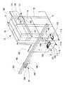
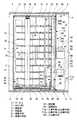
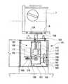
図1〜図3において、荷保管設備10は、矩形箱状の囲壁体11と、この囲壁体11内に配設された回転棚21、移載手段51、固定棚101、ならびに囲壁体11を貫通して配設された入出庫手段111a,111bなどにより構成されている。
【0013】
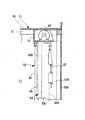
前記囲壁体11は、枠組体12と、この枠組体12の外側で下半分に取り付けられた下部外板13と、枠組体12の外側で上半分に取り付けられた上部外板14と、枠組体12の下側に取り付けられた床板15と、枠組体12の上側に取り付けられた天井板16などにより密閉状に構成されている。その際に、下部外板13や上部外板14の少なくとも一部、主として上部外板14には樹脂製などの透明板が使用され、以て、囲壁体11内の荷保管室(荷保管空間)17の状況を、透明板を透して外から把握し得るように構成されている。なお囲壁体11は、前記床板15の下面側に設けられた脚体19を介して床2上に配設されている。
【0014】
図1、図3〜図5において、前記荷保管室17内の一側寄りの位置には前記回転棚21が配設されている。この回転棚21は、縦方向の回転棚軸心22の周りで回転自在に設けられるとともに、前記回転棚軸心22を中心とした回転円経路23上に複数の荷受け部32が設けられている。
【0015】
すなわち底板15上には、前記回転棚軸心22を中心とした円状のLMガイド手段25を介して円板状の回転体26が設けられている。この回転体26の中央部分からは、前記回転棚軸心22上に位置される状態で6角筒状の縦軸体27が立設され、この縦軸体27の上端には閉塞板27Aが設けられている。そして閉塞板27Aの中央部分から立設された縦ピン28が、前記囲壁体11の上部に設けられた支持プレート20に対して、軸受装置29を介して遊転自在に支持されている。
【0016】
前記縦軸体27の上下方向の複数箇所には、6角状の環状板30が外嵌して配設され、これら環状板30は複数の取付け部材31などを介して縦軸体27に連結されている。各環状板30の周方向の6箇所(複数箇所)に前記荷受け部32が配設され、これら荷受け部32は板枠状であって、その基端が連結具33を介して環状板30側に連結されることで、横外方へ突出される状態で環状板30側に片持ち状で支持されている。
【0017】
そして荷受け部32には、上下ならびに遊端(外側)に開放される凹所34が形成されるとともに、この凹所34の周辺の3箇所(単数個所または複数箇所)からは位置決めピン35が立設されている。また、荷受け部32の基端部分には在荷検出手段の一部を構成する反射ミラー36が、遊端部分にはレベル検出手段の一部を構成する反射テープ37がそれぞれ設けられている。
【0018】
前記回転棚21を回転させる回転棚駆動手段41が設けられている。すなわち、前記底板15の隅部には回転駆動部42が設けられ、この回転駆動部42からの下向きの駆動軸43には駆動ギヤ44が設けられている。そして前記回転体26の周縁にはリングギヤ45が設けられ、このリングギヤ45に前記駆動ギヤ44が常時噛合されている。ここで回転駆動部42は、モータや減速機などからなり、前記駆動軸43を正逆に駆動すべく構成されている。
【0019】
したがって、回転棚駆動手段41の回転駆動部42により駆動軸43を正逆に駆動させることで、駆動ギヤ44やリングギヤ45などを介して回転棚21を、回転棚軸心22の周りで正逆に回転し得る。その際に回転棚21は、最大で180°の回転が行われるように構成されている。以上の22〜45などにより回転棚21の一例が構成される。
【0020】
図1、図3、図6〜図8において、前記荷保管室17内の他側寄りの位置には前記移載手段51が配設されている。この移載手段51の移載作用部81は、前記回転棚軸心22に平行状の移載軸心52の周りで回転自在に設けられるとともに、前記回転円経路23に接線状に重合される移載円経路53上で作用自在に構成されている。
【0021】
すなわち、底板15上にはベース枠54が設けられ、このベース枠54からポスト体55が立設されるとともに、このポスト体55の前面側にはガイドレール56が設けられている。ここでポスト体55は、左右一対の側部材55Aと、これら側部材55Aの内側面間に設けられた後部材55Bと、この後部材55Bの前面側に設けられた前部材55Cとからなり、これら前部材55Cの前面側に、前記ガイドレール56がそれぞれ設けられている。そしてポスト体55の上端には上枠57が設けられ、また前部材55Cにはそれぞれカバー体58が設けられている。
【0022】
前記ガイドレール56に被ガイド体59を介して昇降自在(LMガイド)に案内される昇降部60が設けられるとともに、この昇降部60に連動された昇降駆動手段61が設けられている。すなわち昇降部60は、前記被ガイド体59側に連結された縦方向部材60Aと、この縦方向部材60Aの下端から前方へと連設された横方向部材60Bとにより、側面視でL字状に形成されている。
【0023】
前記昇降駆動手段61は、前記ベース枠54内に配設された駆動輪体62と、前記上枠57の部分に配設された従動輪体63と、両輪体62,63間に巻回される回動体(タイミングベルトなど)64と、前記駆動輪体62の近くに配設された案内輪体65と、前記駆動輪体62に連動された回転駆動部66などにより構成されている。ここで各輪体62,63,65は左右一対であり、そして回動体64も左右一対に配設されている。
【0024】
その際に各回動体64は、駆動輪体62に巻回される下位回動部64Aと、従動輪体63に巻回される上位回動部64Bとからなる。そして、ポスト体55の前面側に位置されるそれぞれの遊端は前記被ガイド体59側に連結され、また後面側に位置されるそれぞれの遊端間は張力調整具67を介して連結されている。前記回転駆動部66は、正逆駆動可能なモータや減速機などから構成され、その駆動軸68に一対の駆動輪体62が取り付けられている。
【0025】
前記昇降部60の横方向部材60B上には、前記移載軸心52の周りで回転自在な回転体70が設けられ、その際に回転体70の中央部分から垂設された縦軸71が横方向部材60B側の軸受72に回転自在に支持されている。そして前記縦軸71に連動された回転駆動手段73が設けられている。
【0026】
すなわち回転駆動手段73は、前記縦方向部材60Aから横方向部材60Bに亘って設けられた回転駆動部74と、その下向きの駆動軸75に取り付けられた駆動輪体76と、前記縦軸71に取り付けられた従動輪体77と、両輪体76,77間に巻回された無端回動体(タイミングベルトなど)78と、前記横方向部材60B内に配設された複数の案内輪体79などにより構成されている。ここで前記回転駆動部74は、正逆駆動可能なモータや減速機などから構成されている。
【0027】
前記移載作用部81はフォーク形式であって、前記回転体70に対して前後方向(横方向)に出退自在に配設され、以て前記移載軸心52の周りで回転自在に設けられる。すなわち移載作用部81は、前後方向の支持板81Aと、この支持板81Aの中間部分から立設されたずれ規制板81Bなどにより構成されている。そして、前記ずれ規制板81Bよりも前方において、支持板81A上の複数箇所からは位置決めピン82が立設されている。
【0028】
前記回転体70上には、左右一対のレール材83が前後方向に配設されるとともに、これらレール材83間でかつ左右方向の中央部分には前後方向のガイド体84が設けられている。そして、前記支持板81Aの後端で下面側には、前記ガイド体84に外嵌されてLMガイドを構成する被ガイド体85が設けられている。
【0029】
前記移載作用部81を前後方向に出退させる出退駆動手段90が設けられている。すなわち出退駆動手段90は、ガイド体84に沿って配設された螺子軸91と、前記移載作用部81の下面側に設けられかつ前記螺子軸91に螺合されるナット体92と、前記回転体70上に搭載されかつ前記螺子軸91にベルト連動機構93を介して連動された回転駆動部94などにより構成されている。ここで回転駆動部94は、正逆駆動可能なモータや減速機などから構成されている。
【0030】
なお前記移載作用部81の支持板81Aは、前記荷受け部32の凹所34に対して昇降自在に構成されている。そして前記ポスト体55の部分には、被ガイド体59側の昇降を許しかつ両カバー体58間の隙間を閉塞可能な防塵ベルト87が設けられ、また回転体70の部分には、移載作用部81の前後動を許しかつガイド体84の上方を閉塞可能な防塵ベルト88が設けられている。
【0031】
以上の52〜94などにより移載手段51の一例が構成される。そして移載手段51の移載作用部81は、前記回転棚軸心22に平行状の移載軸心52の周りで回転自在に設けられるとともに、前記回転円経路23に接線状に重合される移載円経路53上で作用自在に構成されることになる。
【0032】
図1、図3、図9、図10において、前記固定棚101は、前記荷保管室17内の他側寄りの位置でかつ前記移載円経路53上の4箇所(単数箇所または複数箇所)に設けられている。すなわち囲壁体11内において、枠組体12側の上下方向の複数箇所には横方向のフラットバー102が連結され、そして各フラットバー102には荷支持部103が設けられている。これら荷支持部103は板枠状であって、その基端が連結具104を介してフラットバー102側に連結され、以て横前方へ突出される状態でフラットバー102側に片持ち状で支持されている。
【0033】
そして荷支持部103には、上下ならびに遊端(外側)に開放される凹所105が形成されるとともに、この凹所105の周辺の3箇所(単数個所または複数箇所)からは位置決めピン106が立設されている。なお、前記凹所105に対して前記移載作用部81の支持板81Aが昇降自在に構成されている。以上の102〜106などにより固定棚101の一例が構成される。
【0034】
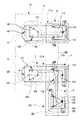
図1〜図3、図10〜図14において、前記移載円経路53上の4箇所に設けられた固定棚101のうちで、前記回転棚21とは離れた側の2箇所(単数箇所または複数箇所)の固定棚101の下部には、下から3段分(下から複数段分)の荷支持部103を削除して空間部分107が形成されている。そして、これら空間部分107を利用して、前記移載手段51との間で荷を受け渡し自在な入出庫手段が設けられている。その際に入出庫手段の入出庫方向は、回転棚軸心22と移載軸心52とを結んだ線109に対して平行状に設定されている。
【0035】
すなわち、囲壁体11における他側の下部外板13には、両空間部分107に対向されてそれぞれ入庫用貫通部110aと出庫用貫通部110bが形成され、これら貫通部110a,110bを通して囲壁体11の内外に亘る状態で、入庫手段(入出庫手段)111aと出庫手段(入出庫手段)111bとが設けられている。
【0036】
ここで入庫手段111aと出庫手段111bは同様な構成であって、囲壁体11の内外に亘る箱枠状の本体112を有し、この本体112上の外端部分には一時受け体113が設けられている。この一時受け体113は一枚板状または分割板状であって、凹所や貫通などによって昇降作用部114が形成されるとともに、この昇降作用部114の周辺の3箇所(単数個所または複数箇所)からは位置決めピン115が立設されている。
【0037】
前記本体112内には、ガイド体116に支持案内されて内外方向(前後方向)に移動自在な移動部材117と、この移動部材117を内外方向に移動させる移動装置118とが設けられている。
【0038】
ここで移動装置118は、移動部材117側に設けられた駆動部(モータなど)119と、この駆動部119からの左右方向の出力軸120に取り付けられたタイミングプーリ121と、このタイミングプーリ121の上方で内外方向の2箇所において移動部材117側に遊転自在に設けられたガイドプーリ122と、これらタイミングプーリ121からガイドプーリ122に亘って掛けられたタイミングベルト123などによって構成されている。なおタイミングベルト123の両端は、前記本体112側の内外端部に固定124されている。
【0039】
前記移動部材117には昇降装置125が設けられている。この昇降装置125は、移動部材117側に軸受126を介して回転自在に設けられた縦方向の螺子軸体127と、移動部材117側に設けられた正逆駆動自在な駆動部(モータなど)128と、この駆動部128からの下向きの出力軸129と前記螺子軸体127との間に設けられた無端連動機構130と、前記螺子軸体127に螺合されたナット体131と、このナット体131を昇降案内すべく移動部材117側との間に設けられたガイド機構132などにより構成されている。そしてナット体131側に昇降部材133が連結されている。
【0040】
これら昇降部材133には旋回装置135が設けられている。この旋回装置135は、昇降部材133側に連結されたブラケット136と、このブラケット136側に軸受137を介して回転自在に設けられた縦方向の軸体138と、ブラケット136側に設けられた正逆駆動自在な駆動部(モータなど)139と、この駆動部139からの上向きの出力軸140と前記軸体138との間に設けられた無端連動機構141などにより構成されている。そして軸体138の上端に昇降体142が連結されている。ここで昇降体142は板状であり、前記一時受け体113の昇降作用部114に対して嵌合自在に構成されている。
【0041】
なお、本体112上の内端部分で、所定の3箇所(単数個所または複数箇所)からは位置決めピン143が立設されている。前記本体112などは、貫通部110a,110bに対して直角状で通り、以て入庫手段111aと出庫手段111bの入出庫方向145は、回転棚軸心22と移載軸心52とを結んだ線109に対して平行状に設定されている。以上の112〜145などにより入庫手段111aや出庫手段111bの一例が構成される。
【0042】
前記出庫手段111bにおける外端部の側方にはストレージ手段151が一体状に設けられている。すなわち、前記本体112に一体状とした箱枠状の本体152が、この本体112とによって平面視でL字状として配設されている。前記本体152上の遊端部分(出庫手段111bとは離れた側)には一時受け体153が設けられている。この一時受け体153は一枚板状であって、凹所によって昇降作用部154が形成されるとともに、この昇降作用部154の周辺の3箇所(単数個所または複数箇所)からは位置決めピン155が立設されている。
【0043】
前記本体152内には、ガイド体156に支持案内されて左右方向に移動自在な移動部材157と、この移動部材157を内外方向に移動させる移動装置158とが設けられている。ここで移動装置158は前記移動装置118と同様であって、駆動部159、出力軸160、タイミングプーリ161、ガイドプーリ162、タイミングベルト163などによって構成されている。そしてタイミングベルト163の両端は、前記本体152側の端部に固定164されている。
【0044】
前記移動部材157には昇降装置165が設けられている。この昇降装置165は前記昇降装置125と同様であって、軸受166、螺子軸体167、駆動部168、出力軸169、無端連動機構170、ナット体171、ガイド機構172などにより構成されている。そしてナット体171側に、昇降部材173を介して昇降体174が連結されている。ここで昇降体174は板状であり、前記一時受け体113,153の昇降作用部114,154に対して嵌合自在に構成されている。以上の152〜174などによりストレージ手段151の一例が構成される。
【0045】
上述したように、囲壁体11内には回転棚21と移載手段51と固定棚101とが設けられ、これら回転棚21と移載手段51と固定棚101とは、回転円経路23と移載円経路53との両方とも単数として配設されている。そして固定棚101は、前記移載円経路53上の4箇所(複数箇所)に設けられている。
【0046】
また、回転棚21には荷受け部32群が上下複数段に設けられ、固定棚101には荷支持部103が上下複数段に設けられている。さらに移載手段51は、回転棚21や固定棚101の上下複数段に対応して作用可能に構成されている。なおカセット(荷の一例)7の下面側には、前記位置決めピン35,82,106,115,143,155群の嵌合を許す嵌合部8が、凹入長孔状に形成されている。ここでカセット7は、被処理物(図示せず。)を収納可能に構成されている。
【0047】
前記荷保管設備10は、その入庫手段111aと出庫手段111bとの外端部分が、囲壁体11における下部外板(外板)13の外方部分に位置され、以て囲壁体11外のクリーンルーム5内に作用自在に構成されている。すなわち、外板13,14の前板部分などに連設されて隔壁体180が設けられている。そして隔壁体180などにより囲まれた箇所がクリーンルーム5に形成されている。これにより荷保管設備10は、その外板13,14、が隔壁体150の一部に兼用されるとともに、下部外板13に形成された荷入出部148がクリーンルーム5に臨んで設けられることになる。
【0048】
前記クリーンルーム5は、たとえば天井1側にフィルター3が設けられ、そして床2側に吸引用のグレーチング床(多孔板)4が設けられて構成されており、以てフィルター3を通してクリーンエアAが噴出され、このクリーンエアAがグレーチング床4を通して吸引されるダウンフロー方式とされている。これによりクリーンルーム5内はクリーン雰囲気とされている。
【0049】
前記クリーンルーム5内には、荷保管設備10との間でのカセット7の受け渡しを行う荷搬送手段181が設けられ、以てカセット7の受け渡しが、クリーンルーム5内で行われるように構成されている。前記荷搬送手段181は、天井側のレール装置182と、このレール装置182に支持案内され自動走行自在な吊り走行形式の移動体183と、この移動体183の下部側に設けられた荷保持部184などにより構成されている。そして荷保持部184には、荷吊り装置185が昇降動自在に設けられている。ここで、荷搬送手段181による搬送経路186は、荷入出部148の上方を通るように形成されている。
【0050】
図1〜図3において、前記荷保管設備10における上部外板14の外側を通る上部搬送手段191が設けられている。すなわち上部搬送手段191は、天井側のレール装置192と、このレール装置192に支持案内され自動走行自在な移動体193と、この移動体193の上部側に設けられた荷支持部194などにより構成されている。ここで荷支持部194は、たとえばフォーク形式などからなる。
【0051】
前記囲壁体11の上部外板14には、上部搬送手段191との間でカセット7の受け渡しを行うための荷通過部195が形成されている。すなわち、回転棚21に近い側において、上部外板14には荷通過部195が開口により形成されている。そして、荷通過部195を通して移動体193の荷支持部194がフォーク動されることで、目的とする荷受け部32との間でカセット7を受け渡し自在に構成されている。
【0052】
なお、荷通過部195の部分に、前記移動体193の荷支持部194との間でカセット7を受け渡し自在な、たとえばフォーク形式などからなる受け渡し手段が設けられた形式などであってもよい。さらには上部搬送手段191などが省略された形式などであってもよい。
【0053】
以下に、上記した第1の実施の形態における作用を説明する。
クリーンルーム5では、天井1側のフィルター3を通して噴出させたクリーンエアAをグレーチング床4の下側に排出させることで、ダウンフロー方式によりクリーン雰囲気を保っている。このようなクリーンルーム5を利用して、カセット7を荷保管装置10に入庫して保管するに、まず入庫しようとするカセット7を入庫手段111aの始端部分(外端部分)に載置させる。
【0054】
すなわち、荷搬送手段131の作動などによって、図11のEに示すように、入庫手段111aにおける一時受け体113上に、入庫しようとするカセット7を載置させ、位置決めピン115に嵌合部8を嵌合させる。この前後に、下降しかつ正姿勢の昇降体142を昇降作用部114の下方に位置させている。
【0055】
この状態で、まず昇降装置125の駆動部128を作動させ、無端連動機構130などを介して螺子軸体127を回転させる。すると、螺子軸体127の回転に伴ってナット体131が上昇し、昇降部材133を介して旋回装置135を上昇させ、以て旋回装置135側の軸体138に連結している昇降体142を上昇させる。この上昇する昇降体142は昇降作用部114を通り、図12の仮想線に示すように、一時受け体113上のカセット7を持ち上げる。
【0056】
次いで移動装置118の駆動部119を作動させ、タイミングベルト123が掛けられているタイミングプーリ121を駆動回転させることで、移動部材117をガイド体116に支持案内させながら入庫手段111aの終端部分(内端部分)に向け移動させる。このとき、昇降装置125や旋回装置135を介して昇降体142も移動し、以てカセット7を、入庫用貫通部110aを通して囲壁体11内に搬送したのち、図11のFや図12の実線に示すように、終端部分で停止し得る。これによりカセット7を、図9に示すように、固定棚101の下部に形成した空間部分107などに位置し得る。
【0057】
そして、旋回装置135の駆動部139を作動させ、無端連動機構141などを介して軸体138を回転させ、以て図11のGや図12の実線に示すように、昇降体142を介してカセット7の向きを傾斜方向に変更させる。すなわちカセット7を、固定棚101の荷支持部103により支持し得る向きに変更させる。
【0058】
次いで、昇降装置125の駆動部128を逆作動させ、無端連動機構130などを介して螺子軸体127を逆回転させる。すると、螺子軸体127の逆回転に伴ってナット体131が下降し、昇降部材133を介して旋回装置135を下降させることになって、旋回装置135側の軸体138に連結している昇降体142を下降させる。この下降する昇降体142は位置決めピン143間を通り、以てカセット7を、その嵌合部8を位置決めピン143に嵌合させた状態で本体112側に載置させる。
【0059】
そして旋回装置135の駆動部139を逆作動させ、無端連動機構141などを介して軸体138を逆回転させ、以て昇降体142の向きを正姿勢に変更させる。次いで移動装置118の駆動部119を逆作動させ、タイミングベルト123が掛けられているタイミングプーリ121を逆に駆動回転させることで、移動部材117を入庫手段111aの始端部分(外端部分)に向け移動させる。このとき、昇降装置125や旋回装置135を介して昇降体142も移動し、以て下降しかつ正姿勢の昇降体142を昇降作用部114の下方に位置させ、最初の状態に戻し得る。
【0060】
次いで、入庫手段111aの内端部分に位置させたカセット7を、移載手段51により受け取る。その際に図6の実線に示すように、空の移載作用部81を回転体70内に退入動させた状態で、この移載作用部81の回転と昇降とを、同時状にまたはいずれかを先行して相前後して行う。
【0061】
すなわち移載作用部81を回転させるに、回転駆動手段73における回転駆動部74を正逆に駆動させ、駆動軸75を介して駆動輪体76を正逆に回転させる。これにより、無端回動体78や従動輪体77を介して縦軸71を正逆に回転させ得、以て回転体70を介して移載作用部81を、移載軸心52の周りに正逆に回転させ得る。
【0062】
また移載作用部81を昇降させるに、昇降駆動手段61における回転駆動部66を正逆に駆動させ、駆動軸68を介して駆動輪体62を正逆に回転させる。これにより、回動体64を正逆に回動させ得、以て被ガイド体59や昇降部60を介して移載作用部81を昇降し得る。このようにして移載作用部81を回転ならびに昇降させることで、この移載作用部81を、入庫手段111aの内端部分に対して、少し下方のレベルで対抗し得る。
【0063】
次いで、移載作用部81を突出動させる。すなわち、出退駆動手段90における回転駆動部94を駆動させ、ベルト連動機構93を介して螺子軸91を回転させる。これにより、ナット体92が螺合移動することになって移載作用部81を突出動させ得、その際に移載作用部81は、ガイド体84により被ガイド体85を案内することで、図6の仮想線で示すように直線状に突出動し得る。この突出動によって移載作用部81を、入庫手段111aの内端部分に載置させたカセット7の下方に位置し得る。
【0064】
この状態で、前述したような昇降駆動手段61の動作により、昇降部60などを介して移載作用部81を少し上昇させる。すると、移載作用部81が入庫手段111aにおける本体112の内端部分を上昇し、以て入庫手段111aの内端部分に位置させたカセット7を持ち上げ得、その際に位置決めピン82を嵌合部8に嵌合させる。そして出退駆動手段90を前述とは逆作動させて、移載作用部81を退入動させることにより、カセット7を回転体70の上方に位置し得る。
【0065】
次いで、前述と同様に移載作用部81を回転させるとともに、必要に応じて昇降させることで、カセット7を目的とする固定棚101の目的とする荷支持部103に対抗し得る。このとき移載作用部81は、荷支持部103よりも少し上方に位置している。
【0066】
そして、前述と同様にして移載作用部81を突出動させることで、カセット7を荷支持部103の上方に位置し得、次いで移載作用部81を少し下降動させることで、カセット7を荷支持部103上に載置し得る。その際に嵌合部8を位置決めピン106に嵌合させ、その後に移載作用部81を退入動させる。これにより、入庫手段111aの内端部分に位置させていたカセツト7を固定棚101に対して入庫し得る。すなわち、入庫手段111aに供給したカセット7を、移載円経路53上に設けられた固定棚101の荷支持部103に入庫させる入庫作業を終了する。
【0067】
また、入庫手段111aの内端部分に位置させたカセット7は、回転棚21にも入庫し得る。すなわち、前述したように入庫手段111aの内端部分に位置させたカセット7を、移載手段51により受け取る作業中に、回転棚21を先行して回転し準備させる。
【0068】
この回転棚21の回転は、回転棚駆動手段41における回転駆動部42を正逆に駆動させ、駆動軸43を介して駆動ギヤ44を正逆に回転させる。これにより、リングギヤ45を正逆に回動させ得、以て縦軸体27などを介して荷受け部32群を回転棚軸心22の周りに回転し得る。その際に、荷受け部32群は回転円経路23上で回転移動し、そして、目的とする荷受け部32が移載円経路53に接線状に重合した位置に達したときに、その回転を停止させる。
【0069】
なお回転棚21の回転は、前述した重合位置に対して目的とする荷受け部32の回転距離が短い方に、最大で180°に正または逆に行われ、以て迅速にかつ能率的に回転し得る。また、移載手段51により受け取る作業中に、回転棚21を先行して回転し準備させることで、全体の稼動能率を向上し得る。なお、目的とする荷受け部32が最初から重合位置にあるときには、回転棚21の回転は行われない。
【0070】
このように、目的とする荷受け部32を重合位置に停止させたのち、前述と同様に移載手段51を作用させることで、移載作用部81で支持していたカセット7を、図1、図5で示すように荷受け部32上に載置し得る。その際に嵌合部8を位置決めピン35に嵌合させる。これにより、入庫手段111aの内端部分に位置させていたカセット7を、回転棚21の目的とする荷受け部32上に載置し得、以て入庫手段111aに供給したカセット7の回転棚21に対する入庫作業を終了する。
【0071】
なお、固定棚101に保管しているカセット7も、移載手段51の作動や回転棚21の回転により、同様にして回転棚21に移して保管し得る。その際に、固定棚101のカセット7を移載手段51により受け取る作業中に、回転棚21を先行して回転し準備させることで、全体の稼動能率を向上し得る。なお、目的とする荷受け部32が最初から重合位置にあるときには、回転棚21の回転は行われない。
【0072】
前記移載手段51を上述とは逆に動作させることによって、カセット7の出庫作業を行える。すなわち、回転棚21の目的とする荷受け部32上に載置してあるカセット7を、出庫手段111bの始端部分(内端部分)に位置させ得、また目的とする固定棚101の目的とする荷支持部103に上に載置してあるカセット7を出庫手段111bの始端部分に位置させ得る。
【0073】
つまり、まず移載手段51の作動によって、図11のHで示すように、出庫手段111bにおける本体112の始端部分に、その嵌合部8を位置決めピン143に嵌合させた状態で載置させる。次いで出庫手段111bを、前述した入庫手段111aとはほぼ逆に作動させる。すなわち、傾斜方向に向き変更させている昇降体142を上昇させてカセット7の持ち上げを行う。
【0074】
そして図11のIで示すように、昇降体142の向きを正姿勢に変更させたのち、移動部材117をガイド体116に支持案内させながら出庫手段111bの終端部分(外端部分)に向け移動させる。このとき、昇降装置125や旋回装置135を介して昇降体142も移動し、以てカセット7を、出庫用貫通部110bを通して囲壁体11外に搬送させたのち、図11のJで示すように、出庫手段111bの終端部分で停止させる。
【0075】
次いで昇降体142を、一時受け体113の昇降作用部114を通して下降させ、以てカセット7を、その嵌合部8を位置決めピン115に嵌合させた状態で一時受け体113側に載置させる。このようにカセット7を、出庫手段111bの終端部分(外端部分)に位置させることで、出庫作業を終了する。
【0076】
なお、回転棚21に保管しているカセット7も、移載手段51の作動や回転棚21の回転などにより、同様にして固定棚101に移して(出庫して)保管し得る。
【0077】
上述したようにして出庫手段111bの終端部分に出庫したカセット7は、ストレージ手段151によってストレージし得る。すなわち、移動部材157を出庫手段111b側に移動させて、下降させている昇降体174を一時受け体113における昇降作用部114の下方に位置させる。そして昇降体174を上昇させて、図13の仮想線で示すようにカセット7を持ち上げたのち、移動部材157を遊端部分側に移動させ、以て図13の実線や図14で示すように、カセット7を一時受け体153の上方に位置させる。
【0078】
次いで昇降体174を、一時受け体153の昇降作用部154を通して下降させ、以てカセット7を、その嵌合部8を位置決めピン155に嵌合させた状態で一時受け体153側に載置させる。このようにカセット7を、ストレージ手段151の遊端部分に位置させることで、図11のKで示すようにストレージし得る。
【0079】
上述したような各動作において、カセット7の嵌合部8が位置決めピン35,82,106,115,143,155に嵌合することで、回転中の遠心力などによってカセット7が互いに衝突したり、カセツト7が位置ずれしたり脱落することを防止し得る。
【0080】
上述したように移載手段51は、移載作用部81を移載軸心52の周りに回転させるだけで走行移動などは行わないことから、走行移動などのための占有スペースは不要となり、回転棚21と固定棚101とを含めた全体をコンパクトに構成し得る。
【0081】
しかも、回転棚21と固定棚101とにより保管量を増加し得るとともに、走行構成のない移載手段51は移載作用部81を床近くまで下降し得ることで、それに合わせて、回転棚21の荷受け部32による保管レベルと固定棚101の荷支持部103による保管レベルとを床近くまで下げ得、以て保管量をより増加し得る。したがって、クリーンルームのようなクリーン空間をできるだけ狭くしたい場所に容易にかつ好適に採用し得る。
【0082】
前述したように、出庫手段111bの終端部分に位置させることで、クリーンルーム5内の荷入出部148に出庫したカセット7、ならびにストレージ手段151でストレージしたカセット7は、荷搬送手段181により目的とする場所に搬送し得る。すなわち、荷搬送手段181の移動体183を搬送経路186上で移動させ、出庫手段111bの終端部分やストレージ手段151に位置しているカセット7の上方で停止させる。
【0083】
次いで荷吊り装置185を下降動させてカセット7のクランプを行ったのち、荷吊り装置185を上昇動させてカセット7の持ち上げを行い、そして持ち上げたカセット7を荷保持部184によって保持する。この状態で、移動体183を搬送経路186上で移動させることで、目的とする場所へと搬送し得る。
【0084】
また、カセット7を前述したようにして移動体183側で支持したのち、搬送経路186上で搬送させる。この後にカセット7は、上述したように入庫手段111aにおける一時受け体113上に載置させることで、荷保管設備10に入庫し得る。
【0085】
なお、クリーンルーム5においては、クリーンエアAがダウンフロー方式により流れていることで、荷入出部148や荷搬送手段181などで発生した塵埃を、その流れに乗せて迅速に除去し得る。したがってクリーンルーム5においては、充分なクリーン雰囲気(クリーン度)でカセット7の搬送などを行える。
【0086】
次に、本発明の第2〜第6の実施の形態を、図15、図16に基づいて説明する。
すなわち、図15の(a)は第2の実施の形態を示し、回転棚21と移載手段51と固定棚101とは、回転円経路23が2つ(複数)で移載円経路53が1つ(単数)として配設されている。そして、両回転棚21の回転棚軸心22と移載手段51の移載軸心52が同じ線109上に位置されている。さらに入庫手段111aと出庫手段111bとは回転棚21の下部に形成された空間部分に位置されている。
【0087】
また、図15の(b)は第3の実施の形態を示し、上述した第2の実施の形態の変形例で、一方の回転棚21の回転棚軸心22は、他方の回転棚21の回転棚軸心22と移載手段51の移載軸心52とを結ぶ線109から外れている。
【0088】
そして、図15の(c)は第4の実施の形態を示し、回転棚21と移載手段51と固定棚101とは、回転円経路23が3つ(複数)で移載円経路53が1つ(単数)として配設されている。
【0089】
さらに、図16の(a)は第5の実施の形態を示し、回転棚21と移載手段51と固定棚101とは、回転円経路23が1つ(単数)で移載円経路53が2つ(複数)として配設されている。
【0090】
また、図16の(b)は第6の実施の形態を示し、回転棚21と移載手段51と固定棚101とは、回転円経路23と移載円経路53との両方とも2つ(複数)として配設されている。
【0091】
上記した実施の形態では、移載手段51として、回転体70を移載軸心52の周りに回転自在とした形式が示されているが、これは移載作用部81も含めて移載手段51の全体を、たとえばポスト体55の部分に位置される移載軸心の周りに回転自在とした形式などであってもよい。
【0092】
上記した実施の形態では、移載手段51として、その移載作用部81をカセット7の底面に作用させる形式が示されているが、これはカセット7の側部や上部から側方に突出させた被係止部に下方から係止させる形式などであってもよい。
【0093】
上記した実施の形態では、移載円経路53上の複数箇所に固定棚101が設けられているが、これは単数箇所に固定棚101が設けられた形式であってもよい。
【0094】
上記した実施の形態では、回転棚21は正逆に回転自在であり、最大で180°の回転が行われるように構成されているが、これは正逆の回転が180°以上で行われる形式や、回転が一方向のみに行われる形式などであってもよい。
【0095】
上記した実施の形態では、固定棚101に対する移載手段51の作業中に、回転棚21が先行して準備されるように構成されているが、これは固定棚101に対する移載手段51の作業が終了した後に、回転棚21が準備される形式などであってもよい。
【0096】
上記した実施の形態では、回転棚21から最も離れた2個の固定棚101に対応して、入庫手段111aと出庫手段111bとが設けられているが、これは回転棚21に接近した固定棚101と最も離れた2個の固定棚101とに対応して、入庫手段111aと出庫手段111bとが設けられた形式であってもよい。この場合には、両側に振り分けて2組の入庫手段111aと出庫手段111bとを設けることもできる。
【0098】
上記した実施の形態では、出庫手段111bに連続される状態でストレージ手段151が配設された形式が示されているが、これは入庫手段111a側にもストレージ手段が配設された形式、ストレージ手段151が省略された形式などであってもよい。
【0099】
上記した実施の形態では、入庫手段111aと出庫手段111bとの入出庫方向145が、回転棚軸心22と移載軸心52とを結んだ線109に対して平行状に設定されており、これによると、入庫手段111aや出庫手段111bを囲壁体11内に、無駄なスペースが生じることなく配設し得、以て荷保管設備をコンパクトに構成し得る。しかし入庫手段111aと出庫手段111bとは、その入出庫方向145を任意な方向として配設された形式などであってもよい。
【0100】
上記した実施の形態では、回転棚21と移載手段51と固定棚101とは囲壁体11内に配設され、入庫手段111aと出庫手段111bとは、囲壁体11外のクリーンルーム5内に作用自在に構成されており、これによると、入庫手段111aや出庫手段111bを作動させることで、クリーンルーム5内の荷入出部148と移載手段51による荷受け渡し位置との間でカセット7を入出庫でき、したがってクリーンルーム5などに容易に採用できる。しかし、荷保管設備10に対してクリーンエアAを供給して、回転棚や固定棚において、充分なクリーン雰囲気で荷の保管を行うようにした形式であってもよい。
【0101】
上記した実施の形態では、空間部分107が、回転棚21や固定棚101における下から複数段分の荷受け部32や荷支持部103を削除して形成されており、これによると、入庫手段111aや出庫手段111bを嵩低くしてコンパクトに構成できる。
【0102】
上記した実施の形態では、荷保管設備10の外板13,14が隔壁体180に兼用されることでクリーンルーム5が形成されており、これによると隔壁体180の材料使用量を減少できて安価に構成できるとともに、相互に補強し合う構成にできる。しかし、これは隔壁体180のみによってクリーンルーム5が形成された構成であってもよく、この場合に隔壁体180には、荷入出部148用の開口部が形成される。
【0103】
上記した実施の形態では、荷保管設備10に対してカセット7の受け渡しを行うために、天井側で自動走行形式の荷搬送手段181が設けられているが、荷搬送手段としては、床側で自動走行可能な台車形式や、床側で手押し走行可能な台車形式などであってもよい。さらに、荷搬送手段を省略して、クリーンルーム5内において人手操作によりカセット7の受け渡しを行ってもよい。
【0104】
上記した実施の形態では、荷としてカセット7が示されているが、これは他の物品でもよく、またパレットを取り扱う形式などであってもよい。
【0105】
【発明の効果】
上記した本発明の請求項1によると、回転棚を回転棚軸心の周りに回転させて、回転円経路と移載円経路との重合部分に目的とする荷受け部を位置させることで、この荷受け部に対して、移載手段により荷の出し入れを行うことができる。また、移載手段の移載作用部を移載手段軸心の周りに回転させることで、固定棚に対して、移載手段により荷の出し入れを行うことができる。
【0106】
このように移載手段は、移載作用部を回転させるだけで走行移動などは行わないことから、走行移動などのための占有スペースを不要にできて、回転棚と固定棚とを含めた全体をコンパクトに構成できる。しかも、回転棚と固定棚とにより保管量を増加できるとともに、走行構成のない移載手段は移載作用部を床近くまで下降できることで、それに合わせて回転棚と固定棚の保管レベルを下げることができて、保管量をより増加できることになる。したがって、クリーンルームのようなクリーン空間をできるだけ狭くしたい場所に容易にかつ好適に採用できる。
【0107】
しかも、回転棚の荷受け部群や固定棚の荷支持部群によって、上下高さを最大限に利用して保管量を増加し得るものでありながら、荷受け部や荷支持部を削除して形成した空間部分を利用して配設した入出庫手段によって、外部に対する荷の出し入れは、保管量をさほど減少させることなく常に円滑に行うことができる。その際に入出庫手段を嵩低くしてコンパクトに構成できる。
さらに荷の入庫は、まず荷を入出庫手段の外端部分における一時受け体上に載置させ、そして昇降体の上昇動により一時受け体上の荷を持ち上げ、次いで昇降体を内端部分に向け移動させて、荷を、貫通部を通して囲壁体内に搬送したのち内端部分で停止させることにより、荷を空間部分に位置でき、以て移載手段の作動によって入庫できる。また荷の出庫は、まず移載手段の作動によって、入出庫手段における本体の内端部分に荷を載置させ、そして昇降体を上昇させて荷の持ち上げを行い、次いで昇降体を外端部分に向け移動させて、荷を、貫通部を通して囲壁体外に搬送したのち外端部分で停止させ、そして昇降体を下降させて、荷を一時受け体側に載置させることにより、行うことができる。
【0108】
また上記した本発明の請求項2によると、入出庫手段を囲壁体内に、無駄なスペースが生じることなく配設でき、以て荷保管設備をコンパクトに構成できる。そして上記した本発明の請求項3によると、入出庫手段を作動させることで、クリーンルーム内と移載手段による荷受け渡し位置との間で荷を入出庫でき、したがってクリーンルームなどに容易に採用できる。
【図面の簡単な説明】
【図1】本発明の第1の実施の形態を示し、荷保管設備の横断平面図である。
【図2】同荷保管設備の外観斜視図である。
【図3】同荷保管設備の縦断側面図である。
【図4】同荷保管設備における回転棚の下部の一部切り欠き側面図である。
【図5】同荷保管設備における回転棚の上部の一部切り欠き側面図である。
【図6】同荷保管設備における移載手段の下部の一部切り欠き側面図である。
【図7】同荷保管設備における移載手段の上部の一部切り欠き側面図である。
【図8】同荷保管設備における移載手段の一部切り欠き平面図である。
【図9】同荷保管設備における固定棚の側面図である。
【図10】同荷保管設備における固定棚の平面図である。
【図11】同荷保管設備における入出庫手段部分の概略平面図である。
【図12】同荷保管設備における入庫手段部分の一部切り欠き側面図である。
【図13】同荷保管設備における出庫手段からストレージ手段部分の一部切り欠き正面図である。
【図14】同荷保管設備におけるストレージ手段部分の一部切り欠き側面図である。
【図15】本発明の第2〜第4の実施の形態を示し、(a)は第2の実施の形態を示す概略平面図、(b)は第3の実施の形態を示す概略平面図、(c)は第4の実施の形態を示す概略平面図である。
【図16】本発明の第5、第6の実施の形態を示し、(a)は第5の実施の形態を示す概略平面図、(b)は第6の実施の形態を示す概略平面図である。
【符号の説明】
3 フィルター
4 グレーチング床
5 クリーンルーム
7 カセット(荷)
8 嵌合部
10 荷保管設備
11 囲壁体
17 荷保管室(荷保管空間)
21 回転棚
22 回転棚軸心
23 回転円経路
26 回転体
32 荷受け部
35 位置決めピン
41 回転棚駆動手段
51 移載手段
52 移載軸心
53 移載円経路
55 ポスト体
60 昇降部
61 昇降駆動手段
70 回転体
73 回転駆動手段
81 移載作用部
82 位置決めピン
90 出退駆動手段
101 固定棚
103 荷支持部
106 位置決めピン
107 空間部分
109 線
110a 入庫用貫通部
110b 出庫用貫通部
111a 入庫手段(入出庫手段)
111b 出庫手段(入出庫手段)
113 一時受け体
115 位置決めピン
117 移動部材
118 移動装置
125 昇降装置
133 昇降部材
135 旋回装置
142 昇降体
143 位置決めピン
145 入出庫方向
148 荷入出部
151 ストレージ手段
153 一時受け体
155 位置決めピン
157 移動部材
158 移動装置
165 昇降装置
174 昇降体
180 隔壁体
181 荷搬送手段
191 上部搬送手段
A クリーンエア[0001]
BACKGROUND OF THE INVENTION
The present invention relates to a load storage facility employed for storing loads.
[0002]
[Prior art]
Conventionally, as this type, an automatic warehouse found in, for example, Japanese Patent Laid-Open No. 10-279023 has been provided. In other words, in this conventional configuration, a pair of racks having a large number of storage positions in the horizontal direction are arranged in parallel at intervals. A transfer device is provided between the pair of racks with the distance as the travel route, and a rotating rack is provided outside the end of the travel route. The transfer device includes a traveling carriage that travels along a lifting rail installed in one rack, a turntable provided on the traveling carriage, and an arm, a hand, and the like provided on the turntable. Yes.
[0003]
According to such a conventional configuration, the transfer station, the storage position of both racks, and the rotating rack can be obtained by combining the lifting and lowering of the lifting rail, the traveling of the traveling carriage, the rotation of the turntable, and the operation of the hand. Goods can be delivered to and from the shelves. At that time, the rotating rack is appropriately rotated.
[0004]
[Problems to be solved by the invention]
However, according to the conventional configuration described above, in order to increase the storage amount (storage amount), the vertical height of the rack or the like must be formed high, or the rack must be formed long. Here, forming a rack or the like having a high vertical height is restricted by the scale of the building and the like, and cannot be easily adopted in a place where a clean space such as a clean room is desired to be as narrow as possible. In addition, when the rack is formed long, the occupied space is increased accordingly, and therefore it cannot be easily adopted in a place such as a clean room.
[0005]
Therefore, the invention according to claim 1 of the present invention can increase the storage amount while being able to be compactly configured as a whole, and can easily load and unload the load to and from the outside without much reducing the storage amount. The purpose is to provide equipment.
[0006]
[Means for Solving the Problems]
In order to achieve the above-described object, the load storage facility according to claim 1 of the present invention is configured such that a rotating shelf that is rotatable around a vertical rotating shelf axis rotates around the rotating shelf axis. A plurality of load receiving portions are provided on the circular path, and a transfer means whose transfer operation portion is rotatable around a transfer axis parallel to the rotation shelf axis is provided on the outer side of the rotation shelf. And the transfer action portion is configured to be freely operable on a transfer circle path that is tangentially superimposed on the rotary circle path, and a fixed shelf having a load support portion is provided on the transfer circle path. The load receiving portion and the load support portion are provided in a plurality of upper and lower stages, and at least one of the rotating shelf and the fixed shelf.The bottom of theA space portion is formed by removing the load receiving portion and the load supporting portion, and using this space portion, a loading / unloading means is provided that can freely transfer the load to and from the transfer means.The entry / exit means includes a box-shaped main body that extends inside and outside the enclosure through a through-hole formed in the enclosure, a temporary receptacle provided at an outer end portion of the enclosure, and the temporary receptacle. It consists of a lifting body that can move between the inner end of the main bodyIt is characterized by being.
[0007]
Therefore, according to the invention of claim 1, by rotating the rotating shelf around the rotating shelf axis and positioning the intended load receiving portion at the overlapping portion of the rotating circular path and the transfer circular path, On the other hand, the loading / unloading can be performed by the transfer means. Further, by rotating the transfer action portion of the transfer means around the transfer axis, the load can be taken in and out by the transfer means with respect to the load support portion of the fixed shelf. And by using the load receiving part group of the rotating shelf and the load supporting part group of the fixed shelf, the storage amount can be increased by making the maximum use of the vertical height, but the load receiving part and the load supporting part are deleted. The loading / unloading means arranged by using the space portion can be loaded and unloaded.At that time, the storage means can be made low in volume and compact.
Further, in loading the load, the load is first placed on the temporary receiving body at the outer end portion of the loading / unloading means, and then the load on the temporary receiving body is lifted by the lifting and lowering body. Next, the lifting body is moved toward the inner end portion, and the load is transported into the enclosure through the penetration portion and then stopped at the inner end portion. Can be received by In addition, the load is firstly unloaded by placing the load on the inner end portion of the main body of the loading / unloading means, and then lifting the load by lifting the load. Next, the lifting / lowering body is moved toward the outer end portion, and after the load is conveyed out of the surrounding wall body through the penetration portion, the load is stopped at the outer end portion. Then, the elevator can be unloaded by lowering the elevator and placing the load on the temporary receiver side.
[0008]
The load storage facility according to
[0009]
Therefore, according to the second aspect of the present invention, the loading / unloading means can be disposed in the surrounding body without generating a useless space.
In the load storage facility according to
[0010]
Therefore, according to the invention of
[0012]
DETAILED DESCRIPTION OF THE INVENTION
Below, the 1st Embodiment of this invention is described based on FIGS.
1 to 3, the
[0013]
The surrounding
[0014]
1 and 3 to 5, the rotating
[0015]
That is, on the
[0016]
A hexagonal
[0017]
A
[0018]
A rotating shelf driving means 41 for rotating the
[0019]
Accordingly, by driving the
[0020]
In FIGS. 1, 3, and 6 to 8, the transfer means 51 is disposed at a position closer to the other side in the
[0021]
That is, a
[0022]
The
[0023]
The elevating drive means 61 is wound between a
[0024]
In this case, each rotating
[0025]
A rotating
[0026]
That is, the rotational drive means 73 is connected to the rotational drive unit 74 provided from the
[0027]
The
[0028]
On the rotating
[0029]
An exit / retreat driving means 90 is provided for moving the
[0030]
The
[0031]
An example of the transfer means 51 is configured by the above 52-94 and the like. The
[0032]
1, 3, 9, and 10, the fixed
[0033]
The
[0034]
1 to 3 and FIGS. 10 to 14, they are provided at four locations on the transfer circle path 53.SolidAmong the fixed
[0035]
In other words, the lower
[0036]
Here, the warehousing means 111 a and the warehousing means 111 b have the same configuration, and have a box-shaped
[0037]
In the
[0038]
Here, the moving
[0039]
The moving
[0040]
These elevating
[0041]
In the inner end portion on the
[0042]
A
[0043]
In the
[0044]
The moving
[0045]
As described above, the
[0046]
In addition, the
[0047]
In the
[0048]
The
[0049]
In the
[0050]
In FIG. 1 to FIG. 3, an upper conveying means 191 that passes outside the upper
[0051]
On the upper
[0052]
In addition, the form etc. which the delivery means consisting of the fork type etc. which can deliver the
[0053]
Hereinafter, the operation of the first embodiment will be described.
In the
[0054]
That is, as shown in FIG. 11E, the
[0055]
In this state, first of the lifting device 125Drive part128 is operated, and the
[0056]
Next, the mobile device 118Drive part119 is operated and the timing
[0057]
And the turning device 135Drive part139 is operated and the
[0058]
Next, the lifting device 125Drive part128 is reversely operated to reversely rotate the
[0059]
And the swivel device 135Drive part139 is reversely operated, and the
[0060]
Next, the
[0061]
That is, in order to rotate the
[0062]
Further, in order to move the
[0063]
Next, the
[0064]
In this state, the
[0065]
Next, the
[0066]
Then, the
[0067]
Further, the
[0068]
The rotation of the
[0069]
The rotation of the
[0070]
In this way, after stopping the intended
[0071]
The
[0072]
By moving the transfer means 51 in the opposite direction, the unloading operation of the
[0073]
That is, first, by the operation of the transfer means 51, as shown by H in FIG. 11, the
[0074]
Then, as shown by I in FIG. 11, after changing the direction of the elevating
[0075]
Next, the elevating
[0076]
Note that the
[0077]
The
[0078]
Next, the elevating
[0079]
In each operation as described above, the
[0080]
As described above, the transfer means 51 merely rotates the
[0081]
In addition, the amount of storage can be increased by the
[0082]
As described above, the
[0083]
Next, after the
[0084]
Further, after the
[0085]
In the
[0086]
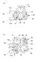
Next, second to sixth embodiments of the present invention will be described with reference to FIGS.
That is, FIG. 15A shows a second embodiment, and the
[0087]
FIG. 15B shows the third embodiment. In the modification of the second embodiment described above, the
[0088]
FIG. 15C shows a fourth embodiment. The
[0089]
Further, FIG. 16A shows a fifth embodiment. The
[0090]
FIG. 16 (b) shows a sixth embodiment. The
[0091]
In the above-described embodiment, the transfer means 51 has a form in which the
[0092]
In the above-described embodiment, the transfer means 51 has a form in which the
[0093]
In the embodiment described above, the fixed
[0094]
In the above-described embodiment, the
[0095]
In the embodiment described above, the
[0096]
In the above-described embodiment, the storage means 111 a and the delivery means 111 b are provided corresponding to the two fixed
[0098]
In the above-described embodiment, a form in which the storage means 151 is arranged in a state of being continuous with the unloading means 111b is shown, but this is a form in which the storage means is also arranged on the warehousing means 111a side, For example, the
[0099]
In the above-described embodiment, the loading /
[0100]
In the above-described embodiment, the
[0101]
In the above-described embodiment, the
[0102]
In the above-described embodiment, the
[0103]
In the above-described embodiment, in order to deliver the
[0104]
In the above-described embodiment, the
[0105]
【The invention's effect】
According to the first aspect of the present invention described above, the rotating shelf is rotated around the rotating shelf axis, and the intended load receiving portion is positioned at the overlapping portion of the rotating circle path and the transfer circle path. The loading / unloading portion can be loaded and unloaded by the transfer means. Further, by rotating the transfer action part of the transfer means around the axis of the transfer means, it is possible to load / unload the fixed shelf with the transfer means.
[0106]
In this way, since the transfer means does not perform traveling movement only by rotating the transfer operation section, the occupied space for traveling movement etc. can be made unnecessary, and the whole including the rotating shelf and the fixed shelf Can be configured compactly. In addition, the storage amount can be increased by the rotating shelf and the fixed shelf, and the transfer means without the traveling configuration can lower the transfer action part to near the floor, thereby lowering the storage level of the rotating shelf and the fixed shelf accordingly. It will be possible to increase the storage amount. Therefore, it can be easily and suitably employed in a place where a clean space such as a clean room is desired to be as narrow as possible.
[0107]
In addition, the load receiving part group of the rotating shelf and the load supporting part group of the fixed shelf can increase the storage amount by making the maximum use of the vertical height, while eliminating the load receiving part and the load supporting part. The loading / unloading means arranged using the space portion can be smoothly and smoothly loaded and unloaded from the outside without much reducing the storage amount.In that case, the storage means can be made low in volume and compact.
Furthermore, the loading of the load is performed by first placing the load on the temporary receiving body at the outer end portion of the loading / unloading means, and lifting the load on the temporary receiving body by the raising and lowering movement of the lifting and lowering body. The load is moved to the inside of the surrounding wall through the penetrating portion and then stopped at the inner end portion, so that the load can be positioned in the space portion and can be received by the operation of the transfer means. Also, the loading and unloading of the load is performed by first operating the transfer means to place the load on the inner end portion of the main body of the loading and unloading means, and lifting the lifting body to lift the load, and then lifting the lifting body to the outer end portion. The load can be transferred to the outside through the penetrating portion and then stopped at the outer end portion, and the elevator is lowered to place the load on the temporary receiver side.
[0108]
According to the second aspect of the present invention described above, the loading / unloading means can be disposed in the surrounding body without generating a useless space, so that the load storage facility can be made compact. According to the above-described third aspect of the present invention, by operating the loading / unloading means, the load can be loaded / unloaded between the clean room and the load delivery position by the transfer means, and thus can be easily adopted in a clean room or the like.
[Brief description of the drawings]
FIG. 1 is a transverse plan view of a load storage facility according to a first embodiment of the present invention.
FIG. 2 is an external perspective view of the cargo storage facility.
FIG. 3 is a longitudinal side view of the cargo storage facility.
FIG. 4 is a partially cutaway side view of a lower part of a rotating shelf in the same cargo storage facility.
FIG. 5 is a partially cutaway side view of the upper part of a rotating shelf in the same cargo storage facility.
FIG. 6 is a partially cutaway side view of the lower part of the transfer means in the cargo storage facility.
FIG. 7 is a partially cutaway side view of the upper part of the transfer means in the cargo storage facility.
FIG. 8 is a partially cutaway plan view of transfer means in the same cargo storage facility.
FIG. 9 is a side view of a fixed shelf in the cargo storage facility.
FIG. 10 is a plan view of a fixed shelf in the cargo storage facility.
FIG. 11 is a schematic plan view of a loading / unloading means part in the same cargo storage facility.
FIG. 12 is a partially cutaway side view of the warehousing means portion in the same cargo storage facility.
FIG. 13 is a partially cutaway front view of the storage means portion from the delivery means in the cargo storage facility.
FIG. 14 is a partially cutaway side view of a storage means portion in the cargo storage facility.
15 shows the second to fourth embodiments of the present invention, (a) is a schematic plan view showing the second embodiment, and (b) is a schematic plan view showing the third embodiment. FIG. (C) is a schematic plan view which shows 4th Embodiment.
16A and 16B show fifth and sixth embodiments of the present invention, FIG. 16A is a schematic plan view showing the fifth embodiment, and FIG. 16B is a schematic plan view showing the sixth embodiment; It is.
[Explanation of symbols]
3 Filter
4 Grating floor
5 Clean room
7 Cassette (load)
8 Fitting part
10 Load storage facilities
11 Enclosure
17 Cargo storage room (cargo storage space)
21 rotating shelf
22 rotating shelf axis
23 rotating circle path
26 Rotating body
32 Receiving part
35 Positioning pin
41 Rotating shelf driving means
51 Transfer means
52 Transfer axis
53 Transfer Circle Route
55 Post body
60 Lifting part
61 Lifting drive means
70 Rotating body
73 Rotation drive means
81 Transfer action part
82 Positioning pin
90 Exit / exit drive means
101 fixed shelf
103 Load support
106 Positioning pin
107 space
109 lines
110a Entry through part
110b Unloading penetration
111a Receipt means (entrance / exit means)
111b Unloading means (incoming and outgoing means)
113 Temporary receptacle
115 Positioning pin
117 Moving member
118 Mobile device
125 Lifting device
133 Lifting member
135 Swivel
142 Lifting body
143 Positioning pin
145 Entry / exit direction
148 Loading / unloading department
151 Storage means
153 Temporary receptacle
155 Positioning pin
157 Moving member
158 Mobile device
165 Lifting device
174 Lifting body
180 Bulkhead
181 Load transport means
191 Upper conveying means
A Clean air
Claims (3)
Translated fromJapanesePriority Applications (5)
| Application Number | Priority Date | Filing Date | Title |
|---|---|---|---|
| JP2001262584AJP3832293B2 (en) | 2001-08-31 | 2001-08-31 | Load storage equipment |
| KR10-2002-0048661AKR100518406B1 (en) | 2001-08-31 | 2002-08-17 | Load storage equipment |
| TW091119498ATW546234B (en) | 2001-08-31 | 2002-08-28 | Load storage equipment |
| CNB021321027ACN1204026C (en) | 2001-08-31 | 2002-08-30 | Goods maintaining apparatus |
| US10/235,037US6722837B2 (en) | 2001-08-31 | 2002-09-03 | Load storage equipment |
Applications Claiming Priority (1)
| Application Number | Priority Date | Filing Date | Title |
|---|---|---|---|
| JP2001262584AJP3832293B2 (en) | 2001-08-31 | 2001-08-31 | Load storage equipment |
Publications (2)
| Publication Number | Publication Date |
|---|---|
| JP2003072917A JP2003072917A (en) | 2003-03-12 |
| JP3832293B2true JP3832293B2 (en) | 2006-10-11 |
Family
ID=19089462
Family Applications (1)
| Application Number | Title | Priority Date | Filing Date |
|---|---|---|---|
| JP2001262584AExpired - Fee RelatedJP3832293B2 (en) | 2001-08-31 | 2001-08-31 | Load storage equipment |
Country Status (5)
| Country | Link |
|---|---|
| US (1) | US6722837B2 (en) |
| JP (1) | JP3832293B2 (en) |
| KR (1) | KR100518406B1 (en) |
| CN (1) | CN1204026C (en) |
| TW (1) | TW546234B (en) |
Families Citing this family (374)
| Publication number | Priority date | Publication date | Assignee | Title |
|---|---|---|---|---|
| TW522127B (en)* | 2001-02-21 | 2003-03-01 | Daifuku Kk | Cargo storage facility |
| JP3832293B2 (en)* | 2001-08-31 | 2006-10-11 | 株式会社ダイフク | Load storage equipment |
| JP3832292B2 (en)* | 2001-08-31 | 2006-10-11 | 株式会社ダイフク | Load storage equipment |
| TWI290901B (en)* | 2003-06-23 | 2007-12-11 | Au Optronics Corp | Warehousing conveyor system |
| KR100701220B1 (en)* | 2004-11-15 | 2007-03-29 | 한국정보통신대학교 산학협력단 | InfoHive information transmission and display device |
| US7510067B2 (en)* | 2005-07-14 | 2009-03-31 | Easom Automation Systems, Inc. | Low profile turntable assembly |
| JP5062485B2 (en)* | 2008-04-09 | 2012-10-31 | 株式会社ダイフク | Goods transport equipment |
| US10378106B2 (en) | 2008-11-14 | 2019-08-13 | Asm Ip Holding B.V. | Method of forming insulation film by modified PEALD |
| JP5131558B2 (en)* | 2008-12-02 | 2013-01-30 | 株式会社ダイフク | Article conveying device |
| US9394608B2 (en) | 2009-04-06 | 2016-07-19 | Asm America, Inc. | Semiconductor processing reactor and components thereof |
| CN101628663B (en)* | 2009-08-13 | 2011-12-14 | 北京清大天达光电科技有限公司 | Rotary conveying device of heavy load workpiece |
| US8802201B2 (en) | 2009-08-14 | 2014-08-12 | Asm America, Inc. | Systems and methods for thin-film deposition of metal oxides using excited nitrogen-oxygen species |
| US8759084B2 (en) | 2010-01-22 | 2014-06-24 | Michael J. Nichols | Self-sterilizing automated incubator |
| JP5370775B2 (en)* | 2010-02-01 | 2013-12-18 | 株式会社ダイフク | Goods storage facility |
| US8899903B1 (en)* | 2010-05-18 | 2014-12-02 | The Boeing Company | Vehicle base station |
| CN102114961B (en)* | 2010-12-31 | 2012-12-12 | 苏州艾隆科技有限公司 | Rotary automatic medicine delivery machine |
| CN102167209B (en)* | 2011-03-21 | 2014-10-29 | 王惠云 | Real-time article warehousing management system |
| US9312155B2 (en) | 2011-06-06 | 2016-04-12 | Asm Japan K.K. | High-throughput semiconductor-processing apparatus equipped with multiple dual-chamber modules |
| US10364496B2 (en) | 2011-06-27 | 2019-07-30 | Asm Ip Holding B.V. | Dual section module having shared and unshared mass flow controllers |
| US10854498B2 (en) | 2011-07-15 | 2020-12-01 | Asm Ip Holding B.V. | Wafer-supporting device and method for producing same |
| US20130023129A1 (en) | 2011-07-20 | 2013-01-24 | Asm America, Inc. | Pressure transmitter for a semiconductor processing environment |
| US9017481B1 (en) | 2011-10-28 | 2015-04-28 | Asm America, Inc. | Process feed management for semiconductor substrate processing |
| US9659799B2 (en) | 2012-08-28 | 2017-05-23 | Asm Ip Holding B.V. | Systems and methods for dynamic semiconductor process scheduling |
| US10714315B2 (en) | 2012-10-12 | 2020-07-14 | Asm Ip Holdings B.V. | Semiconductor reaction chamber showerhead |
| US20160376700A1 (en) | 2013-02-01 | 2016-12-29 | Asm Ip Holding B.V. | System for treatment of deposition reactor |
| US9484191B2 (en) | 2013-03-08 | 2016-11-01 | Asm Ip Holding B.V. | Pulsed remote plasma method and system |
| US9589770B2 (en) | 2013-03-08 | 2017-03-07 | Asm Ip Holding B.V. | Method and systems for in-situ formation of intermediate reactive species |
| US9240412B2 (en) | 2013-09-27 | 2016-01-19 | Asm Ip Holding B.V. | Semiconductor structure and device and methods of forming same using selective epitaxial process |
| US10683571B2 (en) | 2014-02-25 | 2020-06-16 | Asm Ip Holding B.V. | Gas supply manifold and method of supplying gases to chamber using same |
| JP6052209B2 (en)* | 2014-03-11 | 2016-12-27 | 株式会社ダイフク | Container transfer equipment |
| US10167557B2 (en) | 2014-03-18 | 2019-01-01 | Asm Ip Holding B.V. | Gas distribution system, reactor including the system, and methods of using the same |
| US11015245B2 (en) | 2014-03-19 | 2021-05-25 | Asm Ip Holding B.V. | Gas-phase reactor and system having exhaust plenum and components thereof |
| US10858737B2 (en) | 2014-07-28 | 2020-12-08 | Asm Ip Holding B.V. | Showerhead assembly and components thereof |
| US9890456B2 (en) | 2014-08-21 | 2018-02-13 | Asm Ip Holding B.V. | Method and system for in situ formation of gas-phase compounds |
| KR101999836B1 (en)* | 2014-08-26 | 2019-07-12 | 무라다기카이가부시끼가이샤 | Sorting system and sorting method |
| US10941490B2 (en) | 2014-10-07 | 2021-03-09 | Asm Ip Holding B.V. | Multiple temperature range susceptor, assembly, reactor and system including the susceptor, and methods of using the same |
| US9657845B2 (en) | 2014-10-07 | 2017-05-23 | Asm Ip Holding B.V. | Variable conductance gas distribution apparatus and method |
| CN104370046B (en)* | 2014-11-11 | 2017-02-01 | 厦门积硕科技股份有限公司 | Method and device for storing samples or taking out samples for check |
| KR102263121B1 (en) | 2014-12-22 | 2021-06-09 | 에이에스엠 아이피 홀딩 비.브이. | Semiconductor device and manufacuring method thereof |
| US10529542B2 (en) | 2015-03-11 | 2020-01-07 | Asm Ip Holdings B.V. | Cross-flow reactor and method |
| US10276355B2 (en) | 2015-03-12 | 2019-04-30 | Asm Ip Holding B.V. | Multi-zone reactor, system including the reactor, and method of using the same |
| JP6332133B2 (en) | 2015-05-14 | 2018-05-30 | 株式会社ダイフク | Container transfer equipment |
| US10458018B2 (en) | 2015-06-26 | 2019-10-29 | Asm Ip Holding B.V. | Structures including metal carbide material, devices including the structures, and methods of forming same |
| US10600673B2 (en) | 2015-07-07 | 2020-03-24 | Asm Ip Holding B.V. | Magnetic susceptor to baseplate seal |
| US9960072B2 (en) | 2015-09-29 | 2018-05-01 | Asm Ip Holding B.V. | Variable adjustment for precise matching of multiple chamber cavity housings |
| US10211308B2 (en) | 2015-10-21 | 2019-02-19 | Asm Ip Holding B.V. | NbMC layers |
| US10322384B2 (en) | 2015-11-09 | 2019-06-18 | Asm Ip Holding B.V. | Counter flow mixer for process chamber |
| US11139308B2 (en) | 2015-12-29 | 2021-10-05 | Asm Ip Holding B.V. | Atomic layer deposition of III-V compounds to form V-NAND devices |
| US10468251B2 (en) | 2016-02-19 | 2019-11-05 | Asm Ip Holding B.V. | Method for forming spacers using silicon nitride film for spacer-defined multiple patterning |
| US10529554B2 (en) | 2016-02-19 | 2020-01-07 | Asm Ip Holding B.V. | Method for forming silicon nitride film selectively on sidewalls or flat surfaces of trenches |
| US10501866B2 (en) | 2016-03-09 | 2019-12-10 | Asm Ip Holding B.V. | Gas distribution apparatus for improved film uniformity in an epitaxial system |
| US10343920B2 (en) | 2016-03-18 | 2019-07-09 | Asm Ip Holding B.V. | Aligned carbon nanotubes |
| US9892913B2 (en) | 2016-03-24 | 2018-02-13 | Asm Ip Holding B.V. | Radial and thickness control via biased multi-port injection settings |
| US10865475B2 (en) | 2016-04-21 | 2020-12-15 | Asm Ip Holding B.V. | Deposition of metal borides and silicides |
| US10190213B2 (en) | 2016-04-21 | 2019-01-29 | Asm Ip Holding B.V. | Deposition of metal borides |
| US10367080B2 (en) | 2016-05-02 | 2019-07-30 | Asm Ip Holding B.V. | Method of forming a germanium oxynitride film |
| US10032628B2 (en) | 2016-05-02 | 2018-07-24 | Asm Ip Holding B.V. | Source/drain performance through conformal solid state doping |
| KR102592471B1 (en) | 2016-05-17 | 2023-10-20 | 에이에스엠 아이피 홀딩 비.브이. | Method of forming metal interconnection and method of fabricating semiconductor device using the same |
| US11453943B2 (en) | 2016-05-25 | 2022-09-27 | Asm Ip Holding B.V. | Method for forming carbon-containing silicon/metal oxide or nitride film by ALD using silicon precursor and hydrocarbon precursor |
| US10388509B2 (en) | 2016-06-28 | 2019-08-20 | Asm Ip Holding B.V. | Formation of epitaxial layers via dislocation filtering |
| US10612137B2 (en) | 2016-07-08 | 2020-04-07 | Asm Ip Holdings B.V. | Organic reactants for atomic layer deposition |
| US9859151B1 (en) | 2016-07-08 | 2018-01-02 | Asm Ip Holding B.V. | Selective film deposition method to form air gaps |
| US10714385B2 (en) | 2016-07-19 | 2020-07-14 | Asm Ip Holding B.V. | Selective deposition of tungsten |
| KR102354490B1 (en) | 2016-07-27 | 2022-01-21 | 에이에스엠 아이피 홀딩 비.브이. | Method of processing a substrate |
| US9887082B1 (en) | 2016-07-28 | 2018-02-06 | Asm Ip Holding B.V. | Method and apparatus for filling a gap |
| KR102532607B1 (en) | 2016-07-28 | 2023-05-15 | 에이에스엠 아이피 홀딩 비.브이. | Substrate processing apparatus and method of operating the same |
| US9812320B1 (en) | 2016-07-28 | 2017-11-07 | Asm Ip Holding B.V. | Method and apparatus for filling a gap |
| US10395919B2 (en) | 2016-07-28 | 2019-08-27 | Asm Ip Holding B.V. | Method and apparatus for filling a gap |
| KR102613349B1 (en) | 2016-08-25 | 2023-12-14 | 에이에스엠 아이피 홀딩 비.브이. | Exhaust apparatus and substrate processing apparatus and thin film fabricating method using the same |
| CN106241170B (en)* | 2016-09-23 | 2018-09-21 | 深圳百泰投资控股集团有限公司 | A kind of automated warehouse management method of jewelry product |
| US10410943B2 (en) | 2016-10-13 | 2019-09-10 | Asm Ip Holding B.V. | Method for passivating a surface of a semiconductor and related systems |
| US10643826B2 (en) | 2016-10-26 | 2020-05-05 | Asm Ip Holdings B.V. | Methods for thermally calibrating reaction chambers |
| US11532757B2 (en) | 2016-10-27 | 2022-12-20 | Asm Ip Holding B.V. | Deposition of charge trapping layers |
| US10229833B2 (en) | 2016-11-01 | 2019-03-12 | Asm Ip Holding B.V. | Methods for forming a transition metal nitride film on a substrate by atomic layer deposition and related semiconductor device structures |
| US10643904B2 (en) | 2016-11-01 | 2020-05-05 | Asm Ip Holdings B.V. | Methods for forming a semiconductor device and related semiconductor device structures |
| US10714350B2 (en) | 2016-11-01 | 2020-07-14 | ASM IP Holdings, B.V. | Methods for forming a transition metal niobium nitride film on a substrate by atomic layer deposition and related semiconductor device structures |
| US10435790B2 (en) | 2016-11-01 | 2019-10-08 | Asm Ip Holding B.V. | Method of subatmospheric plasma-enhanced ALD using capacitively coupled electrodes with narrow gap |
| US10134757B2 (en) | 2016-11-07 | 2018-11-20 | Asm Ip Holding B.V. | Method of processing a substrate and a device manufactured by using the method |
| KR102546317B1 (en) | 2016-11-15 | 2023-06-21 | 에이에스엠 아이피 홀딩 비.브이. | Gas supply unit and substrate processing apparatus including the same |
| US10340135B2 (en) | 2016-11-28 | 2019-07-02 | Asm Ip Holding B.V. | Method of topologically restricted plasma-enhanced cyclic deposition of silicon or metal nitride |
| US10672639B2 (en)* | 2016-12-07 | 2020-06-02 | Taiwan Semiconductor Manufacturing Co., Ltd. | Method for automatic sending cassette pod |
| KR102762543B1 (en) | 2016-12-14 | 2025-02-05 | 에이에스엠 아이피 홀딩 비.브이. | Substrate processing apparatus |
| US11581186B2 (en) | 2016-12-15 | 2023-02-14 | Asm Ip Holding B.V. | Sequential infiltration synthesis apparatus |
| US11447861B2 (en) | 2016-12-15 | 2022-09-20 | Asm Ip Holding B.V. | Sequential infiltration synthesis apparatus and a method of forming a patterned structure |
| KR102700194B1 (en) | 2016-12-19 | 2024-08-28 | 에이에스엠 아이피 홀딩 비.브이. | Substrate processing apparatus |
| US10269558B2 (en) | 2016-12-22 | 2019-04-23 | Asm Ip Holding B.V. | Method of forming a structure on a substrate |
| US10867788B2 (en) | 2016-12-28 | 2020-12-15 | Asm Ip Holding B.V. | Method of forming a structure on a substrate |
| US11390950B2 (en) | 2017-01-10 | 2022-07-19 | Asm Ip Holding B.V. | Reactor system and method to reduce residue buildup during a film deposition process |
| US10655221B2 (en) | 2017-02-09 | 2020-05-19 | Asm Ip Holding B.V. | Method for depositing oxide film by thermal ALD and PEALD |
| US10468261B2 (en) | 2017-02-15 | 2019-11-05 | Asm Ip Holding B.V. | Methods for forming a metallic film on a substrate by cyclical deposition and related semiconductor device structures |
| US10529563B2 (en) | 2017-03-29 | 2020-01-07 | Asm Ip Holdings B.V. | Method for forming doped metal oxide films on a substrate by cyclical deposition and related semiconductor device structures |
| US10283353B2 (en) | 2017-03-29 | 2019-05-07 | Asm Ip Holding B.V. | Method of reforming insulating film deposited on substrate with recess pattern |
| KR102457289B1 (en) | 2017-04-25 | 2022-10-21 | 에이에스엠 아이피 홀딩 비.브이. | Method for depositing a thin film and manufacturing a semiconductor device |
| US10446393B2 (en) | 2017-05-08 | 2019-10-15 | Asm Ip Holding B.V. | Methods for forming silicon-containing epitaxial layers and related semiconductor device structures |
| US10770286B2 (en) | 2017-05-08 | 2020-09-08 | Asm Ip Holdings B.V. | Methods for selectively forming a silicon nitride film on a substrate and related semiconductor device structures |
| US10892156B2 (en) | 2017-05-08 | 2021-01-12 | Asm Ip Holding B.V. | Methods for forming a silicon nitride film on a substrate and related semiconductor device structures |
| US10504742B2 (en) | 2017-05-31 | 2019-12-10 | Asm Ip Holding B.V. | Method of atomic layer etching using hydrogen plasma |
| US10886123B2 (en) | 2017-06-02 | 2021-01-05 | Asm Ip Holding B.V. | Methods for forming low temperature semiconductor layers and related semiconductor device structures |
| US12040200B2 (en) | 2017-06-20 | 2024-07-16 | Asm Ip Holding B.V. | Semiconductor processing apparatus and methods for calibrating a semiconductor processing apparatus |
| US11306395B2 (en) | 2017-06-28 | 2022-04-19 | Asm Ip Holding B.V. | Methods for depositing a transition metal nitride film on a substrate by atomic layer deposition and related deposition apparatus |
| US10685834B2 (en) | 2017-07-05 | 2020-06-16 | Asm Ip Holdings B.V. | Methods for forming a silicon germanium tin layer and related semiconductor device structures |
| KR20190009245A (en) | 2017-07-18 | 2019-01-28 | 에이에스엠 아이피 홀딩 비.브이. | Methods for forming a semiconductor device structure and related semiconductor device structures |
| US10541333B2 (en) | 2017-07-19 | 2020-01-21 | Asm Ip Holding B.V. | Method for depositing a group IV semiconductor and related semiconductor device structures |
| US11018002B2 (en) | 2017-07-19 | 2021-05-25 | Asm Ip Holding B.V. | Method for selectively depositing a Group IV semiconductor and related semiconductor device structures |
| US11374112B2 (en) | 2017-07-19 | 2022-06-28 | Asm Ip Holding B.V. | Method for depositing a group IV semiconductor and related semiconductor device structures |
| US10590535B2 (en) | 2017-07-26 | 2020-03-17 | Asm Ip Holdings B.V. | Chemical treatment, deposition and/or infiltration apparatus and method for using the same |
| US10312055B2 (en) | 2017-07-26 | 2019-06-04 | Asm Ip Holding B.V. | Method of depositing film by PEALD using negative bias |
| US10605530B2 (en) | 2017-07-26 | 2020-03-31 | Asm Ip Holding B.V. | Assembly of a liner and a flange for a vertical furnace as well as the liner and the vertical furnace |
| TWI815813B (en) | 2017-08-04 | 2023-09-21 | 荷蘭商Asm智慧財產控股公司 | Showerhead assembly for distributing a gas within a reaction chamber |
| US10770336B2 (en) | 2017-08-08 | 2020-09-08 | Asm Ip Holding B.V. | Substrate lift mechanism and reactor including same |
| US10692741B2 (en) | 2017-08-08 | 2020-06-23 | Asm Ip Holdings B.V. | Radiation shield |
| US10249524B2 (en) | 2017-08-09 | 2019-04-02 | Asm Ip Holding B.V. | Cassette holder assembly for a substrate cassette and holding member for use in such assembly |
| US11139191B2 (en) | 2017-08-09 | 2021-10-05 | Asm Ip Holding B.V. | Storage apparatus for storing cassettes for substrates and processing apparatus equipped therewith |
| US11769682B2 (en) | 2017-08-09 | 2023-09-26 | Asm Ip Holding B.V. | Storage apparatus for storing cassettes for substrates and processing apparatus equipped therewith |
| USD900036S1 (en) | 2017-08-24 | 2020-10-27 | Asm Ip Holding B.V. | Heater electrical connector and adapter |
| US11830730B2 (en) | 2017-08-29 | 2023-11-28 | Asm Ip Holding B.V. | Layer forming method and apparatus |
| US11056344B2 (en) | 2017-08-30 | 2021-07-06 | Asm Ip Holding B.V. | Layer forming method |
| KR102491945B1 (en) | 2017-08-30 | 2023-01-26 | 에이에스엠 아이피 홀딩 비.브이. | Substrate processing apparatus |
| US11295980B2 (en) | 2017-08-30 | 2022-04-05 | Asm Ip Holding B.V. | Methods for depositing a molybdenum metal film over a dielectric surface of a substrate by a cyclical deposition process and related semiconductor device structures |
| KR102401446B1 (en) | 2017-08-31 | 2022-05-24 | 에이에스엠 아이피 홀딩 비.브이. | Substrate processing apparatus |
| US10607895B2 (en) | 2017-09-18 | 2020-03-31 | Asm Ip Holdings B.V. | Method for forming a semiconductor device structure comprising a gate fill metal |
| KR102630301B1 (en) | 2017-09-21 | 2024-01-29 | 에이에스엠 아이피 홀딩 비.브이. | Method of sequential infiltration synthesis treatment of infiltrateable material and structures and devices formed using same |
| US10844484B2 (en) | 2017-09-22 | 2020-11-24 | Asm Ip Holding B.V. | Apparatus for dispensing a vapor phase reactant to a reaction chamber and related methods |
| US10658205B2 (en) | 2017-09-28 | 2020-05-19 | Asm Ip Holdings B.V. | Chemical dispensing apparatus and methods for dispensing a chemical to a reaction chamber |
| US10403504B2 (en) | 2017-10-05 | 2019-09-03 | Asm Ip Holding B.V. | Method for selectively depositing a metallic film on a substrate |
| US10319588B2 (en) | 2017-10-10 | 2019-06-11 | Asm Ip Holding B.V. | Method for depositing a metal chalcogenide on a substrate by cyclical deposition |
| US10923344B2 (en) | 2017-10-30 | 2021-02-16 | Asm Ip Holding B.V. | Methods for forming a semiconductor structure and related semiconductor structures |
| CN107840056B (en)* | 2017-11-13 | 2020-02-04 | 英华达(上海)科技有限公司 | Warehousing system |
| KR102443047B1 (en) | 2017-11-16 | 2022-09-14 | 에이에스엠 아이피 홀딩 비.브이. | Method of processing a substrate and a device manufactured by the same |
| US10910262B2 (en) | 2017-11-16 | 2021-02-02 | Asm Ip Holding B.V. | Method of selectively depositing a capping layer structure on a semiconductor device structure |
| US11022879B2 (en) | 2017-11-24 | 2021-06-01 | Asm Ip Holding B.V. | Method of forming an enhanced unexposed photoresist layer |
| WO2019103613A1 (en) | 2017-11-27 | 2019-05-31 | Asm Ip Holding B.V. | A storage device for storing wafer cassettes for use with a batch furnace |
| CN111344522B (en) | 2017-11-27 | 2022-04-12 | 阿斯莫Ip控股公司 | Including clean mini-environment device |
| US10290508B1 (en) | 2017-12-05 | 2019-05-14 | Asm Ip Holding B.V. | Method for forming vertical spacers for spacer-defined patterning |
| CN109956246A (en)* | 2017-12-25 | 2019-07-02 | 北京京东尚科信息技术有限公司 | Cache library, cache device, picking line, three-dimensional warehouse and picking method |
| US10872771B2 (en) | 2018-01-16 | 2020-12-22 | Asm Ip Holding B. V. | Method for depositing a material film on a substrate within a reaction chamber by a cyclical deposition process and related device structures |
| TWI799494B (en) | 2018-01-19 | 2023-04-21 | 荷蘭商Asm 智慧財產控股公司 | Deposition method |
| KR102695659B1 (en) | 2018-01-19 | 2024-08-14 | 에이에스엠 아이피 홀딩 비.브이. | Method for depositing a gap filling layer by plasma assisted deposition |
| USD903477S1 (en) | 2018-01-24 | 2020-12-01 | Asm Ip Holdings B.V. | Metal clamp |
| US11018047B2 (en) | 2018-01-25 | 2021-05-25 | Asm Ip Holding B.V. | Hybrid lift pin |
| USD880437S1 (en) | 2018-02-01 | 2020-04-07 | Asm Ip Holding B.V. | Gas supply plate for semiconductor manufacturing apparatus |
| US10535516B2 (en) | 2018-02-01 | 2020-01-14 | Asm Ip Holdings B.V. | Method for depositing a semiconductor structure on a surface of a substrate and related semiconductor structures |
| US11081345B2 (en) | 2018-02-06 | 2021-08-03 | Asm Ip Holding B.V. | Method of post-deposition treatment for silicon oxide film |
| US10896820B2 (en) | 2018-02-14 | 2021-01-19 | Asm Ip Holding B.V. | Method for depositing a ruthenium-containing film on a substrate by a cyclical deposition process |
| WO2019158960A1 (en) | 2018-02-14 | 2019-08-22 | Asm Ip Holding B.V. | A method for depositing a ruthenium-containing film on a substrate by a cyclical deposition process |
| US10731249B2 (en) | 2018-02-15 | 2020-08-04 | Asm Ip Holding B.V. | Method of forming a transition metal containing film on a substrate by a cyclical deposition process, a method for supplying a transition metal halide compound to a reaction chamber, and related vapor deposition apparatus |
| US10658181B2 (en) | 2018-02-20 | 2020-05-19 | Asm Ip Holding B.V. | Method of spacer-defined direct patterning in semiconductor fabrication |
| KR102636427B1 (en) | 2018-02-20 | 2024-02-13 | 에이에스엠 아이피 홀딩 비.브이. | Substrate processing method and apparatus |
| US10975470B2 (en) | 2018-02-23 | 2021-04-13 | Asm Ip Holding B.V. | Apparatus for detecting or monitoring for a chemical precursor in a high temperature environment |
| US11473195B2 (en) | 2018-03-01 | 2022-10-18 | Asm Ip Holding B.V. | Semiconductor processing apparatus and a method for processing a substrate |
| US11629406B2 (en) | 2018-03-09 | 2023-04-18 | Asm Ip Holding B.V. | Semiconductor processing apparatus comprising one or more pyrometers for measuring a temperature of a substrate during transfer of the substrate |
| US11114283B2 (en) | 2018-03-16 | 2021-09-07 | Asm Ip Holding B.V. | Reactor, system including the reactor, and methods of manufacturing and using same |
| KR102646467B1 (en) | 2018-03-27 | 2024-03-11 | 에이에스엠 아이피 홀딩 비.브이. | Method of forming an electrode on a substrate and a semiconductor device structure including an electrode |
| US11088002B2 (en) | 2018-03-29 | 2021-08-10 | Asm Ip Holding B.V. | Substrate rack and a substrate processing system and method |
| US10510536B2 (en) | 2018-03-29 | 2019-12-17 | Asm Ip Holding B.V. | Method of depositing a co-doped polysilicon film on a surface of a substrate within a reaction chamber |
| US11230766B2 (en) | 2018-03-29 | 2022-01-25 | Asm Ip Holding B.V. | Substrate processing apparatus and method |
| KR102501472B1 (en) | 2018-03-30 | 2023-02-20 | 에이에스엠 아이피 홀딩 비.브이. | Substrate processing method |
| KR102600229B1 (en) | 2018-04-09 | 2023-11-10 | 에이에스엠 아이피 홀딩 비.브이. | Substrate supporting device, substrate processing apparatus including the same and substrate processing method |
| TWI811348B (en) | 2018-05-08 | 2023-08-11 | 荷蘭商Asm 智慧財產控股公司 | Methods for depositing an oxide film on a substrate by a cyclical deposition process and related device structures |
| US12025484B2 (en) | 2018-05-08 | 2024-07-02 | Asm Ip Holding B.V. | Thin film forming method |
| US12272527B2 (en) | 2018-05-09 | 2025-04-08 | Asm Ip Holding B.V. | Apparatus for use with hydrogen radicals and method of using same |
| KR20190129718A (en) | 2018-05-11 | 2019-11-20 | 에이에스엠 아이피 홀딩 비.브이. | Methods for forming a doped metal carbide film on a substrate and related semiconductor device structures |
| KR102596988B1 (en) | 2018-05-28 | 2023-10-31 | 에이에스엠 아이피 홀딩 비.브이. | Method of processing a substrate and a device manufactured by the same |
| US11718913B2 (en) | 2018-06-04 | 2023-08-08 | Asm Ip Holding B.V. | Gas distribution system and reactor system including same |
| TWI840362B (en) | 2018-06-04 | 2024-05-01 | 荷蘭商Asm Ip私人控股有限公司 | Wafer handling chamber with moisture reduction |
| US11286562B2 (en) | 2018-06-08 | 2022-03-29 | Asm Ip Holding B.V. | Gas-phase chemical reactor and method of using same |
| KR102568797B1 (en) | 2018-06-21 | 2023-08-21 | 에이에스엠 아이피 홀딩 비.브이. | Substrate processing system |
| US10797133B2 (en) | 2018-06-21 | 2020-10-06 | Asm Ip Holding B.V. | Method for depositing a phosphorus doped silicon arsenide film and related semiconductor device structures |
| TWI873894B (en) | 2018-06-27 | 2025-02-21 | 荷蘭商Asm Ip私人控股有限公司 | Cyclic deposition methods for forming metal-containing material and films and structures including the metal-containing material |
| KR102854019B1 (en) | 2018-06-27 | 2025-09-02 | 에이에스엠 아이피 홀딩 비.브이. | Periodic deposition method for forming a metal-containing material and films and structures comprising the metal-containing material |
| US10612136B2 (en) | 2018-06-29 | 2020-04-07 | ASM IP Holding, B.V. | Temperature-controlled flange and reactor system including same |
| KR102686758B1 (en) | 2018-06-29 | 2024-07-18 | 에이에스엠 아이피 홀딩 비.브이. | Method for depositing a thin film and manufacturing a semiconductor device |
| US10388513B1 (en) | 2018-07-03 | 2019-08-20 | Asm Ip Holding B.V. | Method for depositing silicon-free carbon-containing film as gap-fill layer by pulse plasma-assisted deposition |
| US10755922B2 (en) | 2018-07-03 | 2020-08-25 | Asm Ip Holding B.V. | Method for depositing silicon-free carbon-containing film as gap-fill layer by pulse plasma-assisted deposition |
| US10767789B2 (en) | 2018-07-16 | 2020-09-08 | Asm Ip Holding B.V. | Diaphragm valves, valve components, and methods for forming valve components |
| US10483099B1 (en) | 2018-07-26 | 2019-11-19 | Asm Ip Holding B.V. | Method for forming thermally stable organosilicon polymer film |
| US11053591B2 (en) | 2018-08-06 | 2021-07-06 | Asm Ip Holding B.V. | Multi-port gas injection system and reactor system including same |
| US10883175B2 (en) | 2018-08-09 | 2021-01-05 | Asm Ip Holding B.V. | Vertical furnace for processing substrates and a liner for use therein |
| US10829852B2 (en) | 2018-08-16 | 2020-11-10 | Asm Ip Holding B.V. | Gas distribution device for a wafer processing apparatus |
| US11430674B2 (en) | 2018-08-22 | 2022-08-30 | Asm Ip Holding B.V. | Sensor array, apparatus for dispensing a vapor phase reactant to a reaction chamber and related methods |
| KR102707956B1 (en) | 2018-09-11 | 2024-09-19 | 에이에스엠 아이피 홀딩 비.브이. | Method for deposition of a thin film |
| US11024523B2 (en) | 2018-09-11 | 2021-06-01 | Asm Ip Holding B.V. | Substrate processing apparatus and method |
| US11049751B2 (en) | 2018-09-14 | 2021-06-29 | Asm Ip Holding B.V. | Cassette supply system to store and handle cassettes and processing apparatus equipped therewith |
| CN110970344B (en) | 2018-10-01 | 2024-10-25 | Asmip控股有限公司 | Substrate holding apparatus, system comprising the same and method of using the same |
| US11232963B2 (en) | 2018-10-03 | 2022-01-25 | Asm Ip Holding B.V. | Substrate processing apparatus and method |
| KR102592699B1 (en) | 2018-10-08 | 2023-10-23 | 에이에스엠 아이피 홀딩 비.브이. | Substrate support unit and apparatuses for depositing thin film and processing the substrate including the same |
| US10847365B2 (en) | 2018-10-11 | 2020-11-24 | Asm Ip Holding B.V. | Method of forming conformal silicon carbide film by cyclic CVD |
| US10811256B2 (en) | 2018-10-16 | 2020-10-20 | Asm Ip Holding B.V. | Method for etching a carbon-containing feature |
| KR102605121B1 (en) | 2018-10-19 | 2023-11-23 | 에이에스엠 아이피 홀딩 비.브이. | Substrate processing apparatus and substrate processing method |
| KR102546322B1 (en) | 2018-10-19 | 2023-06-21 | 에이에스엠 아이피 홀딩 비.브이. | Substrate processing apparatus and substrate processing method |
| USD948463S1 (en) | 2018-10-24 | 2022-04-12 | Asm Ip Holding B.V. | Susceptor for semiconductor substrate supporting apparatus |
| US10381219B1 (en) | 2018-10-25 | 2019-08-13 | Asm Ip Holding B.V. | Methods for forming a silicon nitride film |
| US12378665B2 (en) | 2018-10-26 | 2025-08-05 | Asm Ip Holding B.V. | High temperature coatings for a preclean and etch apparatus and related methods |
| US11087997B2 (en) | 2018-10-31 | 2021-08-10 | Asm Ip Holding B.V. | Substrate processing apparatus for processing substrates |
| KR102748291B1 (en) | 2018-11-02 | 2024-12-31 | 에이에스엠 아이피 홀딩 비.브이. | Substrate support unit and substrate processing apparatus including the same |
| US11572620B2 (en) | 2018-11-06 | 2023-02-07 | Asm Ip Holding B.V. | Methods for selectively depositing an amorphous silicon film on a substrate |
| US11031242B2 (en) | 2018-11-07 | 2021-06-08 | Asm Ip Holding B.V. | Methods for depositing a boron doped silicon germanium film |
| US10818758B2 (en) | 2018-11-16 | 2020-10-27 | Asm Ip Holding B.V. | Methods for forming a metal silicate film on a substrate in a reaction chamber and related semiconductor device structures |
| US10847366B2 (en) | 2018-11-16 | 2020-11-24 | Asm Ip Holding B.V. | Methods for depositing a transition metal chalcogenide film on a substrate by a cyclical deposition process |
| US10559458B1 (en) | 2018-11-26 | 2020-02-11 | Asm Ip Holding B.V. | Method of forming oxynitride film |
| US12040199B2 (en) | 2018-11-28 | 2024-07-16 | Asm Ip Holding B.V. | Substrate processing apparatus for processing substrates |
| US11217444B2 (en) | 2018-11-30 | 2022-01-04 | Asm Ip Holding B.V. | Method for forming an ultraviolet radiation responsive metal oxide-containing film |
| KR102636428B1 (en) | 2018-12-04 | 2024-02-13 | 에이에스엠 아이피 홀딩 비.브이. | A method for cleaning a substrate processing apparatus |
| US11158513B2 (en) | 2018-12-13 | 2021-10-26 | Asm Ip Holding B.V. | Methods for forming a rhenium-containing film on a substrate by a cyclical deposition process and related semiconductor device structures |
| TWI874340B (en) | 2018-12-14 | 2025-03-01 | 荷蘭商Asm Ip私人控股有限公司 | Method of forming device structure, structure formed by the method and system for performing the method |
| TWI866480B (en) | 2019-01-17 | 2024-12-11 | 荷蘭商Asm Ip 私人控股有限公司 | Methods of forming a transition metal containing film on a substrate by a cyclical deposition process |
| KR102727227B1 (en) | 2019-01-22 | 2024-11-07 | 에이에스엠 아이피 홀딩 비.브이. | Semiconductor processing device |
| CN111524788B (en) | 2019-02-01 | 2023-11-24 | Asm Ip私人控股有限公司 | Method for forming topologically selective films of silicon oxide |
| KR102626263B1 (en) | 2019-02-20 | 2024-01-16 | 에이에스엠 아이피 홀딩 비.브이. | Cyclical deposition method including treatment step and apparatus for same |
| TWI873122B (en) | 2019-02-20 | 2025-02-21 | 荷蘭商Asm Ip私人控股有限公司 | Method of filling a recess formed within a surface of a substrate, semiconductor structure formed according to the method, and semiconductor processing apparatus |
| TWI838458B (en) | 2019-02-20 | 2024-04-11 | 荷蘭商Asm Ip私人控股有限公司 | Apparatus and methods for plug fill deposition in 3-d nand applications |
| TWI845607B (en) | 2019-02-20 | 2024-06-21 | 荷蘭商Asm Ip私人控股有限公司 | Cyclical deposition method and apparatus for filling a recess formed within a substrate surface |
| TWI842826B (en) | 2019-02-22 | 2024-05-21 | 荷蘭商Asm Ip私人控股有限公司 | Substrate processing apparatus and method for processing substrate |
| US11742198B2 (en) | 2019-03-08 | 2023-08-29 | Asm Ip Holding B.V. | Structure including SiOCN layer and method of forming same |
| KR102782593B1 (en) | 2019-03-08 | 2025-03-14 | 에이에스엠 아이피 홀딩 비.브이. | Structure Including SiOC Layer and Method of Forming Same |
| KR102858005B1 (en) | 2019-03-08 | 2025-09-09 | 에이에스엠 아이피 홀딩 비.브이. | Method for Selective Deposition of Silicon Nitride Layer and Structure Including Selectively-Deposited Silicon Nitride Layer |
| JP2020167398A (en) | 2019-03-28 | 2020-10-08 | エーエスエム・アイピー・ホールディング・ベー・フェー | Door openers and substrate processing equipment provided with door openers |
| KR102809999B1 (en) | 2019-04-01 | 2025-05-19 | 에이에스엠 아이피 홀딩 비.브이. | Method of manufacturing semiconductor device |
| KR20200123380A (en) | 2019-04-19 | 2020-10-29 | 에이에스엠 아이피 홀딩 비.브이. | Layer forming method and apparatus |
| KR20200125453A (en) | 2019-04-24 | 2020-11-04 | 에이에스엠 아이피 홀딩 비.브이. | Gas-phase reactor system and method of using same |
| KR20200130121A (en) | 2019-05-07 | 2020-11-18 | 에이에스엠 아이피 홀딩 비.브이. | Chemical source vessel with dip tube |
| US11289326B2 (en) | 2019-05-07 | 2022-03-29 | Asm Ip Holding B.V. | Method for reforming amorphous carbon polymer film |
| KR20200130652A (en) | 2019-05-10 | 2020-11-19 | 에이에스엠 아이피 홀딩 비.브이. | Method of depositing material onto a surface and structure formed according to the method |
| JP7598201B2 (en) | 2019-05-16 | 2024-12-11 | エーエスエム・アイピー・ホールディング・ベー・フェー | Wafer boat handling apparatus, vertical batch furnace and method |
| JP7612342B2 (en) | 2019-05-16 | 2025-01-14 | エーエスエム・アイピー・ホールディング・ベー・フェー | Wafer boat handling apparatus, vertical batch furnace and method |
| USD947913S1 (en) | 2019-05-17 | 2022-04-05 | Asm Ip Holding B.V. | Susceptor shaft |
| USD975665S1 (en) | 2019-05-17 | 2023-01-17 | Asm Ip Holding B.V. | Susceptor shaft |
| USD935572S1 (en) | 2019-05-24 | 2021-11-09 | Asm Ip Holding B.V. | Gas channel plate |
| USD922229S1 (en) | 2019-06-05 | 2021-06-15 | Asm Ip Holding B.V. | Device for controlling a temperature of a gas supply unit |
| KR20200141002A (en) | 2019-06-06 | 2020-12-17 | 에이에스엠 아이피 홀딩 비.브이. | Method of using a gas-phase reactor system including analyzing exhausted gas |
| KR20200141931A (en) | 2019-06-10 | 2020-12-21 | 에이에스엠 아이피 홀딩 비.브이. | Method for cleaning quartz epitaxial chambers |
| KR20200143254A (en) | 2019-06-11 | 2020-12-23 | 에이에스엠 아이피 홀딩 비.브이. | Method of forming an electronic structure using an reforming gas, system for performing the method, and structure formed using the method |
| USD944946S1 (en) | 2019-06-14 | 2022-03-01 | Asm Ip Holding B.V. | Shower plate |
| USD931978S1 (en) | 2019-06-27 | 2021-09-28 | Asm Ip Holding B.V. | Showerhead vacuum transport |
| KR20210005515A (en) | 2019-07-03 | 2021-01-14 | 에이에스엠 아이피 홀딩 비.브이. | Temperature control assembly for substrate processing apparatus and method of using same |
| JP7499079B2 (en) | 2019-07-09 | 2024-06-13 | エーエスエム・アイピー・ホールディング・ベー・フェー | Plasma device using coaxial waveguide and substrate processing method |
| CN112216646A (en) | 2019-07-10 | 2021-01-12 | Asm Ip私人控股有限公司 | Substrate supporting assembly and substrate processing device comprising same |
| KR20210010307A (en) | 2019-07-16 | 2021-01-27 | 에이에스엠 아이피 홀딩 비.브이. | Substrate processing apparatus |
| KR102860110B1 (en) | 2019-07-17 | 2025-09-16 | 에이에스엠 아이피 홀딩 비.브이. | Methods of forming silicon germanium structures |
| KR20210010816A (en) | 2019-07-17 | 2021-01-28 | 에이에스엠 아이피 홀딩 비.브이. | Radical assist ignition plasma system and method |
| US11643724B2 (en) | 2019-07-18 | 2023-05-09 | Asm Ip Holding B.V. | Method of forming structures using a neutral beam |
| KR20210010817A (en) | 2019-07-19 | 2021-01-28 | 에이에스엠 아이피 홀딩 비.브이. | Method of Forming Topology-Controlled Amorphous Carbon Polymer Film |
| TWI839544B (en) | 2019-07-19 | 2024-04-21 | 荷蘭商Asm Ip私人控股有限公司 | Method of forming topology-controlled amorphous carbon polymer film |
| TWI851767B (en) | 2019-07-29 | 2024-08-11 | 荷蘭商Asm Ip私人控股有限公司 | Methods for selective deposition utilizing n-type dopants and/or alternative dopants to achieve high dopant incorporation |
| CN112309899A (en) | 2019-07-30 | 2021-02-02 | Asm Ip私人控股有限公司 | Substrate processing apparatus |
| CN112309900A (en) | 2019-07-30 | 2021-02-02 | Asm Ip私人控股有限公司 | Substrate processing apparatus |
| US12169361B2 (en) | 2019-07-30 | 2024-12-17 | Asm Ip Holding B.V. | Substrate processing apparatus and method |
| US11587814B2 (en) | 2019-07-31 | 2023-02-21 | Asm Ip Holding B.V. | Vertical batch furnace assembly |
| US11227782B2 (en) | 2019-07-31 | 2022-01-18 | Asm Ip Holding B.V. | Vertical batch furnace assembly |
| US11587815B2 (en) | 2019-07-31 | 2023-02-21 | Asm Ip Holding B.V. | Vertical batch furnace assembly |
| CN112323048B (en) | 2019-08-05 | 2024-02-09 | Asm Ip私人控股有限公司 | Liquid level sensor for chemical source container |
| CN112342526A (en) | 2019-08-09 | 2021-02-09 | Asm Ip私人控股有限公司 | Heater assembly including cooling device and method of using same |
| USD965044S1 (en) | 2019-08-19 | 2022-09-27 | Asm Ip Holding B.V. | Susceptor shaft |
| USD965524S1 (en) | 2019-08-19 | 2022-10-04 | Asm Ip Holding B.V. | Susceptor support |
| JP2021031769A (en) | 2019-08-21 | 2021-03-01 | エーエスエム アイピー ホールディング ビー.ブイ. | Production apparatus of mixed gas of film deposition raw material and film deposition apparatus |
| USD930782S1 (en) | 2019-08-22 | 2021-09-14 | Asm Ip Holding B.V. | Gas distributor |
| KR20210024423A (en) | 2019-08-22 | 2021-03-05 | 에이에스엠 아이피 홀딩 비.브이. | Method for forming a structure with a hole |
| USD949319S1 (en) | 2019-08-22 | 2022-04-19 | Asm Ip Holding B.V. | Exhaust duct |
| USD979506S1 (en) | 2019-08-22 | 2023-02-28 | Asm Ip Holding B.V. | Insulator |
| USD940837S1 (en) | 2019-08-22 | 2022-01-11 | Asm Ip Holding B.V. | Electrode |
| US11286558B2 (en) | 2019-08-23 | 2022-03-29 | Asm Ip Holding B.V. | Methods for depositing a molybdenum nitride film on a surface of a substrate by a cyclical deposition process and related semiconductor device structures including a molybdenum nitride film |
| KR20210024420A (en) | 2019-08-23 | 2021-03-05 | 에이에스엠 아이피 홀딩 비.브이. | Method for depositing silicon oxide film having improved quality by peald using bis(diethylamino)silane |
| KR102806450B1 (en) | 2019-09-04 | 2025-05-12 | 에이에스엠 아이피 홀딩 비.브이. | Methods for selective deposition using a sacrificial capping layer |
| KR102733104B1 (en) | 2019-09-05 | 2024-11-22 | 에이에스엠 아이피 홀딩 비.브이. | Substrate processing apparatus |
| US11562901B2 (en) | 2019-09-25 | 2023-01-24 | Asm Ip Holding B.V. | Substrate processing method |
| CN112593212B (en) | 2019-10-02 | 2023-12-22 | Asm Ip私人控股有限公司 | Method for forming topologically selective silicon oxide film by cyclic plasma enhanced deposition process |
| TWI846953B (en) | 2019-10-08 | 2024-07-01 | 荷蘭商Asm Ip私人控股有限公司 | Substrate processing device |
| KR20210042810A (en) | 2019-10-08 | 2021-04-20 | 에이에스엠 아이피 홀딩 비.브이. | Reactor system including a gas distribution assembly for use with activated species and method of using same |
| TW202128273A (en) | 2019-10-08 | 2021-08-01 | 荷蘭商Asm Ip私人控股有限公司 | Gas injection system, reactor system, and method of depositing material on surface of substratewithin reaction chamber |
| TWI846966B (en) | 2019-10-10 | 2024-07-01 | 荷蘭商Asm Ip私人控股有限公司 | Method of forming a photoresist underlayer and structure including same |
| US12009241B2 (en) | 2019-10-14 | 2024-06-11 | Asm Ip Holding B.V. | Vertical batch furnace assembly with detector to detect cassette |
| TWI834919B (en) | 2019-10-16 | 2024-03-11 | 荷蘭商Asm Ip私人控股有限公司 | Method of topology-selective film formation of silicon oxide |
| US11637014B2 (en) | 2019-10-17 | 2023-04-25 | Asm Ip Holding B.V. | Methods for selective deposition of doped semiconductor material |
| KR102845724B1 (en) | 2019-10-21 | 2025-08-13 | 에이에스엠 아이피 홀딩 비.브이. | Apparatus and methods for selectively etching films |
| KR20210050453A (en) | 2019-10-25 | 2021-05-07 | 에이에스엠 아이피 홀딩 비.브이. | Methods for filling a gap feature on a substrate surface and related semiconductor structures |
| US11646205B2 (en) | 2019-10-29 | 2023-05-09 | Asm Ip Holding B.V. | Methods of selectively forming n-type doped material on a surface, systems for selectively forming n-type doped material, and structures formed using same |
| KR20210054983A (en) | 2019-11-05 | 2021-05-14 | 에이에스엠 아이피 홀딩 비.브이. | Structures with doped semiconductor layers and methods and systems for forming same |
| US11501968B2 (en) | 2019-11-15 | 2022-11-15 | Asm Ip Holding B.V. | Method for providing a semiconductor device with silicon filled gaps |
| KR102861314B1 (en) | 2019-11-20 | 2025-09-17 | 에이에스엠 아이피 홀딩 비.브이. | Method of depositing carbon-containing material on a surface of a substrate, structure formed using the method, and system for forming the structure |
| CN112951697B (en) | 2019-11-26 | 2025-07-29 | Asmip私人控股有限公司 | Substrate processing apparatus |
| US11450529B2 (en) | 2019-11-26 | 2022-09-20 | Asm Ip Holding B.V. | Methods for selectively forming a target film on a substrate comprising a first dielectric surface and a second metallic surface |
| CN112885692B (en) | 2019-11-29 | 2025-08-15 | Asmip私人控股有限公司 | Substrate processing apparatus |
| CN120432376A (en) | 2019-11-29 | 2025-08-05 | Asm Ip私人控股有限公司 | Substrate processing apparatus |
| JP7527928B2 (en) | 2019-12-02 | 2024-08-05 | エーエスエム・アイピー・ホールディング・ベー・フェー | Substrate processing apparatus and substrate processing method |
| KR20210070898A (en) | 2019-12-04 | 2021-06-15 | 에이에스엠 아이피 홀딩 비.브이. | Substrate processing apparatus |
| KR20210078405A (en) | 2019-12-17 | 2021-06-28 | 에이에스엠 아이피 홀딩 비.브이. | Method of forming vanadium nitride layer and structure including the vanadium nitride layer |
| KR20210080214A (en) | 2019-12-19 | 2021-06-30 | 에이에스엠 아이피 홀딩 비.브이. | Methods for filling a gap feature on a substrate and related semiconductor structures |
| JP7636892B2 (en) | 2020-01-06 | 2025-02-27 | エーエスエム・アイピー・ホールディング・ベー・フェー | Channeled Lift Pins |
| JP7730637B2 (en) | 2020-01-06 | 2025-08-28 | エーエスエム・アイピー・ホールディング・ベー・フェー | Gas delivery assembly, components thereof, and reactor system including same |
| US11993847B2 (en) | 2020-01-08 | 2024-05-28 | Asm Ip Holding B.V. | Injector |
| KR20210093163A (en) | 2020-01-16 | 2021-07-27 | 에이에스엠 아이피 홀딩 비.브이. | Method of forming high aspect ratio features |
| KR102675856B1 (en) | 2020-01-20 | 2024-06-17 | 에이에스엠 아이피 홀딩 비.브이. | Method of forming thin film and method of modifying surface of thin film |
| TWI889744B (en) | 2020-01-29 | 2025-07-11 | 荷蘭商Asm Ip私人控股有限公司 | Contaminant trap system, and baffle plate stack |
| TW202513845A (en) | 2020-02-03 | 2025-04-01 | 荷蘭商Asm Ip私人控股有限公司 | Semiconductor structures and methods for forming the same |
| KR20210100010A (en) | 2020-02-04 | 2021-08-13 | 에이에스엠 아이피 홀딩 비.브이. | Method and apparatus for transmittance measurements of large articles |
| US11776846B2 (en) | 2020-02-07 | 2023-10-03 | Asm Ip Holding B.V. | Methods for depositing gap filling fluids and related systems and devices |
| KR20210103956A (en) | 2020-02-13 | 2021-08-24 | 에이에스엠 아이피 홀딩 비.브이. | Substrate processing apparatus including light receiving device and calibration method of light receiving device |
| TW202146691A (en) | 2020-02-13 | 2021-12-16 | 荷蘭商Asm Ip私人控股有限公司 | Gas distribution assembly, shower plate assembly, and method of adjusting conductance of gas to reaction chamber |
| TWI855223B (en) | 2020-02-17 | 2024-09-11 | 荷蘭商Asm Ip私人控股有限公司 | Method for growing phosphorous-doped silicon layer |
| CN113410160A (en) | 2020-02-28 | 2021-09-17 | Asm Ip私人控股有限公司 | System specially used for cleaning parts |
| KR20210113043A (en) | 2020-03-04 | 2021-09-15 | 에이에스엠 아이피 홀딩 비.브이. | Alignment fixture for a reactor system |
| KR20210116240A (en) | 2020-03-11 | 2021-09-27 | 에이에스엠 아이피 홀딩 비.브이. | Substrate handling device with adjustable joints |
| US11876356B2 (en) | 2020-03-11 | 2024-01-16 | Asm Ip Holding B.V. | Lockout tagout assembly and system and method of using same |
| KR102775390B1 (en) | 2020-03-12 | 2025-02-28 | 에이에스엠 아이피 홀딩 비.브이. | Method for Fabricating Layer Structure Having Target Topological Profile |
| US12173404B2 (en) | 2020-03-17 | 2024-12-24 | Asm Ip Holding B.V. | Method of depositing epitaxial material, structure formed using the method, and system for performing the method |
| KR102755229B1 (en) | 2020-04-02 | 2025-01-14 | 에이에스엠 아이피 홀딩 비.브이. | Thin film forming method |
| TWI887376B (en) | 2020-04-03 | 2025-06-21 | 荷蘭商Asm Ip私人控股有限公司 | Method for manufacturing semiconductor device |
| TWI888525B (en) | 2020-04-08 | 2025-07-01 | 荷蘭商Asm Ip私人控股有限公司 | Apparatus and methods for selectively etching silcon oxide films |
| KR20210128343A (en) | 2020-04-15 | 2021-10-26 | 에이에스엠 아이피 홀딩 비.브이. | Method of forming chromium nitride layer and structure including the chromium nitride layer |
| US11821078B2 (en) | 2020-04-15 | 2023-11-21 | Asm Ip Holding B.V. | Method for forming precoat film and method for forming silicon-containing film |
| US11996289B2 (en) | 2020-04-16 | 2024-05-28 | Asm Ip Holding B.V. | Methods of forming structures including silicon germanium and silicon layers, devices formed using the methods, and systems for performing the methods |
| KR20210130646A (en) | 2020-04-21 | 2021-11-01 | 에이에스엠 아이피 홀딩 비.브이. | Method for processing a substrate |
| KR20210132612A (en) | 2020-04-24 | 2021-11-04 | 에이에스엠 아이피 홀딩 비.브이. | Methods and apparatus for stabilizing vanadium compounds |
| KR102866804B1 (en) | 2020-04-24 | 2025-09-30 | 에이에스엠 아이피 홀딩 비.브이. | Vertical batch furnace assembly comprising a cooling gas supply |
| TW202208671A (en) | 2020-04-24 | 2022-03-01 | 荷蘭商Asm Ip私人控股有限公司 | Methods of forming structures including vanadium boride and vanadium phosphide layers |
| KR20210132600A (en) | 2020-04-24 | 2021-11-04 | 에이에스엠 아이피 홀딩 비.브이. | Methods and systems for depositing a layer comprising vanadium, nitrogen, and a further element |
| CN113555279A (en) | 2020-04-24 | 2021-10-26 | Asm Ip私人控股有限公司 | Methods of forming vanadium nitride-containing layers and structures comprising the same |
| KR102783898B1 (en) | 2020-04-29 | 2025-03-18 | 에이에스엠 아이피 홀딩 비.브이. | Solid source precursor vessel |
| KR20210134869A (en) | 2020-05-01 | 2021-11-11 | 에이에스엠 아이피 홀딩 비.브이. | Fast FOUP swapping with a FOUP handler |
| JP7726664B2 (en) | 2020-05-04 | 2025-08-20 | エーエスエム・アイピー・ホールディング・ベー・フェー | Substrate processing system for processing a substrate |
| KR102788543B1 (en) | 2020-05-13 | 2025-03-27 | 에이에스엠 아이피 홀딩 비.브이. | Laser alignment fixture for a reactor system |
| TW202146699A (en) | 2020-05-15 | 2021-12-16 | 荷蘭商Asm Ip私人控股有限公司 | Method of forming a silicon germanium layer, semiconductor structure, semiconductor device, method of forming a deposition layer, and deposition system |
| KR20210143653A (en) | 2020-05-19 | 2021-11-29 | 에이에스엠 아이피 홀딩 비.브이. | Substrate processing apparatus |
| KR20210145079A (en) | 2020-05-21 | 2021-12-01 | 에이에스엠 아이피 홀딩 비.브이. | Flange and apparatus for processing substrates |
| KR102795476B1 (en) | 2020-05-21 | 2025-04-11 | 에이에스엠 아이피 홀딩 비.브이. | Structures including multiple carbon layers and methods of forming and using same |
| TWI873343B (en) | 2020-05-22 | 2025-02-21 | 荷蘭商Asm Ip私人控股有限公司 | Reaction system for forming thin film on substrate |
| KR20210146802A (en) | 2020-05-26 | 2021-12-06 | 에이에스엠 아이피 홀딩 비.브이. | Method for depositing boron and gallium containing silicon germanium layers |
| CN212402323U (en)* | 2020-05-29 | 2021-01-26 | 盟立自动化股份有限公司 | Material storage equipment |
| TWI876048B (en) | 2020-05-29 | 2025-03-11 | 荷蘭商Asm Ip私人控股有限公司 | Substrate processing device |
| TWI779341B (en)* | 2020-05-29 | 2022-10-01 | 盟立自動化股份有限公司 | Storage equipment |
| TW202212620A (en) | 2020-06-02 | 2022-04-01 | 荷蘭商Asm Ip私人控股有限公司 | Apparatus for processing substrate, method of forming film, and method of controlling apparatus for processing substrate |
| TW202208659A (en) | 2020-06-16 | 2022-03-01 | 荷蘭商Asm Ip私人控股有限公司 | Method for depositing boron containing silicon germanium layers |
| TW202218133A (en) | 2020-06-24 | 2022-05-01 | 荷蘭商Asm Ip私人控股有限公司 | Method for forming a layer provided with silicon |
| TWI873359B (en) | 2020-06-30 | 2025-02-21 | 荷蘭商Asm Ip私人控股有限公司 | Substrate processing method |
| US12431354B2 (en) | 2020-07-01 | 2025-09-30 | Asm Ip Holding B.V. | Silicon nitride and silicon oxide deposition methods using fluorine inhibitor |
| TW202202649A (en) | 2020-07-08 | 2022-01-16 | 荷蘭商Asm Ip私人控股有限公司 | Substrate processing method |
| KR20220010438A (en) | 2020-07-17 | 2022-01-25 | 에이에스엠 아이피 홀딩 비.브이. | Structures and methods for use in photolithography |
| TWI878570B (en) | 2020-07-20 | 2025-04-01 | 荷蘭商Asm Ip私人控股有限公司 | Method and system for depositing molybdenum layers |
| KR20220011092A (en) | 2020-07-20 | 2022-01-27 | 에이에스엠 아이피 홀딩 비.브이. | Method and system for forming structures including transition metal layers |
| US12322591B2 (en) | 2020-07-27 | 2025-06-03 | Asm Ip Holding B.V. | Thin film deposition process |
| KR20220021863A (en) | 2020-08-14 | 2022-02-22 | 에이에스엠 아이피 홀딩 비.브이. | Method for processing a substrate |
| US12040177B2 (en) | 2020-08-18 | 2024-07-16 | Asm Ip Holding B.V. | Methods for forming a laminate film by cyclical plasma-enhanced deposition processes |
| TW202228863A (en) | 2020-08-25 | 2022-08-01 | 荷蘭商Asm Ip私人控股有限公司 | Method for cleaning a substrate, method for selectively depositing, and reaction system |
| US11725280B2 (en) | 2020-08-26 | 2023-08-15 | Asm Ip Holding B.V. | Method for forming metal silicon oxide and metal silicon oxynitride layers |
| TW202229601A (en) | 2020-08-27 | 2022-08-01 | 荷蘭商Asm Ip私人控股有限公司 | Method of forming patterned structures, method of manipulating mechanical property, device structure, and substrate processing system |
| TW202217045A (en) | 2020-09-10 | 2022-05-01 | 荷蘭商Asm Ip私人控股有限公司 | Methods for depositing gap filing fluids and related systems and devices |
| USD990534S1 (en) | 2020-09-11 | 2023-06-27 | Asm Ip Holding B.V. | Weighted lift pin |
| KR20220036866A (en) | 2020-09-16 | 2022-03-23 | 에이에스엠 아이피 홀딩 비.브이. | Silicon oxide deposition method |
| USD1012873S1 (en) | 2020-09-24 | 2024-01-30 | Asm Ip Holding B.V. | Electrode for semiconductor processing apparatus |
| TWI889903B (en) | 2020-09-25 | 2025-07-11 | 荷蘭商Asm Ip私人控股有限公司 | Semiconductor processing method |
| US12009224B2 (en) | 2020-09-29 | 2024-06-11 | Asm Ip Holding B.V. | Apparatus and method for etching metal nitrides |
| KR20220045900A (en) | 2020-10-06 | 2022-04-13 | 에이에스엠 아이피 홀딩 비.브이. | Deposition method and an apparatus for depositing a silicon-containing material |
| CN114293174A (en) | 2020-10-07 | 2022-04-08 | Asm Ip私人控股有限公司 | Gas supply unit and substrate processing apparatus including the same |
| TW202229613A (en) | 2020-10-14 | 2022-08-01 | 荷蘭商Asm Ip私人控股有限公司 | Method of depositing material on stepped structure |
| TW202232565A (en) | 2020-10-15 | 2022-08-16 | 荷蘭商Asm Ip私人控股有限公司 | Method of manufacturing semiconductor device, and substrate treatment apparatus using ether-cat |
| TW202217037A (en) | 2020-10-22 | 2022-05-01 | 荷蘭商Asm Ip私人控股有限公司 | Method of depositing vanadium metal, structure, device and a deposition assembly |
| TW202223136A (en) | 2020-10-28 | 2022-06-16 | 荷蘭商Asm Ip私人控股有限公司 | Method for forming layer on substrate, and semiconductor processing system |
| TW202229620A (en) | 2020-11-12 | 2022-08-01 | 特文特大學 | Deposition system, method for controlling reaction condition, method for depositing |
| TW202229795A (en) | 2020-11-23 | 2022-08-01 | 荷蘭商Asm Ip私人控股有限公司 | A substrate processing apparatus with an injector |
| TW202235649A (en) | 2020-11-24 | 2022-09-16 | 荷蘭商Asm Ip私人控股有限公司 | Methods for filling a gap and related systems and devices |
| TW202235675A (en) | 2020-11-30 | 2022-09-16 | 荷蘭商Asm Ip私人控股有限公司 | Injector, and substrate processing apparatus |
| US12255053B2 (en) | 2020-12-10 | 2025-03-18 | Asm Ip Holding B.V. | Methods and systems for depositing a layer |
| TW202233884A (en) | 2020-12-14 | 2022-09-01 | 荷蘭商Asm Ip私人控股有限公司 | Method of forming structures for threshold voltage control |
| US11946137B2 (en) | 2020-12-16 | 2024-04-02 | Asm Ip Holding B.V. | Runout and wobble measurement fixtures |
| TW202232639A (en) | 2020-12-18 | 2022-08-16 | 荷蘭商Asm Ip私人控股有限公司 | Wafer processing apparatus with a rotatable table |
| TW202226899A (en) | 2020-12-22 | 2022-07-01 | 荷蘭商Asm Ip私人控股有限公司 | Plasma treatment device having matching box |
| TW202231903A (en) | 2020-12-22 | 2022-08-16 | 荷蘭商Asm Ip私人控股有限公司 | Transition metal deposition method, transition metal layer, and deposition assembly for depositing transition metal on substrate |
| TW202242184A (en) | 2020-12-22 | 2022-11-01 | 荷蘭商Asm Ip私人控股有限公司 | Precursor capsule, precursor vessel, vapor deposition assembly, and method of loading solid precursor into precursor vessel |
| USD981973S1 (en) | 2021-05-11 | 2023-03-28 | Asm Ip Holding B.V. | Reactor wall for substrate processing apparatus |
| USD980814S1 (en) | 2021-05-11 | 2023-03-14 | Asm Ip Holding B.V. | Gas distributor for substrate processing apparatus |
| USD980813S1 (en) | 2021-05-11 | 2023-03-14 | Asm Ip Holding B.V. | Gas flow control plate for substrate processing apparatus |
| USD1023959S1 (en) | 2021-05-11 | 2024-04-23 | Asm Ip Holding B.V. | Electrode for substrate processing apparatus |
| USD990441S1 (en) | 2021-09-07 | 2023-06-27 | Asm Ip Holding B.V. | Gas flow control plate |
| USD1060598S1 (en) | 2021-12-03 | 2025-02-04 | Asm Ip Holding B.V. | Split showerhead cover |
Family Cites Families (9)
| Publication number | Priority date | Publication date | Assignee | Title |
|---|---|---|---|---|
| US2873020A (en)* | 1956-11-19 | 1959-02-10 | Joseph Lamb Company F | Storage and delivery apparatus |
| US3700121A (en)* | 1971-02-22 | 1972-10-24 | Baker Perkins Inc | Rack loading and unloading apparatus |
| IT1233253B (en)* | 1983-05-31 | 1992-03-24 | Lowing Michael Manning | Storage structures including two rotary sub frames |
| US4867629A (en)* | 1986-11-20 | 1989-09-19 | Shimizu Construction Co., Ltd. | Dusttight storage cabinet apparatus for use in clean rooms |
| KR970003835B1 (en)* | 1993-10-06 | 1997-03-22 | Lg Semicon Co Ltd | Manufacture of mos transistor of semiconductor device |
| DE9414323U1 (en)* | 1994-09-03 | 1994-11-10 | Groninger & Co Gmbh, 74564 Crailsheim | Transport device for elongated objects |
| JPH09317247A (en)* | 1996-05-25 | 1997-12-09 | Fujitac:Kk | Mausoleum/chapel equipment |
| NL1008143C2 (en)* | 1998-01-27 | 1999-07-28 | Asm Int | Wafer handling system. |
| JP3832293B2 (en)* | 2001-08-31 | 2006-10-11 | 株式会社ダイフク | Load storage equipment |
- 2001
- 2001-08-31JPJP2001262584Apatent/JP3832293B2/ennot_activeExpired - Fee Related
- 2002
- 2002-08-17KRKR10-2002-0048661Apatent/KR100518406B1/ennot_activeExpired - Fee Related
- 2002-08-28TWTW091119498Apatent/TW546234B/ennot_activeIP Right Cessation
- 2002-08-30CNCNB021321027Apatent/CN1204026C/ennot_activeExpired - Fee Related
- 2002-09-03USUS10/235,037patent/US6722837B2/ennot_activeExpired - Lifetime
Also Published As
| Publication number | Publication date |
|---|---|
| KR20030019871A (en) | 2003-03-07 |
| JP2003072917A (en) | 2003-03-12 |
| TW546234B (en) | 2003-08-11 |
| US6722837B2 (en) | 2004-04-20 |
| US20030059284A1 (en) | 2003-03-27 |
| CN1406838A (en) | 2003-04-02 |
| KR100518406B1 (en) | 2005-09-29 |
| CN1204026C (en) | 2005-06-01 |
Similar Documents
| Publication | Publication Date | Title |
|---|---|---|
| JP3832293B2 (en) | Load storage equipment | |
| JP3832294B2 (en) | Load storage equipment | |
| JP3832295B2 (en) | Load handling equipment | |
| JP3832292B2 (en) | Load storage equipment | |
| KR100849417B1 (en) | Goods handling equipment | |
| JP2002249211A (en) | Cargo storage facility | |
| JP3326486B2 (en) | Portal type crane type shelf loading / unloading device | |
| JP3832253B2 (en) | Load storage equipment | |
| JP3804456B2 (en) | Load handling equipment | |
| JP3832255B2 (en) | Load storage equipment | |
| JPH06183513A (en) | Load storage equipment | |
| JP3832254B2 (en) | Load storage equipment | |
| JPH0227242B2 (en) | NIHOKANSOCHI | |
| JPH0834506A (en) | Article conveying device | |
| JPH0789615A (en) | Conveyer device | |
| JPH0338163Y2 (en) | ||
| JPH05124710A (en) | Storing/conveying system for article | |
| CN117980244A (en) | Storage System | |
| JPH02270720A (en) | Conveying facility between process devices | |
| JPH03133811A (en) | Input output device for automatic warehouse | |
| JPH0640514A (en) | Shelf facility | |
| JPH09100010A (en) | Automatic warehouse | |
| JPH0331129B2 (en) | ||
| JP2004269192A (en) | Cable laying device | |
| JPH05213409A (en) | Shelf equipment |
Legal Events
| Date | Code | Title | Description |
|---|---|---|---|
| A621 | Written request for application examination | Free format text:JAPANESE INTERMEDIATE CODE: A621 Effective date:20040126 | |
| A977 | Report on retrieval | Free format text:JAPANESE INTERMEDIATE CODE: A971007 Effective date:20050727 | |
| A131 | Notification of reasons for refusal | Free format text:JAPANESE INTERMEDIATE CODE: A131 Effective date:20050906 | |
| A521 | Written amendment | Free format text:JAPANESE INTERMEDIATE CODE: A523 Effective date:20051104 | |
| TRDD | Decision of grant or rejection written | ||
| A01 | Written decision to grant a patent or to grant a registration (utility model) | Free format text:JAPANESE INTERMEDIATE CODE: A01 Effective date:20060627 | |
| A61 | First payment of annual fees (during grant procedure) | Free format text:JAPANESE INTERMEDIATE CODE: A61 Effective date:20060710 | |
| R150 | Certificate of patent or registration of utility model | Free format text:JAPANESE INTERMEDIATE CODE: R150 | |
| FPAY | Renewal fee payment (event date is renewal date of database) | Free format text:PAYMENT UNTIL: 20100728 Year of fee payment:4 | |
| FPAY | Renewal fee payment (event date is renewal date of database) | Free format text:PAYMENT UNTIL: 20100728 Year of fee payment:4 | |
| FPAY | Renewal fee payment (event date is renewal date of database) | Free format text:PAYMENT UNTIL: 20110728 Year of fee payment:5 | |
| FPAY | Renewal fee payment (event date is renewal date of database) | Free format text:PAYMENT UNTIL: 20110728 Year of fee payment:5 | |
| FPAY | Renewal fee payment (event date is renewal date of database) | Free format text:PAYMENT UNTIL: 20110728 Year of fee payment:5 | |
| FPAY | Renewal fee payment (event date is renewal date of database) | Free format text:PAYMENT UNTIL: 20120728 Year of fee payment:6 | |
| FPAY | Renewal fee payment (event date is renewal date of database) | Free format text:PAYMENT UNTIL: 20120728 Year of fee payment:6 | |
| FPAY | Renewal fee payment (event date is renewal date of database) | Free format text:PAYMENT UNTIL: 20120728 Year of fee payment:6 | |
| FPAY | Renewal fee payment (event date is renewal date of database) | Free format text:PAYMENT UNTIL: 20130728 Year of fee payment:7 | |
| FPAY | Renewal fee payment (event date is renewal date of database) | Free format text:PAYMENT UNTIL: 20130728 Year of fee payment:7 | |
| LAPS | Cancellation because of no payment of annual fees |