JP3832006B2 - Cellular communication network and communication method thereof - Google Patents
Cellular communication network and communication method thereofDownload PDFInfo
- Publication number
- JP3832006B2 JP3832006B2JP02626397AJP2626397AJP3832006B2JP 3832006 B2JP3832006 B2JP 3832006B2JP 02626397 AJP02626397 AJP 02626397AJP 2626397 AJP2626397 AJP 2626397AJP 3832006 B2JP3832006 B2JP 3832006B2
- Authority
- JP
- Japan
- Prior art keywords
- layer
- communication
- mobile station
- network
- free space
- Prior art date
- Legal status (The legal status is an assumption and is not a legal conclusion. Google has not performed a legal analysis and makes no representation as to the accuracy of the status listed.)
- Expired - Lifetime
Links
- 238000004891communicationMethods0.000titleclaimsdescription150
- 238000000034methodMethods0.000titleclaimsdescription90
- 230000010267cellular communicationEffects0.000titleclaimsdescription59
- 230000005540biological transmissionEffects0.000claimsdescription50
- 230000007246mechanismEffects0.000claimsdescription28
- 230000003287optical effectEffects0.000claimsdescription22
- 238000010586diagramMethods0.000description16
- 230000001413cellular effectEffects0.000description9
- 238000001228spectrumMethods0.000description8
- 101100172132Mus musculus Eif3a geneProteins0.000description6
- 230000010365information processingEffects0.000description5
- 239000013307optical fiberSubstances0.000description4
- 238000009434installationMethods0.000description3
- 230000002457bidirectional effectEffects0.000description2
- 238000012545processingMethods0.000description2
- 102100039558Galectin-3Human genes0.000description1
- 101000608757Homo sapiens Galectin-3Proteins0.000description1
- 101001046686Homo sapiens Integrin alpha-MProteins0.000description1
- 101000935040Homo sapiens Integrin beta-2Proteins0.000description1
- 102100022338Integrin alpha-MHuman genes0.000description1
- 101000962498Macropis fulvipes MacropinProteins0.000description1
- 239000002775capsuleSubstances0.000description1
- 230000023402cell communicationEffects0.000description1
- 238000007796conventional methodMethods0.000description1
- 230000000694effectsEffects0.000description1
- 238000001914filtrationMethods0.000description1
- 238000012423maintenanceMethods0.000description1
- 230000008054signal transmissionEffects0.000description1
Images


Classifications
- H—ELECTRICITY
- H04—ELECTRIC COMMUNICATION TECHNIQUE
- H04B—TRANSMISSION
- H04B10/00—Transmission systems employing electromagnetic waves other than radio-waves, e.g. infrared, visible or ultraviolet light, or employing corpuscular radiation, e.g. quantum communication
- H04B10/25—Arrangements specific to fibre transmission
- H04B10/2575—Radio-over-fibre, e.g. radio frequency signal modulated onto an optical carrier
- H04B10/25752—Optical arrangements for wireless networks
- H—ELECTRICITY
- H04—ELECTRIC COMMUNICATION TECHNIQUE
- H04W—WIRELESS COMMUNICATION NETWORKS
- H04W4/00—Services specially adapted for wireless communication networks; Facilities therefor
- H04W4/02—Services making use of location information
- H04W4/029—Location-based management or tracking services
- H—ELECTRICITY
- H04—ELECTRIC COMMUNICATION TECHNIQUE
- H04W—WIRELESS COMMUNICATION NETWORKS
- H04W76/00—Connection management
- H04W76/20—Manipulation of established connections
- H—ELECTRICITY
- H04—ELECTRIC COMMUNICATION TECHNIQUE
- H04W—WIRELESS COMMUNICATION NETWORKS
- H04W4/00—Services specially adapted for wireless communication networks; Facilities therefor
- H04W4/02—Services making use of location information
- H—ELECTRICITY
- H04—ELECTRIC COMMUNICATION TECHNIQUE
- H04W—WIRELESS COMMUNICATION NETWORKS
- H04W88/00—Devices specially adapted for wireless communication networks, e.g. terminals, base stations or access point devices
- H04W88/02—Terminal devices
- H04W88/06—Terminal devices adapted for operation in multiple networks or having at least two operational modes, e.g. multi-mode terminals
Landscapes
- Engineering & Computer Science (AREA)
- Computer Networks & Wireless Communication (AREA)
- Signal Processing (AREA)
- Physics & Mathematics (AREA)
- Electromagnetism (AREA)
- Mobile Radio Communication Systems (AREA)
- Small-Scale Networks (AREA)
- Optical Communication System (AREA)
Description
Translated fromJapanese【0001】
【発明の属する技術分野】
この発明はセルラ通信網およびその通信方法に関し、特にセルサイズの異なるセルが重なった構造を有するオーバーレイ型セルラ通信網およびその通信方法に関する。また、この発明は伝送媒体として自由空間光と電波双方を用いたセルラ通信網に関する。また、この発明は広域通信網およびローカルエリアネットワーク(LAN)に関する。また、この発明は情報伝送を担うパケットの伝送経路を切り替える方法であるルーティング技術に関する。
【0002】
【従来の技術】
従来、図15に示すようなセルラ通信網は広く知られている。基地局101aないし基地局101dは、それぞれセル103aないしセル103dのサービスを行う。基地局101aないし基地局101dは有線網ないし無線の固定網(指向性のあるマイクロ波網など)104によって互いに結ばれている。基地局101aと移動局102aは電波を用いて交信する。隣接するセルでは異なる周波数の電波を用いて、交信が行われる。これは、隣接するセル間での混信を避けるためである。セルの境界付近にいる移動局102bは基地局101aと101bとの間でネゴシエーションを行ってリンクする基地局を101aもしくは101bのどちらかに決める。このような通信の手順のことをハンドオーバーという。このような通信網は移動電話やパーソナルハンディフォンシステム(PHS)などに広く使われている。
【0003】
上記のようなセルラ通信網の発展形として、大きなサイズのセルであるマクロセルと小さなサイズのセルであるマイクロセルとを統合したセルラ通信網が提案されている。例えば、図16に示すようにマクロセル202として通信衛星201を採用し、マイクロセルとして地上に設けた基地局101aないし101dを採用した方式が提案されている(特開平4−506294号公報参照)。人口密度の高い地域では、移動局102は地上に設けた基地局101と電波204を介してリンクし、人口密度が低くて、地上局の設置が採算の合わないところでは通信衛星201と電波203を介してリンクする方式である。
【0004】
このようなマクロセルとマイクロセルとが重なった構造を本明細書では以後オーバーレイ型セルラ通信網と呼ぶ。実はこのようなオーバーレイ型セルラ通信網は自然発生的に誕生している。例えば、セルサイズが数km程度の移動電話網の既設地域に、セルサイズが数百メートル程度のPHS網が付設されれば、これは形式的にはオーバーレイ型セルラ通信網と言える。しかしながら、現状ではこれらの通信網は別個の通信網として運営され、通信網として有機的に統合されているとは言い難い。すなわち、マクロセルとマイクロセルとの相互接続が考慮されていないのである。
【0005】
また、上記のようなセルラ通信網として、基地局間の有線網として光ファイバ網を用い、無線電波で直接変調した光信号によって、基地局間の信号配信を行う方法が提案されている(特開平6−311083号公報、あるいは、荒井ら「光ファイバを用いた無線マイクロセル方式におけるダイナミックレンジの実験的研究」、1994年電子情報通信学会春季大会B−448(1994)参照)。また、このセルラ網を構成するにあたり、基地局と移動局の間の通信を自由空間光を用いるシステムが提案されている(特開平3−91329号公報参照)。また、セルラ網ではないが、構内通信システムにおいて電波で直接変調した光信号を光ファイバ網を用いて配信するシステムが提案されている(特開平6−164498号公報参照)。
【0006】
一方、リモコンシステムにおいて光と電波を複合させたシステムが提案されている(特開平2−162846号公報参照)。これは、見通し距離にない機器をリモートコントロールするためのシステムで、図17に示すようなシステムである。リモコン111からの制御信号は中継器112、中継器113を介して制御対象機器114に伝えられる。リモコン111からの制御信号は、まず自由空間光123として中継器112の光インターフェイス115に伝えられる。中継器112は自由空間光123の信号を電波124に変換して中継器113に伝える。中継器113は電波124の信号を自由空間光125に変換して制御対象機器114に伝える。図17において116と117はアンテナである。また119は制御対象機器114の光インターフェイスである。121はリモコン111のある部屋。122は制御対象機器114のある部屋。120は部屋121と部屋122とを隔てる壁である。
【0007】
リモコンシステムにおいて、別の例として、移動局から基地局(中継器)に対しての信号は電波を用い、基地局(中継器)から移動局に対しての信号は自由空間光を用いるシステムも提案されている(特開平2−235447号公報参照)。
【0008】
図18はふたつのネットワーク131と132を中継手段130を介して接続した構造のネットワーク(インターネットワーク)を示す。この中継手段130はOSI7層モデルにおいて、ゲートウェイ、ルータ、ブリッジ、リピータに分類される。図19は、このOSI7層モデルにおけるゲートウェイ、ルータ、ブリッジ、リピータの対応図である。ゲートウェイ、ルータ、ブリッジ、リピータはOSI7層モデルにおける応用層、ネットワーク層、データリンク層(特にMAC:媒体制御層)、物理層に対応した中継機能であることが知られている。従来は、ふたつのネットワークに同時に接続されているのは、これらゲートウェイ、ルータ、ブリッジ、リピータなどの中継機器群(中継手段130)であって、一般の端末(図18の133)が同時に複数のネットワークに接続されることはなかった。
【0009】
図20にOSI7層モデルにおける、パケットの組立て分解の様子を模式的に示す。送信側ではOSI7層モデルの上の層から下の層に順次パケットが伝達され、その際各層に対応して各種へツダ(セツションヘッダ、トランスポートヘッダ、ネットワークヘッダ、データリンクヘッダ)が付け加えられていく。受信側では、OSI7層モデルの下の層から上の層へ向けて次パケットが伝達され、各層に対応してヘッダが取り除かれていく。典型的なゲートウェイでは、パケットをデータ実体まで分解してから中継する。ルータではパケットをネットワークヘッダの付いた状態まで分解してから中継する。ブリッジやリピータでは、パケット自体は分解しないで中継する。リピータではデータリンクヘッダの内容に係わらず中継するのに対し、ブリッジではデータリンクヘッダに書かれているMAC(媒体制御)アドレスに応じて中継をするかしないかを判断するパケットフィルタリングの機能を有する。OSI7層モデルのどの層に対応した処理かを判定するには、パケットの形態(どの層のヘッダまでが付加されているか)によって行うと良い。
【0010】
なお図20では省略したが、パケットの後部にへツダに対応したトレーラを付与することもある。各種ヘッダ(セツションヘッダ、トランスポートヘッダ、ネットワークヘッダ、データリンクヘッダ)に対応して各種トレーラ(セッショントレーラ、トランスポートトレーラ、ネットワークトレーラ、データリンクトレーラ)を付加するわけである。データ実体は各層で、ヘッダとトレーラとに挟みこまれる形でカプセル化される。ヘッダは必須であるが、トレーラは場合によっては省略されることもあるので図20では省略した。
【0011】
ところで、光は周波数の極めて高い電磁波であるので、光をキャリアとして用いれば広帯域の変調信号をのせることが可能である。しかし、光は物体に遮られ易いという欠点がある。このたえめ、自由空間光を用いてセルラ網を形成した場合、ひとつのセルが小さくなってしまうとい欠点があった。逆に言えば、同じ面積をカバーするには多数のセルが必要であることになる。
【0012】
リモコンシステムにおいては、電波と光を併用して自由空間光の到達距離の限界を電波によって補間するシステム(前述の特開平2−162846号公報)が提案されてはいるが、この先行技術においては、特定の信号経路を電波に置き換えているのみであり、セルラ網のようにある程度の広い範囲を漏れなくカバーする、という観点からはいまだ不十分であった。
【0013】
また、一般のセルラ網においては、前述のハンドオーバーという通信手順は複数の基地局と移動局間で行われる制御手順であるため、基地局間の通信量を増大させるほか、基地局自体にアドレス管理などの情報処理能力を持たせなくてはいけない、という問題点もあった。
【0014】
【発明が解決しようとする課題】
この発明は以上の事情を考慮してなされたものであり、電波と自由空間光とを統合した新規なオーバーレイ型セルラ通信網を提供することを目的としている。また、意図的に設計されたオーバーレイ型セルラ通信網だけでなく、上記のごとく自然発生的に誕生したオーバーレイ型セルラ通信網をも含むオーバーレイ型セルラ通信網全般において、マクロセルとマイクロセルの相互接続を可能とする通信方法を提供することによって、効率的な通信を実現することを目的としている。オーバーレイ型セルラ通信網におけるマクロセルとマイクロセルの相互接続方法のためには、ふたつの技術課題が発生する。ひとつは移動局がマイクロセルとマクロセルのどちらにリンクするかをどのように決定するかであり、もう一つは固定局側から移動局へのアクセス方法である。
【0015】
【課題を解決するための手段】
この発明によれば、以上の目的を達成するために、セルラ通信網に、自由空間光インターフェイスと、電波インターフェイスと、上記自由空間光インターフェイスおよび電波インターフェイスの切り替え機構とを具備する移動局と、第1の領域において上記移動局との間で自由空間光を用いた通信を行う固定された第1の基地局と、第2の領域において上記移動局との間で電波を用いた通信を行う固定された第2の基地局とを設けるようにしている。
【0016】
この構成によれば、電波によって、形成された第2の領域(マクロセル)においては広範囲に障害物の問題も抑制して確実に通信を行え、自由空間光によって形成された第1の領域(マイクロセル)においては高速の通信を行える。マクロセルの中にマイクロセルを含む構成とすれば、マイクロセルを要所要所に配置することにより、十分に高速通信を利用でき、さほど重要でない領域はマクロセルの通信でカバーするようにできる。
【0017】
また移動局のマクロセルへのリンクとマイクロセルへのリンクを切り換えることができるばかりか多重化リンクすることも可能となる。ひいては、移動局から見た通信機会の増大による、通信容量の増大、信頼性の向上を図ることができる。
【0018】
また、この構成において、上記自由空間光を用いた通信におけるOSI7層モデルで定義されるデータリンク層の通信方式として回線争奪型のプロトコルを採用し、上記電波を用いた通信におけるOSI7層モデルで定義されるデータリンク層の通信方式として回線交換型のプロトコルを採用することができる。
【0019】
また、上記自由空間光を用いた通信におけるOSI7層モデルで定義されるデータリンク層の通信方式として回線争奪型のプロトコルを採用し、上記電波を用いた通信におけるOSI7層モデルで定義されるデータリンク層の通信方式として回線争奪型のプロトコルを採用することができる。
【0020】
また、上記セルラ網に、さらに上記第1の基地局の間を接続する有線通信網を設け、この有線通信網がOSI7層モデルで定義されるデータリンク層の通信方式として回線交換型のプロトコルを採用するようにできる。
【0021】
また、この発明によれば、上述目的を達成するために、少なくとも第1のセルサイズを有するセルからなる第1のセルラ通信網と第2のセルサイズからなる第2のセルラ通信網とが重なり合って形成されたオーバーレイ型セルラ通信網において、該オーバーレイ型セルラ通信網に属する移動局は、移動局固有のアドレスとしてOSI7層モデルで定義される応用層レベルの移動局識別アドレスを有し、さらに、OSI7層モデルで定義されるデータリンク層、ネットワーク層、トランスポート層、セッション層、およびプレゼンテーション層に属するアドレスであって、該移動局へ到達し得る経路を示す2以上のアドレスを有する。
【0022】
また、上記オーバーレイ型セルラ通信網に固定局として備えられたサーバは、移動局に関する経路データベースを有し、該経路データベース内のレコードファイルには少なくとも1つの上記移動局識別アドレスと、該移動局識別アドレスに対応する該移動局へ到達する複数の経路アドレスとを含んでいる。
【0023】
また、この発明によれば、上述目的を達成するために、上述セルラ通信網の通信方法において、上記移動局が、OSI7層モデルで定義される各層の内、少なくとも物理層およびデータリンク層の制御手順を含む、自由空間光を伝送媒体とする通信チャネル用の通信制御手順と、OSI7層モデルで定義される各層の内、少なくとも物理層およびデータリンク層の制御手順を含む、電波を伝送媒体とする通信チャネル用の通信制御手順と、上記自由空間光を伝送媒体とする通信チャネルと上記電波を伝送媒体とする通信チャネルとのどちらかへのパケットの経路を選択する、OSI7層モデルで定義されるネットワーク層より上位に位置づけられる層における通信手順とを用いて上記第1の固定局および上記第2の固定局の少なくとも一方と通信を行うようにしている。
【0024】
また、この発明によれば、上述目的を達成するために、上述セルラ通信網の通信方法において、上記移動局が、OSI7層モデルで定義される物理層、データリンク層およびネットワーク層の制御手順を含む、自由空間光を伝送媒体とする通信チャネル用の通信制御手順と、OSI7層モデルで定義される物理層、データリンク層、およびネットワーク層の制御手順を含む、電波を伝送媒体とする通信チャネル用の通信制御手順と、上記自由空間光を伝送媒体とする通信チャネルと上記電波を伝送媒体とする通信チャネルのどちらかへのパケットの経路を選択するOSI7層モデルで定義されるトランスポート層に位置づけられる手順とを用いて上記第1の固定局および上記第2の固定局の少なくとも一方と通信を行うようにしている。
【0025】
また、この発明によれば、上述目的を達成するために、上述セルラ通信網の通信方法において、上記移動局が、OSI7層モデルで定義される物理層、データリンク層、ネットワーク層、およびトランスポート層の制御手順を含む、自由空間光を伝送媒体とする通信チャネル用の通信制御手順と、OSI7層モデルで定義される物理層、データリンク層、ネットワーク層、およびトランスポート層の制御手順を含む、電波を伝送媒体とする通信チャネル用の通信制御手順と、上記自由空間光を伝送媒体とする通信チャネルと上記電波を伝送媒体とする通信チャネルのどちらかへのパケットの経路を選択するOSI7層モデルで定義されるセッション層に位置づけられる手順とを用いて上記第1の固定局および上記第2の固定局の少なくとも一方と通信を行うようにしている。
【0026】
また、この発明によれば、上述目的を達成するために、上述セルラ通信網の通信方法において、上記移動局が、OSI7層モデルで定義される物理層、およびデータリンク層の制御手順を含む、自由空間光を伝送媒体とする通信チャネル用の通信制御手順と、OSI7層モデルで定義される物理層、およびデータリンク層、の制御手順を含む、電波を伝送媒体とする通信チャネル用の通信制御手順と、上記自由空間光を伝送媒体とする通信チャネルと上記電波を伝送媒体とする通信チャネルのどちらかへのパケットの経路を選択するOSI7層モデルで定義されるセッション層に位置づけられる手順とを用いて上記第1の固定局および上記第2の固定局の少なくとも一方と通信を行うようにしている。
【0027】
また、この発明によれば上述目的を達成するために、少なくとも第1のセルサイズを有するセルからなる第1のセルラ通信網と第2のセルサイズからなる第2のセルラ通信網とが重なり合って形成されたオーバーレイ型セルラ通信網に用いられる通信方法において、上記オーバーレイ型セルラ通信網に属する移動局は該移動局固有のアドレスとしてOSI7層モデルで定義される応用層レベルの移動局識別アドレスを有し、さらに、OSI7層モデルで定義されるデータリンク層、ネットワーク層、トランスポート層、セッション層、およびプレゼンテーション層に属するアドレスであって、該移動局へ到達し得る経路を示す2以上のアドレスを有し、これらのアドレスを用いた通信を実行するようにしている。
【0028】
また、この発明によれば、情報伝送すべきパケットの組立プロセスは、まず伝送すべきデータ実体に応用層で定義された上記移動局識別アドレスを含む応用層ヘッダを上記データ実体の先頭に付加し、引き続いてOSI7層モデルで定義されるプレゼンテーション層以下のヘッダを順次パケットの先頭部分に付加する様に組み立てるプロセスを含んでいる。
【0029】
また、この発明によれば、オーバーレイ型セルラ通信網に固定局として備えられたサーバは、移動局の経路データベースを有し、該経路データベース内のレコードファイルは少なくとも1つの上記移動局識別アドレスと、該移動局識別アドレスに対応する該移動局へ到達する複数の経路アドレスとを有している。
【0030】
また、この発明によれば、上述目的を達成するために、上述セルラ網用移動局に、自由空間光インターフェイスと、電波インターフェイスと、上記自由空間光インターフェイスおよび電波インターフェイスの切り替え機構とを設けるようにしている。
【0031】
また、この発明によれば、上述目的を達成するために、セルラ通信網用移動局は、移動局固有のアドレスとしてOSI7層モデルで定義される応用層レベルの移動局識別アドレスを有し、さらに、OSI7層モデルで定義されるデータリンク層、ネットワーク層、トランスポート層、セッション層、およびプレゼンテーション層に属するアドレスであって、該移動局へ到達し得る経路を示す2以上のアドレスを有する。
【0032】
【発明の実施の態様】
以下この発明の実施例について説明する。
[第1実施例]
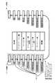
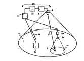
図1にこの発明の第1実施例を示す。この実施例は、自由空間光を用いて形成されたマイクロセル4aないし4dの間を電波を用いて形成されたマクロセル10で補間したセルラネットワークである。この実施例においては、マイクロセルには赤外無線LANを用いた。この赤外無線LANのデータリンク層のプロトコルは、回線争奪方式のプロトコルに分類されるCSMA系のプロトコル(例えば、CSMA/CA、CSMA/CDなど)を採用した。また、マクロセル10としてはPHS−PBX(パーソナルハンディフオン構内電話交換機)を採用した。PHSは周知のように回線交換型の通信方式である。マイクロセル4aないし4dをカバーする基地局は、それぞれ3aないし3dである。基地局3aないし3dは有線網5を介して互いに接続されている。マイクロセル4aないし4dを相互接続する有線網5は10BASE−Tを採用した。この有線網5としてはEthernet系のネットワークを10BASE−Tに限らず採用することができる。有線網5上にはサーバ9aや9bなども接続されている。マクロセル10は基地局6によってカバーされている。基地局6からの電波12はアンテナ8より送信される。
【0033】
赤外無線LANもPHS−PBXも既に商品化され入手することは容易である。赤外無線LANとPHS−PBXの双方を付設すれば、赤外無線LANをマイクロセル、PHS−PBXをマクロセルとしたオーバーレイ型のセルラ通信網が前述のように自然発生することになる。しかしながら、単に赤外無線LANとPHS−PBXのハードウエアを敷設しただけでは、有機的に機能するオーバーレイ型セルラ通信網が構築されたとは言い難いことも前述の通りである。
【0034】
移動局1および2は、電波(PHS)用のインターフェイスと自由空間光(赤外無線LAN)用のインターフエイスの双方を備え、状況に応じてこのふたつのインターフエイスを切り換えて使う。例えば、移動局1はマイクロセル4cのサービスエリア内にいるので、自由空間光インターフエイスを用いて、マイクロセル基地局3cにリンクする。一方、移動局2はマイクロセルのサービスリア内にはいないので、電波を用いてマクロセル基地局6にリンクする。
【0035】
マクロセル基地局6と有線網5とはゲートウェイ7を介して接続されている。したがって、電波によるマクロセル10のネットワークと、自由空間光によるマイクロセル4aないし4dからなるネットワークとは論理的には別のネットワークとして区別されていることになる。これは、マクロセル10として採用したPHSは伝送速度や媒体制御のプロトコルがマイクロセルを司る赤外無線LANと大きくことなるため、物理層に近いところで直結することができないためである。PHSは伝送速度が32Kbps前後であり、データリンク層としては回線交換式のプロトコルを採用している。これに対して赤外無線LANでは、伝送速度は1〜10Mbps前後であり、データリンク層のプロトコルは前述の通りCSMA方式である。このように特性の異なるネットワーク同士を接続するにはネットワーク層以上、すなわちルータ以上で接続する必要がある。したがって、マクロセル基地局6と有線網5とはルータないし、ゲートウェイを介して接続しなくてはならない。
【0036】
基地局3aないし3dと有線網5とはブリッジ13aないし13dを介して接続されている。なお、マイクロセル4aないし4dで採用されている赤外無線LANと有線網5のLANの伝送速度が等しければ、基地局3aないし3dと有線網5とをリピータを介して接続することも不可能ではない。
【0037】
マクロセル10のネットワーク層のプロトコルにはPPP(Point toPoint Protocol)を採用した。このプロトコルの代替としてSLIP(SeriaI Line Internet Protocol)を採用することもできる。マイクロセル4aないし4d及び有線網5のネットワーク層のプロトコルにIP(Internet Protocol)を採用した。
【0038】
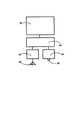
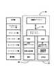
移動局1ないし2は図2に示すような構成を備えている。移動局1ないし2はコンピュータなどの情報処理手段本体20を備えると供に、電波(PHS)用のインターフェイス21、自由空間光(赤外無線LAN)用のインターフェイス22、さらにこのふたつのインターフェイス切換え機構25を備ている。電波(PHS)用のインターフェイス21にはアンテナ23が、自由空間光(赤外無線LAN)用のインターフェイス22にはレンズなどの光学手段24が備えられている。インターフェイス切換え機構25には単なる信号切換え機構のみならず、選択したインターフェイスに対応したプロトコルのスイッチング機構も組み込まれている。前述のように本実施例にあっては、マイクロセルとマクロセルとでは、論理的に別のネットワークであるので、移動局がマクロセル基地局にリンクしている場合と、マイクロセル基地局にリンクしている場合では、IPアドレスが異なることになる。したがって、移動局は一種のルーテイング機構をも有していることになる。
【0039】
また、移動局はネットワーク側(サーバあるいは固定局側)から見るとふたつのIPアドレスを有していることになる。このふたつのIPアドレスは移動局へ至る経路を示すアドレスと見なすことができる。後述のように本発明の特徴のひとつは、経路を示すアドレスと移動局そのものを示すアドレスを別個に設定したことを挙げることができる。なお、経路を示すアドレスは移動局の移動に伴って変化することに注意されたい。
【0040】
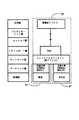
図3には本発明の通信方式に元づく、電波(PHS)用のインターフェイス21、自由空間光(赤外無線LAN)用のインターフェイス22、およびインターフェイス切換え機構25の機能分担を前述のOSI7層モデルにしたがって示した。電波(PHS)用のインターフェイス21にはPHSの物理層とデータリンク層及びネットワーク層の機能26(図3参照)、自由空間光(赤外無線LAN)用のインターフェイス22には赤外無線LAN物理層とデータリンク層及びネットワーク層の機能27(図3参照)をそれぞれ実装した。インターフェイス切換え機構25にはトランスポート層から応用層までの機能28(図3参照)を実装した。機能28においては、情報処理実体20から送られてくる伝送されるべき情報実体にまず応用層レベルのアドレスを含むアプリケーションヘッダを付加してトランスポート層へ送る。トランスポート層ではふたつのネットワークを切り替えるソフトウエア処理を行う。すなわち、PHS側(電波側)のインターフェイス21へパケットを送る場合はPPPに対応するIPアドレスを含むヘッダをパケットに付加し、自由空間光(赤外無線LAN)用のインタ−フェイス22へパケットを送る場合は別のIPアドレスを付加する。なお、自由空間光(赤外無線LAN)用のインターフェイス22のネットワーク層としてはIPに代えてmobile−IPを採用することもできる。mobile−IPは移動するクライアントに対して好適なプロトコルであり、本実施例に採用することによって、より良い制御を行うことができる。
【0041】
電波と赤外光無線LANインターフェイス切り換え機構25のパケットのカプセル組立て及び分解の様子を模式的に示すと図4のようになる。図20との違いは本実施例ではアプリケーションヘッダが応用層で付加されていることである。このアプリケーションヘッダ中に移動局を指し示す応用層レベルのアドレスが記入されている。
【0042】
このようなパケット経路の切り換え機構はルータなどのネットワーク間を接続するための特別のサーバに実装されることはあっても、本実施例のようにクライアント(移動局)側に実装されることはなかった。
【0043】
すなわち、本発明は移動局側にパケット経路の切換え機構、いわゆるルーティング機構を備えることによって、移動局がマイクロセルとマクロセルのどちらにリンクするかを決定している。
【0044】
なお、別の実装として、情報処理手段本体20に図3に示した機能28をすべて実装する方法もあり得る。この方法はハードウエア的には楽になるが、情報処理手段本体20に要求されるソフトウエア的な負担が増大してしまうという欠点もある。
【0045】
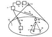
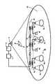
上記に述べた通り、本実施例においては移動局には固有の応用層レベルのアドレスが付与され、ネットワーク層レベルのアドレス(本実施例ではIPアドレス)は経路を指し示すアドレスと見なされる。したがって、図5に示すようにサーバ211から移動局213へのアクセスは応用層レベルのアドレスを基準にして行われる。図5ではサーバ211から移動局213への経路は、ネットワーク212中に参照番号214で示される経路−1と参照番号215で示される経路−2のふたつがある。サーバ211は多くの場合固定局である。サーバ211には経路データベース216が備えられ、この中には例えば、レコードファイル217に示されるような情報が含まれている。レコードファイル217には移動局213の応用層レベルのアドレスに対応するふたつの経路(これは例えばIPアドレスである)が記されている。
【0046】
上記の経路データベースの情報は移動局の移動に伴い、適宜書き換えられる。この書き換えの手順としては公知のmobile−IPやvirtual−IPのプロトコルを用いることが可能である。これらの方法は、いずれも移動局の本籍地を決めておき、移動局は通信が可能な時は現在位置を本籍地宛に通知する仕組みを採用している。ここでいう本籍地とは具体的にはアドレス管理を担うサーバである。ある移動局にアクセスしたいサーバがその移動局の現在位置が不明な場合は、本籍地(すなわちアドレス管理を担うサーバ)へ照会することによっての移動局の現在位置、より正確には、その移動局へ達するための経路情報を取得するのである。
【0047】
図5ではサーバ211が経路管理をしている様子を示しているが、全てのサーバがこのような機構を持つ必要はない。移動局の経路管理を行うサーバを決めておき、他の一般的なサーバはこの経路管理を行うサーバに移動局の経路管理を代行してもらうこともできるからである。このような特定サービスの代行を行う代理サーバ(プロキシサーバ)は当業者には周知の技術である。
【0048】
応用層レベルのアドレスは移動局にユニークなものであれば何でもよい。電子メールアドレスやhttpにおけるURLのような人間が認識しやすいような形態のものであっても良いし、電話番号のような単なるシリアルナンバーであってもよい。応用層レベルのアドレスとして、IPアドレスやイーサネットアドレスの体系を流用することも可能である。IPアドレスやイーサネットアドレスは全世界でユニークなアドレスが決められているからである。ただし、このようなアドレス体系の流用は新規なアドレス体系の設置維持管理が不要という利点はあるものの、ネットワーク内でのルーティングに混乱を来たす危険もあることは注意せねばならない。どちらかと言えば、電子メールアドレスやURLの拡張版として上記の応用層レベルのアドレス体系を定義する方が望ましいと思われる。
【0049】
[第2実施例]
図6にこの発明の第2実施例を示す。図1の第1実施例と異なる点は2点あり、その内のひとつはアンテナ31を備えた無線基地局30が電波を用いた無線LANであることである。具体的には、ISMバンド(lndustry Science Medical周波数帯:日本では2.5GHz帯に割り付けられている)の拡散スペクトル方式の無線LANを用いている。周波数がPHSの1.9GHz帯とはことなるのでアンテナ31はアンテナ6とは異なったものになる。図1の第1実施例と異なるもうひとつの点は、ゲートウェイ7に代えてブリッジ32を採用した点である。
【0050】
ISMバンドの拡散スペクトル方式無線LANはデータリンク層のプロトコルにCSMA/CA方式を採用しており、これはマイクロセル4aないし4dに適用した赤外無線LANに採用されているデータリンク層のプロトコルと同一である。また、有線網5のデータリンク層のプロトコルとして採用したCSMA/CDと極めて近い方式のプロトコルである。
【0051】
本実施例では、第1実施例に比べて、より下層で電波によるマクロセルと自由空間光によるマイクロセルとを接続しているため、ネットワークの構成がハードウエア、ソフトウエア共に簡単になるという利点がある。また、マクロセルとマイクロセル間のパケットの中継は、中継機構にゲートウェイを用いた第1実施例に比べて高速になる、という利点もある。
【0052】
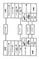
移動局1ないし2は図7に示すような構成を備えている。電波(拡散スペクトル方式無線LAN)用のインターフェイス41、自由空間光(赤外光無線LAN)用のインターフェイス22、さらにこのふたつのインターフェイス切換え機構43を備ている。
【0053】
電波(拡散スペクトル方式無線LAN)用のインターフェイス41には拡散スペクトル方式無線LANの物理層とデータリンク層の機能44(図8参照)、自由空間光(赤外無線LAN)用のインターフヱイス22には赤外無線LAN物理層とデータリンク層の機能27(図8参照)をそれぞれ実装した。インターフェイス切換え機構43にはネットワーク層とトランスポート層までの機能45(図8参照)を実装した。機能45においては、ネットワーク層においてふたつのネットワークを切り替えるソフトウエア処理を行っている。この点が第1実施例の機能28との相違である。
【0054】
本実施例の通信方式は図8に示すように、ネットワーク層においてパケット経路の切り換えを行っていることに特徴がある。図3では経路を指し示すアドレスとして、移動局2がふたつのネットワーク層レベルのアドレス(具体的にはIPアドレス)を有していた。これに対して本実施例では、図8に示すように移動局2はIPアドレスはひとつ有しているだけだが、媒体制御アドレス(MAC:Media Access contorl Address)はMAC−1とMAC−2というふたつのアドレスを有している。この点が第1実施例と本実施例の大きな相違点である。媒体制御アドレスは具体的にはイーサネットアドレスである。本実施例にあっても移動局固有の応用層レベルのアドレスを基準にしてパケットの経路制御が行われることは第1実施例と同様である。
【0055】
また、本実施例では通信経路の管理をネットワーク層レベルで行っているために、トランスポート層にコネクション型のプロトコルであるTCPを採用することが可能となった。TCPは通信相手とコネクションを張ってしまうために、回線が突然切断すると、いわゆるハングアップ状態に陥りやすい。本実施例では、赤外光の通信チャネルが突然切れた場合、ネットワークスイッチャーが電波の通信チャネルへの切り換えを試みるので、ハングアップ状態に陥る危険を低減することができる。TCPはインターネット上の事実上の標準規格であるので、TCPとの互換性が保たれることの利点は大きい。
【0056】
[第3実施例]
図9にこの発明の第3実施例を示す。この実施例では、第1実施例と同様に、マイクロセル4aないし4dは赤外無線LANを、マクロセル10としてPHS−PBX(パーソナルハンデイフオン構内電話交換機)6を用いている。マイクロセルの赤外無線LANとATM−LAN68とはブリッジ13aないし13dを介して接続されている点も第1実施例と同様である。
【0057】
この実施例と第1実施例の異なる点は、マイクロセル4aないし4dおよびサーバ9aないし9bをATM−LANでネットワーク化していることである。具体的には伝送速度25MbpsのATM−25をATM−LANとして採用した。マイクロセル4aないし4dおよびサーバ9aないし9bは、ブリッジ13aないし13dと有線網58を介してATM交換器57に接続されている。すなわち、第1実施例の10BASE−Tで構成された有線網5をATM−LANに置き換えた構成である。なお、有線網42の物理媒体としてはツィストペアケーブルを用いたが、これは光ファイバであっても良い。
【0058】
ATM−LANとPHS−PBX6とはゲートウェイ41を介して接続したが、これはルータないしブリッジに置き換えることも可能である。ATM−LANもPHSもデータリンク層では回線交換のプロトコルに従っているので、原理的にはデータリンク層での接続が不可能ではないからである。ただし、実装上は、ATM−LANとPHSの伝送速度が大きくことなるためにデータリンク層での接続には困難な面もある。
【0059】
本実施例では、マイクロセルを通さない場合は、伝送路全体にわたって伝送容量の予約(Reservation)が可能である。前述の通り、ATM−LANもPHSもデータリンク層で回線交換のプロトコルに従っているからである。このため、リアルタイム性の要求される信号(音声や映像)はマイクロセルを通さない方が信号の連続性の確保には都合が良い。以上から、リアルタイム性の要求される信号(音声や映像)の伝送は、端末がマイクロセル内に居る場合でもマクロセル経由で行うという制御手順が考えられる(図10および図11参照)。
【0060】
図10は通常のデータ通信の場合のルートである。マイクロセル4a内に移動局1がある場合、移動局1とサーバ9aの間でやりとりされる、リアルタイム性を要求されない通常のデータ通信パケットは赤外無線LAN基地局3a、ブリッジ13a、ATM交換器57を経て交信される。図10のルート50、51、52の経路を経て移動局1とサーバ9aの間でリアルタイム性を要求されない通常のデータ通信パケットが送受信されるわけである。
【0061】
図11はリアルタイム性を要求される信号(音声、映像など)の場合のルートである。マイクロセル4a内に移動局1がある場合、移動局1とサーバ9aの間でやりとりされる、リアルタイム性を要求される信号は、PHS交換器6、ゲートウェイ56、ATM交換器57を経て交信される。図11のルート53、54、55の経路を経て移動局1とサーバ9aの間でリアルタイム性を要求される信号が送受信されるわけである。
【0062】
移動局1は図12に示すような構成を備えている。これはほとんど図2の構成と同様であるが、インターフェイス切換え機構60の構造が第1実施例の場合とは異なる。この相違点は主にソフトウエア的なものである。
【0063】
図13には、本実施例における通信方式に元づく、電波(PHS)用のインターフェイス21、自由空間光(赤外無線LAN)用のインターフェイス22、およびインターフェイス切換え機構60の機能分担を前述のOSI7層モデルにしたがって示した。電波(PHS)用のインターフェイス21の機能26と自由空間光(赤外無線LAN)用のインターフェイス22の機能27は図3の場合と同様である。図3と異なるのは、インターフェイス切換え機構60の機能61である。機能61においてはセッション層においてふたつのネットワークを切り替えるソフトウエア処理を行っている。また、自由空間光(赤外無線LAN)チャネル側のトランスポート層としてはUDPを採用した。UDPはコネクションレス型のプロトコルである点がTCPと異なる。
【0064】
本実施例にあっても、第1実施例と同様に移動局はふたつのネットワーク層レベルのアドレス(具体的にはIPアドレス)を有することになる。また、セッション層レベルでセッションを識別するヘッダは当然二通り存在することになる。異なるセッションを識別する識別子(ヘッダなど)は通常アドレスとは言わず、セッション名という呼び方をする。これは従来のインターネットワーキングでは、ネットワーク間の相互接続はトランスポート層レベルで吸収されていることを前提としていたからである。
【0065】
このようにしたのは、データ通信用のパケットのみを通信を行う場合と、リアルタイム性の要求される音声や映像などの信号をふくむ通信を行う場合は、通信のセッションを切り換える必要があるからである。トランスポート層以下ではパケットの中身(データ通信パケットか音声パケットか)に応じてルートを変える機能は一般に実装されない。したがって、より上層のセッション層でルート選択を行う必要が生じるのである。
【0066】
上記構成の結果、リアルタイム性の要求される音声や映像は、リアルタイム性の保証される伝送路を経由して伝送されることになり、通信のサービスの質が向上することになる。
【0067】
移動局の移動が生じた場合、マイクロセル(自由空間光)を経由した伝送チャネルの方が切断の危険性が高い。このため、本実施例にあっては自由空間光の伝送チャネル側にはトランスポート層としてコネクションレス型のUDPを採用した。UDPは回線の切断によって、いわゆるハングアツプが生じる危険がTCPに比べて低いという利点がある。
【0068】
なお、図13では、セッション層でネットワーク切り換えを行うとしたが、さらに上層において切り換えを行うことを否定するものではないことを付け加えておく。リアルタイム性のある信号と無い信号とを、図12のネットワーク構成において混在させる場合は、セッション層以上でのネットワーク切り換えが必要になるというのが図13の実装方法の趣旨である。
【0069】
また、伝送チャネルが自由空間光と電波のふたつの場合について述べたが、この発明の通信方式に限れば、さらに多数の伝送チャネルがある場合に拡張され得ることは当業者にとって自明である。ネットワークスイッチャ、トランスポートスイッチャ、セッションスイッチャの下に二つではなく三つあるいはさらに多数の経路を実装すれば良いのである。
【0070】
移動局が3つ以上の伝送チャネルを備えている場合は、当然のことながら経路を示すアドレスも3つ以上存在することになる。3つ以上の伝送チャネルを備えている移動局は媒体制御アドレスやIPアドレスを3つ以上有することになる。
【0071】
[第4実施例]
図14にこの発明の第4実施例を示す。本実施例の特徴はマイクロセル間を接続する有線網15としてカップルドスターネットワークを採用したことである。カップルドスターネットワーク15は、相互接続可能なスターカプラ16同士を双方向性光中継増幅装置17を介して接続した構造である。カップルドスターネットワークについては、特開平5−3457(米国特許5,282,257)及び、論文Takeshi Ota:’Coupled starnetwork:a new configration for optical local area network’,IEICE Trans.Commun.,1992,E75B,pp67−75参照。
【0072】
カップルドスターネットワークと自由空間光伝送とは物理層での接続が可能である。したがって、第1ないし第2実施例において用いていたブリッジ13が不要となり、ネットワーク構成が簡単になる。
【0073】
この発明の第4実施例においては、第1実施例に準じて、図2ないし図3に示したような移動局1ないし2の構造を採用することができる。あるいは、第2実施例に準じて、図7ないし図8に示したような移動局1ないし2の構造を採用することができる。
【0074】
【発明の効果】
以上、この発明のセルラ通信網によれば要所のみを自由空間光を用いた高速伝送可能なマイクロセルとして構成し、ぞの他の広い領域を低速の電波を用いたマクロセルとして構成するので、自由空間光を用いたマイクロセル用基地局の設置箇所を最小限にすることができる。
【0075】
この発明の通信方式によれば、移動局の側にパケット経路選択の機能を付加することができ、その結果、通信の信頼性の向上、通信のサービスの質の向上が実現できる。
【図面の簡単な説明】
【図1】この発明の第1実施例を示す概略図である。
【図2】図1の移動局1ないし2の構造を示す概略図である。
【図3】図2に示した各構成要素の機能分担を示す概略図である。
【図4】この発明におけるパケットの組立てと分解の様子を示す概略図である。
【図5】この発明におけるサーバから移動局へのアクセスの様子を示す概略図である。
【図6】この発明の第2実施例を示す概略図である。
【図7】図6の移動局1ないし2の構造を示す概略図である。
【図8】図7に示した各構成要素の機能分担を示す概略図である。
【図9】この発明の第3実施例を示す概略図である。
【図10】図9において通常のデータ通信の場合のルートを示す概略図である。
【図11】図9においてリアルタイム性を要求される信号(音声、映像など)のルートを示す概略図である。
【図12】図9の移動局1の構造を示す概略図である。
【図13】図12に示した各構成要素の機能分担を示す概略図である。
【図14】この発明の第4実施例を示す概略図である。
【図15】従来のセルラ通信網を示す概略図である。
【図16】従来提案されているオーバーレイ型セルラの概略を示す図である。
【図17】従来技術(特開平2−162846)を示す概略図である。
【図18】ふたつのネットワークを中継手段により接続した構造を示す概略図である。
【図19】OSI7層モデルにおける、ゲートウェイ、ルータ、ブリッジ、リピータの対応図である。
【図20】OSI7層モデルにおける、パケットの組立て分解の様子を模式的に示す機略図である。
【符号の説明】
1〜2 移動局
3a〜3d 基地局
4a〜4d マイクロセル
5 有線網
6 マクロセル基地局
8 アンテナ
10 マクロセル
12 基地局6からの電波
13a〜13d ブリツジ
15 有線網(カップルドスターネットワーク)
16 相互接続可能なスターカプラ
17 双方向性光中継増幅器
20 情報処理手段本体
21 電波(PHS)用のインターフェイス
22 自由空間光(赤外無線LAN)用のインターフェイス
23 アンテナ
24 レンズなどの光学手段
25 電波と赤外光無線LANインターフェイス切換え機構
26 PHSの物理層とデータリンク層及びネットワーク層の機能
27 赤外無線LAN物理層とデータリンク層及びネットワーク層の機能28 インターフェイス切換え機構25の応用層からネットワーク層とトランスポート層までの機能
30 ISMバンドの拡散スペクトル方式の無線LANの無線基地局
31 アンテナ
41 電波(拡散スペクトル方式無線LAN)用のインターフェイス
42 アンテナ
43 インターフェイス切換え機構
44 拡散スペクトル方式無線LANの物理層とデータリンク層の機能
45 インターフェイス切換え機構43の応用層からネットワーク層とトランスポート層までの機能
50、51、52 リアルタイム性を要求されない通常のデータ通信パケットのルート
53、54、55 リアルタイム性を要求される信号のルート
56 ゲートウェイ
57 ATM交換器
58 ATM−LAN
60 インターフェイス切換え機構
61 インターフェイス切換え機構60の機能
101a〜101d 基地局
102a 移動局
103a〜103d セル
111 リモコン
112〜113 中継器
114 制御対象機器
123 自由空間光
124 電波
116〜117 アンテナ
119 アンテナ
115 中継器112の光インターフェイス
121 リモコン111のある部屋
122 制御対象機器114のある部屋
120 部屋121と部屋122とを隔てる壁
130 中継手段(ゲートウェイ、ルータ、ブリッジ、リピータなど)
131〜132 ネットワーク
201 通信衛星
202 通信衛星によって形成されたマクロセル
203 通信衛星との交信に用いられる電波
204 地上に設けられた基地局との交信に用いられる電波
211 サーバ(固定局)
212 通信ネットワーク
213 移動局
214 サーバ211から移動局213に達する第1の経路
215 サーバ211から移動局213に達する第2の経路
216 サーバ211内に設けられた経路データベース
217 経路データベース216内のレコードファイル[0001]
BACKGROUND OF THE INVENTION
The present invention relates to a cellular communication network and a communication method therefor, and more particularly to an overlay type cellular communication network having a structure in which cells having different cell sizes overlap each other and a communication method therefor. The present invention also relates to a cellular communication network using both free space light and radio waves as transmission media. The present invention also relates to a wide area communication network and a local area network (LAN). The present invention also relates to a routing technique that is a method of switching a transmission path of a packet that carries information transmission.
[0002]
[Prior art]
Conventionally, a cellular communication network as shown in FIG. 15 is widely known. The
[0003]
As a developed form of the cellular communication network as described above, a cellular communication network in which a macro cell which is a large size cell and a micro cell which is a small size cell are integrated has been proposed. For example, as shown in FIG. 16, a method is proposed in which a
[0004]
Such a structure in which macro cells and micro cells overlap is hereinafter referred to as an overlay type cellular communication network. Actually, such an overlay type cellular communication network is born spontaneously. For example, if a PHS network with a cell size of about several hundred meters is attached to an existing area of a mobile telephone network with a cell size of about several kilometers, it can be said formally as an overlay type cellular communication network. However, at present, it is difficult to say that these communication networks are operated as separate communication networks and are organically integrated as a communication network. That is, the interconnection between the macro cell and the micro cell is not considered.
[0005]
In addition, as a cellular communication network as described above, a method has been proposed in which an optical fiber network is used as a wired network between base stations, and signal distribution between base stations is performed using an optical signal directly modulated with radio waves (specialty). No. 6-311083, or Arai et al., “Experimental Study of Dynamic Range in Wireless Microcell System Using Optical Fiber”, 1994 IEICE Spring Conference B-448 (1994)). In configuring this cellular network, a system using free space light for communication between a base station and a mobile station has been proposed (see Japanese Patent Laid-Open No. 3-91329). Further, although not a cellular network, there has been proposed a system for distributing an optical signal directly modulated with radio waves in a local communication system using an optical fiber network (see Japanese Patent Laid-Open No. 6-164498).
[0006]
On the other hand, a system that combines light and radio waves in a remote control system has been proposed (see Japanese Patent Laid-Open No. 2-162846). This is a system for remotely controlling a device that is not within the line-of-sight distance, as shown in FIG. A control signal from the
[0007]
In another example of a remote control system, a signal from a mobile station to a base station (repeater) uses radio waves, and a signal from the base station (repeater) to a mobile station uses free space light. It has been proposed (see JP-A-2-235447).
[0008]
FIG. 18 shows a network (internetwork) having a structure in which two
[0009]
FIG. 20 schematically shows how packets are assembled and disassembled in the OSI 7-layer model. On the sending side, packets are sequentially transmitted from the upper layer to the lower layer of the OSI7 layer model, and various headers (session header, transport header, network header, data link header) are added corresponding to each layer. To go. On the receiving side, the next packet is transmitted from the lower layer to the upper layer of the
[0010]
Although omitted in FIG. 20, a trailer corresponding to a header may be provided at the rear of the packet. Various trailers (session trailer, transport trailer, network trailer, data link trailer) are added corresponding to various headers (session header, transport header, network header, data link header). Data entities are encapsulated at each layer, sandwiched between headers and trailers. Although the header is essential, the trailer is omitted in FIG. 20 because it may be omitted in some cases.
[0011]
By the way, since light is an electromagnetic wave having a very high frequency, it is possible to carry a broadband modulation signal by using light as a carrier. However, there is a drawback that light is easily blocked by an object. For this reason, when a cellular network is formed using free space light, there is a drawback that one cell becomes small. In other words, a large number of cells are required to cover the same area.
[0012]
In the remote control system, there has been proposed a system for interpolating the limit of the reach of free space light by using radio waves and light (Japanese Patent Laid-Open No. 2-162846 described above). However, it is only insufficient to replace a specific signal path with radio waves, and from the viewpoint of covering a wide range of a certain extent like a cellular network without omission.
[0013]
In a general cellular network, the above-described communication procedure called handover is a control procedure performed between a plurality of base stations and mobile stations. There was also a problem of having to have information processing capabilities such as management.
[0014]
[Problems to be solved by the invention]
The present invention has been made in view of the above circumstances, and an object thereof is to provide a novel overlay type cellular communication network in which radio waves and free space light are integrated. In addition, not only the intentionally designed overlay type cellular communication network but also the overall overlay type cellular communication network including the naturally occurring overlay type cellular communication network as described above, the interconnection of macrocells and microcells The object is to realize efficient communication by providing a communication method that enables it. Two technical problems arise for the method of interconnecting the macrocell and the microcell in the overlay type cellular communication network. One is how to determine whether the mobile station is linked to the micro cell or the macro cell, and the other is an access method from the fixed station side to the mobile station.
[0015]
[Means for Solving the Problems]
According to the present invention, in order to achieve the above object, a cellular communication network includes a free space optical interface, a radio wave interface, a mobile station including the free space optical interface and the radio wave interface switching mechanism, A fixed first base station that performs communication using the free space light with the mobile station in the first area and a communication that uses radio waves with the mobile station in the second area. The second base station is provided.
[0016]
According to this configuration, in the second region (macrocell) formed by radio waves, it is possible to reliably perform communication while suppressing the problem of obstacles in a wide range, and the first region (microcell) formed by free space light. (Cell) can perform high-speed communication. If the micro cell is included in the macro cell, the micro cell can be arranged at a necessary place so that sufficiently high-speed communication can be used, and a less important area can be covered by the macro cell communication.
[0017]
In addition, the link to the macro cell and the link to the micro cell of the mobile station can be switched as well as a multiplexed link. As a result, it is possible to increase communication capacity and improve reliability due to an increase in communication opportunities as seen from the mobile station.
[0018]
Also, in this configuration, a line contention type protocol is adopted as the data link layer communication method defined in the
[0019]
Further, a line contention type protocol is adopted as a data link layer communication method defined in the
[0020]
The cellular network is further provided with a wired communication network for connecting the first base stations, and the wired communication network uses a circuit switching type protocol as a data link layer communication method defined by the
[0021]
According to the present invention, in order to achieve the above-mentioned object, the first cellular communication network composed of cells having at least the first cell size overlaps the second cellular communication network composed of the second cell size. In the overlay type cellular communication network formed in this manner, the mobile stations belonging to the overlay type cellular communication network have a mobile station identification address at the application layer level defined in the OSI7 layer model as an address unique to the mobile station, and The address belongs to the data link layer, the network layer, the transport layer, the session layer, and the presentation layer defined by the
[0022]
The server provided as a fixed station in the overlay type cellular communication network has a route database related to the mobile station, and the record file in the route database includes at least one mobile station identification address and the mobile station identification. And a plurality of route addresses reaching the mobile station corresponding to the address.
[0023]
According to the present invention, in order to achieve the above object, in the communication method of the above cellular communication network, the mobile station controls at least the physical layer and the data link layer among the layers defined by the
[0024]
According to the present invention, in order to achieve the above object, in the communication method of the above cellular communication network, the mobile station performs control procedures for the physical layer, data link layer, and network layer defined by the
[0025]
According to the present invention, in order to achieve the above object, in the communication method of the above cellular communication network, the mobile station has a physical layer, a data link layer, a network layer, and a transport defined by the
[0026]
According to the present invention, in order to achieve the above object, in the communication method of the cellular communication network, the mobile station includes a physical layer defined by an
[0027]
According to the present invention, in order to achieve the above-mentioned object, the first cellular communication network composed of cells having at least the first cell size and the second cellular communication network composed of the second cell size are overlapped. In the communication method used for the formed overlay type cellular communication network, a mobile station belonging to the overlay type cellular communication network has an application layer level mobile station identification address defined by the
[0028]
Further, according to the present invention, in the process of assembling a packet to transmit information, an application layer header including the mobile station identification address defined in the application layer is first added to the data entity to be transmitted at the head of the data entity. Subsequently, a process of assembling so that a header below the presentation layer defined in the OSI7 layer model is sequentially added to the head portion of the packet is included.
[0029]
According to the present invention, the server provided as a fixed station in the overlay type cellular communication network has a mobile station route database, and the record file in the route database includes at least one mobile station identification address, And a plurality of route addresses reaching the mobile station corresponding to the mobile station identification address.
[0030]
Further, according to the present invention, in order to achieve the above object, the mobile station for the cellular network is provided with a free space optical interface, a radio wave interface, and a switching mechanism for the free space optical interface and the radio wave interface. ing.
[0031]
According to the present invention, in order to achieve the above object, a mobile station for a cellular communication network has an application layer level mobile station identification address defined in the OSI7 layer model as a mobile station specific address, , Addresses belonging to the data link layer, the network layer, the transport layer, the session layer, and the presentation layer defined by the OSI layer model, and having two or more addresses indicating paths that can reach the mobile station.
[0032]
BEST MODE FOR CARRYING OUT THE INVENTION
Examples of the present invention will be described below.
[First embodiment]
FIG. 1 shows a first embodiment of the present invention. This embodiment is a cellular network obtained by interpolating between the
[0033]
Both the infrared wireless LAN and the PHS-PBX are easily commercialized and available. If both the infrared wireless LAN and the PHS-PBX are attached, an overlay type cellular communication network using the infrared wireless LAN as a micro cell and the PHS-PBX as a macro cell will naturally occur as described above. However, as described above, it is difficult to say that an overlay-type cellular communication network that functions organically is constructed simply by installing infrared wireless LAN and PHS-PBX hardware.
[0034]
The
[0035]
The macro
[0036]
The
[0037]
PPP (Point to Point Protocol) is adopted as the network layer protocol of the
[0038]
The
[0039]
Further, the mobile station has two IP addresses when viewed from the network side (server or fixed station side). These two IP addresses can be regarded as addresses indicating routes to the mobile station. As will be described later, one of the features of the present invention is that the address indicating the route and the address indicating the mobile station itself are set separately. It should be noted that the address indicating the route changes as the mobile station moves.
[0040]
FIG. 3 shows the above-mentioned OSI 7-layer model showing the function sharing of the radio wave (PHS)
[0041]
FIG. 4 schematically shows the capsule assembly and disassembly of the radio wave and infrared wireless LAN
[0042]
Although such a packet path switching mechanism may be implemented on a special server for connecting between networks such as routers, it may not be implemented on the client (mobile station) side as in this embodiment. There wasn't.
[0043]
That is, according to the present invention, a mobile station side is provided with a packet path switching mechanism, that is, a so-called routing mechanism, thereby determining whether the mobile station is linked to a micro cell or a macro cell.
[0044]
As another implementation, there may be a method of mounting all the
[0045]
As described above, in this embodiment, a unique application layer level address is given to the mobile station, and the network layer level address (IP address in this embodiment) is regarded as an address indicating a route. Therefore, as shown in FIG. 5, the access from the
[0046]
The information in the route database is appropriately rewritten as the mobile station moves. As the rewriting procedure, a known mobile-IP or virtual-IP protocol can be used. Each of these methods employs a system in which the mobile station's permanent address is determined and the mobile station notifies the current address to the registered address when communication is possible. The permanent address here is specifically a server responsible for address management. If a server that wants to access a certain mobile station does not know the current location of the mobile station, the current location of the mobile station by inquiring to the domicile (that is, the server responsible for address management), more precisely, the mobile station The route information to reach is obtained.
[0047]
Although FIG. 5 shows a state in which the
[0048]
The application layer level address may be anything as long as it is unique to the mobile station. It may be in a form that is easy for humans to recognize, such as an e-mail address or URL in http, or may be a simple serial number such as a telephone number. It is also possible to divert the IP address or Ethernet address system as the application layer level address. This is because IP addresses and Ethernet addresses are determined to be unique worldwide. However, it should be noted that the diversion of such an address system has the advantage of not requiring the installation and maintenance of a new address system, but there is also a risk of confusion in routing within the network. If anything, it would be more desirable to define the above application layer level address system as an extended version of an email address or URL.
[0049]
[Second Embodiment]
FIG. 6 shows a second embodiment of the present invention. There are two differences from the first embodiment of FIG. 1, and one of them is that the
[0050]
The ISM band spread spectrum wireless LAN adopts the CSMA / CA method as the data link layer protocol, which is the data link layer protocol adopted for the infrared wireless LAN applied to the
[0051]
In this embodiment, compared with the first embodiment, since the macro cell using radio waves and the micro cell using free space light are connected in the lower layer, there is an advantage that the configuration of the network is simple for both hardware and software. is there. In addition, the packet relay between the macro cell and the micro cell has an advantage that it is faster than the first embodiment using a gateway as a relay mechanism.
[0052]
The
[0053]
The radio wave (spread spectrum wireless LAN) interface 41 includes a spread spectrum wireless LAN physical layer and data link layer function 44 (see FIG. 8), and a free space light (infrared wireless LAN)
[0054]
As shown in FIG. 8, the communication system of this embodiment is characterized in that the packet path is switched in the network layer. In FIG. 3, the
[0055]
In this embodiment, since communication paths are managed at the network layer level, it is possible to adopt TCP, which is a connection type protocol, in the transport layer. Since TCP establishes a connection with a communication partner, if the line is suddenly disconnected, it is easy to fall into a so-called hang-up state. In this embodiment, when the infrared communication channel is suddenly cut, the network switcher attempts to switch to the radio communication channel, so that the risk of falling into a hang-up state can be reduced. Since TCP is a de facto standard on the Internet, the advantage of maintaining compatibility with TCP is great.
[0056]
[Third embodiment]
FIG. 9 shows a third embodiment of the present invention. In this embodiment, as in the first embodiment, the
[0057]
The difference between this embodiment and the first embodiment is that the
[0058]
Although the ATM-LAN and the PHS-
[0059]
In this embodiment, when the microcell is not passed, it is possible to reserve the transmission capacity over the entire transmission line. This is because, as described above, both ATM-LAN and PHS follow the circuit switching protocol in the data link layer. For this reason, it is more convenient for ensuring signal continuity that signals (audio and video) that require real-time characteristics do not pass through the microcells. From the above, it is conceivable that the control procedure is such that transmission of signals (audio and video) that require real-time performance is performed via the macro cell even when the terminal is in the micro cell (see FIGS. 10 and 11).
[0060]
FIG. 10 shows a route for normal data communication. When the
[0061]
FIG. 11 shows a route in the case of a signal (audio, video, etc.) that requires real-time performance. When the
[0062]
The
[0063]
FIG. 13 shows the function sharing of the radio wave (PHS)
[0064]
In this embodiment, the mobile station has two network layer level addresses (specifically, IP addresses) as in the first embodiment. There are naturally two types of headers for identifying a session at the session layer level. An identifier (such as a header) for identifying a different session is not called an ordinary address but is called a session name. This is because conventional internetworking presupposes that interconnections between networks are absorbed at the transport layer level.
[0065]
This is because it is necessary to switch between communication sessions when communicating only data communication packets and when communication including signals such as audio and video that require real-time performance. is there. Below the transport layer, the function of changing the route according to the contents of a packet (data communication packet or voice packet) is generally not implemented. Therefore, it is necessary to perform route selection at a higher session layer.
[0066]
As a result of the above configuration, audio and video that require real-time performance are transmitted via a transmission path that guarantees real-time performance, and the quality of communication service is improved.
[0067]
When the mobile station moves, the transmission channel via the microcell (free space light) has a higher risk of disconnection. Therefore, in this embodiment, a connectionless type UDP is adopted as a transport layer on the free space light transmission channel side. UDP has the advantage that the risk of so-called hang-up due to line disconnection is lower than that of TCP.
[0068]
In FIG. 13, it is assumed that network switching is performed in the session layer, but it is added that it is not denied that switching is performed in the upper layer. The purpose of the mounting method of FIG. 13 is that when a signal having real-time characteristics and a signal having no real time are mixed in the network configuration of FIG. 12, network switching at the session layer or higher is required.
[0069]
Further, although the case where the transmission channel is two of free space light and radio wave has been described, it is obvious to those skilled in the art that the present invention can be extended when there are a large number of transmission channels as far as the communication system of the present invention is limited. Instead of two under the network switcher, transport switcher and session switcher, three or even more routes may be implemented.
[0070]
When the mobile station has three or more transmission channels, there are naturally three or more addresses indicating routes. A mobile station equipped with three or more transmission channels has three or more medium control addresses and IP addresses.
[0071]
[Fourth embodiment]
FIG. 14 shows a fourth embodiment of the present invention. The feature of this embodiment is that a coupled star network is adopted as the
[0072]
The coupled star network and free space optical transmission can be connected in the physical layer. Therefore, the bridge 13 used in the first and second embodiments is not necessary, and the network configuration is simplified.
[0073]
In the fourth embodiment of the present invention, the structure of the
[0074]
【The invention's effect】
As described above, according to the cellular communication network of the present invention, only the main points are configured as microcells capable of high-speed transmission using free space light, and other wide areas are configured as macrocells using low-speed radio waves. The installation location of the base station for microcells using free space light can be minimized.
[0075]
According to the communication system of the present invention, a packet route selection function can be added to the mobile station side, and as a result, communication reliability and communication service quality can be improved.
[Brief description of the drawings]
FIG. 1 is a schematic view showing a first embodiment of the present invention.
FIG. 2 is a schematic diagram showing the structure of
FIG. 3 is a schematic diagram showing the function sharing of each component shown in FIG. 2;
FIG. 4 is a schematic diagram showing how packets are assembled and disassembled in the present invention.
FIG. 5 is a schematic diagram showing a state of access from a server to a mobile station in the present invention.
FIG. 6 is a schematic view showing a second embodiment of the present invention.
7 is a schematic diagram showing the structure of
FIG. 8 is a schematic diagram showing the functional sharing of each component shown in FIG. 7;
FIG. 9 is a schematic view showing a third embodiment of the present invention.
10 is a schematic diagram showing a route in the case of normal data communication in FIG. 9. FIG.
11 is a schematic diagram showing a route of signals (audio, video, etc.) required to have real-time characteristics in FIG. 9;
12 is a schematic diagram showing the structure of the
13 is a schematic diagram showing the function sharing of each component shown in FIG. 12;
FIG. 14 is a schematic view showing a fourth embodiment of the present invention.
FIG. 15 is a schematic diagram showing a conventional cellular communication network.
FIG. 16 is a diagram showing an outline of a conventionally proposed overlay type cellular.
FIG. 17 is a schematic view showing a conventional technique (Japanese Patent Laid-Open No. 2-162846).
FIG. 18 is a schematic diagram showing a structure in which two networks are connected by relay means.
FIG. 19 is a correspondence diagram of gateways, routers, bridges, and repeaters in the
FIG. 20 is a schematic diagram schematically showing how packets are assembled and disassembled in the OSI 7-layer model.
[Explanation of symbols]
1-2 mobile station
3a-3d base station
4a-4d microcell
5 Wired network
6 Macrocell base station
8 Antenna
10 Macrocell
12 Radio waves from
13a-13d Bridge
15 Wired network (coupled star network)
16 interconnectable star couplers
17 Bidirectional optical repeater amplifier
20 Information processing means body
21 Interface for radio wave (PHS)
22 Interface for free space light (infrared wireless LAN)
23 Antenna
24 Optical means such as lenses
25 Radio and infrared wireless LAN interface switching mechanism
26 Functions of PHS physical layer, data link layer and network layer
27 Infrared wireless LAN physical layer, data link layer and network layer functions 28
30 ISM band spread spectrum wireless LAN base station
31 Antenna
41 Interface for radio waves (spread spectrum wireless LAN)
42 Antenna
43 Interface switching mechanism
44 Functions of physical layer and data link layer of spread spectrum wireless LAN
45 Functions from application layer to network layer and transport layer of
50, 51, 52 Normal data communication packet route that does not require real-time performance
53, 54, 55 Routes of signals that require real-time performance
56 gateways
57 ATM switch
58 ATM-LAN
60 Interface switching mechanism
61 Functions of the
101a to 101d base station
102a mobile station
103a-103d cells
111 remote control
112-113 repeater
114 Controlled equipment
123 Free space light
124 radio wave
116-117 antenna
119 antenna
115 Optical interface of
121 Room with
122 Room with controlled
120
130 Relay means (gateway, router, bridge, repeater, etc.)
131-132 network
201 Communication satellite
202 Macrocell formed by communication satellite
203 Radio waves used for communication with communication satellites
204 Radio waves used for communication with base stations installed on the ground
211 server (fixed station)
212 Communication network
213 Mobile station
214 First route from the
215 Second route from the
216 Route database provided in the
217 Record file in the
Claims (15)
Translated fromJapanese第1の領域において、上記第1のアドレスに基づく経路を介して上記移動局との間で自由空間光を用いた通信を行う固定された第1の基地局と、
第2の領域において、上記第2のアドレスに基づく経路を介して上記移動局との間で電波を用いた通信を行う固定された第2の基地局とを有することを特徴とするセルラ通信網。A free space optical interface; a radio wave interface; and a switching mechanism between the free space optical interface and the radio interface, and a mobile station identification address and a first routing instruction address applied to communication via the free space optical interface. A mobile station having a first address and a second address as a route instruction address applied to communication via the radio wave interface, and performing communication by selective application of the two route instruction addresses;
In a first region, a fixed first base station that performs communication using free space light with the mobile station via a path based on the first address;
A cellular communication network comprising: a fixed second base station that performs radio wave communication with the mobile station via a path based on the second address in the second area .
Priority Applications (2)
| Application Number | Priority Date | Filing Date | Title |
|---|---|---|---|
| JP02626397AJP3832006B2 (en) | 1996-02-26 | 1997-02-10 | Cellular communication network and communication method thereof |
| US08/810,112US6115615A (en) | 1996-02-26 | 1997-02-25 | Cellular communication network and its communication method |
Applications Claiming Priority (3)
| Application Number | Priority Date | Filing Date | Title |
|---|---|---|---|
| JP3760196 | 1996-02-26 | ||
| JP8-37601 | 1996-02-26 | ||
| JP02626397AJP3832006B2 (en) | 1996-02-26 | 1997-02-10 | Cellular communication network and communication method thereof |
Publications (2)
| Publication Number | Publication Date |
|---|---|
| JPH09294290A JPH09294290A (en) | 1997-11-11 |
| JP3832006B2true JP3832006B2 (en) | 2006-10-11 |
Family
ID=26364014
Family Applications (1)
| Application Number | Title | Priority Date | Filing Date |
|---|---|---|---|
| JP02626397AExpired - LifetimeJP3832006B2 (en) | 1996-02-26 | 1997-02-10 | Cellular communication network and communication method thereof |
Country Status (2)
| Country | Link |
|---|---|
| US (1) | US6115615A (en) |
| JP (1) | JP3832006B2 (en) |
Families Citing this family (68)
| Publication number | Priority date | Publication date | Assignee | Title |
|---|---|---|---|---|
| US6169789B1 (en)* | 1996-12-16 | 2001-01-02 | Sanjay K. Rao | Intelligent keyboard system |
| US6405049B2 (en)* | 1997-08-05 | 2002-06-11 | Symbol Technologies, Inc. | Portable data terminal and cradle |
| US6757746B2 (en) | 1997-10-14 | 2004-06-29 | Alacritech, Inc. | Obtaining a destination address so that a network interface device can write network data without headers directly into host memory |
| US6697868B2 (en) | 2000-02-28 | 2004-02-24 | Alacritech, Inc. | Protocol processing stack for use with intelligent network interface device |
| US7167927B2 (en) | 1997-10-14 | 2007-01-23 | Alacritech, Inc. | TCP/IP offload device with fast-path TCP ACK generating and transmitting mechanism |
| US7174393B2 (en) | 2000-12-26 | 2007-02-06 | Alacritech, Inc. | TCP/IP offload network interface device |
| US7185266B2 (en) | 2003-02-12 | 2007-02-27 | Alacritech, Inc. | Network interface device for error detection using partial CRCS of variable length message portions |
| US7133940B2 (en) | 1997-10-14 | 2006-11-07 | Alacritech, Inc. | Network interface device employing a DMA command queue |
| US6226680B1 (en) | 1997-10-14 | 2001-05-01 | Alacritech, Inc. | Intelligent network interface system method for protocol processing |
| US8782199B2 (en) | 1997-10-14 | 2014-07-15 | A-Tech Llc | Parsing a packet header |
| US8621101B1 (en) | 2000-09-29 | 2013-12-31 | Alacritech, Inc. | Intelligent network storage interface device |
| US7237036B2 (en) | 1997-10-14 | 2007-06-26 | Alacritech, Inc. | Fast-path apparatus for receiving data corresponding a TCP connection |
| US6687758B2 (en) | 2001-03-07 | 2004-02-03 | Alacritech, Inc. | Port aggregation for network connections that are offloaded to network interface devices |
| US6658480B2 (en) | 1997-10-14 | 2003-12-02 | Alacritech, Inc. | Intelligent network interface system and method for accelerated protocol processing |
| US8539112B2 (en) | 1997-10-14 | 2013-09-17 | Alacritech, Inc. | TCP/IP offload device |
| US6434620B1 (en) | 1998-08-27 | 2002-08-13 | Alacritech, Inc. | TCP/IP offload network interface device |
| JP3763197B2 (en)* | 1997-12-12 | 2006-04-05 | ソニー株式会社 | Information processing system, information processing apparatus, information processing method, and recording medium |
| FI106511B (en)* | 1998-02-10 | 2001-02-15 | Nokia Networks Oy | Reduction of signaling load in a packet radio network |
| KR100285887B1 (en)* | 1998-06-27 | 2001-04-16 | 김대기 | Subway and building internal service system by dedicated channel in CDMA mobile phone system |
| US7664883B2 (en) | 1998-08-28 | 2010-02-16 | Alacritech, Inc. | Network interface device that fast-path processes solicited session layer read commands |
| DE69933542T2 (en)* | 1999-05-26 | 2007-05-16 | Sony Deutschland Gmbh | Geolocation determination |
| US6526034B1 (en) | 1999-09-21 | 2003-02-25 | Tantivy Communications, Inc. | Dual mode subscriber unit for short range, high rate and long range, lower rate data communications |
| IL136207A0 (en)* | 2000-05-17 | 2001-05-20 | Naftel Technologies Ltd | An e-mail management system for wireless pcd |
| JP3732389B2 (en)* | 2000-06-16 | 2006-01-05 | 松下電器産業株式会社 | Wireless communication system, base station device, communication terminal device, and wireless communication method |
| US7630721B2 (en) | 2000-06-27 | 2009-12-08 | Ortiz & Associates Consulting, Llc | Systems, methods and apparatuses for brokering data between wireless devices and data rendering devices |
| US7812856B2 (en) | 2000-10-26 | 2010-10-12 | Front Row Technologies, Llc | Providing multiple perspectives of a venue activity to electronic wireless hand held devices |
| US7149549B1 (en) | 2000-10-26 | 2006-12-12 | Ortiz Luis M | Providing multiple perspectives for a venue activity through an electronic hand held device |
| US7146636B2 (en)* | 2000-07-24 | 2006-12-05 | Bluesocket, Inc. | Method and system for enabling centralized control of wireless local area networks |
| US7260638B2 (en)* | 2000-07-24 | 2007-08-21 | Bluesocket, Inc. | Method and system for enabling seamless roaming in a wireless network |
| US7095957B1 (en)* | 2000-08-17 | 2006-08-22 | At&T Corp. | Optical/radio local access network |
| US8019901B2 (en) | 2000-09-29 | 2011-09-13 | Alacritech, Inc. | Intelligent network storage interface system |
| JP2002141861A (en)* | 2000-11-02 | 2002-05-17 | Yozan Inc | Optical communication system |
| US7126937B2 (en)* | 2000-12-26 | 2006-10-24 | Bluesocket, Inc. | Methods and systems for clock synchronization across wireless networks |
| US7046646B2 (en)* | 2001-01-29 | 2006-05-16 | Ipr Licensing, Inc. | Method and apparatus for simple PPP handoff for mobile users |
| US20020136226A1 (en)* | 2001-03-26 | 2002-09-26 | Bluesocket, Inc. | Methods and systems for enabling seamless roaming of mobile devices among wireless networks |
| US7113771B2 (en)* | 2001-08-02 | 2006-09-26 | Motorola, Inc. | Method and apparatus for enabling and rewarding wireless resource sharing |
| WO2003029916A2 (en)* | 2001-09-28 | 2003-04-10 | Bluesocket, Inc. | Method and system for managing data traffic in wireless networks |
| US7225260B2 (en)* | 2001-09-28 | 2007-05-29 | Symbol Technologies, Inc. | Software method for maintaining connectivity between applications during communications by mobile computer terminals operable in wireless networks |
| MXPA04006068A (en)* | 2001-12-19 | 2004-09-27 | Thomson Licensing Sa | Method and apparatus for handing off a mobile terminal between a mobile network and a wireless lan. |
| US7689210B1 (en)* | 2002-01-11 | 2010-03-30 | Broadcom Corporation | Plug-n-playable wireless communication system |
| US7515557B1 (en) | 2002-01-11 | 2009-04-07 | Broadcom Corporation | Reconfiguration of a communication system |
| US6788658B1 (en)* | 2002-01-11 | 2004-09-07 | Airflow Networks | Wireless communication system architecture having split MAC layer |
| US7876704B1 (en) | 2002-01-11 | 2011-01-25 | Broadcom Corporation | Tunneling protocols for wireless communications |
| US8027637B1 (en)* | 2002-01-11 | 2011-09-27 | Broadcom Corporation | Single frequency wireless communication system |
| US7149196B1 (en) | 2002-01-11 | 2006-12-12 | Broadcom Corporation | Location tracking in a wireless communication system using power levels of packets received by repeaters |
| US7672274B2 (en)* | 2002-01-11 | 2010-03-02 | Broadcom Corporation | Mobility support via routing |
| US7543087B2 (en) | 2002-04-22 | 2009-06-02 | Alacritech, Inc. | Freeing transmit memory on a network interface device prior to receiving an acknowledgement that transmit data has been received by a remote device |
| US7496689B2 (en) | 2002-04-22 | 2009-02-24 | Alacritech, Inc. | TCP/IP offload device |
| US7545780B2 (en)* | 2002-05-28 | 2009-06-09 | Interdigital Technology Corporation | Flow-based selective reverse tunneling in wireless local area network (WLAN)-cellular systems |
| US7113498B2 (en)* | 2002-06-05 | 2006-09-26 | Broadcom Corporation | Virtual switch |
| US7058725B2 (en)* | 2002-06-13 | 2006-06-06 | Intel Corporation | Method and apparatus to perform network routing using multiple length trie blocks |
| US7039018B2 (en)* | 2002-07-17 | 2006-05-02 | Intel Corporation | Technique to improve network routing using best-match and exact-match techniques |
| US7337241B2 (en)* | 2002-09-27 | 2008-02-26 | Alacritech, Inc. | Fast-path apparatus for receiving data corresponding to a TCP connection |
| US7191241B2 (en)* | 2002-09-27 | 2007-03-13 | Alacritech, Inc. | Fast-path apparatus for receiving data corresponding to a TCP connection |
| US7376097B2 (en)* | 2002-11-27 | 2008-05-20 | Ntt Docomo Inc. | Method of associating an IP address with a plurality of link layer addresses in a wireless communication network |
| KR100591752B1 (en)* | 2003-04-25 | 2006-06-22 | 삼성전자주식회사 | Wireless communication system having a plurality of independent transmission channels |
| CN100373820C (en)* | 2003-10-08 | 2008-03-05 | 松下电器产业株式会社 | Road-to-vehicle communication system and roadside and mobile devices used therein |
| US20050117546A1 (en)* | 2003-12-02 | 2005-06-02 | Marcello Lioy | Method and apparatus for supporting inter-technology handoffs with Mobile IP |
| KR100610882B1 (en)* | 2004-10-06 | 2006-08-10 | 주식회사 케이티프리텔 | Mobile communication service method and device therefor using dedicated frequency |
| US8248939B1 (en) | 2004-10-08 | 2012-08-21 | Alacritech, Inc. | Transferring control of TCP connections between hierarchy of processing mechanisms |
| US7738500B1 (en) | 2005-12-14 | 2010-06-15 | Alacritech, Inc. | TCP timestamp synchronization for network connections that are offloaded to network interface devices |
| US8539513B1 (en) | 2008-04-01 | 2013-09-17 | Alacritech, Inc. | Accelerating data transfer in a virtual computer system with tightly coupled TCP connections |
| JP5030878B2 (en)* | 2008-07-08 | 2012-09-19 | 三菱電機株式会社 | Satellite control system and satellite control device |
| US8341286B1 (en) | 2008-07-31 | 2012-12-25 | Alacritech, Inc. | TCP offload send optimization |
| US9306793B1 (en) | 2008-10-22 | 2016-04-05 | Alacritech, Inc. | TCP offload device that batches session layer headers to reduce interrupts as well as CPU copies |
| EP2749137B1 (en)* | 2011-10-31 | 2015-10-07 | Koninklijke Philips N.V. | Enhanced lighting network to serve mobile cellular users and method of operation thereof |
| EP2843998B1 (en) | 2013-08-30 | 2020-04-15 | Swisscom AG | Method for a cellular communication system and communication system with virtual base station |
| JP7366757B2 (en)* | 2018-02-05 | 2023-10-23 | パナソニック インテレクチュアル プロパティ コーポレーション オブ アメリカ | Communication system and control method |
Family Cites Families (16)
| Publication number | Priority date | Publication date | Assignee | Title |
|---|---|---|---|---|
| JPH02162846A (en)* | 1988-12-15 | 1990-06-22 | Matsushita Electric Works Ltd | Light/radio wave wireless composite system |
| JP2523857B2 (en)* | 1989-03-08 | 1996-08-14 | 松下電器産業株式会社 | Transmission mobile communication system |
| JP2928279B2 (en)* | 1989-09-01 | 1999-08-03 | 俊弘 津村 | Optical data communication system for mobile object and optical transmitting / receiving device therefor |
| CA2011515C (en)* | 1990-03-05 | 1994-10-11 | Roger Boulanger | Method for producing a non-woven fabric with a thermally activated adhesive surface, resulting product and applications thereof |
| US5073900A (en)* | 1990-03-19 | 1991-12-17 | Mallinckrodt Albert J | Integrated cellular communications system |
| SE466374B (en)* | 1990-06-25 | 1992-02-03 | Ericsson Telefon Ab L M | MOBILE SYSTEMS |
| US5282257A (en)* | 1990-12-28 | 1994-01-25 | Fuji Xerox Co., Ltd. | Star coupler and optical communication network |
| US5353331A (en)* | 1992-03-05 | 1994-10-04 | Bell Atlantic Network Services, Inc. | Personal communications service using wireline/wireless integration |
| US5396647A (en)* | 1992-11-03 | 1995-03-07 | Motorola, Inc. | GPS base wide area communication system site selection |
| JPH06164498A (en)* | 1992-11-25 | 1994-06-10 | Sony Corp | Optical transmitter and optical modulation device using for the same |
| CA2107757C (en)* | 1992-12-18 | 1998-07-07 | Bruce Merrill Bales | Telecommunication switching system having transparent wireless features |
| JPH06311083A (en)* | 1993-04-26 | 1994-11-04 | Nippon Telegr & Teleph Corp <Ntt> | Two-way communication method |
| US5400338A (en)* | 1994-02-08 | 1995-03-21 | Metricom, Inc. | Parasitic adoption of coordinate-based addressing by roaming node |
| CA2129199C (en)* | 1994-07-29 | 1999-07-20 | Roger Y.M. Cheung | Method and apparatus for bridging wireless lan to a wired lan |
| US5640676A (en)* | 1995-05-11 | 1997-06-17 | Motorola, Inc. | Method for generating a handoff candidate list |
| US5732127A (en)* | 1995-12-21 | 1998-03-24 | Erricson, Inc. | Real-time network for distributed telecommunication accounting systems |
- 1997
- 1997-02-10JPJP02626397Apatent/JP3832006B2/ennot_activeExpired - Lifetime
- 1997-02-25USUS08/810,112patent/US6115615A/ennot_activeExpired - Lifetime
Also Published As
| Publication number | Publication date |
|---|---|
| US6115615A (en) | 2000-09-05 |
| JPH09294290A (en) | 1997-11-11 |
Similar Documents
| Publication | Publication Date | Title |
|---|---|---|
| JP3832006B2 (en) | Cellular communication network and communication method thereof | |
| KR101494403B1 (en) | Wireless communications network base station extension | |
| US9497794B2 (en) | Modification of identifier data to identify intermediate devices | |
| US20050232179A1 (en) | Multiple-radio mission critical wireless mesh networks | |
| US9210579B2 (en) | System and method for communicating in a wireless communications system | |
| CN110417452B (en) | Co-construction shared 5G digital room distribution system | |
| JP2005500746A (en) | Mobile access point and relay station for minimizing restrictions on coverage and capacity in a wireless communication network and method of using the same | |
| JP2009504048A (en) | Local area cellular base station | |
| CN111246523A (en) | Service data local distribution method and network system based on 5G NSA networking | |
| WO2004107638A2 (en) | Improved wireless network cell controller | |
| GB2508355A (en) | Virtual networks on vehicles with redundant bridges providing load sharing and or failover | |
| US12074792B2 (en) | Method and system for mobility management in communication networks | |
| GB2508354A (en) | Selecting base stations dependent upon traffic types and end to end quality of service of network path via base-station | |
| GB2418809A (en) | A device for inter-network transfer | |
| Allen et al. | Next-generation connectivity in a heterogenous railway world | |
| CN106304242B (en) | A kind of multi-hop communication system and its node | |
| GB2606033A (en) | Routing data in an integrated access and backhaul network | |
| JP2004128551A (en) | Mobile communication handover system and handover method | |
| Beming et al. | Beyond 3G radio access network reference architecture | |
| GB2620784A (en) | Managing migration involving a mobile integrated access and backhaul node | |
| Karamichailidis et al. | Session management across heterogeneous wireless technologies in a rail transport environment | |
| CN115065398B (en) | Intelligent edge gateway equipment networking method based on satellite network | |
| US20080056209A1 (en) | Wireless Backbone to Connect Wireless Cells | |
| JP4309356B2 (en) | Optical transmission system and transmission path determination method thereof | |
| JP4843061B2 (en) | Wireless communication system and wireless communication method |
Legal Events
| Date | Code | Title | Description |
|---|---|---|---|
| A977 | Report on retrieval | Free format text:JAPANESE INTERMEDIATE CODE: A971007 Effective date:20040301 | |
| A131 | Notification of reasons for refusal | Free format text:JAPANESE INTERMEDIATE CODE: A131 Effective date:20040312 | |
| A521 | Request for written amendment filed | Free format text:JAPANESE INTERMEDIATE CODE: A523 Effective date:20040511 | |
| A131 | Notification of reasons for refusal | Free format text:JAPANESE INTERMEDIATE CODE: A131 Effective date:20050615 | |
| A521 | Request for written amendment filed | Free format text:JAPANESE INTERMEDIATE CODE: A523 Effective date:20050815 | |
| A02 | Decision of refusal | Free format text:JAPANESE INTERMEDIATE CODE: A02 Effective date:20050927 | |
| A521 | Request for written amendment filed | Free format text:JAPANESE INTERMEDIATE CODE: A523 Effective date:20051024 | |
| A911 | Transfer to examiner for re-examination before appeal (zenchi) | Free format text:JAPANESE INTERMEDIATE CODE: A911 Effective date:20051202 | |
| TRDD | Decision of grant or rejection written | ||
| A01 | Written decision to grant a patent or to grant a registration (utility model) | Free format text:JAPANESE INTERMEDIATE CODE: A01 Effective date:20060627 | |
| A61 | First payment of annual fees (during grant procedure) | Free format text:JAPANESE INTERMEDIATE CODE: A61 Effective date:20060710 | |
| R150 | Certificate of patent or registration of utility model | Free format text:JAPANESE INTERMEDIATE CODE: R150 | |
| FPAY | Renewal fee payment (event date is renewal date of database) | Free format text:PAYMENT UNTIL: 20100728 Year of fee payment:4 | |
| FPAY | Renewal fee payment (event date is renewal date of database) | Free format text:PAYMENT UNTIL: 20110728 Year of fee payment:5 | |
| FPAY | Renewal fee payment (event date is renewal date of database) | Free format text:PAYMENT UNTIL: 20110728 Year of fee payment:5 | |
| FPAY | Renewal fee payment (event date is renewal date of database) | Free format text:PAYMENT UNTIL: 20120728 Year of fee payment:6 | |
| FPAY | Renewal fee payment (event date is renewal date of database) | Free format text:PAYMENT UNTIL: 20130728 Year of fee payment:7 | |
| EXPY | Cancellation because of completion of term |