JP3831806B2 - Inkjet pen bellows system - Google Patents
Inkjet pen bellows systemDownload PDFInfo
- Publication number
- JP3831806B2 JP3831806B2JP2000610678AJP2000610678AJP3831806B2JP 3831806 B2JP3831806 B2JP 3831806B2JP 2000610678 AJP2000610678 AJP 2000610678AJP 2000610678 AJP2000610678 AJP 2000610678AJP 3831806 B2JP3831806 B2JP 3831806B2
- Authority
- JP
- Japan
- Prior art keywords
- ink
- ink cartridge
- gas
- air
- storage chamber
- Prior art date
- Legal status (The legal status is an assumption and is not a legal conclusion. Google has not performed a legal analysis and makes no representation as to the accuracy of the status listed.)
- Expired - Fee Related
Links
- 238000001914filtrationMethods0.000claimsdescription19
- 238000007789sealingMethods0.000claimsdescription11
- 238000009825accumulationMethods0.000claimsdescription10
- 238000004891communicationMethods0.000claimsdescription10
- 230000007246mechanismEffects0.000claimsdescription10
- 239000012530fluidSubstances0.000claimsdescription5
- 239000000463materialSubstances0.000claimsdescription5
- 239000006263elastomeric foamSubstances0.000claims2
- 239000011230binding agentSubstances0.000claims1
- 230000002093peripheral effectEffects0.000claims1
- 229920006254polymer filmPolymers0.000claims1
- 230000008901benefitEffects0.000description5
- 230000004913activationEffects0.000description4
- 239000000853adhesiveSubstances0.000description4
- 230000001070adhesive effectEffects0.000description4
- 238000007639printingMethods0.000description4
- 239000010408filmSubstances0.000description3
- 230000037452primingEffects0.000description3
- RTZKZFJDLAIYFH-UHFFFAOYSA-NDiethyl etherChemical compoundCCOCCRTZKZFJDLAIYFH-UHFFFAOYSA-N0.000description2
- 229920002943EPDM rubberPolymers0.000description2
- 229920005830Polyurethane FoamPolymers0.000description2
- 230000000712assemblyEffects0.000description2
- 238000000429assemblyMethods0.000description2
- 230000008878couplingEffects0.000description2
- 238000010168coupling processMethods0.000description2
- 238000005859coupling reactionMethods0.000description2
- 238000001035dryingMethods0.000description2
- 230000000694effectsEffects0.000description2
- 239000006261foam materialSubstances0.000description2
- 238000000034methodMethods0.000description2
- 238000012986modificationMethods0.000description2
- 230000004048modificationEffects0.000description2
- 239000011496polyurethane foamSubstances0.000description2
- 229920001169thermoplasticPolymers0.000description2
- 239000004416thermosoftening plasticSubstances0.000description2
- 238000003466weldingMethods0.000description2
- 229920000298CellophanePolymers0.000description1
- 244000043261Hevea brasiliensisSpecies0.000description1
- 239000004743PolypropyleneSubstances0.000description1
- HCHKCACWOHOZIP-UHFFFAOYSA-NZincChemical compound[Zn]HCHKCACWOHOZIP-UHFFFAOYSA-N0.000description1
- 229910052782aluminiumInorganic materials0.000description1
- XAGFODPZIPBFFR-UHFFFAOYSA-NaluminiumChemical compound[Al]XAGFODPZIPBFFR-UHFFFAOYSA-N0.000description1
- 230000015572biosynthetic processEffects0.000description1
- 230000006835compressionEffects0.000description1
- 238000007906compressionMethods0.000description1
- 230000000881depressing effectEffects0.000description1
- 230000000994depressogenic effectEffects0.000description1
- 229920001971elastomerPolymers0.000description1
- 239000000806elastomerSubstances0.000description1
- 239000013536elastomeric materialSubstances0.000description1
- 150000002148estersChemical class0.000description1
- 239000006260foamSubstances0.000description1
- 230000006872improvementEffects0.000description1
- 239000012535impuritySubstances0.000description1
- 238000007641inkjet printingMethods0.000description1
- 229920001684low density polyethylenePolymers0.000description1
- 239000004702low-density polyethyleneSubstances0.000description1
- 238000002844meltingMethods0.000description1
- 230000008018meltingEffects0.000description1
- 239000012528membraneSubstances0.000description1
- 229910052751metalInorganic materials0.000description1
- 239000002184metalSubstances0.000description1
- 229920003052natural elastomerPolymers0.000description1
- 229920001194natural rubberPolymers0.000description1
- 239000002245particleSubstances0.000description1
- 230000000149penetrating effectEffects0.000description1
- 229920000098polyolefinPolymers0.000description1
- -1polypropylenePolymers0.000description1
- 229920001155polypropylenePolymers0.000description1
- 229920001296polysiloxanePolymers0.000description1
- 230000002250progressing effectEffects0.000description1
- 229920003051synthetic elastomerPolymers0.000description1
- 239000005061synthetic rubberSubstances0.000description1
- 239000010409thin filmSubstances0.000description1
- 125000000391vinyl groupChemical group[H]C([*])=C([H])[H]0.000description1
- 229920002554vinyl polymerPolymers0.000description1
- 229910052725zincInorganic materials0.000description1
- 239000011701zincSubstances0.000description1
Images


Classifications
- B—PERFORMING OPERATIONS; TRANSPORTING
- B41—PRINTING; LINING MACHINES; TYPEWRITERS; STAMPS
- B41J—TYPEWRITERS; SELECTIVE PRINTING MECHANISMS, i.e. MECHANISMS PRINTING OTHERWISE THAN FROM A FORME; CORRECTION OF TYPOGRAPHICAL ERRORS
- B41J2/00—Typewriters or selective printing mechanisms characterised by the printing or marking process for which they are designed
- B41J2/005—Typewriters or selective printing mechanisms characterised by the printing or marking process for which they are designed characterised by bringing liquid or particles selectively into contact with a printing material
- B41J2/01—Ink jet
- B41J2/17—Ink jet characterised by ink handling
- B41J2/175—Ink supply systems ; Circuit parts therefor
- B41J2/17503—Ink cartridges
- B41J2/1752—Mounting within the printer
- B41J2/17523—Ink connection
- B—PERFORMING OPERATIONS; TRANSPORTING
- B41—PRINTING; LINING MACHINES; TYPEWRITERS; STAMPS
- B41J—TYPEWRITERS; SELECTIVE PRINTING MECHANISMS, i.e. MECHANISMS PRINTING OTHERWISE THAN FROM A FORME; CORRECTION OF TYPOGRAPHICAL ERRORS
- B41J2/00—Typewriters or selective printing mechanisms characterised by the printing or marking process for which they are designed
- B41J2/005—Typewriters or selective printing mechanisms characterised by the printing or marking process for which they are designed characterised by bringing liquid or particles selectively into contact with a printing material
- B41J2/01—Ink jet
- B41J2/17—Ink jet characterised by ink handling
- B41J2/175—Ink supply systems ; Circuit parts therefor
- B41J2/17503—Ink cartridges
- B41J2/17513—Inner structure
- B—PERFORMING OPERATIONS; TRANSPORTING
- B41—PRINTING; LINING MACHINES; TYPEWRITERS; STAMPS
- B41J—TYPEWRITERS; SELECTIVE PRINTING MECHANISMS, i.e. MECHANISMS PRINTING OTHERWISE THAN FROM A FORME; CORRECTION OF TYPOGRAPHICAL ERRORS
- B41J2/00—Typewriters or selective printing mechanisms characterised by the printing or marking process for which they are designed
- B41J2/005—Typewriters or selective printing mechanisms characterised by the printing or marking process for which they are designed characterised by bringing liquid or particles selectively into contact with a printing material
- B41J2/01—Ink jet
- B41J2/17—Ink jet characterised by ink handling
- B41J2/175—Ink supply systems ; Circuit parts therefor
- B41J2/17503—Ink cartridges
- B41J2/1752—Mounting within the printer
- B—PERFORMING OPERATIONS; TRANSPORTING
- B41—PRINTING; LINING MACHINES; TYPEWRITERS; STAMPS
- B41J—TYPEWRITERS; SELECTIVE PRINTING MECHANISMS, i.e. MECHANISMS PRINTING OTHERWISE THAN FROM A FORME; CORRECTION OF TYPOGRAPHICAL ERRORS
- B41J2/00—Typewriters or selective printing mechanisms characterised by the printing or marking process for which they are designed
- B41J2/005—Typewriters or selective printing mechanisms characterised by the printing or marking process for which they are designed characterised by bringing liquid or particles selectively into contact with a printing material
- B41J2/01—Ink jet
- B41J2/17—Ink jet characterised by ink handling
- B41J2/19—Ink jet characterised by ink handling for removing air bubbles
Landscapes
- Ink Jet (AREA)
Description
Translated fromJapanese【0001】
発明の分野
本発明はインクジェット・プリンタに関し、特にインクジェット印刷装置のインク送りポートから空気を除去する機構及び装置に関する。
【0002】
発明の背景
インクジェット・ペンの寿命期間中、複数の空気泡或はガス泡がインク中に生育して、それらが融合してより大きな泡となる。そうした泡が形成され融合されると、それらはインク送りポート、フィルタ・エリア(領域)、並びに、インク・ペンにおけるインク送りチャネルの内部に蓄積する傾向がある。もし、空気泡或はガス泡の量が著しく増大すれば、ペンの性能に影響し得る。使い捨てペンの場合、空気蓄積は典型的には重大な問題ではない。しかしながらカートリッジ・ボディ及び個別の交換可能インクカートリッジを有するより長寿命永久ペン或は半永久ペンの場合や、高品質で高速印刷装置の場合において、実質的な空気泡或はガス泡の蓄積は問題となり得る。
【0003】
ペンにおけるインク・フローチャネル内の空気泡或はガス泡の幾らかは、印刷中にペンのインク放出オリフィスを通じてそのペンから除去される。しかしながら空気泡或はガス泡の一部は、カートリッジ・ボディ及びインクカートリッジ間の連結部におけるインク送りポート内へのインク送り経路に通ずる戻り路に見出され得る。また空気泡或はガス泡はカーリッジ・ボディ及びインクカートリッジ間のインク送りポート内に他の機構によっても蓄積する。インクがインクカートリッジ内に導入されると、かなりの量の溶解空気がインクに伴って含まれる。インクがカートリッジ内或は印刷ヘッド内で加熱されると、溶解空気に対するそのキャパシティが減少し、空気泡或はガス泡がインクから解放される。ペンにおけるインク送りポート内の空気泡或はガス泡の別のソースは、インクカートリッジのカートリッジ・ボディからの取り外し及び連結から生ずる。もし、消耗インクカートリッジのインク乾燥が進むことを許容すると、カートリッジをカートリッジ・ボディに連結しているインク送りポートに空気が充填されることになる。たとえもしインクカートリッジのインク乾燥が進んでいなくとも、インクカートリッジのカートリッジ・ボディに対する連結及び/或は連結解除の度に、特定量の空気がインク送りポート内へ導入される。
【0004】
インクの放出によってペンをプライミング(priming)することは、印刷は印刷ヘッド自体から空気泡或はガス泡を除去し得るが、インクカートリッジ交換によってインク送りポート内に実質量の空気が依然として残存し得る。この空気は、カートリッジをカートリッジ・ボディに連結する連結ポート内におけるカートリッジ・ボディ及びインクカートリッジ間に効果的にトラップされる。
【0005】
本発明の目的は、インクジェット・ペンから空気泡及びガス泡を除去する機構及び方法を提供することである。
【0006】
本発明の別の目的は、相当量の空気と最小量のインクをインク送りポートから除去する装置を提供することである。
【0007】
本発明の更なる別の目的は、インクカートリッジ交換に及んで起動される実質的に自動的な空気除去システムを提供することである。
【0008】
本発明の別の目的は、永久或は半永久インクジェット・ペンの動作を改善することである。
【0009】
発明の概要
先の目的及び長所と他の目的及び長所に関して、本発明はインクジェット・ペンから空気泡或はガス泡を除去する装置を提供するものであり、該装置は、インクカートリッジに結着されたガス蓄積チャンバーと該チャンバーと流動に関して連通しているガス・インレットポートとを含み、前記インレットポートが当該ポートを封止する隔膜或はその他の手段を有しており、前記チャンバーがガス蓄積装置とそのガス蓄積装置を付勢する付勢部材とを含み、前記カートリッジのカートリッジ・ボディへの結着に及んで、該カートリッジ・ボディから前記インレットポートを通じて前記チャンバー内へガスを引き入れるように構成されている。
【0010】
別の局面において本発明はインクカートリッジを提供するものであり、インクジェット・ペン用のインク送りポートから空気泡或はガス泡を除去するベローズ装置を含むインクカートリッジを提供するものであり、前記ベローズ装置は可変容積チャンバー、該チャンバーの容積を初期最小化容積から増大する付勢装置、前記チャンバーと流動に関して連通する空気入口ポート、並びに、前記チャンバー及び前記ポートを実効的に封止して、前記初期最小チャンバー容積を維持する封止部材とを含む。
【0011】
更に別の局面において本発明は、インクジェット・ペンを提供するものであり、該インクジェット・ペンは、1つ或はそれ以上の永久或は半永久印刷ヘッドを収容するカートリッジ・ボディと、前記印刷ヘッドとインク流動に関して連通する前記カートリッジ・ボディと連結された濾過及び空気除去システムと、前記印刷ヘッドへインク供給を為すインク供給源を含む交換可能なインクカートリッジであり、前記濾過及び空気除去システムと着脱自在に連結されている交換可能なインクカートリッジと、前記インクカートリッジに結着された空気泡或はガス泡除去装置であり、真空チャンバーを含む空気泡或はガス泡除去装置と、前記真空チャンバーと流動に関して連通する真空解除ポートであり、当該ポートを封止する隔膜を含む真空解除ポートと、を備え、前記真空チャンバーが開放式キャビティを画成する、底部、上部、並びに、両側部を備え、ベローズ部材が前記開放式キャビティの周辺回りの上方縁部に結着され、付勢装置が前記キャビティ内における前記ベローズ部材及び前記底部の間に配置されていることから構成されている。
【0012】
本発明の空気泡或はガス泡除去システムの長所は、空気泡或はガス泡除去装置が、任意の他のオペレータ介入無しに、インクカートリッジ交換に及んで略自動的に起動されるように構成さていることである。プライミング或は背圧制御装置とは異なり、本発明の装置は空気泡或はガス泡の除去に適合されて、ガス及び/或は最少量のインクだけをインクカートリッジ、カートリッジ・ボディ、並びに/或は、インク供給ポートから除去するように為されている。プライミング装置は、典型的には、印刷ヘッド及び該印刷ヘッド自在のインク経路から空気を除去するのみであり、カートリッジ・ボディ及びインクカートリッジ間における連結部内のインク送りポートから空気泡を除去するには効果的ではない。同様にカートリッジ圧力装置は、インクカートリッジ内のインク圧力を増大することによってインクカートリッジ自体内における空気泡の形成を低減し得るが、カートリッジ乾燥が進むことによって、或は、新インクカートリッジの取り外し及びインストールの際、インク送りポート内に導入される空気泡或はガス泡を除去するには実質上効果的ではない。以下に記載されるように、本発明はインクジェット・ペンのインク送りポートから空気泡或はガス泡を除去する能力における実質的な改善を提供するものである。
【0013】
本発明の更なる長所は詳細な説明を、幾つかの図面を通して同様参照番号が同様要素を示唆している同尺ではない添付図面と組合せて考慮することで明らかとなるであろう。
【0014】
発明の詳細な説明
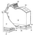
図1を参照すると、永久或は半永久カートリッジ・ボディ12に連結された交換可能なインクカートリッジ10が斜視図で示されている。このインクカートリッジ10は、ブラック、シアン、マゼンタ、或は、イェロー等の単色インクを含み得るか、或は、多色インクを含み得る。カートリッジ・ボディ12は単一カートリッジ10に結着されるように構成され得るか、或は、多重カートリッジ10を保持するように拡張され得る。単色インクのカートリッジ10の場合、カートリッジ・ボディ12は、それ自体のインクカートリッジ連結側面16とは反対側に、単一印刷ヘッド14を当該カートリッジ・ボディ12の側面に典型的には含む。多重カートリッジ10或は多色カートリッジ10の場合、カートリッジ・ボディ12は典型的には3つ或は4つの印刷ヘッド14等の多重印刷ヘッドを含み得る。
【0015】
高速で高品質な印刷動作において、カートリッジ・ボディ12が印刷ヘッドから熱を除去するように適合されていることが好ましい。これはアルミニウム或は亜鉛等の熱伝導性金属からカートリッジ・ボディ12を構築すること、及び/或は、熱伝導性フィン18を該ボディ12上に設けて熱を伝導或は対流によって印刷ヘッドから遠ざけるように伝導することによって達成され得る。
【0016】
インクカートリッジ10に関して、該カートリッジ10はハンドル22を含む上方部20と下方部24とを有する。ガス蓄積チャンバー26はカートリッジ10の下方部24に好ましくは結着されている。好適なガス蓄積チャンバー2の展開図が図2Aに示されている。
【0017】
ガス蓄積チャンバー26は、底部28、端部30及び32、側部34及び36、並びに、上方縁若しくは周辺部38を含んで、開放式キャビティ40を画成する。付勢装置42がキャビティ40内に配置され、実質的に不浸透性の可撓性部材44が上方周辺部38に沿って結着されて、閉じたガス蓄積チャンバー26を画成している。
【0018】
付勢部材42はキャビティ40内に、好ましくは初期的に圧縮状態で底部42及び可撓性部材44の間に配置された、好ましくは弾性板ばね装置である。付勢部材42の目的は、追ってより詳細に説明されるように、蓄積チャンバー26のインクジェット・カートリッジ・ボディへの連結に及んで、可撓性部材44をキャビティ40の底部28から遠ざかる方向へ可撓性部材44を付勢することである。広範な付勢部材42が用いられ得、限定されることはないが、例えばコイルばね及び弾性エラストマー連続気泡フォーム材を含む。有用な弾性エラストマー材は、限定されることはないが、未フェルト状エーテル或はエステル型ポリウレタン・フォーム及び連続気泡ポリオレフィン・フォーム等を含む。そうしたフォーム材は、例えば、完全に詳述されている如くに引用することでここに合体させるDayに対する米国特許第5,400,067号に記載されている。
【0019】
可撓性部材44は、好ましくは、キャビティ40の上方縁若しくは周辺部38に結着される低密度のポリエチレン・フィルム、ポリプロピレン・フィルム、セロハン、ビニル、並びに、その類等の弾性薄膜(フィルム)材から形成される。好ましくは、気密封止(気密シール)がその可撓性部材44及び上方縁部の間にキャビティ40の周辺回りにおける可撓性部材44の縁を溶融することによって、及び/或は、接着剤を用いることによって形成される。クランプ・リング等々の他の手段が用いることができ、可撓性部材を封止状態で結着させ、ガス蓄積チャンバー26の開放式キャビティ40を閉じる。可撓性部材44は初期的にキャビティの底部28へ向かって付勢されることができ、それによって付勢部材42を引き裂き無しに或は過剰な伸張無しに押し下げるように為すために、当該可撓性部材44は弾性部材であることが好ましい。可撓性部材を底部へ向かって付勢することによって、キャビティ40の容積は初期的には最小化される。
【0020】
ガス蓄積チャンバー26は、ガス・フローチャネル48によってキャビティ40と流動に関して連通状態であるガス・インレットポート46をも含む。このガス・フローチャネル48は、好ましくは、約0.3mmから約3mmまでの範囲の幅と約0.3mmから3mmまでの高さとを有して、当該チャネル48を通じてガス泡が移動するに必要とされる圧力差を最小化している。そのキャビティ40内で初期減圧を有する蓄積チャンバー26を提供するために、可撓性部材44及び付勢部材42をキャビティ40の底部28へ向けて押し下げ、そしてガス・インレットポート46をポート封止装置50で封止することによってキャビティ40から空気を付勢させる。好適なポート封止装置50はエラストマー隔膜であり、それはニードル状装置によって穴開け可能であり、それらの間での空気或はガスの漏れを実質的に排除するために、その穴開けの後にニードル状装置の周辺回りを効果的に封止し得る。
【0021】
空気或はガスは、こうして、ポート封止装置50を穴開けすることによってガス蓄積チャンバー26内へ導入され得、それによって、空気或はガスがガス・インレットポート46からチャネル48を介してキャビティ40内へ流れるに連れて、付勢装置42が可撓性部材44を上方へ且つキャビティ40の底部28から遠ざかるように付勢する。付勢装置42は、それ故に、可撓性部材44が上方へ且つ底部28から遠ざかるように付勢されると共に、キャビティ40の容積が実行的に増大されることで吸引効果を引き起こす。
【0022】
図示の如く真空チャンバー26内のキャビティ40は、好ましくは、長寸で実質的に矩形状のキャビティ40である。キャビティ40は、好ましくは、約0.4から約6.0mmまでの範囲の拡張された容積を有する。本発明は、ガス蓄積チャンバー26、キャビティ40、或は、図2に示されるような他の構成要素の形状に限定されることを意図していなく、他の形状もそれら構成要素用に使用され得る。例えばガス蓄積チャンバー26は、もしキャビティ40がカートリッジのインク送りエリア及びカートリッジ・ボディから空気泡或はガス泡の除去のための充分な容積を有すれば、円筒、球状、長円、並びに、その類等々であることが可能である。
【0023】
可撓性部材44が底部28へ向けて初期的に押し下げられると共にガス・インレットポート46を隔膜50で封止した後、ガス蓄積チャンバー26全体はインクカートリッジ10に結着されて、可撓性部材44におけるキャビティとは反対側の面52がカートリッジ10の下方部24と隣接する(図1)。ガス蓄積チャンバー26はクリップ等によって下方部24と着脱自在に連結され得るか、或は、熱可塑性溶接技法若しくは接着剤の使用によってカートリッジ10と永久的に結着され得る。
【0024】
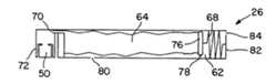
代替的なガス蓄積装置が図2B乃至図2Eにおいて概略断面で図示されている。これら図面において、ガス蓄積装置26は実質的に矩形状装置であり、ベローズ64とばね66若しくはばね68等の付勢部材とを含むベローズ・チャンバー62を備える。ベローズ64は、先に記載されたように、隔膜50を有するインレットポート72或はポートを封止するための他の手段を有するインレットポート72とガス・フローチャネル70を介して流動に関して連通状態である。ベローズ64は、好ましくは、ばね66或は68に結着された剛性プレート76と、該プレート76に結着されたピン78等のトリガー装置とを含む解放機構を含む。
【0025】
その初期状態において、ピン78はトリガー穴80と係合している。インクカートリッジのカートリッジ・ボディへの結着に及んで、トリガー解放装置は穴80内に挿入され、それによってピン78をそこから付勢する。図2Bにおいて、ばね66は圧縮状態であって、解放機構の起動に及んで、ばね66はプレート76を図2Cに示されるように、チャンバー62の反対側端部82へ向けて付勢する。図2Dにおいて、ばね68は伸張状態にあって、解放機構の起動に及んで、プレート76が図2Eに示されるようにばね68によって端部82へ向けて付勢される。空気穴84が好ましくは端部82に設けられて、解放機構の起動に及んで空気がチャンバー62から逃れることを可能としている。様々な解放機構が使用され得て、カートリッジがカートリッジ・ボディに結着された際のガス蓄積装置の起動までに、ベローズを圧縮状態に維持する。そうした解放機構は、ラッチ・ピン、レバー、カム、並びに、その類を含むことができて、ばね66を圧縮状態に、或は、ばね68を伸張状態に維持する。理解して頂けるように、チャンバー62内のベローズ64は、吸引器や、ベローズ若しくは吸引器を、ばね66或は68の必要性無しに、圧縮状態から膨張状態へ膨張させるに充分な弾性及び固有の復原力を有するベローズ装置等の球根状チャンバーによって代替可能である。
【0026】
本発明の別の重要な特徴は、図3の断面図に示されるインク濾過及び空気除去システム90である。空気除去システム90はガス蓄積チャンバー26と協働して、インクカートリッジが当該システム90にインストールされた際、封止装置50が穴開けされて、キャビティ40の容積の膨張(図2A)或はベローズ64の膨張(図2B乃至図2E)に及んで、カートリッジからの空気泡或はガス泡を除去するための吸引効果を生ずる。
【0027】
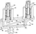
インク濾過及び空気除去システム90は、インク送りニードル弁アセンブリ92と、長寸の実質的に矩形状のフィルタ・キャビティ98の上方部96に結着されたガス除去ニードル弁アセンブリ94と含む。フィルタ・キャビティ98は上方部96、側壁100、両端部壁102、並びに、底部104によって画成されている。インク・アウトレットポート106は底部104に結着され、濾過済みインクとフィルタ・キャビティ98のガス・チャンバー108と流動に関して連通状態である。アウトレットポート106は、好ましくは、封止状態で濾過及び空気除去システム90をカートリッジ・ボディと連結すべく使用されるかえし、ポール(pall)、或は、溝を含む。
【0028】
インク、空気、或は、ガスは、上部96に結着された長寸のインク・ニードル114及びインク・インレットポート116を通じて、フィルタ・キャビティ98の上方部112内に流れ込む。屑及び不純物はフィルタ素子118によって上方部112内のインクから除去されて、純化されたインクが濾過インク及びガスのチャンバー108内に蓄積する。フィルタ素子118は角度が付けられフィルタ・キャビティ98内に水平に配置されておらず、空気泡或はガス泡が、ガス除去ニードル弁アセンブリ94に隣接するキャビティ98のガス蓄積エリア120内に蓄積するように為す。ガス除去ニードル弁アセンブリ94は長寸のガス除去ニードル122を収容し、そのガス除去ニードルが、フィルタ・キャビティ98の上方部96に形成されたガス除去ポート124によってガス蓄積エリア120と流動に関して連通している。
【0029】
図3に示された濾過及び空気除去システムの詳細は、図4を更に参照してシステム90の展開図で見ることができる。図から明らかなようにニードル弁アセンブル92,94は、好ましくは、実質的に同一である。これらアセンブリ92,94は長寸のニードル114,122をそれぞれ含み、それらニードルはポート116,124と、O-リング130,132等の弾性封止装置によってそれぞれ封止状態で結着されている。弁ばね134,136はニードル・フランジ138,140及びばね付勢装置142,144の間の長寸ニードル114,122回りにそれぞれ配置されている。ばね付勢装置142,144は円筒状弁146,148をそれぞれ担持し、それら円筒状弁は長寸ニードル114,122を貫通させるように内部に受け取る環状開口150,152を有する。弁ガイド154,156は上部96に結着され、ばね付勢装置142,144のフランジ162,164と係合する弁移動停止棚部158,160を収容する。
【0030】
それらの閉位置において、弁146,148はばね124,136によって上部96から遠ざかるように付勢されて、弁146,148が長寸ニードル114,122におけるインレット穴166,168を覆うように為す。インクカートリッジ10の結着に及んで、ばね付勢装置142,144は上方部96へ向かって付勢され、それによってばね134,136を押し下げ、弁146,148を降下させて、インク・インレット穴166及びガス・アウトレット穴168を露出する。インクカートリッジ10の取り外しに及んで、ばね134,136は弁146,148を上部96へ向けて再び付勢して、それら弁がインレット穴166及びガス・アウトレット穴168を再び覆って封止するように為す。
【0031】
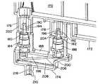
次に図5で参照されるように、インクカートリッジ170(カートリッジ10と同様)、ガス蓄積チャンバー172(ガス蓄積チャンバー26と同様)、並びに、濾過及び空気除去システム174(システム90と同様)の部分的な断面図が示されており、その濾過及び空気除去システム174がインクカートリッジ170と係合的に連結された状態である。インクカートリッジ170と濾過及び空気除去システム174とが連結されると、インク供給ポート176と空気泡若しくはガス泡除去ポート178は弁180及び182と係合し、次いで、それらはばね付勢装置184及び186を濾過及び空気除去装置174の上方部188へ向かって付勢する。弁180及び182を下方へ付勢する及んで、ニードル194及び196のインク・インレット穴190及びガス・アウトレット穴192は覆いが外れて、フィルタ・キャビティ198がインク・ニードル194によってインクカートリッジのインク・アウトレットポート176と流動に関して連通するように連結される。同様に、ガス蓄積エリア200は空気泡或はガス泡除去ポート178と流動に関して連通するように連結されて、空気及び/或はガスをガス・アウトレット・ニードル196を通じてガス蓄積チャンバー172内へ流す。
【0032】
インク・ニードル194に隣接するカートリッジからのインク流出に抗すべくインクカートリッジ170のインク供給ポート176を封止するために、インク供給ポート176は、好ましくは、ニードル194と封止状態で係合する弾性エラストマー隔膜202を収容する。同様に、空気泡或はガス泡除去ポート178は、好ましくは、ニードル196と封止状態で係合する隔膜204を収容する。フィルタ・キャビティ198へのインク流入に及んで、インクはフィルタ206によって粒子及び屑を除去すべく濾過されて、純化されたインクが濾過インク部208内へ流入し、インク供給ポート210からカートリッジ・ボディ内へ流出させる。
【0033】
濾過及び空気除去装置174のカートリッジ・ボディ212(図6)への連結は、インク供給ポート210をカートリッジ・ボディ212における穴或はアパチャー214内へ挿入することによって実行され得る。インク供給ポート210をアパチャー214に封止状態で連結するために、弾性エラストマーのブッシュ、カラー、或は、O-リング216がアパチャー214内へ挿入されるか、或は、インク供給ポート210回りに配置されるかの何れかを為して、O-リングがその供給ポート210上の溝218と係合し、該O-リング216の外側面領域220をアパチャー214の内側面領域222に対して密に隣接した状態に強制させる。O-リング216は、好ましくは、限定されることはないが、天然ゴム、合成ゴム、ポリウレタン・フォーム、エチレン-プロピレン-ジエン・モノマー(EPDM)、シリコーン等々を含むエラストマー材料から形成される。但し、O-リング用に選択された材料が耐インク性であり、そこを通じてのインク或は空気の漏洩を防止すべく封止を効果的に形成すると云う条件である。他の手段を用いることができ、インク供給ポート210とカートリッジ・ボディ212におけるアパチャー214との間の連結を封止することもでき、それには、限定されることはないが、O-リング216の有無に拘わらず接着剤の使用、エラストマー製のブッシュ或はカラーの使用、並びに、濾過及び空気除去装置174のカートリッジ・ボディ212への熱可塑性溶接等々を含む。
【0034】
本発明の様々な局面及び実施例やそれらの幾つかの長所を説明したが、当業者には理解して頂けるように、本発明は特許請求の範囲の精神及び範囲内において、様々な変更、代替、並びに、修正を受け入れることができる。
【図面の簡単な説明】
【図1】 図1は、インクジェット・プリンタとして使用するためにカートリッジ・ボディに組み付けられた着脱自在のインク供給カートリッジの斜視図である。
【図2】 図2Aは、本発明に従った空気泡或はガス泡除去装置の斜視した場合の展開図であり、図2B乃至図2Eは、本発明の代替的な空気泡或はガス泡除去装置の概略断面図である。
【図3】 図3は、本発明の空気泡或はガス泡除去装置と組み合わせて使用されるフィルタ・タワー及び空気除去構造の斜視断面図である。
【図4】 図4は、本発明の空気泡或はガス泡除去装置と組み合わせて使用されるフィルタ・タワー及び空気除去構造の斜視した場合の展開図である。
【図5】 図5は、本発明の空気泡或はガス泡除去装置を含む着脱自在インク供給カートリッジに組み付けられたフィルタ・タワー及び空気除去構造の断面図である。
【図6】 図6は、使い捨てインク供給カートリッジと共に使用されるカートリッジ・ボディの斜視図である。
【符号の説明】
10,170 インクカートリッジ
12,212 カートリッジ・ボディ
14 印刷ヘッド
26 ガス蓄積チャンバー
40 開放式キャビティ
42 付勢部材
44 可撓性部材
46 ガス・インレットポート
48 ガス・フローチャネル
50 隔膜
64 ベローズ
66,68 ばね
76 剛性プレート
84 空気穴
90 インク濾過及び空気除去システム
92 インク送りニードルベルアセンブリ
98 フィルタ・キャビティ
94 ガス除去ニードル弁アセンブリ
98 フィルタ・キャビティ
106 インク・アウトレットポート
108 ガス・チャンバー
116 インク・インレットポート
114 インク・ニードル
118 フィルタ素子
120 ガス蓄積エリア
174 濾過及び空気除去装置[0001]
Field of Invention
The present invention relates to ink jet printers, and more particularly to a mechanism and apparatus for removing air from an ink feed port of an ink jet printing apparatus.
[0002]
Background of the Invention
During the life of an inkjet pen, multiple air or gas bubbles grow in the ink and coalesce into larger bubbles. As such bubbles are formed and fused, they tend to accumulate inside the ink feed port, the filter area, and the ink feed channel in the ink pen. If the amount of air bubbles or gas bubbles increases significantly, pen performance can be affected. For disposable pens, air accumulation is typically not a significant problem. However, in the case of longer-life permanent pens or semi-permanent pens with cartridge bodies and individual replaceable ink cartridges, or in the case of high quality, high speed printing devices, substantial accumulation of air bubbles or gas bubbles is a problem. obtain.
[0003]
Some of the air or gas bubbles in the ink flow channel in the pen are removed from the pen through the pen's ink discharge orifice during printing. However, some of the air bubbles or gas bubbles can be found in the return path leading to the ink feed path into the ink feed port at the connection between the cartridge body and the ink cartridge. Air bubbles or gas bubbles can also accumulate by other mechanisms in the ink feed port between the cartridge body and the ink cartridge. When ink is introduced into the ink cartridge, a significant amount of dissolved air is included with the ink. As the ink is heated in the cartridge or in the print head, its capacity for dissolved air is reduced and air or gas bubbles are released from the ink. Another source of air or gas bubbles in the ink feed port in the pen results from removal and connection of the ink cartridge from the cartridge body. If the consumable ink cartridge is allowed to proceed with ink drying, the ink feed port connecting the cartridge to the cartridge body will be filled with air. Even if ink drying of the ink cartridge is not progressing, a specific amount of air is introduced into the ink feed port each time the ink cartridge is connected to and / or disconnected from the cartridge body.
[0004]
Priming the pen by ejecting ink allows printing to remove air or gas bubbles from the print head itself, but replacing the ink cartridge can still leave a substantial amount of air in the ink feed port. . This air is effectively trapped between the cartridge body and the ink cartridge in a connection port that connects the cartridge to the cartridge body.
[0005]
It is an object of the present invention to provide a mechanism and method for removing air bubbles and gas bubbles from an ink jet pen.
[0006]
Another object of the present invention is to provide an apparatus for removing a substantial amount of air and a minimum amount of ink from an ink feed port.
[0007]
Yet another object of the present invention is to provide a substantially automatic air removal system that is activated upon ink cartridge replacement.
[0008]
Another object of the present invention is to improve the operation of permanent or semi-permanent ink jet pens.
[0009]
Summary of the Invention
With respect to the previous objectives and advantages and other objectives and advantages, the present invention provides an apparatus for removing air or gas bubbles from an ink jet pen, the apparatus comprising a gas reservoir attached to an ink cartridge. A chamber and a gas inlet port in fluid communication with the chamber, the inlet port having a diaphragm or other means for sealing the port, the chamber comprising a gas storage device and its gas A biasing member that biases the storage device, and is configured to draw gas from the cartridge body into the chamber through the inlet port when the cartridge is attached to the cartridge body.
[0010]
In another aspect, the present invention provides an ink cartridge, and provides an ink cartridge including a bellows device for removing air bubbles or gas bubbles from an ink feed port for an ink jet pen, and the bellows device. Is a variable volume chamber, a biasing device that increases the volume of the chamber from an initial minimized volume, an air inlet port in fluid communication with the chamber, and effectively sealing the chamber and the port to And a sealing member that maintains a minimum chamber volume.
[0011]
In yet another aspect, the present invention provides an ink jet pen, the ink jet pen comprising a cartridge body containing one or more permanent or semi-permanent print heads; A replaceable ink cartridge including a filtration and air removal system connected to the cartridge body in communication with ink flow and an ink supply for supplying ink to the print head, and detachable from the filtration and air removal system A replaceable ink cartridge connected to the ink cartridge, an air bubble or gas bubble removing device attached to the ink cartridge, an air bubble or gas bubble removing device including a vacuum chamber, and a fluid flow with the vacuum chamber A vacuum release port that communicates with the vacuum release that includes a diaphragm that seals the port The vacuum chamber defines an open cavity, and includes a bottom, a top, and both sides, and a bellows member is attached to an upper edge around the periphery of the open cavity. A biasing device is arranged between the bellows member and the bottom in the cavity.
[0012]
An advantage of the air bubble or gas bubble removal system of the present invention is that the air bubble or gas bubble removal device is configured to be activated substantially automatically upon ink cartridge replacement without any other operator intervention. That is. Unlike a priming or back pressure control device, the device of the present invention is adapted for the removal of air bubbles or gas bubbles so that only gas and / or a minimum amount of ink is transferred to the ink cartridge, cartridge body, and / or. Is removed from the ink supply port. The priming device typically only removes air from the print head and the ink path that is free of the print head, and to remove air bubbles from the ink feed port in the connection between the cartridge body and the ink cartridge. Not effective. Similarly, the cartridge pressure device may reduce the formation of air bubbles within the ink cartridge itself by increasing the ink pressure within the ink cartridge, but as the cartridge dries or the new ink cartridge is removed and installed In this case, it is substantially ineffective to remove air bubbles or gas bubbles introduced into the ink feed port. As described below, the present invention provides a substantial improvement in the ability to remove air or gas bubbles from the ink feed port of an inkjet pen.
[0013]
Further advantages of the present invention will become apparent from the detailed description considered in conjunction with the accompanying drawings, in which like reference numerals indicate like elements throughout the several views.
[0014]
Detailed Description of the Invention
Referring to FIG. 1, a
[0015]
In high speed, high quality printing operations, the
[0016]
With respect to the
[0017]
The
[0018]
The biasing
[0019]
The
[0020]
The
[0021]
Air or gas can thus be introduced into the
[0022]
As shown, the
[0023]
After the
[0024]
An alternative gas storage device is shown in schematic cross-section in FIGS. 2B-2E. In these drawings, the
[0025]
In its initial state, the
[0026]
Another important feature of the present invention is the ink filtration and
[0027]
The ink filtration and
[0028]
Ink, air, or gas flows into the
[0029]
Details of the filtration and air removal system shown in FIG. 3 can be seen in an exploded view of the
[0030]
In their closed position,
[0031]
Referring now to FIG. 5, portions of ink cartridge 170 (similar to cartridge 10), gas storage chamber 172 (similar to gas storage chamber 26), and filtration and air removal system 174 (similar to system 90). A schematic cross-sectional view is shown with its filtration and
[0032]
In order to seal the
[0033]
The coupling of the filtration and
[0034]
While various aspects and embodiments of the invention and some of their advantages have been described, it will be appreciated by those skilled in the art that the invention is susceptible to various modifications, within the spirit and scope of the appended claims. Alternatives as well as modifications can be accepted.
[Brief description of the drawings]
FIG. 1 is a perspective view of a removable ink supply cartridge assembled to a cartridge body for use as an ink jet printer.
2A is a perspective exploded view of an air bubble or gas bubble removal device according to the present invention, and FIGS. 2B-2E are alternative air bubbles or gas bubbles of the present invention. It is a schematic sectional drawing of a removal apparatus.
FIG. 3 is a perspective cross-sectional view of a filter tower and air removal structure used in combination with the air bubble or gas bubble removal device of the present invention.
FIG. 4 is an exploded perspective view of a filter tower and an air removal structure used in combination with the air bubble or gas bubble removal device of the present invention.
FIG. 5 is a cross-sectional view of a filter tower and air removal structure assembled to a removable ink supply cartridge including an air bubble or gas bubble removal device of the present invention.
FIG. 6 is a perspective view of a cartridge body used with a disposable ink supply cartridge.
[Explanation of symbols]
10,170 Ink cartridge
12,212 Cartridge body
14 Print head
26 Gas accumulation chamber
40 open cavity
42 Biasing member
44 Flexible member
46 Gas inlet port
48 Gas Flow Channel
50 diaphragm
64 Bellows
66, 68 spring
76 Rigid plate
84 Air hole
90 Ink filtration and air removal system
92 Ink Feed Needle Bell Assembly
98 Filter cavity
94 Gas Removal Needle Valve Assembly
98 Filter cavity
106 Ink outlet port
108 Gas chamber
116 Ink inlet port
114 Ink Needle
118 Filter element
120 Gas storage area
174 Filtration and air removal device
Claims (18)
Translated fromJapaneseApplications Claiming Priority (3)
| Application Number | Priority Date | Filing Date | Title |
|---|---|---|---|
| US09/291,028US6139138A (en) | 1999-04-13 | 1999-04-13 | Bellows system for an ink jet pen |
| US09/291,028 | 1999-04-13 | ||
| PCT/US2000/009594WO2000061373A1 (en) | 1999-04-13 | 2000-04-11 | Bellows system for an ink jet pen |
Publications (2)
| Publication Number | Publication Date |
|---|---|
| JP2002540998A JP2002540998A (en) | 2002-12-03 |
| JP3831806B2true JP3831806B2 (en) | 2006-10-11 |
Family
ID=23118529
Family Applications (1)
| Application Number | Title | Priority Date | Filing Date |
|---|---|---|---|
| JP2000610678AExpired - Fee RelatedJP3831806B2 (en) | 1999-04-13 | 2000-04-11 | Inkjet pen bellows system |
Country Status (8)
| Country | Link |
|---|---|
| US (1) | US6139138A (en) |
| EP (1) | EP1175302B1 (en) |
| JP (1) | JP3831806B2 (en) |
| CN (2) | CN1144682C (en) |
| AU (1) | AU4227100A (en) |
| DE (1) | DE60004984T2 (en) |
| HK (1) | HK1046118B (en) |
| WO (1) | WO2000061373A1 (en) |
Families Citing this family (19)
| Publication number | Priority date | Publication date | Assignee | Title |
|---|---|---|---|---|
| US7114801B2 (en)* | 1995-04-27 | 2006-10-03 | Hewlett-Packard Development Company, L.P. | Method and apparatus for providing ink to an ink jet printing system |
| US7097274B2 (en)* | 2004-01-30 | 2006-08-29 | Hewlett-Packard Development Company, L.P. | Removing gas from a printhead |
| US9452605B2 (en)* | 2007-10-25 | 2016-09-27 | Hewlett-Packard Development Company, L.P. | Bubbler |
| DE602006001896D1 (en)* | 2005-05-27 | 2008-09-04 | Brother Ind Ltd | Ink supply device |
| JP4841349B2 (en)* | 2006-07-29 | 2011-12-21 | 株式会社リコー | Liquid ejection head unit and image forming apparatus |
| JP4284556B2 (en)* | 2006-10-31 | 2009-06-24 | ブラザー工業株式会社 | Ink supply apparatus, ink cartridge, and inkjet image recording apparatus |
| WO2009096965A1 (en)* | 2008-01-31 | 2009-08-06 | Hewlett-Packard Development Company, L.P. | Apparatus and methods for purging air from a fluid conveying tube |
| CN201362042Y (en)* | 2009-03-19 | 2009-12-16 | 珠海天威技术开发有限公司 | Print carriage adapter and continuous ink supply system |
| US8376487B2 (en)* | 2009-11-09 | 2013-02-19 | Eastman Kodak Company | Air extraction printer |
| JP5565029B2 (en) | 2010-03-29 | 2014-08-06 | セイコーエプソン株式会社 | Liquid container and liquid consuming device |
| JP5340240B2 (en)* | 2010-04-02 | 2013-11-13 | キヤノン株式会社 | TANK AND PRINTER HAVING THE SAME |
| US20110279535A1 (en)* | 2010-05-17 | 2011-11-17 | Silverbrook Research Pty Ltd | Maintenance apparatus having rotatable wiper and transfer rollers for printhead |
| GB2481599B (en) | 2010-06-29 | 2012-07-18 | Linx Printing Tech | Ink jet printer |
| JP6638442B2 (en)* | 2016-02-09 | 2020-01-29 | セイコーエプソン株式会社 | Liquid container, liquid ejecting apparatus, and maintenance method for liquid ejecting apparatus |
| CN108778757B (en) | 2016-04-11 | 2020-05-26 | 惠普发展公司,有限责任合伙企业 | Device and system for coalescing frothed liquid |
| US11691432B2 (en) | 2018-02-26 | 2023-07-04 | Hewlett-Packard Development Company, L.P. | Air purger with plunger |
| US11833808B2 (en) | 2018-05-03 | 2023-12-05 | Hewlett-Packard Development Company, L.P. | Air purging |
| CN109733073B (en)* | 2019-03-04 | 2023-12-01 | 珠海益捷科技有限公司 | ink cartridge |
| CN109720100B (en)* | 2019-03-04 | 2023-12-01 | 珠海益捷科技有限公司 | Ink cartridge and expansion method thereof |
Family Cites Families (13)
| Publication number | Priority date | Publication date | Assignee | Title |
|---|---|---|---|---|
| JPS5924676A (en)* | 1982-07-31 | 1984-02-08 | Sharp Corp | Inkjet printer bubble remover |
| US4509062A (en)* | 1982-11-23 | 1985-04-02 | Hewlett-Packard Company | Ink reservoir with essentially constant negative back pressure |
| US4992802A (en)* | 1988-12-22 | 1991-02-12 | Hewlett-Packard Company | Method and apparatus for extending the environmental operating range of an ink jet print cartridge |
| JPH03258554A (en)* | 1990-03-09 | 1991-11-18 | Seikosha Co Ltd | Ink jet printer |
| US5420619A (en)* | 1992-05-04 | 1995-05-30 | Hewlett-Packard Company | On-line/off-line primer for ink jet cartridge |
| US5754207A (en)* | 1992-08-12 | 1998-05-19 | Hewlett-Packard Company | Volume indicating ink reservoir cartridge system |
| US5777646A (en)* | 1995-12-04 | 1998-07-07 | Hewlett-Packard Company | Self-sealing fluid inerconnect with double sealing septum |
| US5736992A (en)* | 1994-10-31 | 1998-04-07 | Hewlett-Packard | Pressure regulated free-ink ink-jet pen |
| JP2817656B2 (en)* | 1995-02-21 | 1998-10-30 | 富士ゼロックス株式会社 | Ink supply device and recording device |
| US5721577A (en)* | 1995-05-04 | 1998-02-24 | Calcomp Inc. | Large capacity ink cartridge |
| US5812155A (en)* | 1995-10-27 | 1998-09-22 | Hewlett-Packard Company | Apparatus for removing air from an ink-jet print cartridge |
| US5815182A (en)* | 1995-12-04 | 1998-09-29 | Hewlett-Packard Company | Fluid interconnect for ink-jet pen |
| US5905518A (en)* | 1998-04-29 | 1999-05-18 | Hewlett-Packard Company | One shot air purge for replaceable ink supply |
- 1999
- 1999-04-13USUS09/291,028patent/US6139138A/ennot_activeExpired - Lifetime
- 2000
- 2000-04-11DEDE60004984Tpatent/DE60004984T2/ennot_activeExpired - Lifetime
- 2000-04-11HKHK02107050.0Apatent/HK1046118B/ennot_activeIP Right Cessation
- 2000-04-11CNCNB008062366Apatent/CN1144682C/ennot_activeExpired - Fee Related
- 2000-04-11EPEP00922027Apatent/EP1175302B1/ennot_activeExpired - Lifetime
- 2000-04-11WOPCT/US2000/009594patent/WO2000061373A1/enactiveIP Right Grant
- 2000-04-11CNCNA031381812Apatent/CN1515417A/enactivePending
- 2000-04-11AUAU42271/00Apatent/AU4227100A/ennot_activeAbandoned
- 2000-04-11JPJP2000610678Apatent/JP3831806B2/ennot_activeExpired - Fee Related
Also Published As
| Publication number | Publication date |
|---|---|
| DE60004984D1 (en) | 2003-10-09 |
| EP1175302A1 (en) | 2002-01-30 |
| AU4227100A (en) | 2000-11-14 |
| HK1046118A1 (en) | 2002-12-27 |
| CN1144682C (en) | 2004-04-07 |
| DE60004984T2 (en) | 2004-07-15 |
| CN1351542A (en) | 2002-05-29 |
| EP1175302A4 (en) | 2002-08-07 |
| EP1175302B1 (en) | 2003-09-03 |
| WO2000061373A1 (en) | 2000-10-19 |
| CN1515417A (en) | 2004-07-28 |
| US6139138A (en) | 2000-10-31 |
| HK1046118B (en) | 2004-10-21 |
| JP2002540998A (en) | 2002-12-03 |
Similar Documents
| Publication | Publication Date | Title |
|---|---|---|
| JP3831806B2 (en) | Inkjet pen bellows system | |
| US6270211B1 (en) | Bubble elimination and filter tower structure | |
| KR100588287B1 (en) | Ink cartridge and method of regulating fluid flow | |
| CN1076286C (en) | Ink supply device for inkjet printer | |
| US7618137B2 (en) | Ink jet recording system, ink cartridge and ink jet recording apparatus | |
| KR100254763B1 (en) | Ink refill techniques for an inkjet print cartridge which leave correct back pressure | |
| RU2318674C2 (en) | Ink cartridge, fluid medium flow regulator and method for regulating a flow of fluid medium | |
| JP3800807B2 (en) | Inkjet recording device | |
| US6776477B2 (en) | Mechanical seal cap for ink-cartridge | |
| US6244697B1 (en) | Filter tower for ink jet printhead | |
| JP3450916B2 (en) | Printer ink cartridges | |
| CN1891470A (en) | Ink cartridge for ink-jet recording equipment and ink-jet recording equipment |
Legal Events
| Date | Code | Title | Description |
|---|---|---|---|
| A131 | Notification of reasons for refusal | Free format text:JAPANESE INTERMEDIATE CODE: A131 Effective date:20050329 | |
| A601 | Written request for extension of time | Free format text:JAPANESE INTERMEDIATE CODE: A601 Effective date:20050628 | |
| A521 | Request for written amendment filed | Free format text:JAPANESE INTERMEDIATE CODE: A523 Effective date:20050817 | |
| A602 | Written permission of extension of time | Free format text:JAPANESE INTERMEDIATE CODE: A602 Effective date:20050804 | |
| A521 | Request for written amendment filed | Free format text:JAPANESE INTERMEDIATE CODE: A523 Effective date:20050929 | |
| A01 | Written decision to grant a patent or to grant a registration (utility model) | Free format text:JAPANESE INTERMEDIATE CODE: A01 Effective date:20060328 | |
| A61 | First payment of annual fees (during grant procedure) | Free format text:JAPANESE INTERMEDIATE CODE: A61 Effective date:20060428 | |
| A61 | First payment of annual fees (during grant procedure) | Free format text:JAPANESE INTERMEDIATE CODE: A61 Effective date:20060629 | |
| R150 | Certificate of patent or registration of utility model | Free format text:JAPANESE INTERMEDIATE CODE: R150 | |
| FPAY | Renewal fee payment (event date is renewal date of database) | Free format text:PAYMENT UNTIL: 20100728 Year of fee payment:4 | |
| LAPS | Cancellation because of no payment of annual fees |