JP3831743B2 - Ultrasonic catheter / probe - Google Patents
Ultrasonic catheter / probeDownload PDFInfo
- Publication number
- JP3831743B2 JP3831743B2JP2005251525AJP2005251525AJP3831743B2JP 3831743 B2JP3831743 B2JP 3831743B2JP 2005251525 AJP2005251525 AJP 2005251525AJP 2005251525 AJP2005251525 AJP 2005251525AJP 3831743 B2JP3831743 B2JP 3831743B2
- Authority
- JP
- Japan
- Prior art keywords
- transducer
- section
- electrical signal
- ultrasonic
- circuit element
- Prior art date
- Legal status (The legal status is an assumption and is not a legal conclusion. Google has not performed a legal analysis and makes no representation as to the accuracy of the status listed.)
- Expired - Lifetime
Links
- 239000000523sampleSubstances0.000titleclaimsdescription39
- 239000000463materialSubstances0.000claimsabstractdescription132
- 239000004020conductorSubstances0.000claimsabstractdescription54
- 238000002604ultrasonographyMethods0.000claimsabstractdescription34
- 238000000034methodMethods0.000claimsabstractdescription25
- 238000006243chemical reactionMethods0.000claimsdescription15
- 230000004044responseEffects0.000claimsdescription13
- 238000012285ultrasound imagingMethods0.000claimsdescription10
- 230000005540biological transmissionEffects0.000claimsdescription8
- 238000003780insertionMethods0.000claimsdescription8
- 230000037431insertionEffects0.000claimsdescription8
- TWNQGVIAIRXVLR-UHFFFAOYSA-Noxo(oxoalumanyloxy)alumaneChemical compoundO=[Al]O[Al]=OTWNQGVIAIRXVLR-UHFFFAOYSA-N0.000claimsdescription8
- 238000010521absorption reactionMethods0.000claimsdescription7
- 230000002792vascularEffects0.000claimsdescription5
- 238000002592echocardiographyMethods0.000claimsdescription3
- 210000005166vasculatureAnatomy0.000claimsdescription2
- 230000000694effectsEffects0.000abstractdescription2
- 230000015556catabolic processEffects0.000abstract1
- 238000006731degradation reactionMethods0.000abstract1
- 238000003384imaging methodMethods0.000description30
- 239000010410layerSubstances0.000description22
- 229910052451lead zirconate titanateInorganic materials0.000description13
- 239000000203mixtureSubstances0.000description13
- 230000035945sensitivityEffects0.000description12
- 239000012790adhesive layerSubstances0.000description10
- 238000002399angioplastyMethods0.000description9
- 238000004519manufacturing processMethods0.000description9
- 239000003566sealing materialSubstances0.000description9
- 230000008901benefitEffects0.000description8
- 238000012545processingMethods0.000description6
- 239000004593EpoxySubstances0.000description5
- 238000002059diagnostic imagingMethods0.000description5
- 229910000679solderInorganic materials0.000description5
- 210000001367arteryAnatomy0.000description4
- 230000000712assemblyEffects0.000description4
- 238000000429assemblyMethods0.000description4
- 210000004204blood vesselAnatomy0.000description4
- 230000008569processEffects0.000description4
- 239000011241protective layerSubstances0.000description4
- 238000003745diagnosisMethods0.000description3
- 230000005284excitationEffects0.000description3
- 230000004927fusionEffects0.000description3
- PCHJSUWPFVWCPO-UHFFFAOYSA-NgoldChemical compound[Au]PCHJSUWPFVWCPO-UHFFFAOYSA-N0.000description3
- 229910052737goldInorganic materials0.000description3
- 239000010931goldSubstances0.000description3
- 229920000052poly(p-xylylene)Polymers0.000description3
- 229920000647polyepoxidePolymers0.000description3
- 238000011282treatmentMethods0.000description3
- 238000009825accumulationMethods0.000description2
- 230000015572biosynthetic processEffects0.000description2
- 239000008280bloodSubstances0.000description2
- 210000004369bloodAnatomy0.000description2
- 239000012876carrier materialSubstances0.000description2
- 238000011109contaminationMethods0.000description2
- 210000004351coronary vesselAnatomy0.000description2
- 230000008878couplingEffects0.000description2
- 238000010168coupling processMethods0.000description2
- 238000005859coupling reactionMethods0.000description2
- 238000000151depositionMethods0.000description2
- 239000003822epoxy resinSubstances0.000description2
- 239000012530fluidSubstances0.000description2
- 230000006872improvementEffects0.000description2
- 239000003550markerSubstances0.000description2
- 208000010125myocardial infarctionDiseases0.000description2
- 230000002093peripheral effectEffects0.000description2
- KKJUPNGICOCCDW-UHFFFAOYSA-N7-N,N-Dimethylamino-1,2,3,4,5-pentathiocyclooctaneChemical compoundCN(C)C1CSSSSSC1KKJUPNGICOCCDW-UHFFFAOYSA-N0.000description1
- 239000004925Acrylic resinSubstances0.000description1
- 229920000178Acrylic resinPolymers0.000description1
- 229910018072Al 2 O 3Inorganic materials0.000description1
- RYGMFSIKBFXOCR-UHFFFAOYSA-NCopperChemical compound[Cu]RYGMFSIKBFXOCR-UHFFFAOYSA-N0.000description1
- 229920001651CyanoacrylatePolymers0.000description1
- 241000233805PhoenixSpecies0.000description1
- 230000004913activationEffects0.000description1
- 238000003491arrayMethods0.000description1
- 210000000013bile ductAnatomy0.000description1
- 230000017531blood circulationEffects0.000description1
- 210000001124body fluidAnatomy0.000description1
- 239000010839body fluidSubstances0.000description1
- QXJJQWWVWRCVQT-UHFFFAOYSA-Kcalcium;sodium;phosphateChemical compound[Na+].[Ca+2].[O-]P([O-])([O-])=OQXJJQWWVWRCVQT-UHFFFAOYSA-K0.000description1
- 230000000747cardiac effectEffects0.000description1
- 201000001883cholelithiasisDiseases0.000description1
- 239000011248coating agentSubstances0.000description1
- 238000000576coating methodMethods0.000description1
- 238000012790confirmationMethods0.000description1
- 238000010276constructionMethods0.000description1
- 238000007796conventional methodMethods0.000description1
- 229920001577copolymerPolymers0.000description1
- 229910052802copperInorganic materials0.000description1
- 239000010949copperSubstances0.000description1
- 238000007887coronary angioplastyMethods0.000description1
- 230000006866deteriorationEffects0.000description1
- 230000000916dilatatory effectEffects0.000description1
- 239000000945fillerSubstances0.000description1
- 238000010304firingMethods0.000description1
- 208000001130gallstonesDiseases0.000description1
- 238000007689inspectionMethods0.000description1
- 239000011810insulating materialSubstances0.000description1
- 230000010354integrationEffects0.000description1
- 238000013532laser treatmentMethods0.000description1
- HFGPZNIAWCZYJU-UHFFFAOYSA-Nlead zirconate titanateChemical compound[O-2].[O-2].[O-2].[O-2].[O-2].[Ti+4].[Zr+4].[Pb+2]HFGPZNIAWCZYJU-UHFFFAOYSA-N0.000description1
- WABPQHHGFIMREM-UHFFFAOYSA-Nlead(0)Chemical group[Pb]WABPQHHGFIMREM-UHFFFAOYSA-N0.000description1
- 238000005259measurementMethods0.000description1
- 238000012986modificationMethods0.000description1
- 230000004048modificationEffects0.000description1
- 238000012806monitoring deviceMethods0.000description1
- 238000012544monitoring processMethods0.000description1
- 239000002245particleSubstances0.000description1
- 230000000704physical effectEffects0.000description1
- 230000010287polarizationEffects0.000description1
- 229920000642polymerPolymers0.000description1
- 229920005989resinPolymers0.000description1
- 239000011347resinSubstances0.000description1
- 239000004065semiconductorSubstances0.000description1
- 238000010008shearingMethods0.000description1
- 229910052709silverInorganic materials0.000description1
- 239000004332silverSubstances0.000description1
- 238000004544sputter depositionMethods0.000description1
- 230000002966stenotic effectEffects0.000description1
- 230000000007visual effectEffects0.000description1
Images


Classifications
- A—HUMAN NECESSITIES
- A61—MEDICAL OR VETERINARY SCIENCE; HYGIENE
- A61B—DIAGNOSIS; SURGERY; IDENTIFICATION
- A61B8/00—Diagnosis using ultrasonic, sonic or infrasonic waves
- A61B8/12—Diagnosis using ultrasonic, sonic or infrasonic waves in body cavities or body tracts, e.g. by using catheters
- A—HUMAN NECESSITIES
- A61—MEDICAL OR VETERINARY SCIENCE; HYGIENE
- A61B—DIAGNOSIS; SURGERY; IDENTIFICATION
- A61B8/00—Diagnosis using ultrasonic, sonic or infrasonic waves
- A61B8/06—Measuring blood flow
- A—HUMAN NECESSITIES
- A61—MEDICAL OR VETERINARY SCIENCE; HYGIENE
- A61B—DIAGNOSIS; SURGERY; IDENTIFICATION
- A61B8/00—Diagnosis using ultrasonic, sonic or infrasonic waves
- A61B8/44—Constructional features of the ultrasonic, sonic or infrasonic diagnostic device
- A61B8/4444—Constructional features of the ultrasonic, sonic or infrasonic diagnostic device related to the probe
- A61B8/445—Details of catheter construction
- A—HUMAN NECESSITIES
- A61—MEDICAL OR VETERINARY SCIENCE; HYGIENE
- A61B—DIAGNOSIS; SURGERY; IDENTIFICATION
- A61B8/00—Diagnosis using ultrasonic, sonic or infrasonic waves
- A61B8/44—Constructional features of the ultrasonic, sonic or infrasonic diagnostic device
- A61B8/4483—Constructional features of the ultrasonic, sonic or infrasonic diagnostic device characterised by features of the ultrasound transducer
- A61B8/4488—Constructional features of the ultrasonic, sonic or infrasonic diagnostic device characterised by features of the ultrasound transducer the transducer being a phased array
- A—HUMAN NECESSITIES
- A61—MEDICAL OR VETERINARY SCIENCE; HYGIENE
- A61B—DIAGNOSIS; SURGERY; IDENTIFICATION
- A61B8/00—Diagnosis using ultrasonic, sonic or infrasonic waves
- A61B8/44—Constructional features of the ultrasonic, sonic or infrasonic diagnostic device
- A61B8/4483—Constructional features of the ultrasonic, sonic or infrasonic diagnostic device characterised by features of the ultrasound transducer
- A61B8/4494—Constructional features of the ultrasonic, sonic or infrasonic diagnostic device characterised by features of the ultrasound transducer characterised by the arrangement of the transducer elements
- B—PERFORMING OPERATIONS; TRANSPORTING
- B06—GENERATING OR TRANSMITTING MECHANICAL VIBRATIONS IN GENERAL
- B06B—METHODS OR APPARATUS FOR GENERATING OR TRANSMITTING MECHANICAL VIBRATIONS OF INFRASONIC, SONIC, OR ULTRASONIC FREQUENCY, e.g. FOR PERFORMING MECHANICAL WORK IN GENERAL
- B06B1/00—Methods or apparatus for generating mechanical vibrations of infrasonic, sonic, or ultrasonic frequency
- B06B1/02—Methods or apparatus for generating mechanical vibrations of infrasonic, sonic, or ultrasonic frequency making use of electrical energy
- B06B1/06—Methods or apparatus for generating mechanical vibrations of infrasonic, sonic, or ultrasonic frequency making use of electrical energy operating with piezoelectric effect or with electrostriction
- B06B1/0607—Methods or apparatus for generating mechanical vibrations of infrasonic, sonic, or ultrasonic frequency making use of electrical energy operating with piezoelectric effect or with electrostriction using multiple elements
- B06B1/0622—Methods or apparatus for generating mechanical vibrations of infrasonic, sonic, or ultrasonic frequency making use of electrical energy operating with piezoelectric effect or with electrostriction using multiple elements on one surface
- B06B1/0633—Cylindrical array
- B—PERFORMING OPERATIONS; TRANSPORTING
- B06—GENERATING OR TRANSMITTING MECHANICAL VIBRATIONS IN GENERAL
- B06B—METHODS OR APPARATUS FOR GENERATING OR TRANSMITTING MECHANICAL VIBRATIONS OF INFRASONIC, SONIC, OR ULTRASONIC FREQUENCY, e.g. FOR PERFORMING MECHANICAL WORK IN GENERAL
- B06B1/00—Methods or apparatus for generating mechanical vibrations of infrasonic, sonic, or ultrasonic frequency
- B06B1/02—Methods or apparatus for generating mechanical vibrations of infrasonic, sonic, or ultrasonic frequency making use of electrical energy
- B06B1/06—Methods or apparatus for generating mechanical vibrations of infrasonic, sonic, or ultrasonic frequency making use of electrical energy operating with piezoelectric effect or with electrostriction
- B06B1/0644—Methods or apparatus for generating mechanical vibrations of infrasonic, sonic, or ultrasonic frequency making use of electrical energy operating with piezoelectric effect or with electrostriction using a single piezoelectric element
- B06B1/0662—Methods or apparatus for generating mechanical vibrations of infrasonic, sonic, or ultrasonic frequency making use of electrical energy operating with piezoelectric effect or with electrostriction using a single piezoelectric element with an electrode on the sensitive surface
- B06B1/067—Methods or apparatus for generating mechanical vibrations of infrasonic, sonic, or ultrasonic frequency making use of electrical energy operating with piezoelectric effect or with electrostriction using a single piezoelectric element with an electrode on the sensitive surface which is used as, or combined with, an impedance matching layer
- B—PERFORMING OPERATIONS; TRANSPORTING
- B06—GENERATING OR TRANSMITTING MECHANICAL VIBRATIONS IN GENERAL
- B06B—METHODS OR APPARATUS FOR GENERATING OR TRANSMITTING MECHANICAL VIBRATIONS OF INFRASONIC, SONIC, OR ULTRASONIC FREQUENCY, e.g. FOR PERFORMING MECHANICAL WORK IN GENERAL
- B06B1/00—Methods or apparatus for generating mechanical vibrations of infrasonic, sonic, or ultrasonic frequency
- B06B1/02—Methods or apparatus for generating mechanical vibrations of infrasonic, sonic, or ultrasonic frequency making use of electrical energy
- B06B1/06—Methods or apparatus for generating mechanical vibrations of infrasonic, sonic, or ultrasonic frequency making use of electrical energy operating with piezoelectric effect or with electrostriction
- B06B1/0644—Methods or apparatus for generating mechanical vibrations of infrasonic, sonic, or ultrasonic frequency making use of electrical energy operating with piezoelectric effect or with electrostriction using a single piezoelectric element
- B06B1/0662—Methods or apparatus for generating mechanical vibrations of infrasonic, sonic, or ultrasonic frequency making use of electrical energy operating with piezoelectric effect or with electrostriction using a single piezoelectric element with an electrode on the sensitive surface
- B06B1/0674—Methods or apparatus for generating mechanical vibrations of infrasonic, sonic, or ultrasonic frequency making use of electrical energy operating with piezoelectric effect or with electrostriction using a single piezoelectric element with an electrode on the sensitive surface and a low impedance backing, e.g. air
- G—PHYSICS
- G01—MEASURING; TESTING
- G01S—RADIO DIRECTION-FINDING; RADIO NAVIGATION; DETERMINING DISTANCE OR VELOCITY BY USE OF RADIO WAVES; LOCATING OR PRESENCE-DETECTING BY USE OF THE REFLECTION OR RERADIATION OF RADIO WAVES; ANALOGOUS ARRANGEMENTS USING OTHER WAVES
- G01S15/00—Systems using the reflection or reradiation of acoustic waves, e.g. sonar systems
- G01S15/88—Sonar systems specially adapted for specific applications
- G01S15/89—Sonar systems specially adapted for specific applications for mapping or imaging
- G01S15/8906—Short-range imaging systems; Acoustic microscope systems using pulse-echo techniques
- G01S15/8909—Short-range imaging systems; Acoustic microscope systems using pulse-echo techniques using a static transducer configuration
- G01S15/8915—Short-range imaging systems; Acoustic microscope systems using pulse-echo techniques using a static transducer configuration using a transducer array
- G—PHYSICS
- G01—MEASURING; TESTING
- G01S—RADIO DIRECTION-FINDING; RADIO NAVIGATION; DETERMINING DISTANCE OR VELOCITY BY USE OF RADIO WAVES; LOCATING OR PRESENCE-DETECTING BY USE OF THE REFLECTION OR RERADIATION OF RADIO WAVES; ANALOGOUS ARRANGEMENTS USING OTHER WAVES
- G01S15/00—Systems using the reflection or reradiation of acoustic waves, e.g. sonar systems
- G01S15/88—Sonar systems specially adapted for specific applications
- G01S15/89—Sonar systems specially adapted for specific applications for mapping or imaging
- G01S15/8906—Short-range imaging systems; Acoustic microscope systems using pulse-echo techniques
- G01S15/8979—Combined Doppler and pulse-echo imaging systems
- G—PHYSICS
- G01—MEASURING; TESTING
- G01S—RADIO DIRECTION-FINDING; RADIO NAVIGATION; DETERMINING DISTANCE OR VELOCITY BY USE OF RADIO WAVES; LOCATING OR PRESENCE-DETECTING BY USE OF THE REFLECTION OR RERADIATION OF RADIO WAVES; ANALOGOUS ARRANGEMENTS USING OTHER WAVES
- G01S15/00—Systems using the reflection or reradiation of acoustic waves, e.g. sonar systems
- G01S15/88—Sonar systems specially adapted for specific applications
- G01S15/89—Sonar systems specially adapted for specific applications for mapping or imaging
- G01S15/8906—Short-range imaging systems; Acoustic microscope systems using pulse-echo techniques
- G01S15/899—Combination of imaging systems with ancillary equipment
- G—PHYSICS
- G10—MUSICAL INSTRUMENTS; ACOUSTICS
- G10K—SOUND-PRODUCING DEVICES; METHODS OR DEVICES FOR PROTECTING AGAINST, OR FOR DAMPING, NOISE OR OTHER ACOUSTIC WAVES IN GENERAL; ACOUSTICS NOT OTHERWISE PROVIDED FOR
- G10K11/00—Methods or devices for transmitting, conducting or directing sound in general; Methods or devices for protecting against, or for damping, noise or other acoustic waves in general
- G10K11/004—Mounting transducers, e.g. provided with mechanical moving or orienting device
- G10K11/006—Transducer mounting in underwater equipment, e.g. sonobuoys
- G10K11/008—Arrays of transducers
- B—PERFORMING OPERATIONS; TRANSPORTING
- B06—GENERATING OR TRANSMITTING MECHANICAL VIBRATIONS IN GENERAL
- B06B—METHODS OR APPARATUS FOR GENERATING OR TRANSMITTING MECHANICAL VIBRATIONS OF INFRASONIC, SONIC, OR ULTRASONIC FREQUENCY, e.g. FOR PERFORMING MECHANICAL WORK IN GENERAL
- B06B2201/00—Indexing scheme associated with B06B1/0207 for details covered by B06B1/0207 but not provided for in any of its subgroups
- B06B2201/70—Specific application
- B06B2201/76—Medical, dental
- G—PHYSICS
- G01—MEASURING; TESTING
- G01S—RADIO DIRECTION-FINDING; RADIO NAVIGATION; DETERMINING DISTANCE OR VELOCITY BY USE OF RADIO WAVES; LOCATING OR PRESENCE-DETECTING BY USE OF THE REFLECTION OR RERADIATION OF RADIO WAVES; ANALOGOUS ARRANGEMENTS USING OTHER WAVES
- G01S15/00—Systems using the reflection or reradiation of acoustic waves, e.g. sonar systems
- G01S15/88—Sonar systems specially adapted for specific applications
- G01S15/89—Sonar systems specially adapted for specific applications for mapping or imaging
- G01S15/8906—Short-range imaging systems; Acoustic microscope systems using pulse-echo techniques
- G01S15/8909—Short-range imaging systems; Acoustic microscope systems using pulse-echo techniques using a static transducer configuration
- G01S15/8915—Short-range imaging systems; Acoustic microscope systems using pulse-echo techniques using a static transducer configuration using a transducer array
- G01S15/892—Short-range imaging systems; Acoustic microscope systems using pulse-echo techniques using a static transducer configuration using a transducer array the array being curvilinear
- G—PHYSICS
- G01—MEASURING; TESTING
- G01S—RADIO DIRECTION-FINDING; RADIO NAVIGATION; DETERMINING DISTANCE OR VELOCITY BY USE OF RADIO WAVES; LOCATING OR PRESENCE-DETECTING BY USE OF THE REFLECTION OR RERADIATION OF RADIO WAVES; ANALOGOUS ARRANGEMENTS USING OTHER WAVES
- G01S15/00—Systems using the reflection or reradiation of acoustic waves, e.g. sonar systems
- G01S15/88—Sonar systems specially adapted for specific applications
- G01S15/89—Sonar systems specially adapted for specific applications for mapping or imaging
- G01S15/8906—Short-range imaging systems; Acoustic microscope systems using pulse-echo techniques
- G01S15/8979—Combined Doppler and pulse-echo imaging systems
- G01S15/8981—Discriminating between fixed and moving objects or between objects moving at different speeds, e.g. wall clutter filter
- Y—GENERAL TAGGING OF NEW TECHNOLOGICAL DEVELOPMENTS; GENERAL TAGGING OF CROSS-SECTIONAL TECHNOLOGIES SPANNING OVER SEVERAL SECTIONS OF THE IPC; TECHNICAL SUBJECTS COVERED BY FORMER USPC CROSS-REFERENCE ART COLLECTIONS [XRACs] AND DIGESTS
- Y10—TECHNICAL SUBJECTS COVERED BY FORMER USPC
- Y10T—TECHNICAL SUBJECTS COVERED BY FORMER US CLASSIFICATION
- Y10T29/00—Metal working
- Y10T29/42—Piezoelectric device making
Landscapes
- Health & Medical Sciences (AREA)
- Engineering & Computer Science (AREA)
- Life Sciences & Earth Sciences (AREA)
- Physics & Mathematics (AREA)
- Remote Sensing (AREA)
- Radar, Positioning & Navigation (AREA)
- Acoustics & Sound (AREA)
- Radiology & Medical Imaging (AREA)
- Biophysics (AREA)
- Biomedical Technology (AREA)
- Heart & Thoracic Surgery (AREA)
- Medical Informatics (AREA)
- Molecular Biology (AREA)
- Surgery (AREA)
- Animal Behavior & Ethology (AREA)
- General Health & Medical Sciences (AREA)
- Public Health (AREA)
- Veterinary Medicine (AREA)
- Pathology (AREA)
- Nuclear Medicine, Radiotherapy & Molecular Imaging (AREA)
- Mechanical Engineering (AREA)
- Gynecology & Obstetrics (AREA)
- Computer Networks & Wireless Communication (AREA)
- General Physics & Mathematics (AREA)
- Multimedia (AREA)
- Hematology (AREA)
- Ultra Sonic Daignosis Equipment (AREA)
- Media Introduction/Drainage Providing Device (AREA)
- Surgical Instruments (AREA)
- Particle Formation And Scattering Control In Inkjet Printers (AREA)
Abstract
Description
Translated fromJapanese本発明は、広くは超音波画像形成の分野に関し、より詳しくは、比較的小さな体腔並びにその周囲の体液ないし体組織の様々な特性を判定するための超音波画像形成に関する。 The present invention relates generally to the field of ultrasound imaging, and more particularly to ultrasound imaging for determining various characteristics of relatively small body cavities and surrounding body fluids or tissues.
本出願人は、米国特許第4917097号(Proudian et al. )「Apparatus and Method for Imaging Small Cavities (小腔の画像形成のための装置及び方法)」の記載と、米国特許第5167233号(Eberle et al. )「Dilating and Imaging Apparatus(拡張術及び画像形成のための装置)」の記載とを、この言及をもって本開示に組み入れるものである。 Applicants have described US Pat. No. 4,917,097 (Proudian et al.) “Apparatus and Method for Imaging Small Cavities” and US Pat. No. 5,167,233 (Eberle et al.). al.) The description of “Dilating and Imaging Apparatus” is incorporated into this disclosure with this reference.
専門医が心臓発作の防止のために特に力を入れているのは、完全なまたは部分的な遮断が生じている心臓動脈の診断及び治療である。冠動脈の血管壁にプラクが蓄積することによって生じる動脈遮断を原因とする心臓発作の発生を防止するために、外科医は経皮経管冠動脈形成術(PTCAと呼ばれるが、「バルーン血管形成術」という呼び名の方が一般的である)を行なっており、それによって良好な結果を得ている。バルーン血管形成術を行なうには、動脈の障害発生部位にカテーテルを注意深く挿通する必要がある。外科医は、バルーンが動脈内の適切な位置に入ったことを確認したならば、動脈壁にプラクが蓄積したために遮断ないし狭窄が発生している血管内通路を拡張するために、そのカテーテルの膨張可能な部分を膨張させる。 It is the diagnosis and treatment of cardiac arteries in which complete or partial blockage occurs that specialists are particularly committed to preventing heart attacks. To prevent the occurrence of a heart attack caused by arterial blockage caused by the accumulation of plaque on the vessel wall of the coronary artery, the surgeon called percutaneous transluminal coronary angioplasty (PTCA, called “balloon angioplasty”) Nicknames are more common), which gives good results. In order to perform balloon angioplasty, it is necessary to carefully insert a catheter into a site where an artery is damaged. Once the surgeon confirms that the balloon has entered the proper position within the artery, the catheter is inflated to dilate the intravascular passage that is blocked or stenotic due to the accumulation of plaque in the artery wall. Inflate possible parts.
画像形成デバイスを使用して、ヒトの血管等の狭い囲繞領域の画像を治療及び診断に使用可能な画質で診断用画像ディスプレイ装置上に表示できるようにすることが望まれていることはいうまでもない。カテーテルの先端に超小型の超音波画像形成デバイスを搭載したものを使用して、冠動脈の内壁のリアルタイム画像を表示させるということが、既に公知になっている。このような装置を、ここでは超音波カテーテルと呼ぶことにする。 Needless to say, it is desired to use an image forming device to display an image of a narrow surrounding area such as a human blood vessel on a diagnostic image display device with an image quality usable for treatment and diagnosis. Nor. It is already known that a real-time image of the inner wall of a coronary artery is displayed using a catheter equipped with an ultra-small ultrasonic imaging device at the tip of a catheter. Such a device will be referred to herein as an ultrasound catheter.
公知の超音波カテーテルでは、電子回路部品一式が搭載される電子回路部品担持部材とトランスデューサ・アセンブリのバッキング材料とに、同一の材料が使用されている。この公知の超音波カテーテルに付随する欠点は、電子回路部品の担持部材として好適に使用できる材料に求められる物理的及び音響的特質と、高感度トランスデューサ材料を用いたトランスデューサ・アセンブリのためのバッキング材料として好適に使用できる材料に求められる物理的及び音響的特質とを、共に提供することのできる、担持部材とバッキング材料とに兼用できる材料を見つけることが困難だということにある。 In the known ultrasonic catheter, the same material is used for the electronic circuit component carrying member on which the set of electronic circuit components are mounted and the backing material of the transducer assembly. The disadvantages associated with this known ultrasound catheter are the physical and acoustic properties required of materials that can be suitably used as a carrier for electronic circuit components, and backing materials for transducer assemblies using high sensitivity transducer materials. In other words, it is difficult to find a material that can provide both the physical and acoustic characteristics required for a material that can be suitably used as a supporting member and a backing material.
上述の公知の超音波カテーテルの構造によれば構造及び組立が簡単になるという利点が得られるが、その構造にはある欠点が付随しており、その欠点は、バッキング材料としての必要条件と電子回路部品の担持部材としての必要条件とが、特殊でしかも互いに相容れないことに原因している。電子回路ボディを構成するための電子回路部品担持部材は、剛性が大きく、電子回路部品が発生する高温に耐えられるだけの耐熱性を有するものであることが求められている。ところが、電子回路ボディの必要条件を満足することのできる公知の電子回路部品担持部材の材料は、高感度が得られるチタン酸ジルコン酸鉛(PZT)組成物を用いた、現時点で好適であると考えられているトランスデューサ・アセンブリのためのバッキング材料としては不適当である。 While the known ultrasonic catheter structure described above has the advantage of simplicity of construction and assembly, the structure has certain drawbacks associated with the requirements for the backing material and the electronics. This is due to the fact that the requirements for the circuit component carrier are special and incompatible with each other. An electronic circuit component carrying member for constituting an electronic circuit body is required to have high rigidity and heat resistance enough to withstand the high temperatures generated by the electronic circuit component. However, a known electronic circuit component supporting member material that can satisfy the requirements of the electronic circuit body is suitable at the present time using a lead zirconate titanate (PZT) composition that provides high sensitivity. It is unsuitable as a backing material for the transducer assembly being considered.
この新しい、より高い感度が得られるPZT組成物をトランスデューサ材料として使用し、一方、公知の電子回路部品担持部材の材料を、そのトランスデューサのためのバッキング材料として使用した場合には、カテーテルが音響信号を受信ないし送信したときに、トランスデューサ・アセンブリに不都合なリンギングが発生する。このリンギングによって発生する信号のために、トランスデューサ・アセンブリが送出する信号の品質が劣化し、ひいては、より高感度のトランスデューサ材料を超音波カテーテルに用いたことによって期待できる利点までもが限られてしまう。また、リンギングに起因するこの信号品質の劣化によって、超音波カテーテルが提供する画像の画質も制約される。そして、その画質が制約されるための、医療用及び診断用の画像形成のための超音波カテーテルの有用性そのものまでもが制約されてしまう。 If this new, higher sensitivity PZT composition is used as the transducer material, while the known electronic component carrier material is used as the backing material for the transducer, the catheter will receive an acoustic signal. Inconvenience ringing occurs in the transducer assembly when receiving or transmitting. The signal generated by this ringing degrades the quality of the signal delivered by the transducer assembly, thus limiting the benefits that can be expected from using a more sensitive transducer material in the ultrasound catheter. . In addition, the image quality provided by the ultrasound catheter is limited by the deterioration of the signal quality caused by ringing. And since the image quality is restricted, the usefulness itself of the ultrasonic catheter for medical and diagnostic image formation is also restricted.
公知の超音波カテーテルでは、トランスデューサ電極が、静電容量を有する接着剤層を介してトランスデューサ層に結合されていた。先に言及したPZT組成物は、音響信号に対するより高い感度が得られるものであるため、それ以前に使用されていたより低い感度しか得られない強誘電体ポリマーのトランスデューサ材料に取って代わるものであると考えられている。PZT組成物は強誘電体コポリマーと比較して優れた感度を有するが、誘電率が大きいという性質も持っている。新材料であるPZT組成物にはインピーダンスが小さい(即ち、静電容量が大きい)という性質があるため、PZT組成物から成るトランスデューサ層を、静電容量を有する接着剤層を介してトランスデューサ電極に結合すると、PZT組成物を用いたことによって得られるはずであった信号感度の向上が無に帰してしまう。 In known ultrasound catheters, the transducer electrodes are coupled to the transducer layer via an adhesive layer having a capacitance. The PZT composition referred to above replaces the ferroelectric polymer transducer material that provides lower sensitivity than previously used because it provides higher sensitivity to acoustic signals. It is believed that. PZT compositions have superior sensitivity compared to ferroelectric copolymers, but also have the property of a high dielectric constant. Since the new material, PZT composition, has the property of low impedance (ie, high capacitance), the transducer layer made of PZT composition is connected to the transducer electrode through the adhesive layer having capacitance. When combined, the improvement in signal sensitivity that would have been obtained by using the PZT composition is neglected.
上記課題を解決するための本発明の超音波カテーテル・プローブは、超音波を発射し、その発射した超音波の超音波エコーから変換された電気信号を提供する、脈管内へ挿入して使用する超音波カテーテル・プローブにおいて、トランスデューサ・アレイと集積回路とを別々に支持する互いに材質の異なった複数のセクションを有するマルチセクション形ボディであって、トランスデューサのバッキングとして機能し第2セクションと比べて大きな音響エネルギ吸収率を有する第1材料から成る第1セクションと、集積回路を支持するための第2材料から成る第2セクションと、を含んでいるマルチセクション形ボディと、前記マルチセクション形ボディの前記第1セクションに取付けられたトランスデューサ・アセンブリであって、前記トランスデューサ・アレイを含んでおり、該トランスデューサ・アレイは、脈管内へ超音波を送信して、その送信した超音波の超音波エコーに応じて第1電気信号を生成するものである、トランスデューサ・アセンブリと、前記マルチセクション形ボディの前記第2セクションに取付けられた信号変換用集積回路であって、前記トランスデューサ・アセンブリから前記第1電気信号を受け取り、該第1電気信号を第2電気信号に変換し、そして、該第2電気信号を、該第2電気信号を伝送するための少なくとも1本の信号チャネルを含んでいるケーブルを介して、脈管の外部の環境へ送出する、信号変換用集積回路と、前記第1電気信号を前記トランスデューサ・アレイから前記信号変換用集積回路へ伝達する、前記トランスデューサ・アレイと前記信号変換用集積回路との間の複数の電気伝送経路と、を備えたことを特徴とする。 The ultrasonic catheter probe of the present invention for solving the above-described problems is used by being inserted into a vascular vessel that emits an ultrasonic wave and provides an electrical signal converted from an ultrasonic echo of the emitted ultrasonic wave. In an ultrasonic catheter probe, a multi-section body having a plurality of sections made of different materials and supporting a transducer array and an integrated circuit separately, and functions as a transducer backing and is larger than the second section. A multi-section body including a first section of a first material having an acoustic energy absorption rate; and a second section of a second material for supporting an integrated circuit; A transducer assembly attached to the first section, the transducer assembly comprising: A transducer array, wherein the transducer array transmits ultrasonic waves into the vessel and generates a first electrical signal in response to an ultrasonic echo of the transmitted ultrasonic waves A signal conversion integrated circuit attached to the second section of the multi-section body that receives the first electrical signal from the transducer assembly and converts the first electrical signal to a second electrical signal. And a signal conversion integration for delivering the second electrical signal to an environment outside the vessel via a cable including at least one signal channel for transmitting the second electrical signal. A transducer array for transmitting a first electrical signal from the transducer array to the signal converting integrated circuit; Characterized by comprising a plurality of electrical transmission path between the signal converter integrated circuit.
好ましくは、前記第1セクションと前記第2セクションとを互いに隣接させてガイド・ワイヤ・ルーメン上に取付けてある。
また好ましくは、前記第1材料が前記第2材料と比較して小さな音響インピーダンスを有する。Preferably, the first section and the second section are mounted on a guide wire lumen adjacent to each other.
Also preferably, the first material has a smaller acoustic impedance than the second material.
また好ましくは、前記第2材料が前記第1材料と比べて小さな熱膨張係数を有する。
また好ましくは、前記トランスデューサ・アセンブリが、トランスデューサ層に直接に結合した複数の導電用電極を含んでいる。Preferably, the second material has a smaller coefficient of thermal expansion than the first material.
Also preferably, the transducer assembly includes a plurality of conductive electrodes coupled directly to the transducer layer.
また好ましくは、前記トランスデューサ・アセンブリが、トランスデューサ層に直接に結合した連続した1つの層から成る導電用電極を含んでいる。
また好ましくは、前記トランスデューサ・アセンブリが、円筒面状の配列形態としたトランスデューサ・アレイを含んでいる。Also preferably, the transducer assembly includes a conductive electrode consisting of a continuous layer directly coupled to the transducer layer.
Also preferably, the transducer assembly includes a transducer array in the form of a cylindrical surface.
また好ましくは、前記トランスデューサ・アセンブリが、平面状の配列形態としたトランスデューサ・アレイを含んでいる。
また好ましくは、前記トランスデューサ・アレイを、脈管内の側方視野を提供するために前記マルチセクション形ボディの一側に配設してある。Preferably, the transducer assembly includes a transducer array in a planar arrangement.
Also preferably, the transducer array is disposed on one side of the multi-section body to provide a lateral view within the vessel.
また好ましくは、前記トランスデューサ・アレイを、脈管内の前方視野を提供するために前記マルチセクション形ボディの正面に配設してある。
また好ましくは、前記マルチセクション形ボディに近接した位置に配設したバルーン・セクションを含んでいる。Also preferably, the transducer array is disposed in front of the multi-section body to provide an anterior view within the vessel.
Preferably, it also includes a balloon section disposed proximate to the multi-section body.
また好ましくは、前記バルーンを、前記マルチセクション形ボディに先んじて挿入されるカテーテルの一部分に配設してある。
また好ましくは、前記複数の電気伝送経路が、複数のトランスデューサ接点から成るトランスデューサ接点集合を含んでおり、それら複数のトランスデューサ接点は、前記トランスデューサ・アレイの複数の導電用電極に結合していると共に前記トランスデューサ・アレイから横方向へ突出しており、それによって、前記複数の導電用電極を、前記第2セクション上に配設され前記信号変換用集積回路に電気的に結合した複数本の導体ラインに接続することを容易にしてある。Also preferably, the balloon is disposed on a portion of the catheter that is inserted prior to the multi-section body.
Also preferably, the plurality of electrical transmission paths includes a set of transducer contacts comprising a plurality of transducer contacts, the plurality of transducer contacts coupled to a plurality of conductive electrodes of the transducer array and the Projecting laterally from the transducer array, thereby connecting the plurality of conductive electrodes to a plurality of conductor lines disposed on the second section and electrically coupled to the integrated circuit for signal conversion. It is easy to do.
また好ましくは、前記複数のトランスデューサ接点が前記複数本の導体ラインと重なり合うようにしてあり、それによって、ギャップ・ウェルダを用いて前記複数のトランスデューサ接点の各々を前記複数の導体ラインのうちの対応する1本のずつの導体ラインに接続することを容易にしてある。 Also preferably, the plurality of transducer contacts overlap the plurality of conductor lines, whereby a gap welder is used to connect each of the plurality of transducer contacts to the corresponding one of the plurality of conductor lines. It is easy to connect to each conductor line.
また、上記課題を解決するための本発明の超音波画像形成カテーテルは、超音波を発射し、その発射した超音波の超音波エコーから変換された電気信号を提供する、脈管内へ挿入して使用する超音波画像形成カテーテルにおいて、少なくとも1本のルーメンを内蔵しているシャフトと、前記シャフトに取付けた超音波プローブと、を備えており、前記超音波プローブが、トランスデューサ・アレイと集積回路とを別々に支持する互いに材質の異なった複数のセクションを有するマルチセクション形ボディであって、トランスデューサのバッキングとして機能し第2セクションと比べて比較的大きな音響エネルギ吸収率を有する第1材料から成る第1セクションと、集積回路を支持するための第2材料から成る第2セクションとを含んでいるマルチセクション形ボディと、前記マルチセクション形ボディの前記第1セクションに取付けられたトランスデューサ・アセンブリであって、前記トランスデューサ・アレイを含んでおり、該トランスデューサ・アレイは、脈管内へ超音波を送信して、その送信した超音波の超音波エコーに応じて第1電気信号を生成するものである、トランスデューサ・アセンブリと、前記マルチセクション形ボディの前記第2セクションに取付けられた信号変換用集積回路であって、前記トランスデューサ・アセンブリから前記第1電気信号を受け取り、該第1電気信号を第2電気信号に変換し、そして、該第2電気信号を、該第2電気信号を伝送するための少なくとも1本の信号チャネルを含んでいるケーブルを介して、脈管の外部の環境へ送出する、信号変換用集積回路と、前記第1電気信号を前記トランスデューサ・アレイから前記信号変換用集積回路へ伝達する、前記トランスデューサ・アレイと前記信号変換用集積回路との間の複数の電気伝送経路と、を備えた画像形成デバイスである、ことを特徴とする。 Moreover, the ultrasonic imaging catheter of the present invention for solving the above-mentioned problems is inserted into a vascular vessel that emits an ultrasonic wave and provides an electric signal converted from an ultrasonic echo of the emitted ultrasonic wave. The ultrasound imaging catheter used comprises a shaft containing at least one lumen, and an ultrasound probe attached to the shaft, the ultrasound probe comprising a transducer array, an integrated circuit, and A multi-section body having a plurality of sections made of different materials and supporting each of the first section and the first section made of a first material that functions as a backing for the transducer and has a relatively large acoustic energy absorption rate compared to the second section. A module including a section and a second section of a second material for supporting the integrated circuit. A transducer assembly attached to the first section of the multi-section body and the first section of the multi-section body including the transducer array, the transducer array transmitting ultrasound into the vessel A transducer assembly for generating a first electrical signal in response to an ultrasonic echo of the transmitted ultrasonic wave, and an integrated circuit for signal conversion attached to the second section of the multi-section body. At least for receiving the first electrical signal from the transducer assembly, converting the first electrical signal to a second electrical signal, and transmitting the second electrical signal to the second electrical signal. A signal sent to the environment outside the vessel via a cable containing one signal channel A plurality of electrical transmission paths between the transducer array and the signal conversion integrated circuit that transmit the first electrical signal from the transducer array to the signal conversion integrated circuit; It is an image forming device provided.
さらに、上記課題を解決するための本発明の超音波脈管内カテーテル・プローブの組立方法は、トランスデューサ・アレイと集積回路とを別々に支持するためのマルチセクション形ボディを備え、該マルチセクション形ボディがトランスデューサのバッキングで構成された第1セクションと集積回路を支持するための第2セクションとを有する、超音波脈管内カテーテル・プローブの組立方法において、前記トランスデューサ・アレイを含んでいるトランスデューサ・アセンブリを前記マルチセクション形ボディの前記第1セクションに取付けるトランスデューサ・アセンブリ取付ステップであって、前記トランスデューサ・アレイは、脈管内へ超音波を送信して、その送信した超音波の超音波エコーに応じて第1電気信号を生成するものであり、該トランスデューサ・アセンブリは、複数のトランスデューサ接点から成るトランスデューサ接点集合を含んでおり、それら複数のトランスデューサ接点は、前記トランスデューサ・アレイの複数の導電用電極に結合していると共に前記トランスデューサ・アレイから横方向へ突出している、トランスデューサ・アセンブリ取付ステップと、信号変換用集積回路を前記マルチセクション形ボディの前記第2セクションに取付ける信号変換用集積回路取付ステップであって、該信号変換用集積回路は、前記トランスデューサ・アレイから前記第1電気信号を受け取って該第1電気信号を第2電気信号に変換し、該第2電気信号がケーブルを介して伝送されるようにしてあり、該ケーブルは前記マルチセクション形ボディを脈管の外部の環境へ接続しており前記第2電気信号を伝送するための少なくとも1本の信号チャネルを備えている、信号変換用集積回路取付ステップと、前記第1セクションと前記第2セクションとを隣接した位置に配置して、前記複数のトランスデューサ接点の各々が、前記信号変換用集積回路に信号伝達可能に接続された複数の導体ラインのうちの対応する1本ずつの導体ラインと重なり合うようにするセクション配置ステップと、互いに重なり合ったトランスデューサ接点と導体ラインとの組に局所的電流を供給してその組のトランスデューサ接点と導体ラインとを融着させる局所的電流供給ステップと、を含んでいることを特徴とする。 Furthermore, the method for assembling the ultrasonic intravascular catheter probe of the present invention for solving the above-mentioned problems includes a multi-section body for separately supporting a transducer array and an integrated circuit, and the multi-section body. A method of assembling an ultrasonic intravascular catheter probe having a first section comprised of a backing of the transducer and a second section for supporting the integrated circuit, comprising: a transducer assembly including said transducer array. A transducer assembly mounting step for mounting to the first section of the multi-section body, wherein the transducer array transmits ultrasonic waves into the vasculature and performs a first response in response to an ultrasonic echo of the transmitted ultrasonic waves; It generates 1 electrical signal The transducer assembly includes a set of transducer contacts comprised of a plurality of transducer contacts, the plurality of transducer contacts coupled to a plurality of conductive electrodes of the transducer array and from the transducer array. A transducer assembly mounting step projecting laterally; and a signal conversion integrated circuit mounting step for mounting the signal conversion integrated circuit to the second section of the multi-section body, the signal conversion integrated circuit comprising: Receiving the first electrical signal from the transducer array and converting the first electrical signal into a second electrical signal, wherein the second electrical signal is transmitted over a cable, Multi-section body with outer ring of vessel An integrated circuit for signal conversion comprising at least one signal channel for transmitting the second electrical signal, the first section and the second section being adjacent to each other. Arranging the sections so that each of the plurality of transducer contacts overlaps with a corresponding one of the plurality of conductor lines connected to the signal conversion integrated circuit so as to transmit signals. And a local current supplying step of supplying a local current to the pair of mutually overlapping transducer contact and conductor line to fuse the pair of transducer contact and conductor line. .
好ましくは、前記局所的電流供給ステップが、互いに重なり合ったトランスデューサ接点と導体ラインの各組にギャップ・ウェルダを用いて局所的電流を供給するステップを含んでいる。 Preferably, the local current supply step includes the step of supplying a local current using a gap welder to each set of transducer contact and conductor line that overlap each other.
[本発明の目的(効果)]
本発明の目的は、従来例によってこれまで得ることのできた超音波画像より優れた、実質的にリアルタイムの、比較的小さな体腔及びその周囲の体組織の超音波画像を提供することにある。[Object (effect) of the present invention]
It is an object of the present invention to provide a substantially real-time ultrasound image of a relatively small body cavity and surrounding body tissue that is superior to ultrasound images that have been obtained with conventional examples.
本発明の更なる目的は、画像の解像度を向上させるために、体腔の内壁からの反射信号に対する感度を向上させることにある。
本発明の更なる目的は、その他の目的を満たしつつ更に、リンギングをはじめとする、トランスデューサ・アセンブリが送受信する信号中のノイズの発生原因を現レベルに維持し、或いは現レベルより低下させることによって、より鮮鋭な体腔の画像を提供することにある。It is a further object of the present invention to improve the sensitivity to the reflected signal from the inner wall of the body cavity in order to improve the image resolution.
A further object of the present invention is to maintain the current cause of noise in signals transmitted and received by the transducer assembly, including ringing, while reducing the current level, while satisfying other purposes. It is to provide a sharper body cavity image.
本発明の更なる目的は、超音波カテーテルのトランスデューサ・アセンブリに用いられる非常に小さなトランスデューサ・エレメントを、より容易に製造する手段を提供することにある。 It is a further object of the present invention to provide a means for more easily manufacturing very small transducer elements used in ultrasound catheter transducer assemblies.
本発明の更なる目的は、超音波カテーテルに用いられる非常に小さなトランスデューサ・エレメントを、非常に小さな公差で形成する手段を提供することにある。
本発明の更なる目的は、超音波カテーテルの電子回路ボディとトランスデューサ・アセンブリとに用いられる、好適な担持部材材料/バッキング材料を提供することにある。It is a further object of the present invention to provide a means for forming very small transducer elements used in ultrasound catheters with very small tolerances.
It is a further object of the present invention to provide a suitable carrier / backing material for use in the ultrasonic catheter electronics body and transducer assembly.
本発明の更なる目的は、超音波カテーテルの別々に製作したセクションである集積回路を包含しているセクションとトランスデューサ・アセンブリを包含しているセクションとの間の信号経路を提供するために、電子回路ボディの複数本の導体ラインをトランスデューサ・アセンブリの複数の導電用電極へ接続する手段を提供することにある。 A further object of the present invention is to provide a signal path between a section containing an integrated circuit, a separately fabricated section of an ultrasound catheter, and a section containing a transducer assembly. It is an object to provide a means for connecting a plurality of conductor lines of a circuit body to a plurality of conductive electrodes of a transducer assembly.
以上の様々な目的が本発明のカテーテル・プローブ・アセンブリによって達成される。本発明のカテーテル・プローブ・アセンブリは、体腔へ挿入するマルチセクション形ボディを備えている。このマルチセクション形ボディは、互いから分離し互いに材質が異なった、電子回路ボディとトランスデューサ・アセンブリとの夫々のための担持部材材料/バッキング材料を用いたことを特徴とする。本発明は、米国特許第4917097号(故 Proudian 他)や、米国特許第5167233号(Eberle et al. )に記載されているものと略々同タイプの超音波カテーテルに用いて実質的にリアルタイムの小体腔及びその周囲の体組織の画像を発生するための、プローブ・アセンブリを含むものである。 The various objects described above are achieved by the catheter probe assembly of the present invention. The catheter probe assembly of the present invention includes a multi-section body that is inserted into a body cavity. This multi-section body is characterized by the use of carrier / backing materials for the electronic circuit body and the transducer assembly, which are separated from each other and of different materials. The present invention is used in substantially real-time ultrasound catheters of the same type as those described in US Pat. No. 4,917,097 (later Proudian et al.) And US Pat. No. 5,167,233 (Eberle et al.). It includes a probe assembly for generating images of the body cavity and surrounding body tissue.
トランスデューサ・アセンブリは、複数のトランスデューサから成るトランスデューサ・アレイを備えており、マルチセクション形ボディの第1セクションに取付けられている。トランスデューサ・アレイは、体腔内へ超音波を送信し、複数のトランスデューサが受信した反射超音波に応答して電気信号を発生する。 The transducer assembly includes a transducer array comprising a plurality of transducers and is attached to a first section of a multi-section body. The transducer array transmits ultrasonic waves into the body cavity and generates electrical signals in response to reflected ultrasonic waves received by the plurality of transducers.
トランスデューサ・アセンブリのためのバッキング材料には、音響インピーダンスが小さく吸収率が大きいという特性を有する材料を特に選択している。音響インピーダンスの小さなバッキング材料は、そのバッキング材料の中へ結合された信号を吸収し、トランスデューサ・アセンブリに発生するリンギングの存続時間を短縮する。更に加えて、複数のトランスデューサ電極から成るトランスデューサ電極集合を、トランスデューサ材料に直接に結合してあり、それによって、以前はトランスデューサ回路に用いられていた静電容量を有する接着剤層をなくしている。 For the backing material for the transducer assembly, a material having a characteristic of low acoustic impedance and high absorption is particularly selected. A low acoustic impedance backing material absorbs signals coupled into the backing material and reduces the lifetime of ringing that occurs in the transducer assembly. In addition, a transducer electrode assembly consisting of a plurality of transducer electrodes is directly bonded to the transducer material, thereby eliminating the capacitive adhesive layer previously used in the transducer circuit.
複数の集積回路が、マルチセクション形ボディの第2セクションに取付けられている。第2セクションは、第1セクションから音響的に絶縁されており、熱膨張係数の小さな担持部材材料から成る。それら集積回路は、トランスデューサ・アセンブリの複数の電極とそれら集積回路の複数のパッドとを接続している複数本の導体を介して、トランスデューサ・アレイから、複数の電気信号から成る第1電気信号集合を受け取る。それら複数本の導体は、集積回路からトランスデューサ・アセンブリへ励振信号を送出するためにも使用される。集積回路は、受け取った第1電気信号集合を、複数の電気信号から成る第2電気信号集合に変換する。続いて集積回路は、その第2電気信号集合を、ケーブルを介して、体腔環境の外部に設置されている信号処理装置へ送出する。 A plurality of integrated circuits are attached to the second section of the multi-section body. The second section is acoustically insulated from the first section and is made of a carrier material having a low coefficient of thermal expansion. The integrated circuit includes a first electrical signal set comprising a plurality of electrical signals from the transducer array via a plurality of conductors connecting a plurality of electrodes of the transducer assembly and a plurality of pads of the integrated circuit. Receive. The multiple conductors are also used to send excitation signals from the integrated circuit to the transducer assembly. The integrated circuit converts the received first electric signal set into a second electric signal set made up of a plurality of electric signals. Subsequently, the integrated circuit sends the second set of electric signals to a signal processing device installed outside the body cavity environment via a cable.
この独特の、マルチセクション形のプローブ・アセンブリ構造を採用すれば、プローブ・アセンブリの設計者は、集積回路チップの担持部材に適した構造上及び音響上の特性を有する材料と、トランスデューサ・エレメントのバッキング材料に適した構造上及び音響上の特性を有する材料とを、個別に選択することができる。 With this unique, multi-section probe assembly structure, the probe assembly designer can use materials with structural and acoustic properties suitable for the carrier of the integrated circuit chip and transducer elements. Materials with structural and acoustic properties suitable for the backing material can be selected individually.
トランスデューサ・アセンブリと電子回路ボディとの、両方の部分の構成部品を損傷から保護するために、超音波カテーテル・プローブ・アセンブリのそれら2つの部分を別々に製造した上で、この超音波カテーテルの最終製造段階でそれら2つの部分を連結するようにしている。 In order to protect the components of both parts, the transducer assembly and the electronic circuit body, from damage, the two parts of the ultrasonic catheter probe assembly are manufactured separately and the final part of the ultrasonic catheter These two parts are connected at the manufacturing stage.
本発明それ自体、その目的、及びその利点は、以下の詳細な説明を添付図面と共に参照することによって最も良く理解することができよう。
これより本発明を、血管形成術に用いるカテーテルに関連させて説明して行くが、ただし、本発明がその用途に限定されるものではないことは明らかである。むしろ、本発明は、小体腔内での画像形成が必要になり得る全ての用途を網羅するものである。その種の別用途の具体例は、バルーンなしのカテーテルに本発明を用いるというものである。この場合には、そのカテーテルは診断用またはモニタ用の装置として機能する。本発明の更に別の具体的な用途例は、本発明を組み合わせたドプラ型音像形成を利用して血流計測を行なうというものである。本発明は更に、体内の様々な管の内部画像を提供するという用途にも用いることができ、例えば胆管の中の胆石をモニタしたり、泌尿器科や婦人科の分野における検査ないし治療の目的に使用することができる。本発明の用途のその他の具体例としては、レーザ治療の施術中や、血管形成術を行なって血管の管壁からプラクを除去しているときなどに、血管その他の管の画像を提供するために、超音波カテーテルを使用するという用途がある。The invention itself, its objects and advantages may best be understood by referring to the following detailed description in conjunction with the accompanying drawings.
The present invention will now be described in the context of a catheter used in angioplasty, although it is clear that the present invention is not limited to that application. Rather, the present invention covers all applications that may require imaging within the body cavity. A specific example of such another application is the use of the present invention in a catheter without a balloon. In this case, the catheter functions as a diagnostic or monitoring device. Still another specific application example of the present invention is to perform blood flow measurement using Doppler type sound image formation combined with the present invention. The present invention can also be used for providing internal images of various ducts in the body, such as monitoring gallstones in the bile ducts, and for inspection or treatment purposes in the fields of urology and gynecology. Can be used. Other specific examples of the use of the present invention include providing images of blood vessels and other tubes during laser treatment or when angioplasty is performed to remove plaque from the vessel wall. In addition, there is an application of using an ultrasonic catheter.
更に、当業者であれば、本明細書に含まれている本発明の説明並びにそれに付随する本発明の様々な実施例の説明に基づいて想到し得る、その他の種類のトランスデューサ・アレイ配列形態にも、本発明は適用可能である。 Further, those skilled in the art will recognize other types of transducer array arrangements that can be envisaged based on the description of the invention contained herein and the accompanying descriptions of various embodiments of the invention. However, the present invention is applicable.
本発明は、電子回路ボディ及びトランスデューサ・アセンブリのための担持部材/バッキング材料の構造と、トランスデューサ・アセンブリの物理層に対する改良とに関するものであるが、ただし本発明は、大体において、米国特許第4917097号(故 Proudian 他)に記載されている種類の超音波カテーテル画像形成システムの中に組み込むことを意図したものであり、同米国特許の教示は先の言及によって本明細書に組み込まれている。 The present invention relates to the structure of a carrier / backing material for an electronic circuit body and transducer assembly, and improvements to the physical layer of the transducer assembly, although the present invention is largely directed to US Pat. No. 4,917,097. No. (later Proudian et al.) Is intended to be incorporated into an ultrasonic catheter imaging system of the type described in US Pat. No. Proudian et al., The teachings of which are incorporated herein by reference.
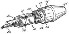
図1には本発明の実施例に係るカテーテルの断面図を模式的に示した。バルーン1を装備した図1に示したカテーテルは血管形成術に広く使用されるタイプのものであるが、ただし本発明は、様々な構造のカテーテルに組み合せて使用し得るものであり、例えば、図6、図7、ないし図8に例示したような種類のカテーテル等と組み合せることによって、小さな体腔の診断用画像を提供し、或いは摘出処置を可能にするものである。一般的な構造のガイド・ワイヤ・ルーメン2及び3を、X線不透過性ガイド・ワイヤ・ルーメン4の外周に嵌合させて接続してあり、このX線不透過性ガイド・ワイヤ・ルーメン4は、通常のカテーテル挿入操作の実行中にカテーテル・ガイド・ワイヤを挿通しておくための中央孔6を形成している。エポキシ材料製の封止材8が、電子回路ボディ12とトランスデューサ・アセンブリ14とから成る画像形成デバイス10を、カテーテル・シャフト16の端部に固定している。本発明に係る画像形成デバイス10はマルチセクション型ボディを備えており、このマルチセクション型ボディは、互いに分離した、そして互いに異なった材質の、担持部材20のための材料と、トランスデューサ・バッキング材料24として使用するための材料とで構成されている。封止材8は担持部材20に搭載された複数の集積回路(IC)18から成る集積回路一式を保護して絶縁している。本発明の好適実施例に係る図示のバルーン血管形成術用の装置では、画像形成デバイス10は、バルーン1の基端部スリーブ19の中に配設されている。 FIG. 1 schematically shows a cross-sectional view of a catheter according to an embodiment of the present invention. The catheter shown in FIG. 1 equipped with the balloon 1 is of a type widely used in angioplasty, however, the present invention can be used in combination with catheters of various structures. 6, a diagnostic image of a small body cavity is provided or combined with a catheter or the like of the type illustrated in FIG. 7 or FIG.
トランスデューサ・アセンブリ14については後に図3を参照しつつ更に詳細に説明するが、ここでその概要を説明しておくと、このトランスデューサ・アセンブリ14は、複数のトランスデューサ・エレメント22から成るトランスデューサ・エレメント集合を備えている。トランスデューサ・エレメント22は、バッキング材料24を芯にして、その周囲に、円筒形状の配列形態で支持されている。ただし、トランスデューサ・デバイスの分野の当業者であれば、本明細書の記載と慣用技術とに基づいて、これ以外のトランスデューサ・エレメントの配列形態にも想到することであろう。 The
更に図1を参照して説明を続けると、バルーン1は画像形成デバイス10に近接して位置しており、このバルーン1のカテーテル・シャフト16及びルーメン3と夫々に結合している両端部を一般的な方式で気密封止して、このバルーン1の内部を外部環境から隔絶させている。封止材8の中には細管26を埋め込んであり、この細管26は、バルーン1の内部とバルーン膨張源との間で流体を流通させるためのものである。バルーン1の膨張可能な部分の中に、ルーメン3に取付けたX線不透過性のマーカー・バンド27が収容されており、このマーカー・バンド27によって、X線蛍光透視装置上でのカテーテルの位置確認を容易にしている。 Still referring to FIG. 1, the balloon 1 is positioned in proximity to the
複数本の内側導線と複数本の外側導線とを1本にまとめたケーブル28によって、複数のIC18と制御ステーションのコンピュータとの間で、データ信号や制御信号等の電気信号を伝達するようにしている。ケーブル28の中の内側導線は、その各々が、絶縁被膜で保護された単線の導体で形成されている。一方、外側導線はケーブル28の周囲に螺旋状に巻回されており、ケーブル28の内側導線が伝達している信号を遮蔽している。このケーブルは絶縁材料で被覆したものとすることが好ましい。 An electrical signal such as a data signal or a control signal is transmitted between the plurality of
次に図2について説明する。同図は、別々に構成した電子回路ボディ12とトランスデューサ・アセンブリ14との間の信号経路を接続する以前の、途中まで組立てた状態にある診断用画像形成カテーテル10の先端部を示しており、この状態を図示したのは、トランスデューサ・アセンブリ14と電子回路ボディ12とから成る画像形成デバイス10の明確に分離した第1部分と第2部分とを明示すためである。同図では、画像形成デバイス10の説明を分かり易くするために画像形成デバイス10を覆う基端部スリーブ19とエポキシ材料製の封止材8とを除去して、複数個の集積回路チップ18とそれらに付随する電子回路配線部分とを露出させてある。ノーズコーン25は、超音波画像形成カテーテルの先端部を丸みの付いた形状にして、この超音波画像形成カテーテルを血管内に入れて行くときに、血管を傷つけないようにするためのものである。 Next, FIG. 2 will be described. The figure shows the distal end portion of the
X線不透過性ガイド・ワイヤ・ルーメン4は、X線蛍光透視装置を使用することによって、患者の体内における位置を視認することができるため、カテーテルの位置の確認を助ける。このX線不透過性ガイド・ワイヤ・ルーメン4は更に、電子回路ボディ12とトランスデューサ・アセンブリ14との両方を支持している。X線不透過性ガイド・ワイヤ・ルーメン4の外径は約0.5mmである。X線不透過性ガイド・ワイヤ・ルーメン4は更に別の機能も果たしており、それは、電子回路ボディ12とトランスデューサ・アセンブリ14とを精密に位置合せするためのガイド部材としての機能であり、それらを精密な位置合せする必要があるのは、図3に示したように、電子回路ボディ12上に取付けた複数のIC18からの64本の導体ライン30の夫々をトランスデューサ・アセンブリ14に設けた64個のトランスデューサ接点32の夫々に位置合せするためである。X線不透過性ガイド・ワイヤ・ルーメン4によって、画像形成デバイス10の構成要素である電子回路ボディ12とトランスデューサ・アセンブリ14との間の位置合せが容易にできるようにするためには、X線不透過性ガイド・ワイヤ・ルーメン4と、担持部材20及びバッキング材料24との、いずれとの間の間隙も、約25ミクロン以下にしておかねばならない。それらとの間の間隙をこの程度に小さくしておけば、複数本の導体ライン30と複数個のトランスデューサ接点32との間の、半径方向における適切な位置合せが確実に行なわれる。 The radiopaque
IC18を担持部材20上に物理的に取付けるために、それら4個のIC18を半導体チップの製造の分野の当業者には周知の反転形チップ構造にして、担持部材20上に形成されている複数の導電用パッド34から成る導電用パッド集合にボンディングするようにしてある。それら導電用パッド34は、互いに近接している複数個のICチップ18を、それらICチップどうしの間で相互接続すると共に、それらIC18とケーブル28との間を接続する機能も果たしており、ケーブル28はそれらIC18を、患者の体外に設置されている信号処理装置に信号伝達可能に接続している。導電用パッド34は更に、複数のIC18を前述の複数本の導体ライン30に接続している。それら導体ライン30は複数のIC18を、トランスデューサ・アセンブリ14の中のトランスデューサ・エレメントを画成している64個の電極から成る電極集合に結合している。 In order to physically mount the
4個のIC18は各々が16本ずつのチャネルを備えており、それら16本のチャネルは、トランスデューサ・アセンブリ14の中の16個のトランスデューサ電極によって画成されている16個のトランスデューサ・エレメントに対応している。4個のIC18は、その各々が、導体ライン30によってトランスデューサ・アセンブリ14の中の対応するトランスデューサ・エレメントに結合されているそのICの16本のチャネルのうちの1本ないし複数本のチャネル上に、超音波周波数領域の電気信号をシーケンシャルに送信及び受信する機能を備えている。また、4個のIC18は、信号処理装置が送出する励振パルスを1個ないし複数個のトランスデューサ・エレメントへ分配するマルチプレクシングの機能も備えている。いかなる時点でも、各IC18の16本のチャネルのうちの1本ないし複数本のチャネルが、励振信号で励振することができるか、または、IC18に格納されている起動制御信号を使用することによって反射波即ちエコーを受信することができる状態におかれている。アクティブなトランスデューサ・エレメントへ入射した反射波から生成された電気信号は、増幅された後に伝送ケーブル28の中の電線を介して外部の信号処理装置へ送信される。 The four
次に図3について説明する。同図は、図1のカテーテルの画像形成部の詳細な側面断面図であり、画像形成デバイス10の構造と材料とを示すために描いた図である。同図には、電子回路ボディ12及びトランスデューサ・アセンブリ14を、それらを組合せた状態で図示してあり、これは、それらが画像形成カテーテルの完成した構造の中で存在している状態に他ならない。トランスデューサ・アセンブリの夫々の層は、図3にも詳細に示してあるが、ただし、トランスデューサ・アセンブリ14の円環状の層について説明している間は、図2の4−4線に沿ったトランスデューサ・アセンブリの断面図である図4を参照するのが良いであろう。 Next, FIG. 3 will be described. 1 is a detailed side cross-sectional view of the image forming portion of the catheter of FIG. 1 and is a view drawn to show the structure and materials of the
担持部材20は、接着剤層36によってX線不透過性ガイド・ワイヤ・ルーメン4に接着されており、この接着剤層36には、市販の様々な医療用シアノアクリレートエポキシのうちの任意のものを使用することができる。電子回路ボディ12が充分に固定できさえすれば、接着剤層36に替えて、任意の固定材料ないし固定構造を採用しても構わない。既述の如く、接着剤層36が充填されているX線不透過性ガイド・ワイヤ・ルーメン4と担持部材20との間の間隙は、X線不透過性ガイド・ワイヤ・ルーメン4が、電子回路ボディ12とトランスデューサ・アセンブリ14との間の電気的接点を位置合せするのを補助することができるように、非常に小さくしておく必要がある。 The
本発明の好適実施例における担持部材20は、熱膨張率が小さく剛性と強度が大きい材料で形成されている。担持部材20は200℃以上の温度に耐える耐熱性を備えている必要があり、この200℃という温度は、複数個のIC18から成るIC一式を担持部材20に接続するボンディング工程において電子回路ボディ12に加わる温度である。更に、超音波カテーテルの操作時にIC18それ自体が発生する熱によって担持部材20が膨張するおそれもある。このときの担持部材20の熱膨張量が余りに大きいと、担持部材20から導電用パッド34に加わる剪断力のためにIC18の接点と導体ライン30との間の電気接続に障害が発生するおそれが無視できない。酸化アルミニウム(Al2O3 )は、以上に述べた、担持部材20のための材料に求められる望ましい特性を備えている。ただし、ハイブリッド回路の分野の当業者であれば、酸化アルミニウムに替わるその他の様々な適当な材料にも想到することであろう。酸化アルミニウムは更に、音響インピーダンス非常に大きく(約40MRayls)、損失が比較的小さいという特性を有する。以下に説明するように、酸化アルミニウムは、これらの音響学的特性を有するため、高感度トランスデューサ・エレメントに関連して使用するトランスデューサ・バッキング材料の候補としては、良いものではない。The
封止材8を電子回路ボディ12の外周表面に被着してあるのは、カテーテル・アセンブリの形状をより円筒形に近くすることと、電子回路を絶縁することとを目的としたものである。封止材8には、一般的に、市販の様々な医用紫外線硬化性アクリル樹脂のうちの任意のものを使用することができる。血液による汚染や万一の電気ショックからの保護のために、電子回路ボディ12の表面を保護層で覆うようにしても良い。保護層の材料には、例えばパリレーン(parylene)等を用いることができる。超音波カテーテルをはじめとする、体内に挿入する医用機器の分野の当業者ならば、この保護層に用いるのに適当なその他の様々な材料にも想到することであろう。保護層は、図1に示したバルーン血管形成術用カテーテルでは基端部スリーブ19で構成されており、また、図6に示したような診断用画像形成カテーテルの場合には鞘体38で構成すれば良い。 The reason why the sealing
次に、トランスデューサ・アセンブリ14とそれに関連した構造部分とについて説明する。トランスデューサ・アセンブリ14のバッキング材料24は、音響インピーダンスが比較的小さく(<10MRayls)、損失係数が大きい(約20〜40dB/mm )という特性を有する材料で形成することが好ましい。これらの特性が必要とされるのは、トランスデューサ材料40としてPZT組成物等の高感度トランスデューサ材料を使用した場合であり、この場合には、バッキング材料に音響インピーダンスが大きく損失の少ない材料を使用したならば、それによって発生するリンギング現象のために、そのトランスデューサ材料のせっかくの優れた信号感度が台無しになってしまう。この理由から、酸化アルミニウムはトランスデューサ・アセンブリ14のバッキング材料24には不適当な材料である。そのため本発明の超音波カテーテルでは、バッキング材料24を別体の部材とし、異なった材料を使用している。バッキング材料24の好適な材料には、例えば、ゴム粒子または微小ガラス球体を混練したエポキシ樹脂がある。この種の樹脂の具体例としては、米国、コネチカット州、トーリントンに所在の Dymax Corp.社の「"light-weld" 183-M」がある。超音波画像形成の分野の当業者であれば、音響インピーダンスが小さく損失が大きい、その他の様々な適当な材料にも想到することであろう。空気も理想的なバッキング材料ではあるが、実際問題として、空気バッキング方式のトランスデューサ・アセンブリは製作が困難である。 Next, the
従って、本発明の超音波カテーテルの特徴の1つは、画像形成デバイス10を構成している担持部材とバッキング材料とを別体の部材とし、担持部材の材料とバッキング材料とに、互いに非常に対照的な特性を有する、異なった材質の材料を使用していることにある。2種類の明らかに異なった材料を用いることによって、電子回路ボディ12の必要条件とトランスデューサ・アセンブリ14の必要条件という、互いに異なった必要条件を共に満足する、構造上及び音響上の望ましい特性が得られている。 Accordingly, one of the features of the ultrasonic catheter of the present invention is that the carrier member and the backing material constituting the
トランスデューサ・アセンブリ14を製作するための好適な方法について説明すると、先ず、トランスデューサ・アセンブリ14の複数の外層を夫々個別に、平らなシートとして製造する。それらの層には、64個の導電用電極42から成る第1導電用電極集合と、トランスデューサ材料40と、連続した1枚の層である導電用電極44と、整合層46とが含まれている。それらの層を個別に製作したならば、続いて、複数のトランスデューサ・エレメント22を形成した平らなシートをバッキング材料24の周囲に巻き付けて、接着剤層48で接着する。トランスデューサ・アセンブリ14の機械的及び音響的な特性によっては、複数のトランスデューサ・エレメント22を物理的に分離させておくことが望まれる場合がある。この場合、複数のトランスデューサ・エレメント22の各々が均一に配置されていることが望ましいため、バッキング材料24を、その外径寸法が非常に小さな公差の中に収まるように製造することによって、複数のトランスデューサ・エレメント22を形成した平らなシートをそのバッキング材料24の外周に巻き付けて両端を合わせて円筒形状にしたときに、そのシートの両端縁の間の間隙または重なり部ができる限り小さくなるようにする必要がある。或いは別法として、平面形状のトランスデューサ・アセンブリ14を丸めて正確な外径寸法を有する円筒形状にし、これをX線不透過性ルーメン4に対して同心となるように保持した上で、そのルーメン4とトランスデューサ・アセンブリ14との間の間隙にバッキング材料24を充填するという方法を用いても良い。この方法を用いれば、巻き付けて円筒形にする平らなシートの両端のトランスデューサ・アレイ・エレメントどうしの間の間隔を確実にその他のトランスデューサ・アレイ・エレメントどうしの間の間隔と同一に揃えることができる。このトランスデューサ・シートをルーメン4の周囲に巻き付けたときの円周方向の寸法誤差は±8ミクロン以下にすべきであろう。更に、電子回路ボディ12とトランスデューサ・アセンブリ14との間で、それらの電気接点どうしの位置合せを容易にするためには、バッキング材料24の内径寸法を、X線不透過性ガイド・ワイヤ・ルーメン4の外径寸法に非常に近くしておく必要がある。トランスデューサ・アセンブリ14の、以上に説明した複数の層から成る同心環状構造を、図1の4−4線に沿ったトランスデューサの断面を示した図4に模式的に示した。 A preferred method for fabricating the
以上のようにトランスデューサ・エレメントを平らなシートで製作する方法を採用することによって得られる利点の1つは、トランスデューサ材料40と導電用電極42及び44の各々との間にこれまでは存在していた、静電容量を有する接着剤層をなくし得るということにある。ここで説明している超音波カテーテルに、静電容量を有する接着剤層が以前のように存在していたならば、PZT組成物から成るトランスデューサ材料40の、より高い誘電率に起因する大きなキャパシタンスのために、この好適なトランスデューサ材料の優れた信号感度が損なわれてしまう。 One of the advantages gained by adopting the method of fabricating the transducer element as a flat sheet as described above has heretofore existed between the
このシート方式のトランスデューサ・アレイ製作方法には更に幾つかの利点がある。製作を平らな表面上で行なうことは、湾曲した円筒表面上で行なうより容易である。このことが特に重要であるのは、連続した1枚の導電用電極44の上に、連続したシートの形状ではない、互いに独立した複数のエレメントとしてトランスデューサ材料を形成するために、トランスデューサ材料40を分割しておく必要がある(または切断する必要がある)トランスデューサ・アセンブリの場合である。トランスデューサ材料40を個々に独立した複数のエレメントとして製作できるということは、エレメントどうしの分離を必要とすることのある、クロストークを小さくする(−30dB以下にする)ことが求められている場合に、特定の製作方法を選択する際の重要な要因になる。複数のトランスデューサ・エレメントを形成した平らなシートを製造することのできる会社のうちの幾つかを挙げるならば、次のとおりである。米国、カリフォルニア州、フレモントに所在の Precision Acoustic Devices 社。米国、アリゾナ州、フェニックスに所在の Acoustic Imaging 社。米国、ペンシルベニア州、ルイスタウンに所在の Echo Ultrasound社。フランス国、トゥールに所在の Vermon S.A.社。それに、フランス国、ブザンソンに所在の Imasonic社。 This sheet type transducer array fabrication method has several further advantages. Manufacturing on a flat surface is easier than on a curved cylindrical surface. This is particularly important in order to form the
トランスデューサ・アセンブリ14を形成したのちに、トランスデューサ材料を分極させることが望ましいことがあり、その場合には、約5千ボルト程度の高電圧を、第1導電用電極集合を構成している複数の導電用電極42と、連続した1枚の導電用電極44との間に印加することによって分極させる。従って、この分極処理は、トランスデューサ・アセンブリ14が、電子回路ボディ12から分離して、独立したアセンブリの状態であるうちに実行することが望ましく、なぜならば、もしそのような高電圧がIC18に加わったならば、IC18の電子回路が破壊されてしまうからである。 After forming the
接着剤層48はバッキング材料24を、第1導電用電極集合を構成している複数の導電用電極42に接着しており、それら複数の導電用電極42はバッキング材料24の外周に均一間隔で並んでいる。第1導電用電極集合を構成している複数の導電用電極42は、トランスデューサ・アレイの中の個々のトランスデューサ・エレメントを画成している。第1導電用電極集合を構成している複数の導電用電極集合42は、トランスデューサ接点集合を構成している64個のトランスデューサ接点32に接続している。夫々が1つずつのトランスデューサ・エレメントに対応した複数のトランスデューサ接点32の各々を、接続材料50が、複数本の導体ライン30のうちの対応した1本の導電ラインに電気的に接続しており、これによって、トランスデューサ・エレメント22とIC18との間の電気信号経路が画成されている。接続材料50には、銀または金を含有したエポキシ・ドロップレット、はんだバンプ、金バンプ、はんだテープ等をはじめとする、幾つもの公知の適当な導体材料のうちの任意のものを使用することができる。 The adhesive layer 48 adheres the
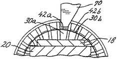
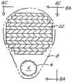
複数の導電用電極42を複数本の導体ライン30に接続するための接続方法には、以上の他にも幾つかの方法がある。図5A及び図5Bは、トランスデューサ・アセンブリ14の銅製の複数本の導電用電極42を、バッキング材料24及びトランスデューサ材料40から突出させた、別実施例の超音波カテーテルを模式的に示している。1本の導電用電極42のうちの、バッキング材料24から突出している部分は、トランスデューサ・アセンブリ14を電子回路ボディ12に接続したときに対応する導体ライン30の上に重なるため、公知のギャップ・ウェルダを用いて個々の導体ライン30を夫々に対応する導電用電極42に融着することができる。 In addition to the above, there are several methods for connecting the plurality of
図5Aは、途中まで組み立てた状態の超音波カテーテルの断面図であり、上述の接続方法を説明するための図である。ギャップ・ウェルダを用いることによって、図3に示したはんだ材料の個々のドロップレット50を形成する必要をなくすことができる。はんだドロップレットが不要になれば、電子回路部品担持部材20の構造を簡単化し得る可能性があり、なぜならば、はんだドロップレットを形成する場合には、導体ライン30とトランスデューサ接点32とを融着するためのドロップレットを適切に形成できるように、担持部材20のトランスデューサ・アセンブリ14側の端面に放射状の溝を形成することが必要になるかも知れないからである。この接続方式のその他の利点としては、導体の接続状態が良好になること、組立方法が簡単化されること、それに、機械的安定性が向上することなどがある。 FIG. 5A is a cross-sectional view of the ultrasonic catheter in a partially assembled state, and is a view for explaining the connection method described above. By using a gap welder, the need to form
図5A及び図5Bに示した接続方式の更に別の利点として、導電用電極42を導体ライン30に結合するボンディング工程を自動化し得ることがある。その場合には図5Bの途中まで組立てた状態の超音波カテーテル・アセンブリの断面図に示したように、先ず複数本の導体ライン30と複数本の導電用電極42とを位置合せする。続いてギャップ・ウェルダの先端部70を、位置合せした複数組の導体ライン及び導電用電極のうちの1組の上に降ろす。先端部70は導電用電極42aをそれに対応した導体ライン30aの上に押し付ける。先端部70の2つの電極の間に低電圧の大きな電流を流す。この電流によって導電用電極42aが導体ライン30aに融着する。続いて、カテーテル・アセンブリを回転させて、その次の、互いに位置合せされている導電用電極と導体ラインとの組(42b及び30b)を先端部70の直下に位置させて融着操作を再度実行する。この融着操作を次々と連続して行ない、全ての導電用電極と導体ラインとの融着を完了する。 Yet another advantage of the connection scheme shown in FIGS. 5A and 5B is that the bonding process for coupling the
次に再び図3の超音波画像形成デバイスについて説明する。メガヘルツの単位の周波数領域で電気エネルギから音響エネルギへの変換、及びその逆の変換を行なうために使用することのできる好適なトランスデューサ材料には様々な種類のものがある。本発明の好適実施例に関しては、結合係数kt の値で表わされるトランスデューサ材料の効率が高く(50%以上)、帯域幅が広くなければならず(中心周波数の50%以上)、複数のトランスデューサ・エレメントが互いに良好に整合していなければならず、挿入損失が小さくなければならず(−40dB以下)、更に、中心周波数が略々20MHz の付近になければならない。そのため、本発明の好適実施例では、トランスデューサ材料24に、公知の様々な適当なPZT組成物のうちの任意のものを使用するようにしている。PZT組成物の物性についての要約が、「Acoustic Waves: Devices, Imaging, and Analog Signal Processing, by Professor Gordon S. Kino, Prentice-Hall, Inc., 1987」という文献の第554〜第555頁に掲載されている。一般的にこの種の組成物は、75℃以上の温度にさらされると損なわれるおそれがあり、従って、IC18を担持部材20に接続するボンディング工程を実行する時点では、その場に存在していないようにすべきである。Next, the ultrasonic image forming device of FIG. 3 will be described again. There are various types of suitable transducer materials that can be used to convert electrical energy to acoustic energy and vice versa in the frequency range of the megahertz unit. For the preferred embodiment of the present invention, the transducer material represented by the value of the coupling coefficient kt must be highly efficient (greater than 50%), wide in bandwidth (greater than 50% of the center frequency), The elements must be well matched to each other, the insertion loss must be small (−40 dB or less), and the center frequency should be approximately in the vicinity of 20 MHz. As such, the preferred embodiment of the present invention employs any of a variety of known suitable PZT compositions for the
トランスデューサ層40の径方向の厚さは、超音波カテーテルの指定の中心動作周波数の波長の2分の1(半波長)の厚さか、或いは、半波長の奇数倍の厚さにすることが好ましい。「Biomedical Ultrasonics」という文献の第53頁に説明されているように、そのような厚さとすることによって、そのトランスデューサを超音波カテーテルの中心動作周波数に共振させることが可能になる。本発明の好適実施例では、トランスデューサ材料24の径方向の厚さを約0.1mmにしている。The radial thickness of the
PZT組成物を用いることによって得られる、トランスデューサの優れた信号感度を充分に利用するためには、バッキング材料24の音響インピーダンスが小さくなければならない。従って、音響インピーダンスが大きい酸化アルミニウムで形成されている担持部材20は、バッキング材料24として使用すべきではない。そこで、従来そうであった、電子回路ボディ12とトランスデューサ・アセンブリ14とを共に支持する単一部材として形成した担持部材に替えて、担持部材のセクション20と、バッキング材料のセクション24とを分離した構造を採用している。 In order to take full advantage of the superior signal sensitivity of the transducer obtained by using the PZT composition, the acoustic impedance of the
トランスデューサ材料40の外周表面を覆っている連続した1枚の導電用電極44をトランスデューサ・エレメント22にとってのグラウンド面にしてある。この導電用電極44は、整合層46の表面にスパッタリングによって金を被着して形成した層とすることが好ましい。ただし、トランスデューサ製造の分野の当業者であれば、その他の適当な導体材料及び導体の被着形成方法にも想到することであろう。また、この超音波カテーテルを適切に動作させるために不可欠というのではないが、連続導電用電極44は、ケーブル28が提供しているグラウンド線に公知の方法で接続しておくことが好ましい。このグラウンド線は、電子回路部品担持部材20に沿って延在させておき、電子回路ボディ12とトランスデューサ・アセンブリ14とを連結した後に、連続導電用電極44に接続すれば良い。グラウンド線を接続するための考えられる方法の1つが、故 Proudian 他の米国特許第4917097号の図2に示されている。 A continuous
複数のトランスデューサ・エレメント22は、整合層46によって覆われている。「Biomedical Ultrasonics, by P.N.T. Wells, Academic Press 1977」という文献の第54頁に説明されているように、負荷の中への伝送の効率は、4分の1波長の厚さのインピーダンス整合層を用いることによって、向上させることができる。現時点で好適と考えられている実施例においては、整合層46を、厚さが約0.06mmの、充填剤を混練したエポキシから成る層にしている。超音波画像形成の分野の当業者であれば、これ以外の適当な整合層の材料やそのその厚さにも容易に想到することであろう。The plurality of
電子回路ボディ12とトランスデューサ・アセンブリ14とを別々に組立てたならば、続いて接着剤層52でそれらを互いに接着し、そして先に説明した方法で、それら電子回路ボディ12とトランスデューサ・アセンブリ14との間の電気的接続を行なう。更に、超音波カテーテルのための信号処理装置(これについては既に Proudian et al.の米国特許第4917097号に記載されている)に接続しているリード線を包含しているケーブル28を、公知の方法を用いて担持部材20上の導電用パッド34に接続する。 Once the
図6は、バルーン1を備えていない診断用画像形成カテーテルの中に画像形成デバイス10を装備した本発明の別実施例を示している。同図は、診断用画像形成カテーテルの幾つかの部分を除去して、ケーブル28とルーメン2とが見えるように描いてある。この図6に示した画像形成カテーテルはバルーン1を備えていないため、バルーンの内部へ流体を出し入れするための細管26は言うまでもなく装備されていない。ただし、この画像形成カテーテルにはノーズコーン25を嵌装してある。ノーズコーン25は、この超音波画像形成カテーテルの先端部を丸みの付いたものにして、このカテーテルを体腔内に挿入するときに、体腔の内壁を傷付けることがないようにしている。鞘体38がエポキシ樹脂8を覆っており、これによって、患者の血液による汚染や万一の電気ショックから防護している。鞘体38はパリレーン等の材料で製作することが好ましいが、体腔内に挿入する医用機器の分野の当業者であればパリレーンに替わるその他の適当な材料にも容易に想到することであろう。図6に示した画像形成カテーテルの構造は、以上に述べた以外の部分については、図1のバルーン血管形成術用超音波画像形成カテーテルの構造と変わるところはない。 FIG. 6 shows another embodiment of the present invention in which the
先に説明した本発明の好適実施例に備えたトランスデューサ・アレイの配列形態は、円筒形状のコアの周囲に円筒形状に配列したものであったが、本発明を実施する超音波カテーテルにおける配列形態には、これ以外にも多くの配列形態がある。それら配列形態の具体的な例を図7及び図8に示した。ただし当業者であれば、本明細書中の本発明の説明に基づいて、超音波カテーテルのトランスデューサ・アレイの更に別の配列形態にも想到することであろう。 The arrangement form of the transducer array provided in the above-described preferred embodiment of the present invention was arranged in a cylindrical shape around the cylindrical core, but the arrangement form in the ultrasonic catheter embodying the present invention. There are many other arrangement forms. Specific examples of these arrangement forms are shown in FIGS. However, one of ordinary skill in the art will also appreciate other arrangements of ultrasound catheter transducer arrays based on the description of the invention herein.
図7A及び図7Bは、側方視型のリニア・アレイを用いた画像形成カテーテルの断面側面図及び横断面図である。この画像形成カテーテルの構成では、複数のトランスデューサ・エレメント22を1つの平面上に並べ、画像形成カテーテルの挿入方向に対して直角な方向に並べて配列してある。この配列形態によれば、体腔の長手方向に沿った画像が得られる。本発明のこの別実施例でもIC18とケーブル28との間の接続は、本発明の先に説明した実施例と同様にしてある。更に、本発明に従って、IC18を電子回路部品担持部材20に搭載してあり、この電子回路部品担持部材20は、図1に示した本発明の好適実施例に関連して先に説明したものと同タイプのものである。IC18は導体ライン30を介してトランスデューサ・エレメント22に電気的に結合されている。この実施例では封止材8がトランスデューサ・エレメント22のためのバッキング材料を兼ねている。 7A and 7B are a sectional side view and a transverse sectional view of an imaging catheter using a side-viewing linear array. In this imaging catheter configuration, a plurality of
図8A、図8B、及び図8Cは、図1に示した前方視型の「先端発射形」画像形成カテーテルの断面側面図、断面正面図、及び断面平面図である。これらの、図8A、図8B、及び図8Cは、トランスデューサ22のためのバッキング材料を兼ねている封止材8を部分的に除去して、電子回路の部分の配設位置と姿勢とが見えるように描いてある。トランスデューサ・エレメント22は、その配列形態をプレーナ・アレイ(平面状アレイ)として、カテーテルの正面に取付けてある。また、ガイド・ワイヤ・ルーメン4を、超音波画像形成デバイス10に隣接させて取付けてある。このガイド・ワイヤ・ルーメン4の直径は約0.3mmであり、これはこの画像形成カテーテルの直径の約3分の1である。 8A, 8B, and 8C are a cross-sectional side view, a cross-sectional front view, and a cross-sectional plan view of the forward-viewing “tip firing” imaging catheter shown in FIG. 8A, 8B, and 8C, the sealing
この構成によれば、体腔内の前方視野が画像として得られる。その視野の大きさは、アレイの大きさと、エレメントの個数と、個々のエレメントの寸法と、周波数とによって決まる。本発明のこの別実施例でもIC18とケーブル28との間の接続は、本発明の先に説明した実施例と同様にしてある。更に、本発明に従って、IC18を担持部材20に搭載してあり、この担持部材20は、図1に示した本発明の好適実施例に関連して先に説明したものと同タイプのものである。IC18は導体ライン30を介してトランスデューサ・エレメント22に電気的に結合されている。封止材8がトランスデューサ・エレメント22のためのバッキング材料を兼ねるようにしても良い。 According to this structure, the front visual field in a body cavity is obtained as an image. The size of the field of view depends on the size of the array, the number of elements, the dimensions of the individual elements, and the frequency. In this alternative embodiment of the invention, the connection between the
当業者には容易に理解されるように、以上の好適実施例に対しては、その様々な点に変更を加えることが可能である。本発明は、添付の請求項に明確に記載した通りのものである。本発明の概念並びに範囲は、本願の教示を知悉した当業者が想到し得るであろう好適実施例に対する変更ないし改変をも包含するものである。 As will be readily appreciated by those skilled in the art, various changes may be made to the preferred embodiment described above. The invention is as specifically set forth in the appended claims. The concept and scope of the present invention also encompasses changes and modifications to the preferred embodiment that would occur to those skilled in the art with knowledge of the teachings herein.
12 電子回路ボディ
14 トランスデューサ・アセンブリ
18 IC
20 担持部材
22 トランスデューサ・エレメント
24 バッキング材料
42 導電用電極
44 導電用電極
46 整合層12
20 Supporting
Claims (22)
Translated fromJapaneseトランスデューサ・アレイと集積回路とを別々に支持する、材質が異なる複数のセクションを有するマルチセクション形ボディであって、トランスデューサのバッキングとして機能し第2セクションと比べて大きな音響エネルギ吸収率を有する第1材料から成る第1セクションと、集積電子回路要素を支持するための第2材料から成る第2セクションと、を含んでいるマルチセクション形ボディと、
前記マルチセクション形ボディの前記第1セクションに取付けられたトランスデューサ・アセンブリであって、前記トランスデューサ・アレイを含んでおり、該トランスデューサ・アレイは、脈管内へ超音波を発信して、該超音波の超音波エコーに応じて第1電気信号を生成するものである、トランスデューサ・アセンブリと、
前記マルチセクション形ボディの前記第2セクションに取付けられた電気信号変換用集積回路要素であって、前記トランスデューサ・アセンブリから前記第1電気信号を受け取り、該第1電気信号を第2電気信号に変換し、そして、該第2電気信号を、該第2電気信号を伝送するための少なくとも1本の信号チャネルを含んでいるケーブルを介して、脈管の外部の環境へ送出する、電気信号変換用集積回路要素と、
前記第1電気信号を前記トランスデューサ・アレイから前記電気信号変換用集積回路要素へ伝達する、前記トランスデューサ・アレイと前記電気信号変換用集積回路要素との間の複数の電気伝送経路と、
を備えたことを特徴とする超音波カテーテル・プローブ。In an ultrasonic catheter / probe used by being inserted into a vascular vessel that emits an ultrasonic wave and provides a converted electric signal generated from an ultrasonic echo of the emitted ultrasonic wave.
A multi-section body having a plurality of sections made of different materials and supporting a transducer array and an integrated circuit separately, and functions as a transducer backing and has a large acoustic energy absorption rate compared to the second section. A multi-section body including a first section of material and a second section of second material for supporting an integrated electronic circuit element;
A transducer assembly attached to the first section of the multi-section body including the transducer array, the transducer array transmitting ultrasonic waves into a vessel, A transducer assembly for generating a first electrical signal in response to an ultrasonic echo;
An integrated circuit element for electrical signal conversion attached to the second section of the multi-section body that receives the first electrical signal from the transducer assembly and converts the first electrical signal to a second electrical signal And transmitting the second electrical signal to an environment outside the vessel via a cable including at least one signal channel for transmitting the second electrical signal. An integrated circuit element;
A plurality of electrical transmission paths between the transducer array and the electrical signal converting integrated circuit element for transmitting the first electrical signal from the transducer array to the electrical signal converting integrated circuit element;
An ultrasonic catheter probe characterized by comprising:
少なくとも1本のルーメンを内蔵しているシャフトと、
前記シャフトに取付けた超音波プローブと、
を備えており、
前記超音波プローブが、
トランスデューサ・アレイと集積回路とを別々に支持する互いに材質の異なった複数のセクションを有するマルチセクション形ボディであって、トランスデューサのバッキングとして機能し第2セクションと比べて大きな音響エネルギ吸収率を有する第1材料から成る第1セクションと、集積回路を支持するための第2材料から成る第2セクションとを含んでいるマルチセクション形ボディと、
前記マルチセクション形ボディの前記第1セクションに取付けられたトランスデューサ・アセンブリであって、前記トランスデューサ・アレイを含んでおり、該トランスデューサ・アレイは、脈管内へ超音波を送信して、その送信した超音波の超音波エコーに応じて第1電気信号を生成するものである、トランスデューサ・アセンブリと、
前記マルチセクション形ボディの前記第2セクションに取付けられた電気信号変換用集積回路要素であって、前記トランスデューサ・アセンブリから前記第1電気信号を受け取り、該第1電気信号を第2電気信号に変換し、そして、該第2電気信号を、該第2電気信号を伝送するための少なくとも1本の信号チャネルを含んでいるケーブルを介して、脈管の外部の環境へ送出する、電気信号変換用集積回路要素と、
前記第1電気信号を前記トランスデューサ・アレイから前記電気信号変換用集積回路要素へ伝達する、前記トランスデューサ・アレイと前記電気信号変換用集積回路要素との間の複数の電気伝送経路と、
を備えた画像形成デバイスである、
ことを特徴とする超音波画像形成カテーテル。In an ultrasound imaging catheter for use in insertion into a vessel that emits ultrasound and provides a converted electrical signal resulting from an ultrasound echo of the emitted ultrasound,
A shaft containing at least one lumen;
An ultrasonic probe attached to the shaft;
With
The ultrasonic probe is
A multi-section body having a plurality of sections made of different materials that separately support a transducer array and an integrated circuit, and functions as a transducer backing and has a large acoustic energy absorption rate compared to the second section. A multi-section body including a first section made of one material and a second section made of a second material for supporting an integrated circuit;
A transducer assembly attached to the first section of the multi-section body including the transducer array, the transducer array transmitting ultrasonic waves into a vessel and transmitting the transmitted ultrasound A transducer assembly that generates a first electrical signal in response to an ultrasonic echo of the sound wave;
An integrated circuit element for electrical signal conversion attached to the second section of the multi-section body that receives the first electrical signal from the transducer assembly and converts the first electrical signal to a second electrical signal And transmitting the second electrical signal to an environment outside the vessel via a cable including at least one signal channel for transmitting the second electrical signal. An integrated circuit element;
A plurality of electrical transmission paths between the transducer array and the electrical signal converting integrated circuit element for transmitting the first electrical signal from the transducer array to the electrical signal converting integrated circuit element;
An image forming device comprising:
An ultrasound imaging catheter characterized by the above.
前記トランスデューサ・アレイを含んでいるトランスデューサ・アセンブリを前記マルチセクション形ボディの前記第1セクションに取付けるトランスデューサ・アセンブリ取付ステップであって、前記トランスデューサ・アレイは、脈管内へ超音波を送信して、その送信した超音波の超音波エコーに応じて第1電気信号を生成するものであり、該トランスデューサ・アセンブリは、複数のトランスデューサ接点から成るトランスデューサ接点集合を含んでおり、それら複数のトランスデューサ接点は、前記トランスデューサ・アレイの複数の導電用電極に結合していると共に前記トランスデューサ・アレイから横方向へ突出している、トランスデューサ・アセンブリ取付ステップと、
電気信号変換用集積回路要素を前記マルチセクション形ボディの前記第2セクションに取付ける電気信号変換用集積回路要素取付ステップであって、該電気信号変換用集積回路要素は、前記トランスデューサ・アレイから前記第1電気信号を受け取って該第1電気信号を第2電気信号に変換し、該第2電気信号がケーブルを介して伝送されるようにしてあり、該ケーブルは前記マルチセクション形ボディを脈管の外部の環境へ接続しており前記第2電気信号を伝送するための少なくとも1本の信号チャネルを備えている、電気信号変換用集積回路要素取付ステップと、
前記第1セクションと前記第2セクションとを隣接した位置に配置して、前記複数のトランスデューサ接点の各々が、前記電気信号変換用集積回路要素に信号伝達可能に接続された複数の導体ラインのうちの対応する1本ずつの導体ラインと重なり合うようにするセクション配置ステップと、
互いに重なり合ったトランスデューサ接点と導体ラインとの組に局所的電流を供給してその組のトランスデューサ接点と導体ラインとを融着させる局所的電流供給ステップと、
を含んでいることを特徴とする超音波脈管内カテーテル・プローブの組立方法。A multi-section body for separately supporting a transducer array and an integrated electronic circuit element, wherein the multi-section body is configured to support a first section composed of a transducer backing and an integrated electronic circuit element. In an assembly method of an ultrasonic intravascular catheter probe having two sections,
A transducer assembly mounting step for mounting a transducer assembly including the transducer array to the first section of the multi-section body, the transducer array transmitting ultrasonic waves into a vessel, and Generating a first electrical signal in response to an ultrasonic echo of the transmitted ultrasonic wave, wherein the transducer assembly includes a set of transducer contacts comprising a plurality of transducer contacts, the plurality of transducer contacts comprising: A transducer assembly mounting step coupled to the plurality of conductive electrodes of the transducer array and projecting laterally from the transducer array;
An electrical signal converting integrated circuit element attaching step for attaching an electrical signal converting integrated circuit element to the second section of the multi-section body, the electrical signal converting integrated circuit element from the transducer array Receiving an electrical signal and converting the first electrical signal into a second electrical signal, wherein the second electrical signal is transmitted over a cable, the cable connecting the multi-section body to the vascular body. Attaching an integrated circuit element for electrical signal conversion, comprising at least one signal channel connected to an external environment and transmitting the second electrical signal;
Of the plurality of conductor lines, the first section and the second section are disposed adjacent to each other, and each of the plurality of transducer contacts is connected to the electric signal converting integrated circuit element so as to transmit a signal. A section placement step to overlap each corresponding conductor line of
Providing a local current to a pair of transducer contacts and conductor lines that overlap each other to fuse the transducer contacts and conductor lines of the set; and
A method for assembling an ultrasonic intravascular catheter probe.
トランスデューサ・アレイと集積電子回路要素とを別々に支持する性質の異なった複数のセクションを有するマルチセクション形ボディであって、トランスデューサのバッキングとして機能し第2セクションと比べて大きな音響エネルギ吸収率を有する第1材料から成る第1セクションと、集積電子回路要素を支持するための第2材料から成る該第2セクションとを含んでいるマルチセクション形ボディと、
前記マルチセクション形ボディの前記第1セクションに支持されたトランスデューサ・アセンブリであって、前記トランスデューサ・アレイを含んでおり、該トランスデューサ・アレイが、脈管内へ超音波を発信して、該超音波の超音波エコーに応じて複数の電気信号を生成する、トランスデューサ・アセンブリと、
前記マルチセクション形ボディの前記第2セクションに支持された集積電子回路要素であって、前記トランスデューサ・アセンブリにより生成された前記電気信号を受信し、該電気信号に応答して前記脈管の外部の環境へ情報を送出する、集積電子回路要素と、
を備えたことを特徴とする超音波カテーテル・プローブ。In an ultrasonic catheter / probe used by being inserted into a vascular vessel that emits an ultrasonic wave and provides a converted electric signal generated from an ultrasonic echo of the emitted ultrasonic wave.
A multi-section body having a plurality of sections with different properties to separately support a transducer array and an integrated electronic circuit element, functioning as a transducer backing and having a higher acoustic energy absorption rate than the second section A multi-section body including a first section of a first material and the second section of a second material for supporting an integrated electronic circuit element;
A transducer assembly supported on the first section of the multi-section body, including the transducer array, the transducer array transmitting ultrasonic waves into a vessel, A transducer assembly that generates a plurality of electrical signals in response to ultrasonic echoes;
An integrated electronic circuit element supported in the second section of the multi-section body that receives the electrical signal generated by the transducer assembly and is external to the vessel in response to the electrical signal. An integrated electronic circuit element that sends information to the environment;
An ultrasonic catheter probe characterized by comprising:
少なくとも1本のルーメンを内蔵しているシャフトと、前記シャフトに取付けた超音波プローブと、を備えており、
前記超音波プローブが、
トランスデューサ・アレイと集積電子回路要素とを別々に支持する性質の異なった複数のセクションを有するマルチセクション形ボディであって、トランスデューサのバッキングとして機能し第2セクションと比べて大きな音響エネルギ吸収率を有する第1材料から成る第1セクションと、集積電子回路要素を支持するための第2材料から成る第2セクションとを含んでいるマルチセクション形ボディと、
前記マルチセクション形ボディの前記第1セクションに支持されたトランスデューサ・アセンブリであって、前記トランスデューサ・アレイを含んでおり、該トランスデューサ・アレイは、脈管内へ超音波を発信して、該超音波の超音波エコーに応じて電気信号を生成するものである、トランスデューサ・アセンブリと、
前記マルチセクション形ボディの前記第2セクションに支持された集積電子回路要素であって、前記トランスデューサ・アセンブリによって生成された前記電気信号を受信し、該電気信号に応答して前記脈管の外部の環境に情報を送出する集積電子回路要素と、
を備えた画像形成デバイスである、
ことを特徴とする超音波画像形成カテーテル。In an ultrasound imaging catheter for use in insertion into a vessel that emits ultrasound and provides an electrical signal converted from the ultrasound echo of the emitted ultrasound,
A shaft containing at least one lumen, and an ultrasonic probe attached to the shaft;
The ultrasonic probe is
A multi-section body having a plurality of sections with different properties to separately support a transducer array and an integrated electronic circuit element, functioning as a transducer backing and having a higher acoustic energy absorption rate than the second section A multi-section body including a first section made of a first material and a second section made of a second material for supporting an integrated electronic circuit element;
A transducer assembly supported on the first section of the multi-section body, the transducer array including the transducer array, which emits ultrasonic waves into the vasculature; A transducer assembly that generates electrical signals in response to ultrasonic echoes;
An integrated electronic circuit element supported in the second section of the multi-section body for receiving the electrical signal generated by the transducer assembly and external to the vessel in response to the electrical signal An integrated electronic circuit element that sends information to the environment; and
An image forming device comprising:
An ultrasound imaging catheter characterized by the above.
前記トランスデューサ・アレイを含んでいるトランスデューサ・アセンブリを前記マルチセクション形ボディの前記第1セクションに取付けるトランスデューサ・アセンブリ取付ステップであって、前記トランスデューサ・アレイは、脈管内へ超音波を発信して、該超音波の超音波エコーに応じて電気信号を生成するものであり、前記トランスデューサ・アセンブリは、複数のトランスデューサ接点から成るトランスデューサ接点集合を含んでおり、それら複数のトランスデューサ接点は、複数の導電用電極に結合していると共に前記トランスデューサ・アレイから横方向へ突出している、トランスデューサ・アセンブリ取付ステップと、
集積電子回路要素を前記マルチセクション形ボディの前記第2セクションに取付ける集積電子回路要素取付ステップであって、該集積電子回路要素は、前記トランスデューサ・アレイによって生成された前記電気信号を受信し、情報を前記脈管の外部の環境へ送出する、集積電子回路要素取付ステップと、
前記第1セクションと前記第2セクションとを隣接した位置に配置して、前記複数のトランスデューサ接点の各々が、前記集積電子回路要素に信号伝達可能に接続された複数の導体ラインのうちの対応する1本ずつの導体ラインと重なり合うようにするセクション配置ステップと、
互いに重なり合ったトランスデューサ接点と導体ラインに局所的電流を供給してトランスデューサ接点と導体ラインとを融着させる局所的電流供給ステップと、
を含んでいることを特徴とする超音波脈管内カテーテル・プローブの組立方法。A multi-section body for separately supporting a transducer array and an integrated electronic circuit element, wherein the multi-section body is configured to support a first section composed of a transducer backing and an integrated electronic circuit element. In an assembly method of an ultrasonic intravascular catheter probe having two sections,
A transducer assembly mounting step of mounting a transducer assembly including the transducer array to the first section of the multi-section body, the transducer array transmitting ultrasonic waves into a vessel, An electrical signal is generated in response to an ultrasonic echo of the ultrasonic wave, and the transducer assembly includes a transducer contact set including a plurality of transducer contacts, and the plurality of transducer contacts includes a plurality of conductive electrodes. A transducer assembly mounting step coupled to and projecting laterally from the transducer array;
An integrated electronic circuit element mounting step for mounting an integrated electronic circuit element to the second section of the multi-section body, the integrated electronic circuit element receiving the electrical signal generated by the transducer array, and information An integrated electronic circuit element mounting step for delivering to the environment outside the vessel;
The first section and the second section are disposed adjacent to each other, and each of the plurality of transducer contacts corresponds to a plurality of conductor lines that are communicatively connected to the integrated electronic circuit element. A section placement step that overlaps one conductor line at a time;
Providing a local current to the transducer contacts and conductor lines that overlap each other to fuse the transducer contacts and conductor lines; and
A method for assembling an ultrasonic intravascular catheter probe.
Applications Claiming Priority (1)
| Application Number | Priority Date | Filing Date | Title |
|---|---|---|---|
| US08/012,251US5368037A (en) | 1993-02-01 | 1993-02-01 | Ultrasound catheter |
Related Parent Applications (1)
| Application Number | Title | Priority Date | Filing Date |
|---|---|---|---|
| JP51804094ADivisionJP3732854B2 (en) | 1993-02-01 | 1994-01-14 | Ultrasound catheter |
Publications (2)
| Publication Number | Publication Date |
|---|---|
| JP2006055649A JP2006055649A (en) | 2006-03-02 |
| JP3831743B2true JP3831743B2 (en) | 2006-10-11 |
Family
ID=21754054
Family Applications (3)
| Application Number | Title | Priority Date | Filing Date |
|---|---|---|---|
| JP51804094AExpired - LifetimeJP3732854B2 (en) | 1993-02-01 | 1994-01-14 | Ultrasound catheter |
| JP2005251525AExpired - LifetimeJP3831743B2 (en) | 1993-02-01 | 2005-08-31 | Ultrasonic catheter / probe |
| JP2005251527APendingJP2005342535A (en) | 1993-02-01 | 2005-08-31 | Ultrasound catheter probe |
Family Applications Before (1)
| Application Number | Title | Priority Date | Filing Date |
|---|---|---|---|
| JP51804094AExpired - LifetimeJP3732854B2 (en) | 1993-02-01 | 1994-01-14 | Ultrasound catheter |
Family Applications After (1)
| Application Number | Title | Priority Date | Filing Date |
|---|---|---|---|
| JP2005251527APendingJP2005342535A (en) | 1993-02-01 | 2005-08-31 | Ultrasound catheter probe |
Country Status (7)
| Country | Link |
|---|---|
| US (1) | US5368037A (en) |
| EP (3) | EP0750883B2 (en) |
| JP (3) | JP3732854B2 (en) |
| AT (3) | ATE236573T1 (en) |
| CA (2) | CA2235947C (en) |
| DE (3) | DE69435314D1 (en) |
| WO (1) | WO1994017734A1 (en) |
Families Citing this family (161)
| Publication number | Priority date | Publication date | Assignee | Title |
|---|---|---|---|---|
| US6029671A (en)* | 1991-07-16 | 2000-02-29 | Heartport, Inc. | System and methods for performing endovascular procedures |
| US5453575A (en)* | 1993-02-01 | 1995-09-26 | Endosonics Corporation | Apparatus and method for detecting blood flow in intravascular ultrasonic imaging |
| US20070016071A1 (en)* | 1993-02-01 | 2007-01-18 | Volcano Corporation | Ultrasound transducer assembly |
| DE69516444T2 (en)* | 1994-03-11 | 2001-01-04 | Intravascular Research Ltd., London | Ultrasonic transducer arrangement and method for its production |
| US5488954A (en)* | 1994-09-09 | 1996-02-06 | Georgia Tech Research Corp. | Ultrasonic transducer and method for using same |
| US5606975A (en)* | 1994-09-19 | 1997-03-04 | The Board Of Trustees Of The Leland Stanford Junior University | Forward viewing ultrasonic imaging catheter |
| US5590658A (en)* | 1995-06-29 | 1997-01-07 | Teratech Corporation | Portable ultrasound imaging system |
| US5957846A (en)* | 1995-06-29 | 1999-09-28 | Teratech Corporation | Portable ultrasound imaging system |
| US7500952B1 (en) | 1995-06-29 | 2009-03-10 | Teratech Corporation | Portable ultrasound imaging system |
| US8241217B2 (en) | 1995-06-29 | 2012-08-14 | Teratech Corporation | Portable ultrasound imaging data |
| US5738100A (en)* | 1995-06-30 | 1998-04-14 | Terumo Kabushiki Kaisha | Ultrasonic imaging catheter |
| US7226417B1 (en)* | 1995-12-26 | 2007-06-05 | Volcano Corporation | High resolution intravascular ultrasound transducer assembly having a flexible substrate |
| US6117083A (en)* | 1996-02-21 | 2000-09-12 | The Whitaker Corporation | Ultrasound imaging probe assembly |
| US6030346A (en)* | 1996-02-21 | 2000-02-29 | The Whitaker Corporation | Ultrasound imaging probe assembly |
| WO1997032277A1 (en)* | 1996-02-29 | 1997-09-04 | Acuson Corporation | Multiple ultrasound image registration system, method and transducer |
| US5733281A (en)* | 1996-03-19 | 1998-03-31 | American Ablation Co., Inc. | Ultrasound and impedance feedback system for use with electrosurgical instruments |
| GB2315020A (en)* | 1996-07-11 | 1998-01-21 | Intravascular Res Ltd | Ultrasonic visualisation catheters |
| US5830145A (en) | 1996-09-20 | 1998-11-03 | Cardiovascular Imaging Systems, Inc. | Enhanced accuracy of three-dimensional intraluminal ultrasound (ILUS) image reconstruction |
| US5857974A (en)* | 1997-01-08 | 1999-01-12 | Endosonics Corporation | High resolution intravascular ultrasound transducer assembly having a flexible substrate |
| USD455210S1 (en) | 1997-01-31 | 2002-04-02 | Acuson Corporation | Ultrasonic transducer assembly controller |
| US5797848A (en)* | 1997-01-31 | 1998-08-25 | Acuson Corporation | Ultrasonic transducer assembly with improved electrical interface |
| US5938616A (en) | 1997-01-31 | 1999-08-17 | Acuson Corporation | Steering mechanism and steering line for a catheter-mounted ultrasonic transducer |
| US5954654A (en)* | 1997-01-31 | 1999-09-21 | Acuson Corporation | Steering mechanism and steering line for a catheter-mounted ultrasonic transducer |
| US6464645B1 (en) | 1997-01-31 | 2002-10-15 | Acuson Corporation | Ultrasonic transducer assembly controller |
| US5846205A (en)* | 1997-01-31 | 1998-12-08 | Acuson Corporation | Catheter-mounted, phased-array ultrasound transducer with improved imaging |
| US5795299A (en)* | 1997-01-31 | 1998-08-18 | Acuson Corporation | Ultrasonic transducer assembly with extended flexible circuits |
| US6045508A (en)* | 1997-02-27 | 2000-04-04 | Acuson Corporation | Ultrasonic probe, system and method for two-dimensional imaging or three-dimensional reconstruction |
| US5876345A (en)* | 1997-02-27 | 1999-03-02 | Acuson Corporation | Ultrasonic catheter, system and method for two dimensional imaging or three-dimensional reconstruction |
| US5921931A (en) | 1997-04-08 | 1999-07-13 | Endosonics Corporation | Method and apparatus for creating a color blood flow image based upon ultrasonic echo signals received by an intravascular ultrasound imaging probe |
| AT407009B (en) | 1997-09-01 | 2000-11-27 | Ali Dr Hassan | CATHETER DEVICE FOR RADIOACTIVE TREATMENT OF BODY CAVES |
| JP3525700B2 (en)* | 1997-09-24 | 2004-05-10 | 富士写真光機株式会社 | Ultrasonic probe |
| US5876344A (en)* | 1997-12-09 | 1999-03-02 | Endosonics Corporation | Modular imaging/treatment catheter assembly and method |
| US20050171478A1 (en)* | 1998-01-13 | 2005-08-04 | Selmon Matthew R. | Catheter system for crossing total occlusions in vasculature |
| USD465024S1 (en) | 1998-01-31 | 2002-10-29 | Acuson Corporation | Ultrasonic transducer assembly controller |
| WO1999058059A1 (en)* | 1998-03-05 | 1999-11-18 | Vardi Gil M | Optical-acoustic imaging device |
| US6440102B1 (en) | 1998-07-23 | 2002-08-27 | Durect Corporation | Fluid transfer and diagnostic system for treating the inner ear |
| US6277077B1 (en) | 1998-11-16 | 2001-08-21 | Cardiac Pathways Corporation | Catheter including ultrasound transducer with emissions attenuation |
| US6306097B1 (en) | 1999-06-17 | 2001-10-23 | Acuson Corporation | Ultrasound imaging catheter guiding assembly with catheter working port |
| US6423002B1 (en) | 1999-06-24 | 2002-07-23 | Acuson Corporation | Intra-operative diagnostic ultrasound multiple-array transducer probe and optional surgical tool |
| US6457365B1 (en)* | 2000-02-09 | 2002-10-01 | Endosonics Corporation | Method and apparatus for ultrasonic imaging |
| US20030060731A1 (en)* | 2001-01-26 | 2003-03-27 | Fleischhacker Mark G. | Non-metallic guide wire |
| US6589182B1 (en) | 2001-02-12 | 2003-07-08 | Acuson Corporation | Medical diagnostic ultrasound catheter with first and second tip portions |
| US7387612B2 (en)* | 2001-03-28 | 2008-06-17 | Cybersonics, Inc. | Floating probe for ultrasonic transducers |
| US6689087B2 (en)* | 2001-03-28 | 2004-02-10 | Cybersonics, Inc. | Floating probe for ultrasonic transducers |
| US6572547B2 (en)* | 2001-07-31 | 2003-06-03 | Koninklijke Philips Electronics N.V. | Transesophageal and transnasal, transesophageal ultrasound imaging systems |
| EP1647232B1 (en) | 2001-12-03 | 2011-08-17 | Ekos Corporation | Catheter with multiple ultrasound radiating members |
| US20040054287A1 (en)* | 2002-08-29 | 2004-03-18 | Stephens Douglas Neil | Ultrasonic imaging devices and methods of fabrication |
| US6712767B2 (en)* | 2002-08-29 | 2004-03-30 | Volcano Therapeutics, Inc. | Ultrasonic imaging devices and methods of fabrication |
| US7245789B2 (en) | 2002-10-07 | 2007-07-17 | Vascular Imaging Corporation | Systems and methods for minimally-invasive optical-acoustic imaging |
| US7527591B2 (en)* | 2003-11-21 | 2009-05-05 | General Electric Company | Ultrasound probe distributed beamformer |
| US7527592B2 (en)* | 2003-11-21 | 2009-05-05 | General Electric Company | Ultrasound probe sub-aperture processing |
| US20050113698A1 (en)* | 2003-11-21 | 2005-05-26 | Kjell Kristoffersen | Ultrasound probe transceiver circuitry |
| EP1738407B1 (en) | 2004-04-20 | 2014-03-26 | Visualsonics Inc. | Arrayed ultrasonic transducer |
| WO2005120360A1 (en)* | 2004-06-10 | 2005-12-22 | Olympus Corporation | Electrostatic capacity type ultrasonic probe device |
| CN1997913A (en)* | 2004-06-29 | 2007-07-11 | 皇家飞利浦电子股份有限公司 | Method and device for medical ultrasound diagnosis |
| US7488288B2 (en)* | 2004-07-29 | 2009-02-10 | Fujinon Corporation | Ultrasonic endoscope |
| US20070005011A1 (en)* | 2005-06-20 | 2007-01-04 | Boston Scientific Scimed, Inc. | Method, system, apparatus, and kit for remote therapeutic delivery |
| EP1952175B1 (en) | 2005-11-02 | 2013-01-09 | Visualsonics, Inc. | Digital transmit beamformer for an arrayed ultrasound transducer system |
| JP4979708B2 (en)* | 2005-11-12 | 2012-07-18 | ボストン サイエンティフィック リミテッド | System for reducing noise in an imaging catheter system |
| US7599588B2 (en) | 2005-11-22 | 2009-10-06 | Vascular Imaging Corporation | Optical imaging probe connector |
| US8303505B2 (en) | 2005-12-02 | 2012-11-06 | Abbott Cardiovascular Systems Inc. | Methods and apparatuses for image guided medical procedures |
| US8840560B2 (en)* | 2006-04-04 | 2014-09-23 | Volcano Corporation | Ultrasound catheter and hand-held device for manipulating a transducer on the catheter's distal end |
| US9867530B2 (en) | 2006-08-14 | 2018-01-16 | Volcano Corporation | Telescopic side port catheter device with imaging system and method for accessing side branch occlusions |
| US10182833B2 (en) | 2007-01-08 | 2019-01-22 | Ekos Corporation | Power parameters for ultrasonic catheter |
| EP2170181B1 (en) | 2007-06-22 | 2014-04-16 | Ekos Corporation | Method and apparatus for treatment of intracranial hemorrhages |
| WO2009009802A1 (en) | 2007-07-12 | 2009-01-15 | Volcano Corporation | Oct-ivus catheter for concurrent luminal imaging |
| US9596993B2 (en) | 2007-07-12 | 2017-03-21 | Volcano Corporation | Automatic calibration systems and methods of use |
| EP2178442B1 (en) | 2007-07-12 | 2017-09-06 | Volcano Corporation | Catheter for in vivo imaging |
| US20090183350A1 (en)* | 2008-01-17 | 2009-07-23 | Wetsco, Inc. | Method for Ultrasound Probe Repair |
| GB2457240B (en) | 2008-02-05 | 2013-04-10 | Fujitsu Ltd | Ultrasound probe device and method of operation |
| US9184369B2 (en) | 2008-09-18 | 2015-11-10 | Fujifilm Sonosite, Inc. | Methods for manufacturing ultrasound transducers and other components |
| EP2345066B1 (en) | 2008-09-18 | 2018-10-31 | FUJIFILM SonoSite, Inc. | Methods for manufacturing ultrasound transducers and other components |
| US9173047B2 (en) | 2008-09-18 | 2015-10-27 | Fujifilm Sonosite, Inc. | Methods for manufacturing ultrasound transducers and other components |
| WO2010039950A1 (en) | 2008-10-02 | 2010-04-08 | Eberle Michael J | Optical ultrasound receiver |
| US20100228130A1 (en)* | 2009-03-09 | 2010-09-09 | Teratech Corporation | Portable ultrasound imaging system |
| JP6291253B2 (en)* | 2010-08-27 | 2018-03-14 | イーコス・コーポレイシヨン | Ultrasound catheter |
| US11141063B2 (en) | 2010-12-23 | 2021-10-12 | Philips Image Guided Therapy Corporation | Integrated system architectures and methods of use |
| US11040140B2 (en) | 2010-12-31 | 2021-06-22 | Philips Image Guided Therapy Corporation | Deep vein thrombosis therapeutic methods |
| CN102793568B (en)* | 2011-05-23 | 2014-12-10 | 香港理工大学 | Annular array ultrasonic endoscope probe, preparation method thereof and fixed rotating device |
| US9295447B2 (en) | 2011-08-17 | 2016-03-29 | Volcano Corporation | Systems and methods for identifying vascular borders |
| US9360630B2 (en) | 2011-08-31 | 2016-06-07 | Volcano Corporation | Optical-electrical rotary joint and methods of use |
| US9164084B2 (en) | 2012-01-31 | 2015-10-20 | Purdue Research Foundation | Methods for determining aggressiveness of a cancer and treatment thereof |
| US10568586B2 (en) | 2012-10-05 | 2020-02-25 | Volcano Corporation | Systems for indicating parameters in an imaging data set and methods of use |
| US9858668B2 (en) | 2012-10-05 | 2018-01-02 | Volcano Corporation | Guidewire artifact removal in images |
| US9307926B2 (en) | 2012-10-05 | 2016-04-12 | Volcano Corporation | Automatic stent detection |
| US9324141B2 (en) | 2012-10-05 | 2016-04-26 | Volcano Corporation | Removal of A-scan streaking artifact |
| US20140100454A1 (en) | 2012-10-05 | 2014-04-10 | Volcano Corporation | Methods and systems for establishing parameters for three-dimensional imaging |
| US9292918B2 (en) | 2012-10-05 | 2016-03-22 | Volcano Corporation | Methods and systems for transforming luminal images |
| CA2887421A1 (en) | 2012-10-05 | 2014-04-10 | David Welford | Systems and methods for amplifying light |
| US9367965B2 (en) | 2012-10-05 | 2016-06-14 | Volcano Corporation | Systems and methods for generating images of tissue |
| US9286673B2 (en) | 2012-10-05 | 2016-03-15 | Volcano Corporation | Systems for correcting distortions in a medical image and methods of use thereof |
| US11272845B2 (en) | 2012-10-05 | 2022-03-15 | Philips Image Guided Therapy Corporation | System and method for instant and automatic border detection |
| US10070827B2 (en) | 2012-10-05 | 2018-09-11 | Volcano Corporation | Automatic image playback |
| US9840734B2 (en) | 2012-10-22 | 2017-12-12 | Raindance Technologies, Inc. | Methods for analyzing DNA |
| EP2931132B1 (en) | 2012-12-13 | 2023-07-05 | Philips Image Guided Therapy Corporation | System for targeted cannulation |
| EP2934311B1 (en) | 2012-12-20 | 2020-04-15 | Volcano Corporation | Smooth transition catheters |
| WO2014099797A2 (en)* | 2012-12-20 | 2014-06-26 | Jeremy Stigall | Catheter assembly with a shortened tip |
| US10939826B2 (en) | 2012-12-20 | 2021-03-09 | Philips Image Guided Therapy Corporation | Aspirating and removing biological material |
| US10942022B2 (en) | 2012-12-20 | 2021-03-09 | Philips Image Guided Therapy Corporation | Manual calibration of imaging system |
| WO2014113188A2 (en) | 2012-12-20 | 2014-07-24 | Jeremy Stigall | Locating intravascular images |
| EP2934310A4 (en) | 2012-12-20 | 2016-10-12 | Nathaniel J Kemp | Optical coherence tomography system that is reconfigurable between different imaging modes |
| US11406498B2 (en) | 2012-12-20 | 2022-08-09 | Philips Image Guided Therapy Corporation | Implant delivery system and implants |
| US10058284B2 (en) | 2012-12-21 | 2018-08-28 | Volcano Corporation | Simultaneous imaging, monitoring, and therapy |
| US9486143B2 (en) | 2012-12-21 | 2016-11-08 | Volcano Corporation | Intravascular forward imaging device |
| US10332228B2 (en) | 2012-12-21 | 2019-06-25 | Volcano Corporation | System and method for graphical processing of medical data |
| US10413317B2 (en) | 2012-12-21 | 2019-09-17 | Volcano Corporation | System and method for catheter steering and operation |
| CA2895790A1 (en)* | 2012-12-21 | 2014-06-26 | Paul Hoseit | Imaging catheter for imaging from within balloon |
| US9612105B2 (en) | 2012-12-21 | 2017-04-04 | Volcano Corporation | Polarization sensitive optical coherence tomography system |
| JP2016507892A (en) | 2012-12-21 | 2016-03-10 | デイビッド ウェルフォード, | System and method for narrowing the wavelength emission of light |
| JP2016501625A (en) | 2012-12-21 | 2016-01-21 | ジェローム マイ, | Ultrasound imaging with variable line density |
| US9615878B2 (en) | 2012-12-21 | 2017-04-11 | Volcano Corporation | Device, system, and method for imaging and tissue characterization of ablated tissue |
| WO2014100579A1 (en) | 2012-12-21 | 2014-06-26 | David Anderson | Functional gain measurement technique and representation |
| EP2936241B1 (en) | 2012-12-21 | 2020-10-21 | Nathaniel J. Kemp | Power-efficient optical buffering using a polarisation-maintaining active optical switch |
| CA2895769A1 (en) | 2012-12-21 | 2014-06-26 | Douglas Meyer | Rotational ultrasound imaging catheter with extended catheter body telescope |
| EP2934323A4 (en) | 2012-12-21 | 2016-08-17 | Andrew Hancock | SYSTEM AND METHOD FOR MULTIPLE PROCESSING OF IMAGE SIGNALS |
| US20140257107A1 (en)* | 2012-12-28 | 2014-09-11 | Volcano Corporation | Transducer Assembly for an Imaging Device |
| WO2014138555A1 (en) | 2013-03-07 | 2014-09-12 | Bernhard Sturm | Multimodal segmentation in intravascular images |
| US10226597B2 (en) | 2013-03-07 | 2019-03-12 | Volcano Corporation | Guidewire with centering mechanism |
| EP2967391A4 (en) | 2013-03-12 | 2016-11-02 | Donna Collins | SYSTEMS AND METHODS FOR DIAGNOSING CORONARY MICROVASCULAR DISEASE |
| US20140276923A1 (en) | 2013-03-12 | 2014-09-18 | Volcano Corporation | Vibrating catheter and methods of use |
| US9301687B2 (en) | 2013-03-13 | 2016-04-05 | Volcano Corporation | System and method for OCT depth calibration |
| US11026591B2 (en) | 2013-03-13 | 2021-06-08 | Philips Image Guided Therapy Corporation | Intravascular pressure sensor calibration |
| US9278187B2 (en)* | 2013-03-13 | 2016-03-08 | Biosense Webster (Israel) Ltd. | Method for making a low OHMIC pressure-contact electrical connection between split ring electrode and lead wire |
| WO2014159819A1 (en) | 2013-03-13 | 2014-10-02 | Jinhyoung Park | System and methods for producing an image from a rotational intravascular ultrasound device |
| US9592027B2 (en) | 2013-03-14 | 2017-03-14 | Volcano Corporation | System and method of adventitial tissue characterization |
| US10219887B2 (en) | 2013-03-14 | 2019-03-05 | Volcano Corporation | Filters with echogenic characteristics |
| US10292677B2 (en) | 2013-03-14 | 2019-05-21 | Volcano Corporation | Endoluminal filter having enhanced echogenic properties |
| WO2014159274A1 (en) | 2013-03-14 | 2014-10-02 | Ekos Corporation | Method and apparatus for drug delivery to a target site |
| US12343198B2 (en) | 2013-03-14 | 2025-07-01 | Philips Image Guided Therapy Corporation | Delivery catheter having imaging capabilities |
| US20160030151A1 (en) | 2013-03-14 | 2016-02-04 | Volcano Corporation | Filters with echogenic characteristics |
| WO2015074036A2 (en) | 2013-11-18 | 2015-05-21 | Jeremy Stigall | Methods and devices for thrombus dispersal |
| JP6517832B2 (en) | 2013-11-18 | 2019-05-22 | コーニンクレッカ フィリップス エヌ ヴェKoninklijke Philips N.V. | Guided thrombus dispersion catheter |
| CN105899142B (en) | 2014-01-10 | 2020-04-10 | 火山公司 | Detecting endoleaks associated with aneurysm repair |
| US10575822B2 (en) | 2014-01-10 | 2020-03-03 | Philips Image Guided Therapy Corporation | Detecting endoleaks associated with aneurysm repair |
| JP2017509366A (en) | 2014-01-14 | 2017-04-06 | ボルケーノ コーポレイション | Catheter assembly for vascular access site creation |
| EP3094241B1 (en) | 2014-01-14 | 2018-07-04 | Volcano Corporation | Systems and methods for evaluating hemodialysis arteriovenous fistula maturation |
| US10874409B2 (en) | 2014-01-14 | 2020-12-29 | Philips Image Guided Therapy Corporation | Methods and systems for clearing thrombus from a vascular access site |
| WO2015108941A1 (en) | 2014-01-14 | 2015-07-23 | Volcano Corporation | Devices and methods for forming vascular access |
| US11260160B2 (en) | 2014-01-14 | 2022-03-01 | Philips Image Guided Therapy Corporation | Systems and methods for improving an AV access site |
| US20150297097A1 (en) | 2014-01-14 | 2015-10-22 | Volcano Corporation | Vascular access evaluation and treatment |
| WO2015156945A1 (en) | 2014-04-11 | 2015-10-15 | Jeremy Stigall | Imaging and treatment device |
| US11413017B2 (en)* | 2014-04-28 | 2022-08-16 | Philips Image Guided Therapy Corporation | Pre-doped solid substrate for intravascular devices |
| JP6400826B2 (en) | 2014-07-15 | 2018-10-03 | コーニンクレッカ フィリップス エヌ ヴェKoninklijke Philips N.V. | Device and method for intrahepatic shunt |
| EP3182920B1 (en) | 2014-08-21 | 2024-03-13 | Koninklijke Philips N.V. | Device for crossing occlusions |
| EP3258863B1 (en) | 2015-02-20 | 2020-09-16 | Koninklijke Philips N.V. | Atherectomy apparatus with imaging |
| EP3285653B1 (en) | 2015-04-20 | 2019-12-18 | Koninklijke Philips N.V. | Dual lumen diagnostic catheter |
| CN107708581B (en) | 2015-06-10 | 2021-11-19 | Ekos公司 | Ultrasonic wave guide tube |
| JP6998317B2 (en)* | 2016-03-30 | 2022-01-18 | コーニンクレッカ フィリップス エヌ ヴェ | Conductive Support Members and Related Devices, Systems and Methods for Intravascular Imaging Devices |
| EP3457924A1 (en) | 2016-05-20 | 2019-03-27 | Koninklijke Philips N.V. | Devices and methods for stratification of patients for renal denervation based on intravascular pressure and cross-sectional lumen measurements |
| WO2018130449A1 (en)* | 2017-01-12 | 2018-07-19 | Koninklijke Philips N.V. | Support members for connection of components in intraluminal devices, systems, and methods |
| EP3600699B1 (en)* | 2017-03-31 | 2021-06-09 | Koninklijke Philips N.V. | Annular integrated circuit controller for intraluminal ultrasound imaging device |
| WO2019174984A1 (en) | 2018-03-15 | 2019-09-19 | Koninklijke Philips N.V. | Variable intraluminal ultrasound transmit pulse generation and control devices, systems, and methods |
| EP3814917B1 (en) | 2018-06-27 | 2024-04-03 | Koninklijke Philips N.V. | Dynamic resource reconfiguration for patient interface module (pim) in intraluminal medical ultrasound imaging |
| EP3813674A1 (en) | 2018-06-28 | 2021-05-05 | Koninklijke Philips N.V. | Internal ultrasound assisted local therapeutic delivery |
| WO2020002179A1 (en) | 2018-06-28 | 2020-01-02 | Koninklijke Philips N.V. | External targeted delivery of active therapeutic agents |
| WO2020070021A1 (en) | 2018-10-04 | 2020-04-09 | Koninklijke Philips N.V. | Fluid flow detection for ultrasound imaging devices, systems, and methods |
| JP7609071B2 (en)* | 2019-01-07 | 2025-01-07 | コーニンクレッカ フィリップス エヌ ヴェ | Distortion reduction for intraluminal ultrasound imaging and related devices, systems and methods - Patents.com |
| EP3692893A1 (en)* | 2019-02-05 | 2020-08-12 | Koninklijke Philips N.V. | Sensor having an adapted housing |
| JP7202263B2 (en)* | 2019-06-24 | 2023-01-11 | 朝日インテック株式会社 | Catheters, catheter sets, and medical devices |
| WO2021069216A1 (en) | 2019-10-10 | 2021-04-15 | Koninklijke Philips N.V. | Vascular tissue characterization devices, systems, and methods |
| CA3154396A1 (en) | 2019-10-17 | 2021-04-22 | Monali PADWAL | Systems and methods for ultrasound scanning |
Family Cites Families (35)
| Publication number | Priority date | Publication date | Assignee | Title |
|---|---|---|---|---|
| BE755557A (en)* | 1969-09-03 | 1971-03-01 | Hoffmann La Roche | BLOOD PRESSURE TESTING DEVICE |
| US3938502A (en)* | 1972-02-22 | 1976-02-17 | Nicolaas Bom | Apparatus with a catheter for examining hollow organs or bodies with the ultrasonic waves |
| DE2308443A1 (en)* | 1972-02-22 | 1973-08-30 | Univ Erasmus | EXAMINATION DEVICE WITH CATHETER FOR EXAMINING A HOLLOW ORGAN WITH THE AID OF ULTRASOUND WAVES AND METHOD OF MAKING THE CATHETER |
| JPS5918051B2 (en)* | 1976-02-29 | 1984-04-25 | 三菱油化株式会社 | catheter |
| JPS5921495B2 (en)* | 1977-12-15 | 1984-05-21 | 株式会社豊田中央研究所 | Capillary pressure gauge |
| JPS54149615A (en)* | 1978-05-17 | 1979-11-24 | Oki Electric Ind Co Ltd | Production of ultrasonic oscillator of curved arrangement type |
| US4211949A (en)* | 1978-11-08 | 1980-07-08 | General Electric Company | Wear plate for piezoelectric ultrasonic transducer arrays |
| US4237900A (en)* | 1979-02-14 | 1980-12-09 | Pacesetter Systems, Inc. | Implantable calibration means and calibration method for an implantable body transducer |
| US4325257A (en)* | 1980-02-20 | 1982-04-20 | Kino Gordon S | Real-time digital, synthetic-focus, acoustic imaging system |
| JPS57121400A (en)* | 1981-01-20 | 1982-07-28 | Matsushita Electric Ind Co Ltd | Ultrasonic probe |
| US4456013A (en)* | 1981-09-08 | 1984-06-26 | Brown University Research Foundation | Catheter |
| US4582067A (en)* | 1983-02-14 | 1986-04-15 | Washington Research Foundation | Method for endoscopic blood flow detection by the use of ultrasonic energy |
| US4576177A (en)* | 1983-02-18 | 1986-03-18 | Webster Wilton W Jr | Catheter for removing arteriosclerotic plaque |
| US4505156A (en)* | 1983-06-21 | 1985-03-19 | Sound Products Company L.P. | Method and apparatus for switching multi-element transducer arrays |
| US4589419A (en)* | 1984-11-01 | 1986-05-20 | University Of Iowa Research Foundation | Catheter for treating arterial occlusion |
| US4641657A (en)* | 1985-02-08 | 1987-02-10 | University Patents, Inc. | Probe swivel mechanism |
| US4665925A (en)* | 1985-09-13 | 1987-05-19 | Pfizer Hospital Products Group, Inc. | Doppler catheter |
| US4671293A (en)* | 1985-10-15 | 1987-06-09 | North American Philips Corporation | Biplane phased array for ultrasonic medical imaging |
| US4794931A (en)* | 1986-02-28 | 1989-01-03 | Cardiovascular Imaging Systems, Inc. | Catheter apparatus, system and method for intravascular two-dimensional ultrasonography |
| US4771788A (en)* | 1986-07-18 | 1988-09-20 | Pfizer Hospital Products Group, Inc. | Doppler tip wire guide |
| US4771782A (en)* | 1986-11-14 | 1988-09-20 | Millar Instruments, Inc. | Method and assembly for introducing multiple catheters into a biological vessel |
| US4841977A (en)* | 1987-05-26 | 1989-06-27 | Inter Therapy, Inc. | Ultra-thin acoustic transducer and balloon catheter using same in imaging array subassembly |
| US4917097A (en)* | 1987-10-27 | 1990-04-17 | Endosonics Corporation | Apparatus and method for imaging small cavities |
| US4817616A (en)* | 1987-10-30 | 1989-04-04 | Wayne State University | Auto switch biplane prostate probe |
| GB2212267B (en)* | 1987-11-11 | 1992-07-29 | Circulation Res Ltd | Methods and apparatus for the examination and treatment of internal organs |
| WO1989006934A1 (en)* | 1988-02-02 | 1989-08-10 | Intra-Sonix, Inc. | Ultrasonic transducer |
| US4951677A (en)* | 1988-03-21 | 1990-08-28 | Prutech Research And Development Partnership Ii | Acoustic imaging catheter and the like |
| JP2502685B2 (en)* | 1988-06-15 | 1996-05-29 | 松下電器産業株式会社 | Ultrasonic probe manufacturing method |
| US5046503A (en)* | 1989-04-26 | 1991-09-10 | Advanced Cardiovascular Systems, Inc. | Angioplasty autoperfusion catheter flow measurement method and apparatus |
| US5109861A (en)* | 1989-04-28 | 1992-05-05 | Thomas Jefferson University | Intravascular, ultrasonic imaging catheters and methods for making same |
| US5117831A (en)* | 1990-03-28 | 1992-06-02 | Cardiovascular Imaging Systems, Inc. | Vascular catheter having tandem imaging and dilatation components |
| JPH03280939A (en)* | 1990-03-29 | 1991-12-11 | Fujitsu Ltd | Ultrasonic probe |
| US5167233A (en)* | 1991-01-07 | 1992-12-01 | Endosonics Corporation | Dilating and imaging apparatus |
| US5199437A (en)* | 1991-09-09 | 1993-04-06 | Sensor Electronics, Inc. | Ultrasonic imager |
| US5186177A (en)* | 1991-12-05 | 1993-02-16 | General Electric Company | Method and apparatus for applying synthetic aperture focusing techniques to a catheter based system for high frequency ultrasound imaging of small vessels |
- 1993
- 1993-02-01USUS08/012,251patent/US5368037A/ennot_activeExpired - Lifetime
- 1994
- 1994-01-14ATAT94906070Tpatent/ATE236573T1/ennot_activeIP Right Cessation
- 1994-01-14DEDE69435314Tpatent/DE69435314D1/ennot_activeExpired - Lifetime
- 1994-01-14EPEP96202546Apatent/EP0750883B2/ennot_activeExpired - Lifetime
- 1994-01-14EPEP03075230Apatent/EP1327417B1/ennot_activeExpired - Lifetime
- 1994-01-14DEDE69430490Tpatent/DE69430490T3/ennot_activeExpired - Fee Related
- 1994-01-14CACA002235947Apatent/CA2235947C/ennot_activeExpired - Fee Related
- 1994-01-14EPEP94906070Apatent/EP0637937B1/ennot_activeExpired - Lifetime
- 1994-01-14ATAT03075230Tpatent/ATE481034T1/ennot_activeIP Right Cessation
- 1994-01-14DEDE69432448Tpatent/DE69432448T2/ennot_activeExpired - Fee Related
- 1994-01-14WOPCT/US1994/000474patent/WO1994017734A1/enactiveIP Right Grant
- 1994-01-14ATAT96202546Tpatent/ATE216570T1/ennot_activeIP Right Cessation
- 1994-01-14CACA002133475Apatent/CA2133475C/ennot_activeExpired - Fee Related
- 1994-01-14JPJP51804094Apatent/JP3732854B2/ennot_activeExpired - Lifetime
- 2005
- 2005-08-31JPJP2005251525Apatent/JP3831743B2/ennot_activeExpired - Lifetime
- 2005-08-31JPJP2005251527Apatent/JP2005342535A/enactivePending
Also Published As
| Publication number | Publication date |
|---|---|
| JPH07505820A (en) | 1995-06-29 |
| DE69430490T2 (en) | 2003-01-02 |
| JP2005342535A (en) | 2005-12-15 |
| US5368037A (en) | 1994-11-29 |
| JP2006055649A (en) | 2006-03-02 |
| ATE236573T1 (en) | 2003-04-15 |
| CA2235947A1 (en) | 1994-08-18 |
| EP1327417B1 (en) | 2010-09-15 |
| WO1994017734A1 (en) | 1994-08-18 |
| EP1327417A2 (en) | 2003-07-16 |
| ATE481034T1 (en) | 2010-10-15 |
| CA2235947C (en) | 2003-01-07 |
| EP1327417A3 (en) | 2003-09-10 |
| JP3732854B2 (en) | 2006-01-11 |
| DE69430490T3 (en) | 2009-11-05 |
| ATE216570T1 (en) | 2002-05-15 |
| DE69435314D1 (en) | 2010-10-28 |
| EP0750883B1 (en) | 2002-04-24 |
| DE69432448T2 (en) | 2004-03-04 |
| EP0637937B1 (en) | 2003-04-09 |
| CA2133475C (en) | 1998-07-14 |
| DE69432448D1 (en) | 2003-05-15 |
| EP0750883A1 (en) | 1997-01-02 |
| EP0750883B2 (en) | 2009-04-22 |
| CA2133475A1 (en) | 1994-08-18 |
| EP0637937A1 (en) | 1995-02-15 |
| DE69430490D1 (en) | 2002-05-29 |
Similar Documents
| Publication | Publication Date | Title |
|---|---|---|
| JP3831743B2 (en) | Ultrasonic catheter / probe | |
| US6962567B2 (en) | Ultrasound transducer assembly | |
| US20070016071A1 (en) | Ultrasound transducer assembly | |
| US5857974A (en) | High resolution intravascular ultrasound transducer assembly having a flexible substrate | |
| AU599818B2 (en) | Ultrasonic imaging array and balloon catheter assembly | |
| US7846101B2 (en) | High resolution intravascular ultrasound transducer assembly having a flexible substrate | |
| US6283921B1 (en) | Ultrasonic visualization and catheters therefor | |
| US5109861A (en) | Intravascular, ultrasonic imaging catheters and methods for making same | |
| Piel Jr et al. | Phased array transesophageal endoscope for pediatrics |
Legal Events
| Date | Code | Title | Description |
|---|---|---|---|
| A072 | Dismissal of procedure [no reply to invitation to correct request for examination] | Free format text:JAPANESE INTERMEDIATE CODE: A072 Effective date:20060124 | |
| A131 | Notification of reasons for refusal | Free format text:JAPANESE INTERMEDIATE CODE: A131 Effective date:20060523 | |
| A521 | Request for written amendment filed | Free format text:JAPANESE INTERMEDIATE CODE: A523 Effective date:20060526 | |
| TRDD | Decision of grant or rejection written | ||
| A01 | Written decision to grant a patent or to grant a registration (utility model) | Free format text:JAPANESE INTERMEDIATE CODE: A01 Effective date:20060615 | |
| A61 | First payment of annual fees (during grant procedure) | Free format text:JAPANESE INTERMEDIATE CODE: A61 Effective date:20060714 | |
| R150 | Certificate of patent or registration of utility model | Free format text:JAPANESE INTERMEDIATE CODE: R150 | |
| FPAY | Renewal fee payment (event date is renewal date of database) | Free format text:PAYMENT UNTIL: 20100721 Year of fee payment:4 |