JP3830799B2 - Power tools and power connection devices for power tools - Google Patents
Power tools and power connection devices for power toolsDownload PDFInfo
- Publication number
- JP3830799B2 JP3830799B2JP2001319277AJP2001319277AJP3830799B2JP 3830799 B2JP3830799 B2JP 3830799B2JP 2001319277 AJP2001319277 AJP 2001319277AJP 2001319277 AJP2001319277 AJP 2001319277AJP 3830799 B2JP3830799 B2JP 3830799B2
- Authority
- JP
- Japan
- Prior art keywords
- socket
- plug
- cord
- power
- power cord
- Prior art date
- Legal status (The legal status is an assumption and is not a legal conclusion. Google has not performed a legal analysis and makes no representation as to the accuracy of the status listed.)
- Expired - Fee Related
Links
- 238000003780insertionMethods0.000description15
- 230000037431insertionEffects0.000description15
- 238000000034methodMethods0.000description4
- 238000005516engineering processMethods0.000description2
- 230000002093peripheral effectEffects0.000description2
- 238000005452bendingMethods0.000description1
- 230000000694effectsEffects0.000description1
- 230000013011matingEffects0.000description1
- 238000012986modificationMethods0.000description1
- 230000004048modificationEffects0.000description1
- 230000001105regulatory effectEffects0.000description1
- 239000011347resinSubstances0.000description1
- 229920005989resinPolymers0.000description1
Images


Classifications
- H—ELECTRICITY
- H01—ELECTRIC ELEMENTS
- H01R—ELECTRICALLY-CONDUCTIVE CONNECTIONS; STRUCTURAL ASSOCIATIONS OF A PLURALITY OF MUTUALLY-INSULATED ELECTRICAL CONNECTING ELEMENTS; COUPLING DEVICES; CURRENT COLLECTORS
- H01R13/00—Details of coupling devices of the kinds covered by groups H01R12/70 or H01R24/00 - H01R33/00
- H01R13/62—Means for facilitating engagement or disengagement of coupling parts or for holding them in engagement
- H01R13/627—Snap or like fastening
- H01R13/6271—Latching means integral with the housing
- H—ELECTRICITY
- H01—ELECTRIC ELEMENTS
- H01R—ELECTRICALLY-CONDUCTIVE CONNECTIONS; STRUCTURAL ASSOCIATIONS OF A PLURALITY OF MUTUALLY-INSULATED ELECTRICAL CONNECTING ELEMENTS; COUPLING DEVICES; CURRENT COLLECTORS
- H01R13/00—Details of coupling devices of the kinds covered by groups H01R12/70 or H01R24/00 - H01R33/00
- H01R13/58—Means for relieving strain on wire connection, e.g. cord grip, for avoiding loosening of connections between wires and terminals within a coupling device terminating a cable
- H01R13/582—Means for relieving strain on wire connection, e.g. cord grip, for avoiding loosening of connections between wires and terminals within a coupling device terminating a cable the cable being clamped between assembled parts of the housing
- H—ELECTRICITY
- H01—ELECTRIC ELEMENTS
- H01R—ELECTRICALLY-CONDUCTIVE CONNECTIONS; STRUCTURAL ASSOCIATIONS OF A PLURALITY OF MUTUALLY-INSULATED ELECTRICAL CONNECTING ELEMENTS; COUPLING DEVICES; CURRENT COLLECTORS
- H01R27/00—Coupling parts adapted for co-operation with two or more dissimilar counterparts
Landscapes
- Connector Housings Or Holding Contact Members (AREA)
- Portable Power Tools In General (AREA)
- Details Of Connecting Devices For Male And Female Coupling (AREA)
- Motor Or Generator Frames (AREA)
Description
Translated fromJapanese【0001】
【発明の属する技術分野】
本発明は、電動工具に関するものである。特に、電動工具に電力を供給する電源コードをハウジングに固定する技術に関するものである。
【0002】
【従来の技術】
電動工具は、電源コードによって外部から供給される電力によって駆動される。電源コードは長期間使用されて曲げが繰り返されると断線してしまうことがある。また、電動工具が電源と距離が離れた状態で使用される場合には長い電源コードが必要であるが、電源と距離が近い状態で使用される場合には長い電源コードは邪魔となる。このため、断線した電源コードを交換したり、長さが異なる電源コードを付け替えることができるように、電源コードを着脱可能とする技術が知られている(例えば、特開2001―179660号公報)。この技術は、電動工具のハウジングに固定されたソケットと、プラグが設けられた着脱式電源コードを有している。そして、ソケットに対してプラグが着脱されることにより、着脱式電源コードの交換や付け替えが可能とされている。
一方、ハウジングに電源コードを直接固定した電動工具も使用されている。このような電動工具は、電源コードの交換を容易に行うことはできないが、構成が簡単である。
【0003】
【発明が解決しようとする課題】
しかしながら、従来の電動工具のハウジングは、ソケットや固定される電源コードの形状に対応した専用のものが用いられていた。すなわち、ソケット用と電源コード用の別々(2種類)のハウジングを用意していたので、ユーザーが目的に合わせてソケット用と電源コード用に交換できなかった。
【0004】
本発明は、かかる問題を解決するためになされたものであり、ユーザーが目的に合わせて固定式と着脱式を交換可能とする技術を提供することを課題とする。
【0005】
【課題を解決するための手段および作用と効果】
請求項1に記載の電動工具は、電源コードによって外部から電力が供給される。そして、電動工具のハウジングにはコードガード固定部が形成され、そのコードガード固定部には固定式電源コードのコードガードと着脱式電源コードを着脱可能なソケットとが交換可能に取付可能とされている。
上記の電動工具は、コードガード固定部に固定式電源コードのコードガードを取付けることもできるし、ソケットを取付けることもできる。このため、ユーザーが目的に合わせて固定式電源コードとソケットを交換して作業を行うことができる。
【0006】
請求項1に記載の電動工具において、コードガード固定部は、ハウジングに形成された貫通穴と、その貫通穴の中途に形成された嵌合部を有し、固定式電源コードのコードガードとソケットにはそれぞれ嵌合部に嵌合する抜止部を有することが好ましい(請求項2)。
このように構成されていると、嵌合によって固定式電源コードあるいはソケットをコード固定部に取付けることができる。
【0007】
請求項3に記載の電源接続装置は、固定式電源コードによって外部から電力が供給される電動工具のハウジングに形成されているコードガード固定部に固定式電源コードのコードガードと交換可能に取付可能なソケットと、そのソケットに着脱される着脱式電源コードとを備える。そして、ソケットはソケット側電気端子とソケット側係合部とを有しており、着脱式電源コードの一端に設けられたプラグはプラグ側電気端子とプラグ側係合部とを有しており、ソケットに対してプラグが軸回りに第1の位置に配置されると、ソケット側係合部とプラグ側係合部の係合が解除されてソケット側電気端子にプラグ側電気端子を抜き差し可能となり、ソケット側電気端子にプラグ側電気端子が差込まれた状態でソケットに対してプラグが軸回りに回動して第2の位置に配置されると、ソケット側係合部とプラグ側係合部が係合してソケットからプラグが抜き差し不能となる。
このように係合が行われてソケットからプラグが抜き差し不能となることにより、電動工具を操作中にソケットからプラグが不用意に外れてしまうことが防止される。
【0008】
請求項3に記載の電源接続装置において、ソケットに対してプラグが第2の位置に配置されたときに、ソケットに対するプラグの位置を第2の位置に固定するロック機構をさらに備えることが好ましい(請求項4)。
プラグを第2の位置に固定するロック機構を備えることにより、ソケットからプラグが不用意に外れてしまうことがより防止される。
【0010】
【発明の実施の形態】
本発明を電動工具の一種であるスクリュウドライバ10に適用した実施の形態を、図1〜図7を参照しながら説明する。
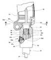
まず最初に、スクリュウドライバ10全体の構成を、図1を用いて簡単に説明する。スクリュウドライバ10の外郭を形成するハウジング12の内部には図示しない電動モータ、ギア、クラッチ等が内蔵されている。スクリュウドライバ10の先端(図1において左側)に装着されているドライバビット16は、ギアやクラッチを介して電動モータと連結されている。このため、電動モータが駆動されると、ドライバビット16は回転する。ハウジング12には、使用者が握って操作するためのハンドル12aが形成されている。ハンドル12aを握った状態で指先が操作し易い位置にトリガースイッチ14が設けられている。トリガースイッチ14は、指先で押し込むとオンになり、指先を放すと元の位置に戻りオフとなる。このトリガースイッチ14のオン/オフにより、外部から供給されている電力の電動モータへの通電と遮断が切り替えられ、これによってドライバビット16の回転と停止が制御される(電動モータに外部から電力を供給する電源コード等については、後述にて詳細に説明する)。
【0011】
続いて、本発明に係る固定式電源コード22、ソケット32、着脱式電源コード61、ハウジング12等について説明する。
本スクリュウドライバ10のハウジング12は、固定式電源コード22またはソケット32を固定できるように構成されている。ソケット32には、着脱式電源コード61が装着される。なお、図1は、ハウジング12に固定式電源コード22が固定された状態を図示している。
まず、固定式電源コード22について説明する。図1に示されているように、固定式電源コード22には、急な折れ曲がりを防止するためのコードガード24が取り付けられている。コードガード24には、横断面が円形状の嵌合部24aが形成されている。また、ハウジング12は分割面12cによって2つのハウジング(12d、12e)に分割されている。これらのハウジング(12d、12e)それぞれが組み合わされて横断面が方形状のコードガード固定部12bが形成されている。また、図1に示されているように、コードガード固定部12bには上固定面12fと下固定面12gが形成されている。このように構成されているので、固定式電源コード22は、コードガード24の嵌合部24aがコードガード固定部12bに嵌合されることにより、軸方向の動きが規制された状態でハウジング12に固定される。ハウジング12からの固定式電源コード22の取り外しは、ハウジング12eを分離することによって嵌合を解除し、後述するコードクランプによる電源コードの固定を解除することで行うことができる。
【0012】
固定式電源コード22のハウジング12と反対側の端末には、図示しない電源側プラグが設けられており、この電源側プラグが外部電源のコンセントに接続されることにより、電動工具10に電力が供給される。また、図1に示されているように、コードガード24の近傍には、スクリュウ26によってハウジング12に取り付けられるコードクランプ27が設けられている。そして、ハウジング内の固定式電源コード22は、ハウジング12とコードクランプ27との間に挟み込まれるようにして固定されている。
【0013】
次に、ソケット32の構成について説明する。図2に示されているように、ソケット32は、ホルダ33とスリーブ34から構成されている。ホルダ33は、図3、図4に良く示されているように、その上部(図4の上方を上とする)に横断面が方形状のソケット嵌合部33aが形成されている。図2に示されているように、ホルダ33には、軸方向に形成された横断面が円形の上部円形穴33dと、この上部円形穴33dよりも僅かに径が大きい下部円形穴33eが形成されている。
ホルダ33の下部円形穴33eの内周壁面には、図4に示されているように、内径方向に突出するとともに対向する位置に配置されている2つのソケット側係合片33bが形成されている。また、ホルダ33の下部外周の一部には、凹状のロック溝33cが形成されている。ロック溝33cの両側には、ホルダ33の外周面から盛り上がったストッパ33fが形成されている。
【0014】
スリーブ34は、図5、図6に示されているように、略円柱状の外形形状を有しており、上部(図5の上方を上とする)に鍔状の鍔部34aが形成されている。スリーブ34の底面から上方に向かって、スリーブ34の高さの約半分の深さの差し込み穴34bが形成されている。図6に良く示されているように、差し込み穴34bの平面形は、部分的な円弧と直線を組み合わせた形状であり、2つ形成されている直線状の内壁面の片方に凹部34cが形成されている。
差し込み穴34bには、その内側に突出するように、2本のピン35が固定されている。ピン35は、スリーブ34の上部に装着される2本の内部配線36と電気的に接続されている。スリーブ34は、図2に良く示されているように、ホルダ33の上部円形穴33dと下部円形穴33eに上方から差し込まれて、軸廻りに回動可能な状態で装着される。
【0015】
以上説明したソケット32は、ホルダ33のソケット嵌合部33aをハウジング12のコードガード固定部12bに嵌合させることにより、ハウジング12に固定することができる。このように構成されているので、ハウジング12のコードガード固定部12bには、固定式電源コード22のコードガード24の嵌合部24aを嵌合させることもできるし、ソケット32のソケット嵌合部33aを嵌合させることもできる。
【0016】
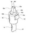
着脱式電源コード61の構成について説明する。図2に示されているように、着脱式電源コード61の一端にプラグ62が装着されている。プラグ62の下半分は、図7に示されているように、略円柱状に形成されており、その上に下半分よりも径が小さい円柱部62cと、さらにその上方に延びる差し込み部62aが形成されている(図7の上方を上とする)。差し込み部62aの片側には凸部62dが形成されている。差し込み部62aは、スリーブ34の差し込み穴34bに対応した形状に形成されている。
差し込み部62aの上面には、2つのターミナル穴66が設けられており、ターミナル穴66内の筒状端子66aは、プラグ62の下部に装着されているコード67と電気的に接続されている。円柱部62cには、外径方向に突出するとともに軸対称位置に配置されている2つのプラグ側係合片62bが形成されている。コード67のプラグ62とは反対側の端末には、固定式電源コード22と同様に電源側プラグ(図示省略)が設けられている。
【0017】
図2に示されているように、プラグ62には固定部68が設けられ、この固定部68にロック部材64が固定されている。ロック部材64は樹脂製の弾性体であり、その上部にロック片64aが形成されている。使用者が操作して矢印64bの方向にロック部材64を押すと、ロック部材64は、図2において点線で示されている64cの位置まで変形し、ロック片64aは斜め下方に移動する。ロック片64aを押していた力を解除すると、ロック部材64は弾性力によって元の位置に戻る(以下においては、力が加えられていないロック部材64の位置(図2で実線で示されている位置)を「ロック位置」、押されてロック部材64が変形している位置(図2で64cとして図示されている位置)を「アンロック位置」と言う)。
【0018】
ソケット32に着脱式電源コード61のプラグ62を接続する操作について説明する。
ソケット32にプラグ62を装着する際には、まず、ホルダ33の2つのソケット側係合片33bとの間にプラグ62の2枚のプラグ側係合片62bを通すようにしてプラグ62をソケット32の軸方向に移動させる。プラグ62をソケット32の軸方向に移動させると、プラグ62の差し込み部62aがスリーブ34の差し込み穴34bに差し込まれ、ピン35がターミナル穴66の筒状端子66aに挿入される。なお、差し込み部62aを差し込み穴34bに差し込むためには、スリーブ34の凹部34cと差し込み部62aの凸部62dとが組み合わされるようにプラグ62を位置させる必要がある。このため、プラグ62を差し込む際には、スリーブ34に対するプラグ62の軸廻り位置は一義的に定まる(この位置を、以下、差し込み可能位置と言う)。
また、ソケット32にプラグ62を差し込む際には、ロック部材64を押してアンロック位置とし、ロック片64aがホルダ33の底面と干渉するのを避ける必要がある。この操作は、プラグ62を握っている指を用いて容易に行うことができる。
【0019】
ソケット32にプラグ62が完全に差し込まれた状態で、プラグ62を差し込み可能位置から約90度回動させると、ホルダ33のソケット側係合片33bの裏側にプラグ62のプラグ側係合片62bが配置されることにより、ソケット側係合片33bとプラグ側係合片62bは係合される。ソケット側係合片33bとプラグ側係合片62bが係合されると、ソケット32とプラグ62は軸方向の動きが規制される。また、この状態ではホルダ33のロック溝33cとロック部材64のロック片64aの周方向位置が一致するので、ロック部材64を押していた力を解除すると、ロック部材64は弾性力でロック位置に戻り、ロック片64aはロック溝33cにはまり込む。ロック片64aがロック溝33cにはまり込むと、プラグ62の軸廻りの回動が規制される。ロック溝33cの両側に形成されているストッパ33fは、ロック片64aがロック溝33cから抜け出してしまうのを防止する機能を有している。
【0020】
このようにプラグ62は、ソケット側係合片33bとプラグ側係合片62bが係合されるとともにロック片64aがロック溝33cにはまり込むことにより、軸方向と回動方向の両方向の動きが規制され、ソケット32に確実に装着される。
【0021】
ソケット32からプラグ62を取り外す場合には、ロック部材64を押すことによりロック溝33cからロック片64aを抜き出してからプラグ62を軸廻りに差し込み可能位置まで回動させ、ソケット側係合片33bとプラグ側係合片62bの係合を解除する。そして、プラグ62を軸方向に引き抜けば、ソケット32からプラグ62を取り外すことができる。
【0022】
上述したソケット32へのプラグ62の装着と取り外し(着脱)は、片手の指先だけを用いて、プラグ62の軸方向移動と、回動と、ロック部材64の操作とを一連の動作として行うことができる(いわゆるワンタッチで行うことができる)。従って、このような構成のソケット32とプラグ62を用いると、着脱式電源コード61の着脱を容易に行うことができる。
【0023】
以上、本発明の具体例を詳細に説明したが、これらは例示にすぎず、特許請求の範囲を限定するものではない。特許請求の範囲に記載の技術には、以上に例示した具体例を様々に変形、変更したものが含まれる。
また、本明細書または図面に説明した技術要素は、単独であるいは各種の組み合わせによって技術的有用性を発揮するものであり、出願時の請求項記載の組み合わせに限定されるものではない。また、本明細書または図面に例示した技術は複数目的を同時に達成するものであり、そのうちの一つの目的を達成すること自体で技術的有用性を持つものである。
従って、例えば、以下に記載するように構成することもできる。
【0024】
(1)ハウジングに対するソケットあるいは固定式電源コードの固定は、嵌合に限られるものではない。例えば、スクリュウ結合、圧入等によって固定が行われてもよい。
【図面の簡単な説明】
【図1】本発明の実施に形態に係るスクリュウドライバの側面図(固定式電源コードがハウジングに固定された状態)
【図2】本発明の実施の形態に係るハウジングとソケットとプラグの装着状態の縦断面図
【図3】図2のIII−III線断面図
【図4】本発明の実施の形態に係るソケットの斜視図
【図5】本発明の実施の形態に係るスリーブの縦断面図
【図6】図5のVI―VI線矢視図
【図7】本発明の実施の形態に係るプラグの斜視図
【符号の説明】
10:スクリュウドライバ
12:ハウジング、12a:ハンドル、12b:コードガード固定部、12c:分割面、12d:ハウジング、12e:ハウジング、12f:上固定面、12g:下固定面
14:トリガースイッチ
16:ドライバビット
22:固定式電源コード
24:コードガード、24a:嵌合部
26:スクリュウ
27:コードクランプ」
32:ソケット
33:ホルダ、33a:ソケット嵌合部、33b:ソケット側係合片、33c:ロック溝、33d:上部円形穴、33e:下部円形穴、33f:ストッパ
34:スリーブ、34a:鍔部、34b:差し込み穴、34c:凹部
35:ピン
36:内部配線
61:着脱式電源コード
62:プラグ、62a:差し込み部、62b:プラグ側係合片、62c:円柱部、62d:凸部
64:ロック部材、64a:ロック片、64b:押し方向を示す矢印、64c:アンロック位置
66:ターミナル穴、66a:筒状端子
67:コード部
68:固定部[0001]
BACKGROUND OF THE INVENTION
The present invention relates to a power tool. In particular, the present invention relates to a technique for fixing a power cord for supplying power to a power tool to a housing.
[0002]
[Prior art]
The power tool is driven by electric power supplied from the outside by a power cord. If the power cord is used for a long time and is repeatedly bent, it may break. In addition, a long power cord is necessary when the power tool is used in a state where the power source is at a distance from the power source. However, when the power tool is used in a state where the distance from the power source is close, the long power cord is an obstacle. Therefore, exchange power cord disconnected, to be able to replace the power cord length different technique for detachable power cord is known (e.g., JP-2001 -179 660 JP ). This technique has a socket fixed to the housing of the electric power tool and a detachable power cord provided with a plug. And by attaching or detaching the plug to or from the socket, the detachable power cord can be replaced or replaced.
On the other hand, an electric tool in which a power cord is directly fixed to a housing is also used. Such a power tool cannot be easily replaced with a power cord, but has a simple structure.
[0003]
[Problems to be solved by the invention]
However, the conventional housing of the electric power tool has been used exclusively for the shape of the socket or the power cord to be fixed. That is, since separate (two types) housings for sockets and power cords were prepared, the user could not exchange for sockets and power cords according to the purpose.
[0004]
The present invention has been made to solve such a problem, and an object of the present invention is to provide a technique that allows a user to replace a fixed type and a detachable type according to the purpose.
[0005]
[Means for solving the problem, operation and effect]
The electric power tool according to claim 1 is supplied with electric power from the outside by a power cord. Then, the housing of the power tool is encoded guard fixing portion forming, its code guard fixing part isa cord guard of fixed power cordand detachable detachable socket power cord andcan be mountedinterchangeably Yes.
The electric power tool described above can be attached to the cord guard fixing portion with the cord guard of the fixed power cord, or can be attached to the socket. Therefore, the user can perform work by exchanging the fixed power cord and the socket according to the purpose.
[0006]
The electric power tool according to claim 1, wherein the cord guard fixing portion has a through hole formed in the housing and a fitting portion formed in the middle of the through hole, and the cord guard and socket of the fixed power cord Preferably, each has a retaining portion that fits into the fitting portion.
If comprised in this way, a fixed type power cord or a socket can be attached to a cord fixing part by fitting.
[0007]
The power supply connection device according to claim 3can be attached to a cord guard fixing portion formed in a housing of an electric tool to which electric power is supplied from the outside by afixed power cord so that the cord guard of the fixed power cord can be replaced.comprising a socketsuch,the detachable power cord is removably on the socket. The socket has a socket-side electrical terminal and a socket-side engagement portion, and the plug provided at one end of the detachable power cord has a plug-side electrical terminal and a plug-side engagement portion. When the plug is disposed at the first position around the axis with respect to the socket, the engagement between the socket side engaging portion and the plug side engaging portion is released, and the plug side electric terminal can be inserted into and removed from the socket side electric terminal. When the plug side electrical terminal is inserted into the socket side electrical terminal and the plug is rotated around the axis with respect to the socket and disposed at the second position, the socket side engagement portion and the plug side engagement are The parts engage and the plug cannot be inserted or removed from the socket.
Since the engagement is thus performed and the plug cannot be inserted into and removed from the socket, the plug is prevented from being inadvertently detached from the socket during operation of the power tool.
[0008]
The power connection device according to claim 3, further comprising a lock mechanism that fixes the position of the plug with respect to the socket at the second position when the plug is disposed at the second position with respect to the socket ( Claim 4).
By providing the lock mechanism for fixing the plug in the second position, the plug is prevented from being inadvertently detached from the socket.
[0010]
DETAILED DESCRIPTION OF THE INVENTION
An embodiment in which the present invention is applied to a
First, the overall configuration of the
[0011]
Next, the
The
First, the
[0012]
A terminal on the opposite side of the
[0013]
Next, the configuration of the
On the inner peripheral wall surface of the lower circular hole 33e of the
[0014]
As shown in FIGS. 5 and 6, the
Two
[0015]
The
[0016]
The configuration of the
Two
[0017]
As shown in FIG. 2, the
[0018]
An operation of connecting the
When the
Further, when the
[0019]
When the
[0020]
As described above, the
[0021]
When the
[0022]
The above-described attachment and detachment (detachment) of the
[0023]
Specific examples of the present invention have been described in detail above, but these are merely examples and do not limit the scope of the claims. The technology described in the claims includes various modifications and changes of the specific examples illustrated above.
Further, the technical elements described in the present specification or the drawings exhibit technical usefulness alone or in various combinations, and are not limited to the combinations described in the claims at the time of filing. In addition, the technology illustrated in the present specification or the drawings achieves a plurality of objects at the same time, and has technical utility by achieving one of the objects.
Therefore, for example, it can also be configured as described below.
[0024]
(1) Fixing the socket or the fixed power cord to the housing is not limited to fitting. For example, fixing may be performed by screw connection, press fitting, or the like.
[Brief description of the drawings]
FIG. 1 is a side view of a screw driver according to an embodiment of the present invention (a state where a fixed power cord is fixed to a housing).
2 is a longitudinal sectional view of a housing, a socket and a plug according to an embodiment of the present invention. FIG. 3 is a sectional view taken along line III-III in FIG. 2. FIG. 4 is a socket according to an embodiment of the present invention. FIG. 5 is a longitudinal sectional view of the sleeve according to the embodiment of the present invention. FIG. 6 is a view taken along line VI-VI in FIG. 5. FIG. 7 is a perspective view of the plug according to the embodiment of the present invention. [Explanation of symbols]
10: Screw driver 12: Housing, 12a: Handle, 12b: Cord guard fixing part, 12c: Dividing surface, 12d: Housing, 12e: Housing, 12f: Upper fixing surface, 12g: Lower fixing surface 14: Trigger switch 16: Driver Bit 22: Fixed power cord 24: Cord guard, 24a: Mating portion 26: Screw 27: Cord clamp "
32: Socket 33: Holder, 33a: Socket fitting portion, 33b: Socket side engagement piece, 33c: Lock groove, 33d: Upper circular hole, 33e: Lower circular hole, 33f: Stopper 34: Sleeve, 34a:
Claims (4)
Translated fromJapanesePriority Applications (4)
| Application Number | Priority Date | Filing Date | Title |
|---|---|---|---|
| JP2001319277AJP3830799B2 (en) | 2001-10-17 | 2001-10-17 | Power tools and power connection devices for power tools |
| US10/270,358US20030070822A1 (en) | 2001-10-17 | 2002-10-15 | Power tools attachable to removable or fixed power cords |
| EP02023212AEP1304769B1 (en) | 2001-10-17 | 2002-10-16 | Power tools attachable to removable or fixed power cords |
| DE60230225TDE60230225D1 (en) | 2001-10-17 | 2002-10-16 | Power tools connected to fixed or removable power lines |
Applications Claiming Priority (1)
| Application Number | Priority Date | Filing Date | Title |
|---|---|---|---|
| JP2001319277AJP3830799B2 (en) | 2001-10-17 | 2001-10-17 | Power tools and power connection devices for power tools |
Publications (3)
| Publication Number | Publication Date |
|---|---|
| JP2003117855A JP2003117855A (en) | 2003-04-23 |
| JP2003117855A5 JP2003117855A5 (en) | 2005-04-07 |
| JP3830799B2true JP3830799B2 (en) | 2006-10-11 |
Family
ID=19136852
Family Applications (1)
| Application Number | Title | Priority Date | Filing Date |
|---|---|---|---|
| JP2001319277AExpired - Fee RelatedJP3830799B2 (en) | 2001-10-17 | 2001-10-17 | Power tools and power connection devices for power tools |
Country Status (4)
| Country | Link |
|---|---|
| US (1) | US20030070822A1 (en) |
| EP (1) | EP1304769B1 (en) |
| JP (1) | JP3830799B2 (en) |
| DE (1) | DE60230225D1 (en) |
Families Citing this family (17)
| Publication number | Priority date | Publication date | Assignee | Title |
|---|---|---|---|---|
| USD513951S1 (en)* | 2004-10-26 | 2006-01-31 | One World Technologies Limited | Screw gun |
| US7175456B2 (en)* | 2005-02-28 | 2007-02-13 | Robert Bosch Gmbh | Anti-disengagement connect system for a power tool |
| SE530669C2 (en)* | 2006-03-20 | 2008-08-05 | Atlas Copco Tools Ab | Electric power tool with swivel cable connection |
| USD592927S1 (en)* | 2006-09-12 | 2009-05-26 | Black & Decker Inc. | Drill |
| USD592477S1 (en)* | 2006-09-12 | 2009-05-19 | Black & Decker Inc. | Drill |
| USD593830S1 (en)* | 2007-08-23 | 2009-06-09 | Black & Decker Inc. | Driver |
| USD595553S1 (en)* | 2007-08-23 | 2009-07-07 | Black & Decker Inc. | Driver |
| USD593829S1 (en)* | 2007-08-23 | 2009-06-09 | Black & Decker Inc. | Driver |
| USD589316S1 (en)* | 2007-08-23 | 2009-03-31 | Black & Decker Inc. | Driver |
| AU2011220340A1 (en) | 2010-02-25 | 2012-10-11 | Demain Technology Pty Ltd | A power tool storage and package system |
| JP2012049074A (en) | 2010-08-30 | 2012-03-08 | Makita Corp | Battery pack of electric tool |
| DE102011080815A1 (en)* | 2011-08-11 | 2013-02-14 | Hilti Aktiengesellschaft | Hand tool |
| CN103654603B (en)* | 2012-09-26 | 2017-04-19 | 科沃斯机器人股份有限公司 | Robot for cleaning windows |
| KR101679651B1 (en) | 2014-11-11 | 2016-11-25 | 황명구 | Connector for electronic equipment |
| JP6652833B2 (en)* | 2015-06-03 | 2020-02-26 | 京セラインダストリアルツールズ株式会社 | Power tool connector device |
| US11395996B2 (en)* | 2018-08-10 | 2022-07-26 | Hamilton Beach Brands, Inc. | Immersion mixer with trigger manipulable from multiple grasping locations |
| DE102023211315A1 (en)* | 2023-11-14 | 2025-05-15 | Robert Bosch Gesellschaft mit beschränkter Haftung | System consisting of an electric motor-driven hand tool and at least one power supply cable connectable to the hand tool |
Family Cites Families (12)
| Publication number | Priority date | Publication date | Assignee | Title |
|---|---|---|---|---|
| US3770331A (en)* | 1971-09-02 | 1973-11-06 | Rockwell International Corp | Combination bearing seat for motors |
| US3843224A (en)* | 1972-12-21 | 1974-10-22 | Black & Decker Mfg Co | Detachable cord set for electric device |
| AU6231673A (en)* | 1973-03-30 | 1975-05-15 | Black & Decker Mfg Co | Extension cord adaptor |
| US3938873A (en)* | 1974-10-03 | 1976-02-17 | Kimball James F | Electrical plug mounting device for power tools |
| US4175247A (en)* | 1978-06-26 | 1979-11-20 | Cooper Industries, Inc. | Electric motor control for conductor wrapping tool |
| IT8120969U1 (en)* | 1981-03-04 | 1982-09-04 | Star Utensili Elett S P A | Improved switch for power tools |
| US4500154A (en)* | 1983-03-30 | 1985-02-19 | Allied Corporation | Electrical connector assembly having an anti-decoupling device |
| US4641899A (en)* | 1985-07-18 | 1987-02-10 | Allied Corp. | Multi-part electrical connector assembly |
| US5354215A (en)* | 1993-06-24 | 1994-10-11 | Viracola Joseph R | Circuit interconnect for a power tool |
| US6368133B1 (en)* | 1999-11-19 | 2002-04-09 | Milwaukee Electric Tool Corporation | Quick lock power cord |
| US6443762B1 (en)* | 2001-06-04 | 2002-09-03 | Black & Decker Inc. | Power tool cord retainer |
| US6443753B1 (en)* | 2001-06-04 | 2002-09-03 | Black & Decker Inc. | Power tool cord retainer |
- 2001
- 2001-10-17JPJP2001319277Apatent/JP3830799B2/ennot_activeExpired - Fee Related
- 2002
- 2002-10-15USUS10/270,358patent/US20030070822A1/ennot_activeAbandoned
- 2002-10-16EPEP02023212Apatent/EP1304769B1/ennot_activeExpired - Lifetime
- 2002-10-16DEDE60230225Tpatent/DE60230225D1/ennot_activeExpired - Lifetime
Also Published As
| Publication number | Publication date |
|---|---|
| EP1304769B1 (en) | 2008-12-10 |
| US20030070822A1 (en) | 2003-04-17 |
| DE60230225D1 (en) | 2009-01-22 |
| JP2003117855A (en) | 2003-04-23 |
| EP1304769A2 (en) | 2003-04-23 |
| EP1304769A3 (en) | 2004-01-07 |
Similar Documents
| Publication | Publication Date | Title |
|---|---|---|
| JP3830799B2 (en) | Power tools and power connection devices for power tools | |
| TWI716667B (en) | Mounting member of battery unit for bicycle, and battery unit assembly including the mounting member | |
| CN102161193B (en) | There is the electric tool disconnecting Lock Part | |
| JP3166805U (en) | Positioning structure of battery pack for electric vehicle | |
| JP4767923B2 (en) | Electrical connector and connector assembly | |
| KR20040068965A (en) | Side handles on drill/drivers | |
| JP5690914B1 (en) | Power supply connector | |
| JP7118343B2 (en) | socket | |
| AU2016101315A4 (en) | Power tool | |
| JP2017087413A (en) | Shaft center retainer of high speed rotary wrench and high speed rotary wrench with application of the same | |
| JP2009056580A (en) | Spanner | |
| CN111590524B (en) | Head and body quick-change structure of multifunctional power tool and multifunctional power tool | |
| TWM290341U (en) | Vehicle charging seat of battery for motor-driven tool | |
| EP3427900B1 (en) | Power tool including power tool base couplable with power tool implements | |
| JP3745630B2 (en) | Rotary connector | |
| WO2023077761A1 (en) | Power tool capable of realizing fast assembly and assembly locking | |
| CN212170302U (en) | Quick-release quick-assembly connecting structure and handheld tool | |
| KR102342861B1 (en) | Auxiliary handle used for power tool | |
| JP3544204B1 (en) | Female plug of optical connector | |
| JP2016225272A (en) | Connector device for electric power tool | |
| CN215238012U (en) | Charging type electric drill | |
| CN108068066B (en) | Conversion chuck, tool main body matched with conversion chuck for use and matched use method | |
| TWI650208B (en) | Switching mechanism of ratchet assembly | |
| CN218397964U (en) | Combined hand tool | |
| CN111360767B (en) | Main unit and tool rest dismounting structure and hand tool |
Legal Events
| Date | Code | Title | Description |
|---|---|---|---|
| A521 | Request for written amendment filed | Free format text:JAPANESE INTERMEDIATE CODE: A523 Effective date:20040428 | |
| A621 | Written request for application examination | Free format text:JAPANESE INTERMEDIATE CODE: A621 Effective date:20040428 | |
| RD02 | Notification of acceptance of power of attorney | Free format text:JAPANESE INTERMEDIATE CODE: A7422 Effective date:20040428 | |
| A977 | Report on retrieval | Free format text:JAPANESE INTERMEDIATE CODE: A971007 Effective date:20050415 | |
| A131 | Notification of reasons for refusal | Free format text:JAPANESE INTERMEDIATE CODE: A131 Effective date:20051108 | |
| A521 | Request for written amendment filed | Free format text:JAPANESE INTERMEDIATE CODE: A523 Effective date:20051222 | |
| TRDD | Decision of grant or rejection written | ||
| A01 | Written decision to grant a patent or to grant a registration (utility model) | Free format text:JAPANESE INTERMEDIATE CODE: A01 Effective date:20060711 | |
| A61 | First payment of annual fees (during grant procedure) | Free format text:JAPANESE INTERMEDIATE CODE: A61 Effective date:20060712 | |
| R150 | Certificate of patent or registration of utility model | Free format text:JAPANESE INTERMEDIATE CODE: R150 | |
| FPAY | Renewal fee payment (event date is renewal date of database) | Free format text:PAYMENT UNTIL: 20090721 Year of fee payment:3 | |
| FPAY | Renewal fee payment (event date is renewal date of database) | Free format text:PAYMENT UNTIL: 20090721 Year of fee payment:3 | |
| FPAY | Renewal fee payment (event date is renewal date of database) | Free format text:PAYMENT UNTIL: 20100721 Year of fee payment:4 | |
| FPAY | Renewal fee payment (event date is renewal date of database) | Free format text:PAYMENT UNTIL: 20100721 Year of fee payment:4 | |
| FPAY | Renewal fee payment (event date is renewal date of database) | Free format text:PAYMENT UNTIL: 20110721 Year of fee payment:5 | |
| FPAY | Renewal fee payment (event date is renewal date of database) | Free format text:PAYMENT UNTIL: 20110721 Year of fee payment:5 | |
| FPAY | Renewal fee payment (event date is renewal date of database) | Free format text:PAYMENT UNTIL: 20120721 Year of fee payment:6 | |
| FPAY | Renewal fee payment (event date is renewal date of database) | Free format text:PAYMENT UNTIL: 20120721 Year of fee payment:6 | |
| FPAY | Renewal fee payment (event date is renewal date of database) | Free format text:PAYMENT UNTIL: 20120721 Year of fee payment:6 | |
| FPAY | Renewal fee payment (event date is renewal date of database) | Free format text:PAYMENT UNTIL: 20130721 Year of fee payment:7 | |
| R250 | Receipt of annual fees | Free format text:JAPANESE INTERMEDIATE CODE: R250 | |
| R250 | Receipt of annual fees | Free format text:JAPANESE INTERMEDIATE CODE: R250 | |
| LAPS | Cancellation because of no payment of annual fees |