JP3828474B2 - Position detection input / output device - Google Patents
Position detection input / output deviceDownload PDFInfo
- Publication number
- JP3828474B2 JP3828474B2JP2002293812AJP2002293812AJP3828474B2JP 3828474 B2JP3828474 B2JP 3828474B2JP 2002293812 AJP2002293812 AJP 2002293812AJP 2002293812 AJP2002293812 AJP 2002293812AJP 3828474 B2JP3828474 B2JP 3828474B2
- Authority
- JP
- Japan
- Prior art keywords
- computer
- input
- living body
- output
- user
- Prior art date
- Legal status (The legal status is an assumption and is not a legal conclusion. Google has not performed a legal analysis and makes no representation as to the accuracy of the status listed.)
- Expired - Fee Related
Links
Images


Landscapes
- Position Input By Displaying (AREA)
- User Interface Of Digital Computer (AREA)
Description
Translated fromJapanese【0001】
【発明の属する技術分野】
本発明は、例えば、ウェアラブルコンピュータのデータ通信のために使用されるトランシーバを用いた位置検出入出力装置に関し、特に、送信すべき情報に基づく電界を電界伝達媒体に誘起させるとともに、電界伝達媒体に誘起された電界を検出して情報の送受信を行うトランシーバを用いた位置検出入出力装置に関する。
【0002】
【従来の技術】
携帯端末の小型化および高性能化によりウェアラブルコンピュータが注目されているが、図8はこのようなウェアラブルコンピュータを人間に装着して使用する場合の例を示している。同図に示すように、ウェアラブルコンピュータ1はそれぞれトランシーバ3を介して人間の腕、肩、胴体などに装着されて互いにデータの送受信を行うとともに、更に手足の先端で触れられるよう壁や床に設けられたトランシーバ3a、3bとケーブルとを介して外部に設けられたパソコン(PC)5と通信を行っている。
【0003】
ここで、このようなウェアラブルコンピュータ1間、およびウェアラブルコンピュータ1とPC5間とのデータ通信に使用されるトランシーバ3は、レーザ光と電気光学結晶を用いた電気光学的手法による信号検出技術を利用していて、送信すべき情報に基づく電界を電界伝達媒体である生体に誘起させ、この誘起した電界を用いて情報の送受信を行うものである。
【0004】
ところで、昨今、ユビキタスコンピューティングという言葉を耳にするが、このようなユビキタスコンピューティング環境を実現するインターフェースの1つとして、例えば、「Pick-and-Drop」という、複数コンピュータ環境での直接操作技法が存在する。Pick-and-Dropのシステムにおいては、特殊ペンによりある画面(コンピュータ)内のオブジェクトをピックし、他の画面(コンピュータ)においてドロップすると、オブジェクトはある画面から他の画面に移動することができるので、容易に複数コンピュータ間での情報の移動が実現できるようになっている。
【0005】
尚、この出願に関連する先行技術文献情報としては、次のものがある。
【0006】
【特許文献1】
特開2001−352298公報
【0007】
【非特許文献1】
Jun Rekimoto, "Pick-and-Drop: A Direct Manipulation Technique for Multiple Computer Environments",[平成14年9月10日検索]、インターネット<URL: http://www.csl.sony.co.jp/person/rekimoto/papers/wiss97.pdf>
【0008】
【発明が解決しようとする課題】
しかし、上述したPick-and-Dropのシステムは、実際には、どの特殊ペンがどのオブジェクトを保存しているかを管理するサーバとコンピュータ間の相互通信により、オブジェクトを移動させるネットワーク型のシステムであるため、サーバとコンピュータ間が有線および無線で接続されるネットワーク環境を予め構築しておかなければならないという問題がある。
【0009】
本発明は、上記の事情を鑑みてなされたものであり、送信すべき情報に基づく電界を電界伝達媒体に誘起させるとともに、電界伝達媒体に誘起された電界を検出して情報の送受信を行うトランシーバを用いることにより、ネットワーク環境を予め構築しなくても、Pick-and-Dropシステムのデータ通信を的確に行い得る位置検出入出力装置を提供することを目的とする。
【0010】
【課題を解決するための手段】
上記目的を達成するため、請求項1記載の本発明は、送信すべき情報に基づく電界を電界伝達媒体である生体に誘起させるとともにこの誘起した電界を検出して情報の送受信を行う複数のトランシーバを利用して、複数のコンピュータ間のオブジェクト移動を行うコンピュータシステムにおける位置検出入出力装置であって、利用者は、第1のコンピュータと、当該第1のコンピュータに接続された第1のトランシーバとを装着し、前記位置検出入出力装置は、入出力手段と、当該入出力手段および第2のコンピュータに接続された第2のトランシーバと、を有し、前記入出力手段は、前記利用者の生体が触れることにより、当該利用者の生体が触れた位置に関する位置情報を検出し、当該位置情報を前記第2のコンピュータに出力し、前記第2のトランシーバは、前記入出力手段および前記利用者の生体を介して前記第1のトランシーバとの通信経路を確立するとともに、前記第2のコンピュータが前記位置情報に基づいて特定したオブジェクトを、前記通信経路を介して前記第1のトランシーバに送信し、前記入出力手段は、前記利用者の生体が触れる導電性膜と、前記導電性膜に隣接し、前記導電性膜に誘起した電界の漏洩を防ぐ絶縁性膜と、前記絶縁性膜に隣接し、前記利用者の生体が前記導電性膜に触れた場合には前記導電性膜および前記絶縁性膜が押下されることにより、前記利用者の生体が触れた位置に関する位置情報を検出して、前記第2のコンピュータに出力する位置検出手段と、を有することを要旨とする。
【0011】
請求項1記載の本発明にあっては、第1のコンピュータおよび第1のトランシーバを装着した利用者の生体が入出力手段に触れると、電界伝達媒体である生体を介して第1および第2のトランシーバが通信可能となるので、第1のコンピュータと、第2のコンピュータ間でオブジェクト情報の送受信が可能となる。一方、入出力手段は、利用者の生体が触れた位置に関する情報を検出し、該情報を第2のコンピュータに出力するので、第2のコンピュータは、この位置情報からオブジェクトを特定する。そして、第2のトランシーバは、第2のコンピュータが特定したオブジェクトを第1のトランシーバに送信する。これにより、予めコンピュータ間を結ぶネットワーク環境を構築しなくても、利用者が入出力手段に触れるだけで、電界伝達媒体を介した通信経路が確立し、複数コンピュータ間のオブジェクト移動を簡単に実現することができる。また、ピアーツーピアー (peer to peer)の通信を行うコンピュータシステムであるので、ネットワーク型のコンピュータシステムに比べて、セキュリティを高めることができる。
また、利用者の生体が導電性膜に触れても、絶縁性膜が導電性膜に誘起した電界の漏洩を防ぐので、電界伝達媒体である生体を介して第1および第2のトランシーバが通信可能となり、第1のコンピュータと、第2のコンピュータ間でオブジェクトの送受信が可能となる。
また、生体の押下に基づいて押下位置を検出する位置検出入出力装置であっても、絶縁性膜が電界の外部への漏洩あるいは外部からの電界の影響を防ぐので、電界伝達媒体を介して的確に複数コンピュータ間においてオブジェクトを移動させることができる。
【0012】
請求項2記載の本発明は、請求項1記載の発明において、前記第2のトランシーバは、前記第2のコンピュータが前記位置情報にもとづいて前記利用者の生体が触れた位置にオブジェクトが表示されていないと判断した場合、前記第1のコンピュータに記憶されたオブジェクトを前記通信経路を介して受信し、前記第2のコンピュータに出力することを要旨とする。
【0014】
請求項3記載の本発明は、請求項1または請求項2記載の発明において、前記導電性膜、および前記絶縁性膜は透明であり、前記位置検出手段は、前記第2のコンピュータからオブジェクトの出力を受け、該オブジェクトを表示することを要旨とする。
【0015】
請求項3記載の本発明にあっては、導電性膜、および絶縁性膜は透明であり、位置検出手段は、第2のコンピュータからオブジェクトを表示する。これにより、利用者はオブジェクトを見ることができる。
【0016】
請求項4記載の本発明は、請求項1または請求項2記載の発明において、前記導電性膜は、前記第2のコンピュータからのオブジェクトの出力を投影装置を介した投影像として表示することを要旨とする。
以上
【0017】
請求項4記載の本発明にあっては、投影装置は、第2のコンピュータからのオブジェクト出力を導電性膜に投影像として表示する。これにより、導電性膜、および絶縁性膜の色を問わず、利用者はオブジェクトを見ることができる。
【0018】
【発明の実施の形態】
以下、本発明の実施の形態を図面を用いて説明する。
【0019】
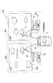
本発明の実施の形態に係る位置検出入出力装置を説明する前に、図7を用いて、Pick-and-Dropによるオブジェクト入出力システム100の概念を説明する。
【0020】
図7において、携帯情報端末1bおよびトランシーバ3bを身につけた利用者の生体がコンピュータ(画面)20aのあるオブジェクト4(例えば、魚)に触れて離すと(Pick)、このオブジェクト4はオブジェクトを管理しているオブジェクト管理部7aからトランシーバ3a、生体、トランシーバ3bを介して自己の携帯情報端末1bに移動し、画面20a上に表示されていたオブジェクトは消失する。次に、利用者の生体が他のコンピュータ(画面)20cに触れると(Drop)、自己の携帯情報端末1bに移動していたオブジェクト4がトランシーバ3b、生体、3cを介してオブジェクト管理部7cに移動し、画面20c上の利用者が触れた部分にオブジェクト4が表示される。このように、オブジェクト入出力システム100は、利用者の生体によるPick-and-Dropという直接操作技法を用いることにより、あたかもオブジェクトが現実空間での物理的な移動をしているかのよう操作感を与えるシステムである。
【0021】
次に、このようなオブジェクト入出力システム100のインターフェース部分に用いられる位置検出入出力装置について説明する。 図1は、本発明の実施形態に係る位置検出入出力装置10 の構成を示す図である。位置検出入出力装置10 は、抵抗膜方式のタッチパネルを採用しており、入出力手段としての 導電性膜11、絶縁性膜12および位置検出装置13と、トランシーバ3を有する構成で、携帯情報端末1bおよびトランシーバ3bを備えた利用者が導電性膜11に触れることにより、導電性膜11、通信線14、トランシーバ3を介する第1の通信経路と、導電性膜11、絶縁性膜12、位置検出装置13、出力線15を介する第2の通信経路とが独立して成立し、第2の通信経路により取得された位置および時間に関する情報に基づいて、オブジェクトの送受信を第1の通信回路経由で行うようになっている装置である。尚、出力線15およびトランシーバ3の先はオブジェクトを管理しているコンピュータに接続されるようになっている。
【0022】
導電性膜11は導電体で形成され、利用者の生体が触れると、導電性膜11に誘起した電界をトランシーバ3に通信線14を介して出力するようになっている。
【0023】
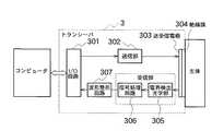
ここで、トランシーバ3は、詳しくは、図2に示すように、生体に装着された別のトランシーバから生体に誘起されて伝達されてくる電界を絶縁膜304を介して送受信電極303で検出し、この電界を電界検出光学部305に結合して電気信号に変換する。この電気信号は、信号処理回路306で増幅、雑音除去などの信号処理を施され、更に波形整形回路307で波形整形されてから、入出力(I/O)回路301を介してコンピュータに出力されるようになっている。
【0024】
また、トランシーバ3は、コンピュータからの送信データを入出力(I/O)回路301を介して受け取ると、この送信データを送信部302を介して送受信電極303に供給し、該送受信電極303および絶縁膜304を介して生体に電界を誘起させ、この電界を生体に伝達させるようになっている。
【0025】
従って、このようなトランシーバ3を位置検出入出力装置10および利用者が備え、かつ利用者が導電性膜11に触れることによって、生体を介してトランシーバ3に接続された双方の コンピュータ間通信が可能となり、オブジェクトの移動ができるようになっている。
【0026】
絶縁性膜12は導電性膜11に隣接しており、導電性膜11に誘起した電界の漏洩を防ぐものであり、これにより電界は弱まらずにトランシーバ3に的確に伝わるようになっている。
【0027】
位置検出装置13は絶縁性膜12に隣接しており、利用者が導電性膜11に触れた際には、導電性膜11および絶縁性膜12が押下され、この押下された位置が位置検出装置13に伝わるようになっているので、位置検出装置13は利用者が触れた位置、時間などの情報を検出し、該情報を出力線15を介して接続先のコンピュータに出力するようになっている。
【0028】
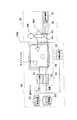
次に、このような位置検出入出力装置10を用いた、Pick-and-Dropによるオブジェクト入出力システム100を図3を用いて説明する。
【0029】
オブジェクト入出力システム100は、オブジェクト4i(i=a,b,…,n)を管理するオブジェクト入出力装置20と、人が備えるウェアラブルコンピュータ群30とを有する構成である。尚、図3には、オブジェクト入出力装置20およびウェアラブルコンピュータ群30は1つしか図示されていないが、オブジェクト入出力装置20およびウェアラブルコンピュータ群30は複数存在していてもよい。
【0030】
オブジェクト入出力装置20は、オブジェクト4iを管理するとともに、表示装置16に表示されたオブジェクト4iを利用者が触れて操作することにより、オブジェクト4iの入出力を制御して、ウェアラブルコンピュータ群30と通信を行う装置であり、オブジェクト管理装置22、オブジェクト記憶装置23、入力装置21、出力装置24、トランシーバ3a、および表示装置16を備えている。
【0031】
オブジェクト記憶装置23は、オブジェクト4iを記憶する装置であり、オブジェクト管理装置22は、利用者が触れた位置や利用者の触れる操作(クリック、ドラッグなど)により、オブジェクト記憶装置23に記憶されたオブジェクトの入出力を制御する装置である。ここで、本発明におけるオブジェクトとは、属性(色、形、材質など)や機能(動く、消えるなど)やデータ(静止画、動画、音、時刻など)を有するものをいう。
【0032】
表示装置16は、前述した位置検出入出力装置10の導電性膜11、絶縁性膜12および位置検出装置13からなる装置をいい、前述した入出力手段としての機能の他、オブジェクト4iを表示する機能を有する装置である。尚、導電性膜11、絶縁性膜12は透明な膜であるため、位置検出装置13に表示されたオブジェクト4iは利用者から見えるようになっている。
【0033】
入力装置21は、位置検出装置13から受け取った位置や時間に関する情報をオブジェクト管理装置22に出力するようになっている。また、上記情報から利用者の触れる操作(クリック、ドラッグなど)を判別し、操作に関する情報もオブジェクト管理装置22に出力するようになっている。
【0034】
出力装置24は、オブジェクト管理装置22から送られるオブジェクト4iを表示装置16に出力する装置である。
【0035】
人が身につけているウェアラブルコンピュータ群30は、人間の腕、肩、胴体などに装着されたトランシーバ3bと、トランシーバ3bに接続された端末機器1bから構成され、生体を介してオブジェクト入力装置20と通信可能となっている。
【0036】
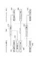
次に、オブジェクト入出力システム100の動作について、図4および5を用いて説明する。ここで、図4はオブジェクトをピックした場合の動作を説明するシーケンス図であり、図5はオブジェクトをドロップした場合の動作を説明するシーケンス図である。
【0037】
まず、利用者が表示装置16上に表示されているオブジェクト4に触れると、電界伝達媒体である生体を介して、オブジェクト入出力装置20とウェアラブルコンピュータ群30とに通信路が確立し、両コンピュータは通信が可能となる(ステップS10、S20)。
【0038】
一方、オブジェクト入出力装置20においては、利用者が触れた位置、および時間に関する情報を位置検出装置13が検出するので、該情報を入力装置21を介してオブジェクト管理装置22に出力する(ステップS30)。オブジェクト管理装置22は、オブジェクト記憶装置23に記憶されたオブジェクトに関する情報と入力装置21から取得した位置情報とから触れられたオブジェクトを特定し、また、入力装置21から取得した操作情報からオブジェクトの入出力を制御する(ステップS30)。そして、利用者の操作がpickであると判断した場合には、選択されたオブジェクトを生体を介してウェアラブルコンピュータ群30の端末機器1bに送信する(ステップS40、S50)。尚、上記のオブジェクトの移動は、利用者の生体がオブジェクト4に触れている間に行われるものであり、利用者の生体がオブジェクト4から離れると、電界伝達媒体による通信は成立しないので、オブジェクト4の移動は行われない(ステップS60、S70)。
【0039】
その後、利用者が同一のもしくは他の入出力装置20の表示装置16(オブジェクト4は表示されていない部分)に触れると、同様にして、電界伝達媒体である生体を介して、オブジェクト入出力装置20とウェアラブルコンピュータ群30とに通信路が確立し、両コンピュータは通信が可能となる(ステップS110、S120)。
【0040】
一方、オブジェクト入出力装置20においては、利用者が触れた位置、および時間に関する情報を位置検出装置13が検出するので、該情報を入力装置21を介してオブジェクト管理装置22に出力する(ステップS130)。オブジェクト管理装置22は、オブジェクト記憶装置23に記憶されたオブジェクトに関する情報と入力装置21から取得した位置情報から、触れられた位置にはオブジェクト4が存在しないと判断して、端末機器1に存するオブジェクト4を受信し、触れられた位置にオブジェクト4を表示する(ステップS140〜S160)。尚、上記のオブジェクト4の移動は、利用者の生体が画面に触れている間に行われるものであり、利用者の生体が画面から離れると、電界伝達媒体による通信は成立しないので、オブジェクト4iの移動は行われない(ステップS170、S180)。
【0041】
従って、本実施の形態の位置検出入出力装置10によれば、オブジェクト入出力システム100において、電界伝達媒体を介して通信可能なトランシーバ3を用いることにより、利用者の生体が位置検出入出力装置10に触れるという簡単な動作のみでオブジェクトを自由に移動させることができるので、ネットワーク環境を予め構築しなくても、Pick-and-Dropのシステムを実現することができる。
【0042】
また、複数の利用者が同一画面のオブジェクト4iを操作する場合においても、操作情報として時間に関する情報を有しているため、操作者の特定をすることができるので、複数の利用者の共同作業や議論の効率を高めることができる。
【0043】
さらに、コンピュータを有線および無線で接続しているネットワーク型のシステムに比べて、オブジェクト入出力システム100は、電界伝達媒体を介するピアーツーピアの通信であるため、通信のセキュリティを高めることができる。
【0044】
以上、本発明の実施の形態について説明してきたが、本発明の要旨を逸脱しない範囲において、本発明の実施の形態に対して種々の変形や変更を施すことができる。例えば、上記実施の形態の位置検出入出力装置10は、抵抗膜方式のタッチパネルを採用したが、本発明はこれに限定されるわけではなく、他の方式を用いたタッチパネル、例えば赤外線方式などを採用してもよいのはもちろんである。尚、赤外線方式のタッチパネルの場合には、導電性膜11、絶縁性膜12および位置検出装置13を有する3層の構成とせずに、1層の構成として、同様の機能を備えることが可能である。
【0045】
また、上記実施の形態のオブジェクト入出力システム100においては、出力装置24が、オブジェクトを表示装置16に出力するようにしていたが、図6に示すオブジェクト入出力システム200のように、投影装置41を別途設けて、この投影装置41が表示装置16にオブジェクトを投影、表示するようにしてもよい。そして、このような場合においては、導電性膜11および絶縁性膜12は、透明でなくてもよい。
【0046】
【発明の効果】
以上説明したように、本発明の位置検出入出力装置によれば、送信すべき情報に基づく電界を電界伝達媒体に誘起させるとともに、電界伝達媒体に誘起された電界を検出して情報の送受信を行うトランシーバを用いることにより、利用者がディスプレイに触れるだけでオブジェクトの移動を簡単に行うことができるので、ネットワーク環境を予め構築しなくても、データ通信を的確に行えるPick-and-Dropのシステムを実現することができる。
【図面の簡単な説明】
【図1】本発明の実施の形態に係る位置検出入出力装置の概略構成図である。
【図2】本発明の実施の形態に係る位置検出入出力装置を構成するトランシーバの回路構成を示すブロック図である。
【図3】本発明の実施の形態に係る位置検出入出力装置を用いたオブジェクト入出力システムの概略構成図である。
【図4】本発明の実施の形態に係る位置検出入出力装置を用いたオブジェクト入出力システムの動作を示すシーケンス図である。
【図5】本発明の実施の形態に係る位置検出入出力装置を用いたオブジェクト入出力システムの動作を示すシーケンス図である。
【図6】本発明の他の実施の形態に係る位置検出入出力装置を用いたオブジェクト入出力システムの概略構成図である。
【図7】実施の形態に係る位置検出入出力装置を用いたオブジェクト入出力システムの概念を説明する図である。
【図8】トランシーバを介してウェアラブルコンピュータを人間に装着して使用する場合の例を示す説明図である。
【符号の説明】
1 ウェアラブルコンピュータ
3 トランシーバ
4 オブジェクト
10 位置検出入出力装置
11 導電性膜
12 絶縁性膜
13 位置検出装置
14 通信線
15 出力線
16 表示装置
20,40 オブジェクト入出力装置
21 入力装置
22 オブジェクト管理装置
23 オブジェクト記憶装置
24 出力装置
30 ウェアラブルコンピュータ群
100,200 オブジェクト入出力システム
301 I/O回路
302 送信部
303 送受信電極
304 絶縁膜
305 電界検出光学部
306 信号処理回路
307 波形整形回路[0001]
BACKGROUND OF THE INVENTION
The present invention relates to a position detection input / output device using, for example, a transceiver used for data communication of a wearable computer. In particular, the present invention induces an electric field based on information to be transmitted in the electric field transmission medium and the electric field transmission medium. The present invention relates to a position detection input / output device using a transceiver that detects an induced electric field and transmits and receives information.
[0002]
[Prior art]
Although wearable computers are attracting attention due to the miniaturization and high performance of portable terminals, FIG. 8 shows an example in which such wearable computers are used while being worn by humans. As shown in the figure, the
[0003]
Here, the
[0004]
By the way, although the word “ubiquitous computing” has been heard recently, as one of the interfaces for realizing such a ubiquitous computing environment, for example, “Pick-and-Drop” is a direct operation technique in a multi-computer environment. Exists. In the Pick-and-Drop system, if an object in a screen (computer) is picked with a special pen and dropped on another screen (computer), the object can move from one screen to another. Therefore, information can be easily transferred between a plurality of computers.
[0005]
The prior art document information related to this application includes the following.
[0006]
[Patent Document 1]
Japanese Patent Laid-Open No. 2001-352298
[Non-Patent Document 1]
Jun Rekimoto, “Pick-and-Drop: A Direct Manipulation Technique for Multiple Computer Environments”, [searched on September 10, 2002], Internet <URL: http: // www. csl. sony. co. jp / person / remoto / papers / wiss97. pdf>
[0008]
[Problems to be solved by the invention]
However, the Pick-and-Drop system described above is actually a network type system that moves an object by mutual communication between a server that manages which special pen stores which object and a computer. Therefore, there is a problem that a network environment in which the server and the computer are connected by wire and wireless must be constructed in advance.
[0009]
The present invention has been made in view of the above circumstances, and induces an electric field based on information to be transmitted in the electric field transmission medium, and detects the electric field induced in the electric field transmission medium and transmits / receives information. It is an object of the present invention to provide a position detection input / output device that can accurately perform data communication of the Pick-and-Drop system without using a network environment in advance.
[0010]
[Means for Solving the Problems]
To achieve the above object, the present invention according to
[0011]
In the first aspect of the present invention, when the living body of the user wearing the first computer and the first transceiver touches the input / output means, the first and second are connected via the living body which is an electric field transmission medium. Therefore, the object information can be transmitted and received between the first computer and the second computer. On the other hand, the input / output means detectsinformation related to theposition touched by the user's living body and outputs the information to the second computer, so that the second computerspecifies the object from the position information. Then, the second transceiver transmits the object specified by the second computer to the first transceiver. This makes it easy to move objects between multiple computers by establishing a communication path via an electric field transmission medium by simply touching the input / output means without having to build a network environment that connects computers in advance. can do. Further, since the computer system performs peer-to-peer communication, security can be improved as compared with a network type computer system.
Even if the living body of the user touches the conductive film, the insulating film prevents leakage of the electric field induced in the conductive film, so that the first and second transceivers communicate with each other through the living body that is an electric field transmission medium. The object can be transmitted and received between the first computer and the second computer.
In addition, even in a position detection input / output device that detects a pressing position based on pressing of a living body, the insulating film prevents leakage of the electric field to the outside or the influence of the electric field from the outside. An object can be accurately moved between a plurality of computers.
[0012]
According to a second aspect of the present invention, in the first aspect of the invention,the second transceiver displays an object at a position touched by the user's living body based on the positional information. If it is determined that theobject is not present, the object is to receive the object stored inthefirstcomputer via the communication path and output the object to the second computer .
[0014]
According to a third aspect of the present invention, in thefirst or second aspect of the present invention, the conductive film and the insulating film are transparent, and the position detection unit is configured to detect the object from the second computer. The gist is to receive the output and display the object.
[0015]
According to the third aspect of the present invention, the conductive film and the insulating film are transparent, and the position detection means displays an object from the second computer. Thereby, the user can see the object.
[0016]
According to a fourth aspect of the present invention, in thefirst or second aspect of the invention, the conductive film displays the output of the object from the second computer as a projection image via a projection device. The gist.
[0017]
In the present invention, the projection device displays the object output from the second computer as a projection image on the conductive film. Thus, the user can see the object regardless of the colors of the conductive film and the insulating film.
[0018]
DETAILED DESCRIPTION OF THE INVENTION
Hereinafter, embodiments of the present invention will be described with reference to the drawings.
[0019]
Before describing the position detection input / output device according to the embodiment of the present invention, the concept of an object input /
[0020]
In FIG. 7, when a living body of a user wearing the
[0021]
Next, a position detection input / output device used for the interface portion of the object input /
[0022]
The conductive film 11 is formed of a conductor, and when the user's living body touches, the electric field induced in the conductive film 11 is output to the
[0023]
Here, in detail, as shown in FIG. 2, the
[0024]
Further, when the
[0025]
Therefore, the position detection input /
[0026]
The insulating film 12 is adjacent to the conductive film 11, and prevents leakage of the electric field induced in the conductive film 11, so that the electric field can be accurately transmitted to the
[0027]
The position detection device 13 is adjacent to the insulating film 12, and when the user touches the conductive film 11, the conductive film 11 and the insulating film 12 are pressed, and the pressed position is the position detection. Since the information is transmitted to the device 13, the position detection device 13 detects information such as the position and time touched by the user and outputs the information to the connected computer via the output line 15. ing.
[0028]
Next, a pick-and-drop object input /
[0029]
The object input /
[0030]
The object input /
[0031]
The
[0032]
The
[0033]
The
[0034]
The
[0035]
A
[0036]
Next, the operation of the object input /
[0037]
First, when the user touches the object 4 displayed on the
[0038]
On the other hand, in the object input /
[0039]
Thereafter, when the user touches the
[0040]
On the other hand, in the object input /
[0041]
Therefore, according to the position detection input /
[0042]
In addition, even when a plurality of users operate the object 4i on the same screen, the operation information includes time information, so that the operator can be identified. And increase the efficiency of discussions.
[0043]
Furthermore, the object input /
[0044]
While the embodiments of the present invention have been described above, various modifications and changes can be made to the embodiments of the present invention without departing from the spirit of the present invention. For example, the position detection input /
[0045]
Further, in the object input /
[0046]
【The invention's effect】
As described above, according to the position detection input / output device of the present invention, an electric field based on information to be transmitted is induced in the electric field transmission medium, and the electric field induced in the electric field transmission medium is detected to transmit / receive information. By using a transceiver, the user can easily move an object simply by touching the display. Therefore, a Pick-and-Drop system can accurately perform data communication without having to construct a network environment in advance. Can be realized.
[Brief description of the drawings]
FIG. 1 is a schematic configuration diagram of a position detection input / output device according to an embodiment of the present invention.
FIG. 2 is a block diagram showing a circuit configuration of a transceiver constituting the position detection input / output device according to the embodiment of the present invention.
FIG. 3 is a schematic configuration diagram of an object input / output system using a position detection input / output device according to an embodiment of the present invention;
FIG. 4 is a sequence diagram showing an operation of the object input / output system using the position detection input / output device according to the embodiment of the present invention.
FIG. 5 is a sequence diagram showing an operation of the object input / output system using the position detection input / output device according to the embodiment of the present invention.
FIG. 6 is a schematic configuration diagram of an object input / output system using a position detection input / output device according to another embodiment of the present invention.
FIG. 7 is a diagram for explaining a concept of an object input / output system using the position detection input / output device according to the embodiment;
FIG. 8 is an explanatory diagram showing an example in which a wearable computer is worn on a person via a transceiver and used.
[Explanation of symbols]
DESCRIPTION OF
Claims (4)
Translated fromJapanese利用者は、第1のコンピュータと、当該第1のコンピュータに接続された第1のトランシーバとを装着し、
前記位置検出入出力装置は、入出力手段と、当該入出力手段および第2のコンピュータに接続された第2のトランシーバと、を有し、
前記入出力手段は、前記利用者の生体が触れることにより、当該利用者の生体が触れた位置に関する位置情報を検出し、当該位置情報を前記第2のコンピュータに出力し、
前記第2のトランシーバは、前記入出力手段および前記利用者の生体を介して前記第1のトランシーバとの通信経路を確立するとともに、前記第2のコンピュータが前記位置情報に基づいて特定したオブジェクトを、前記通信経路を介して前記第1のトランシーバに送信し、
前記入出力手段は、
前記利用者の生体が触れる導電性膜と、
前記導電性膜に隣接し、前記導電性膜に誘起した電界の漏洩を防ぐ絶縁性膜と、
前記絶縁性膜に隣接し、前記利用者の生体が前記導電性膜に触れた場合には前記導電性膜および前記絶縁性膜が押下されることにより、前記利用者の生体が触れた位置に関する位置情報を検出して、前記第2のコンピュータに出力する位置検出手段と、を有すること
を特徴とする位置検出入出力装置。A computer system for inducing an electric field based on information to be transmitted in a living body as an electric field transmission medium, and for moving an object between a plurality of computers using a plurality of transceivers for detecting and transmitting the induced electric field A position detection input / output device in
The user wears a first computer and a first transceiver connected to the first computer,
The position detection input / output device includes input / output means and a second transceiver connected to the input / output means and the second computer,
The input / output means detects position information related to a position touched by the user's living body by touching the user's living body, and outputs the position information to the second computer;
The second transceiver establishes a communication path with the first transceiver via the input / output means and the living body of the user, and an object specified by the second computer based on the position information. , Transmit to the first transceiver via the communication path;
The input / output means includes
A conductive film that the living body of the user touches;
An insulating film adjacent to the conductive film and preventing leakage of an electric field induced in the conductive film;
When the user's living body touches the conductive film adjacent to the insulating film, the conductive film and the insulating film are pressed down to relate to the position touched by the user's living body. And a position detecting means for detecting position information and outputting the position information to the second computer .
を特徴とする請求項1記載の位置検出入出力装置。 The position detection input / output device according to claim 1.
前記位置検出手段は、前記第2のコンピュータからオブジェクトの出力を受け、該オブジェクトを表示すること
を特徴とする請求項1または請求項2記載の位置検出入出力装置。The conductive film and the insulating film are transparent,
The position detection input / output device according toclaim 1 , wherein the position detection unit receives an output of the object from the second computer and displays the object.
を特徴とする請求項1または請求項2記載の位置検出入出力装置。The position detection input / output device according toclaim 1 , wherein the conductive film displays an object output from the second computer as a projection image via a projection device.
Priority Applications (1)
| Application Number | Priority Date | Filing Date | Title |
|---|---|---|---|
| JP2002293812AJP3828474B2 (en) | 2002-10-07 | 2002-10-07 | Position detection input / output device |
Applications Claiming Priority (1)
| Application Number | Priority Date | Filing Date | Title |
|---|---|---|---|
| JP2002293812AJP3828474B2 (en) | 2002-10-07 | 2002-10-07 | Position detection input / output device |
Publications (2)
| Publication Number | Publication Date |
|---|---|
| JP2004127173A JP2004127173A (en) | 2004-04-22 |
| JP3828474B2true JP3828474B2 (en) | 2006-10-04 |
Family
ID=32284612
Family Applications (1)
| Application Number | Title | Priority Date | Filing Date |
|---|---|---|---|
| JP2002293812AExpired - Fee RelatedJP3828474B2 (en) | 2002-10-07 | 2002-10-07 | Position detection input / output device |
Country Status (1)
| Country | Link |
|---|---|
| JP (1) | JP3828474B2 (en) |
Cited By (1)
| Publication number | Priority date | Publication date | Assignee | Title |
|---|---|---|---|---|
| WO2010134751A3 (en)* | 2009-05-19 | 2011-01-27 | Samsung Electronics Co., Ltd. | Method and apparatus for tracking input positions via electric field communication |
Families Citing this family (9)
| Publication number | Priority date | Publication date | Assignee | Title |
|---|---|---|---|---|
| US8742888B2 (en) | 2005-12-08 | 2014-06-03 | Electronics And Telecommunications Research Institute | Communication apparatus having human body contact sensing function and method thereof |
| KR100917607B1 (en)* | 2007-09-21 | 2009-09-17 | 한국전자통신연구원 | Human body communication device |
| US8594568B2 (en) | 2006-05-08 | 2013-11-26 | Koninklijke Philips N.V. | Method of transferring application data from a first device to a second device, and a data transfer system |
| JP4751903B2 (en)* | 2008-03-13 | 2011-08-17 | 日本電信電話株式会社 | Transceiver and method of operation in transceiver |
| JP4616378B2 (en)* | 2008-09-22 | 2011-01-19 | 日本電信電話株式会社 | Touch panel |
| JP5136487B2 (en)* | 2009-03-24 | 2013-02-06 | 大日本印刷株式会社 | Data providing system and method using human body communication, and information terminal device |
| JP2010282375A (en)* | 2009-06-03 | 2010-12-16 | Alps Electric Co Ltd | Electric field communication system with touch pad as electrode and mobile device with the system |
| US8643625B2 (en) | 2010-06-10 | 2014-02-04 | Empire Technology Development Llc | Communication between touch-panel devices |
| CN107113067B (en)* | 2014-11-27 | 2021-02-09 | 索尼公司 | Communication apparatus, communication method, and communication system |
- 2002
- 2002-10-07JPJP2002293812Apatent/JP3828474B2/ennot_activeExpired - Fee Related
Cited By (3)
| Publication number | Priority date | Publication date | Assignee | Title |
|---|---|---|---|---|
| WO2010134751A3 (en)* | 2009-05-19 | 2011-01-27 | Samsung Electronics Co., Ltd. | Method and apparatus for tracking input positions via electric field communication |
| US9921706B2 (en) | 2009-05-19 | 2018-03-20 | Samsung Electronics Co., Ltd | Method and apparatus for tracking input positions via electric field communication |
| US10430011B2 (en) | 2009-05-19 | 2019-10-01 | Samsung Electronics Co., Ltd | Method and apparatus for tracking input positions via electric field communication |
Also Published As
| Publication number | Publication date |
|---|---|
| JP2004127173A (en) | 2004-04-22 |
Similar Documents
| Publication | Publication Date | Title |
|---|---|---|
| US11924055B2 (en) | Electronic device with intuitive control interface | |
| CN112424730B (en) | Computer system with finger device | |
| CN108184070B (en) | A shooting method and terminal | |
| EP3086538B1 (en) | Mobile terminal and communication system using said terminal | |
| EP3244288B1 (en) | Mobile terminal and method for controlling the same | |
| US20150172453A1 (en) | Portable device with dynamic ranking module | |
| US12182652B2 (en) | Electronic system with ring device | |
| CN112540669A (en) | Finger-mounted input device | |
| WO2019206036A1 (en) | Message management method and terminal | |
| JP3828474B2 (en) | Position detection input / output device | |
| CN109828731B (en) | A search method and terminal device | |
| CN110046013A (en) | A kind of interface display method and terminal device | |
| KR20160143029A (en) | Mobile terminal | |
| CN110007835A (en) | Object management method and mobile terminal | |
| CN111258420A (en) | Information interaction method, head-mounted device and medium | |
| CN117590956A (en) | Handheld input device with sleeve | |
| CN108055399B (en) | Text copying method and mobile terminal | |
| US20230029049A1 (en) | Position Sensors for System With Overlapped Displays | |
| CN109491964A (en) | A kind of sharing files method and terminal | |
| US20130128118A1 (en) | Smart TV with Multiple Sub-Display Windows and the Method of the Same | |
| US20150312397A1 (en) | Smart Phone and the Controlling Method of the Same | |
| CN111273827A (en) | Text processing method and electronic equipment | |
| CN110007821A (en) | An operating method and terminal device | |
| CN119440281A (en) | Handheld Input Devices | |
| US20150370351A1 (en) | Pen Input Device Used With Mobile Device |
Legal Events
| Date | Code | Title | Description |
|---|---|---|---|
| A621 | Written request for application examination | Free format text:JAPANESE INTERMEDIATE CODE: A621 Effective date:20040121 | |
| A977 | Report on retrieval | Free format text:JAPANESE INTERMEDIATE CODE: A971007 Effective date:20050601 | |
| A131 | Notification of reasons for refusal | Free format text:JAPANESE INTERMEDIATE CODE: A131 Effective date:20060221 | |
| A521 | Request for written amendment filed | Free format text:JAPANESE INTERMEDIATE CODE: A523 Effective date:20060417 | |
| TRDD | Decision of grant or rejection written | ||
| A01 | Written decision to grant a patent or to grant a registration (utility model) | Free format text:JAPANESE INTERMEDIATE CODE: A01 Effective date:20060704 | |
| A61 | First payment of annual fees (during grant procedure) | Free format text:JAPANESE INTERMEDIATE CODE: A61 Effective date:20060706 | |
| R150 | Certificate of patent or registration of utility model | Ref document number:3828474 Country of ref document:JP Free format text:JAPANESE INTERMEDIATE CODE: R150 Free format text:JAPANESE INTERMEDIATE CODE: R150 | |
| FPAY | Renewal fee payment (event date is renewal date of database) | Free format text:PAYMENT UNTIL: 20090714 Year of fee payment:3 | |
| FPAY | Renewal fee payment (event date is renewal date of database) | Free format text:PAYMENT UNTIL: 20100714 Year of fee payment:4 | |
| FPAY | Renewal fee payment (event date is renewal date of database) | Free format text:PAYMENT UNTIL: 20100714 Year of fee payment:4 | |
| FPAY | Renewal fee payment (event date is renewal date of database) | Free format text:PAYMENT UNTIL: 20110714 Year of fee payment:5 | |
| FPAY | Renewal fee payment (event date is renewal date of database) | Free format text:PAYMENT UNTIL: 20120714 Year of fee payment:6 | |
| FPAY | Renewal fee payment (event date is renewal date of database) | Free format text:PAYMENT UNTIL: 20130714 Year of fee payment:7 | |
| S531 | Written request for registration of change of domicile | Free format text:JAPANESE INTERMEDIATE CODE: R313531 | |
| R350 | Written notification of registration of transfer | Free format text:JAPANESE INTERMEDIATE CODE: R350 | |
| LAPS | Cancellation because of no payment of annual fees |