JP3828054B2 - External defibrillator - Google Patents
External defibrillatorDownload PDFInfo
- Publication number
- JP3828054B2 JP3828054B2JP2002211676AJP2002211676AJP3828054B2JP 3828054 B2JP3828054 B2JP 3828054B2JP 2002211676 AJP2002211676 AJP 2002211676AJP 2002211676 AJP2002211676 AJP 2002211676AJP 3828054 B2JP3828054 B2JP 3828054B2
- Authority
- JP
- Japan
- Prior art keywords
- defibrillator
- patient
- phase
- waveform
- energy
- Prior art date
- Legal status (The legal status is an assumption and is not a legal conclusion. Google has not performed a legal analysis and makes no representation as to the accuracy of the status listed.)
- Expired - Lifetime
Links
- 230000035939shockEffects0.000claimsdescription25
- 230000004044responseEffects0.000claimsdescription7
- 238000007599dischargingMethods0.000claimsdescription4
- 230000007246mechanismEffects0.000abstractdescription15
- 239000003990capacitorSubstances0.000description21
- 230000002051biphasic effectEffects0.000description15
- 238000000034methodMethods0.000description14
- 238000013461designMethods0.000description12
- 238000001827electrotherapyMethods0.000description9
- 230000005540biological transmissionEffects0.000description6
- 238000013194cardioversionMethods0.000description6
- 238000012544monitoring processMethods0.000description6
- AIURIRUDHVDRFQ-UHFFFAOYSA-N1,2,3,4-tetrachloro-5-(2-chlorophenyl)benzeneChemical compoundClC1=CC=CC=C1C1=CC(Cl)=C(Cl)C(Cl)=C1ClAIURIRUDHVDRFQ-UHFFFAOYSA-N0.000description5
- 230000001419dependent effectEffects0.000description5
- 238000010586diagramMethods0.000description5
- 238000012546transferMethods0.000description5
- 208000003663ventricular fibrillationDiseases0.000description5
- OPKYDBFRKPQCBS-UHFFFAOYSA-N1,2,3-trichloro-4-(2,5-dichlorophenyl)benzeneChemical compoundClC1=CC=C(Cl)C(C=2C(=C(Cl)C(Cl)=CC=2)Cl)=C1OPKYDBFRKPQCBS-UHFFFAOYSA-N0.000description4
- 206010003119arrhythmiaDiseases0.000description4
- 230000006793arrhythmiaEffects0.000description4
- 230000008859changeEffects0.000description4
- 206010042434Sudden deathDiseases0.000description3
- FBDMJGHBCPNRGF-UHFFFAOYSA-M[OH-].[Li+].[O-2].[Mn+2]Chemical compound[OH-].[Li+].[O-2].[Mn+2]FBDMJGHBCPNRGF-UHFFFAOYSA-M0.000description3
- 230000008901benefitEffects0.000description3
- 230000000694effectsEffects0.000description3
- 208000019622heart diseaseDiseases0.000description3
- 230000016507interphaseEffects0.000description3
- 238000002955isolationMethods0.000description3
- 238000007493shaping processMethods0.000description3
- 230000004083survival effectEffects0.000description3
- LACXVZHAJMVESG-UHFFFAOYSA-N1,2,3-trichloro-4-(2,4-dichlorophenyl)benzeneChemical compoundClC1=CC(Cl)=CC=C1C1=CC=C(Cl)C(Cl)=C1ClLACXVZHAJMVESG-UHFFFAOYSA-N0.000description2
- 238000013459approachMethods0.000description2
- 238000006243chemical reactionMethods0.000description2
- 239000012212insulatorSubstances0.000description2
- 239000004973liquid crystal related substanceSubstances0.000description2
- 238000005259measurementMethods0.000description2
- 230000035479physiological effects, processes and functionsEffects0.000description2
- 238000007789sealingMethods0.000description2
- 238000012360testing methodMethods0.000description2
- QGDKRLQRLFUJPP-UHFFFAOYSA-N1,2,3,5-tetrachloro-4-(2-chlorophenyl)benzeneChemical compoundClC1=CC=CC=C1C1=C(Cl)C=C(Cl)C(Cl)=C1ClQGDKRLQRLFUJPP-UHFFFAOYSA-N0.000description1
- 208000001953HypotensionDiseases0.000description1
- 230000009471actionEffects0.000description1
- 230000002238attenuated effectEffects0.000description1
- 239000008280bloodSubstances0.000description1
- 210000004369bloodAnatomy0.000description1
- 230000008602contractionEffects0.000description1
- 238000001514detection methodMethods0.000description1
- 239000003814drugSubstances0.000description1
- 229940079593drugDrugs0.000description1
- 230000005611electricityEffects0.000description1
- 238000004146energy storageMethods0.000description1
- 238000005516engineering processMethods0.000description1
- 239000000835fiberSubstances0.000description1
- 230000006870functionEffects0.000description1
- 230000036039immunityEffects0.000description1
- 238000002513implantationMethods0.000description1
- 238000012423maintenanceMethods0.000description1
- 238000012986modificationMethods0.000description1
- 230000004048modificationEffects0.000description1
- 230000002107myocardial effectEffects0.000description1
- 238000011017operating methodMethods0.000description1
- 230000002265preventionEffects0.000description1
- 230000008569processEffects0.000description1
- 238000000926separation methodMethods0.000description1
- 239000007787solidSubstances0.000description1
- 230000001225therapeutic effectEffects0.000description1
- 238000002560therapeutic procedureMethods0.000description1
- 238000002054transplantationMethods0.000description1
Images


Classifications
- A—HUMAN NECESSITIES
- A61—MEDICAL OR VETERINARY SCIENCE; HYGIENE
- A61N—ELECTROTHERAPY; MAGNETOTHERAPY; RADIATION THERAPY; ULTRASOUND THERAPY
- A61N1/00—Electrotherapy; Circuits therefor
- A61N1/18—Applying electric currents by contact electrodes
- A61N1/32—Applying electric currents by contact electrodes alternating or intermittent currents
- A61N1/38—Applying electric currents by contact electrodes alternating or intermittent currents for producing shock effects
- A61N1/39—Heart defibrillators
- A61N1/3925—Monitoring; Protecting
- A61N1/3937—Monitoring output parameters
- A—HUMAN NECESSITIES
- A61—MEDICAL OR VETERINARY SCIENCE; HYGIENE
- A61N—ELECTROTHERAPY; MAGNETOTHERAPY; RADIATION THERAPY; ULTRASOUND THERAPY
- A61N1/00—Electrotherapy; Circuits therefor
- A61N1/18—Applying electric currents by contact electrodes
- A61N1/32—Applying electric currents by contact electrodes alternating or intermittent currents
- A61N1/38—Applying electric currents by contact electrodes alternating or intermittent currents for producing shock effects
- A61N1/39—Heart defibrillators
- A61N1/3906—Heart defibrillators characterised by the form of the shockwave
- A61N1/3912—Output circuitry therefor, e.g. switches
Landscapes
- Health & Medical Sciences (AREA)
- Cardiology (AREA)
- Heart & Thoracic Surgery (AREA)
- Engineering & Computer Science (AREA)
- Biomedical Technology (AREA)
- Nuclear Medicine, Radiotherapy & Molecular Imaging (AREA)
- Radiology & Medical Imaging (AREA)
- Life Sciences & Earth Sciences (AREA)
- Animal Behavior & Ethology (AREA)
- General Health & Medical Sciences (AREA)
- Public Health (AREA)
- Veterinary Medicine (AREA)
- Electrotherapy Devices (AREA)
- Finger-Pressure Massage (AREA)
Abstract
Description
Translated fromJapanese【0001】
【発明の属する技術分野】
本願は、1993年8月6日出願の米国特許出願S.N. 08/103,837の一部継続出願であり、その開示内容はここに参考までに援用される。
【0002】
本発明は、一般に患者の心臓に電気パルスを加える電気療法およびそのための装置に関する。特に、本発明は、波形供給時に測定される電気的パラメータに基づき、細動除去器により加えられる電気波形を形作る方法および装置に関する。本発明は、更に、ある限界サイズおよび重量要件をみたす細動除去器に関する。
【0003】
【従来の技術】
心臓疾患による突然死は、米国における第一の死亡原因である。心臓疾患による突然死は、ほとんどの場合心室の細動によるもので、これは心筋繊維の収縮が整合性を失い、そのため身体への血液の正常な流れを阻止するものである。心室の細動の唯一の有効な処置は電気的細動除去で、これは患者の心臓に電気ショックを加えるというものである。
【0004】
細動除去ショックは、それが有効であるには、心室の細動の兆候が現れて数分以内に患者に加えられねばならない。調査結果によると、心室の細動が始まって1分以内に細動除去ショックが加えられた場合の生存率は100%である。ショックが施されるまでに6分が経過した場合、生存率は約30%に落ち込む。12分以上では、生存率はゼロに近づく。
【0005】
迅速な細動除去ショックを加える方法の一つは、移植型細動除去器の使用である。将来電気療法が必要となる可能性の高い患者に、移植型細動除去器が外科手術により移植される。移植された細動除去器は患者の心臓活動を一般的にモニターし、必要に応じ自動的に患者の心臓に直接電気療法的パルスを供給する。従って、移植型細動除去器のおかげで、患者は医療関係者の監視から逃れ、多少とも通常な活動を行うことができる。しかし、移植型細動除去器は高価であり、その使用は、心臓疾患による突然死のリスクのある患者全体のうちの、ほんの一部に限られている。
【0006】
外部接続型細動除去器は、患者の胴に当てられた電極を通じて、患者の心臓に電気パルスを送る。外部接続型細動除去器は、救急医療室、手術室、救急医療車両、あるいは患者にすぐさま電気療法を実施せねばならない不測の事態が起こりうる他の状況下で有益である。外部接続型細動除去器の利点は、患者に対して必要に応じて使用でき、更に続けて他の患者にも転用することができる点である。
【0007】
しかし、外部接続型細動除去器は電気療法的パルスを患者の心臓に間接的に加えるため(即ち、直接心臓へではなく患者の皮膚表面から)、移植型細動除去器よりも高エネルギー、高電圧および/または高電流で作動させねばならない。これらの高エネルギー、高電圧および高電流要件により、現行の外部接続型細動除去器は、特に従来技術の装置により要求される大型のコンデンサまたは他のエネルギー蓄積媒体のせいで、大型、重量型および高価なものとなる。従来技術の外部接続型細動除去器のサイズおよび重量により、救急医療チームの迅速対応におけるその有益性が制限されている。
【0008】
細動除去器の波形、即ち、加えられる電流または電圧のパルスの時間プロットは、パルス位相の形、極性、持続時間および数により特徴づけられる。いくつかの外付けの細動除去器は二相型の正弦曲線パルスを供給するが、現行のほとんどの外部接続型細動除去器は、単相型電流または電圧の電気療法パルスを供給する。一方、従来の移植型細動除去器のいくつかは、切り取り型指数関数型の二相波形を使用する。二相型の移植型細動除去器の例は、以下の米国特許に見ることができる;Baker, Jr.らによる米国特許第4,821,723号; de Coriolisらによる米国特許第5,083,562号;Winstromによる米国特許第4,800,883号; Bach, Jr.による米国特許第4,850,357号; Mehraらによる米国特許第4,953,551号;およびFainらによる米国特許第5,230,336号。
【0009】
各移植型細動除去器はただ一人の患者に対して使用されるため、電気パルス振幅および加えられる全エネルギー等の動作パラメータを、細動除去器の有効性を最適化するために、患者の生理に合わせて有効に微調整することができる。従って、例えば初期電圧、第一位相持続時間および全パルス持続時間を、所望量のエネルギーを供給する、あるいは所望の開始および終了電圧微分(即ち一定の傾き)を実現する細動除去器を移植する際、設定することができる。移植型細動除去器が、細動除去器のリード線および/または患者の心臓のインピーダンスの変化を補償するために動作パラメータを変更できるものであっても(Fainの特許で述べられているように)、ただ一人の患者に対する一回の移植において、電位インピーダンスの変更可能範囲は比較的小さい。
【0010】
【発明が解決しようとする課題】
これに対し、外部接続型細動除去器の電極は患者の心臓と直接接触しておらず、また外部接続型細動除去器はいろいろな生理的相違を持つ多種多様な患者に対して使用でき得るものでなければならないため、外部接続型細動除去器は、患者の生理がいかなるものであれ、ほとんどの患者に対して有効となるようなパルス振幅およびパルス持続時間パラメータについて作動できなければならない。例えば、外部接続型細動除去器の電極と患者の心臓との間の皮膚によるインピーダンスは、患者によってまちまちであり、そのためある振幅および持続時間を持つ初期パルスが実際に患者の心臓に加えるショックの強度および波形はいろいろである。低インピーダンスの患者に有効なパルス振幅および持続時間は、高インピーダンスの患者に対して必ずしも有効且つエネルギー効率の良い処置を施すとは限らない。
【0011】
外部接続型細動除去器は、場合によっては波形発生回路に損傷を与えうる極度の負荷条件にさらされる場合がある。例えば、細動除去器の電極を誤って取り付けた場合には、ショックを供給する際に非常に低インピーダンスな電流経路を作ることがあり、その結果、波形回路内での過剰な高電流が発生する可能性がある。従って、外部接続型細動除去器では、移植型細動除去器では通常問題とはならない、波形回路内でピーク電流を安全なレベルに制限するための更なる設計が必要である。
【0012】
従来の細動除去器では、患者間の違いによる問題が十分に取り扱われていない。この問題に対する従来技術のアプローチの一つは、使用者が選択しうる複数のエネルギー設定を外部接続型細動除去器に設けることである。そのような細動除去器の一般的な使用方法では、平均的インピーダンスを有する患者の細動除去に適合する初期エネルギー設定で細動除去を試み、その後、初期設定が効果無しの場合に引き続き細動除去を行うためエネルギー設定を引き上げる。細動除去の繰り返しの試みは更なるエネルギーを必要とし、患者へのリスクを増大する。
【0013】
従来技術のいくつかの細動除去器では、患者のインピーダンスまたはそれに関連するパラメータを測定し、その測定結果に基づいて以降の細動除去ショックの形を変更する。例えば、Fainの特許で述べられている移植型細動除去器では、不整脈の検出に応じて患者の心臓にあらかじめ定められた形の細動除去ショックが加えられる。Fainの装置では、そのショックが加えられる際のシステムインピーダンスを測定し、測定されたインピーダンスを使って以降に加えられるショックの形を変更する。
【0014】
従来技術での細動除去器における患者のインピーダンス情報の測定および使用のもう一つの例は、R. E. Kerber, et al.により書かれた記事「細動除去および電気除細動のエネルギー、電流および成功」Circulation(1988年5月)に述べられている。著者は、細動除去ショックを実施するに先立ち患者に試験パルスを施す外部接続型細動除去器について述べている。試験パルスは、患者のインピーダンスを測定するために使用され、細動除去器は測定された患者のインピーダンスに応じてショックにより加えられるエネルギー量を調節する。加えられる波形は、減衰正弦曲線である。
【0015】
移植型細動除去器における切り取り型指数関数二相波形の使用についての従来技術の開示は、多くの患者人口に対して許容できる範囲の細動除去または電気的除細動の成功率を達成する外部接続型細動除去器の設計のための指針をほとんど提供していない。細動除去器の作動電圧およびエネルギー供給要件は、構成機器の大きさ、価格、重量および入手可能性に影響を及ぼす。特に、作動電圧要件は、スイッチおよびコンデンサ技術の選択に影響を及ぼす。全エネルギー供給要件は、細動除去器のバッテリーおよびコンデンサの選択に影響を及ぼす。従って、たとえ移植型細動除去器と外部接続型細動除去器とが、波形振幅が異なるにしろ、同様の波形を加えるものであっても、この2種類の細動除去器の実際の設計は抜本的に異なったものとなる。
【0016】
【課題を解決するための手段】
本発明は、細動除去および電気的除細動用の電気療法パルスの伝達における患者間の相違を自動的に補う細動除去器および細動除去方法を提供する。細動除去器は、電極を通して放電され、切り取り型指数関数の二相電圧または電流パルスを患者に与え得るエネルギー源を有する。
【0017】
前記方法の好ましい実施態様は、エネルギー源を初期レベルに充電する工程と、電極にエネルギー源を放電し、電気エネルギーを患者に多相波形で伝達する工程と、放電工程中に患者に依存する電気的パラメータをモニタする工程と、伝達された電気エネルギーの波形をモニタされた電気パラメータの値に基づいて成形する工程とを包含し、多相波形の相の相対的な持続時間が、モニタされた電気パラメータの値に依存する。
【0018】
前記装置の好ましい実施態様は、エネルギー源と、患者との電気的接触をするようになっている2つの電極と、電極が患者に取り付けられたときに、エネルギー源および電極と共に電気回路を形成する接続機構と、接続機構を動作し、エネルギー源からの電気エネルギーを、相の相対的な持続時間が電気エネルギーの伝達中にモニタされる電気パラメータに基づいている多相波形で、電極に伝達するコントローラとを有する。好ましい細動除去器は、重量が4ポンド未満で、容積が150立方インチ未満、最も好ましくは、重量が約3ポンド以下で、容積が約141立方インチである。
【0019】
【発明の実施の形態】
あらゆる患者およびあらゆる移植型可能なあるいは外部接続型の細動除去器システムの設計において、ある特定の種類の不整脈を治療するために、最適な二相波形が存在する。この原理は、細動除去器を移植する場合に用いられる。上記のように、移植された細動除去器に対しては、移植時に患者に対する微調整が行われる。一方、外部接続型細動除去器は、多くの患者に効果的であるように設計されなければならない。
【0020】
例えば、図1および図2は、外部接続型細動除去器設計において考慮に入れなければならない患者毎の相違を示している。これらの図は、細動除去あるいは電気除細動のための本発明の電気療法による、外部接続型細動除去器から2人の患者に伝達された、切り取り型指数関数二相波形(truncated exponential biphasic waveforms)を概略的に示している。これらの図面において、縦軸は電圧、横軸は時間である。ここで考察されている原理は、電流対時間に関して記された波形にも同様に適用可能である。
【0021】
図1に示される波形は低傾斜波形(low-tilt waveform)と称され、図2に示される波形は高傾斜波形(high-tilt waveform)と称される。傾斜Hは以下のようなパーセントとして定義される。
【0022】
【数1】
図1および図2に示されるように、Aは初期の第1位相電圧であり、Dは第2位相終端電圧である。第1位相終端電圧Bは、初期電圧Aが患者を通過する時間にわたる指数関数型減衰によって定まり、第2位相終端電圧Dは、同様に、第2位相初期電圧Cの指数関数型減衰によって定まる。図1および図2の開始電圧ならびに第1および第2の位相期間はそれぞれ同一である。終端電圧BとDとの差が、患者の相違を反映している。
【0024】
与えられた患者について、外部から印加された切り取り型指数関数二相波形は、外部から印加された単相波形よりも低い電圧およびより低い総伝達エネルギーで細動除去することが確認された。さらに、効果的な電気除細動波形の伝達において、総パルス期間、第1位相期間の第2位相期間に対する比、初期電圧、総エネルギーおよび総傾斜(total tilt)には複雑な関係があることを確認した。従って、(大部分の移植型細動除去器の従来技術のように)単一の患者だけではなく、多数の患者の集団にも効果的な細動除去器および細動除去方法を設計することが可能になる。さらに、多数の患者の集団の要求を満たしつつ、細動除去器エネルギー源の大きさ、重さおよび容量に関する外部接続型細動除去器設計の要求を満たすことも可能になる。
【0025】
今までのところ、電気療法パルスにおいて、患者により多くのエネルギーを伝達するほど、細動除去の目的の達成が成功し易いようである。低傾斜二相波形は、高傾斜二相波形よりもより低い伝達エネルギーで効果的な細動除去率を達成する。しかし、蓄積されたエネルギーの大部分が患者に伝達されないので、低傾斜波形はエネルギー効率が悪い。一方、高傾斜二相波形を伝達する細動除去器は、ある臨界傾斜値(critical tilt value)まで高い有効性を維持しつつ、低傾斜波形を伝達する細動除去器よりも蓄積エネルギーをより多く伝達する。従って、与えられたコンデンサ、与えられた初期電圧および固定位相期間に対して、高インピーダンスの患者が受け取る総エネルギーおよびピーク電圧はより低いものであるが、伝達エネルギーユニット毎の変換特性はより良好であり、低インピーダンス患者はより高い伝達エネルギーおよびより高いピーク電流の波形を受け取る。
【0026】
高インピーダンスおよび低インピーダンス患者が外部接続型細動除去器から有効で効果的な治療を受ける最適傾斜範囲があると思われる。所定電圧まで充電された最適コンデンサが選択されることによって、生理学的に様々な相違を有する患者の集団に、効果的で有効な波形が伝達され得る。例えば、細動除去器は開ループで、すなわち、患者のパラメータに関するフィードバックを全く行わず、ある範囲の患者に効果的なプリセットパルス位相期間で動作され得る。従って、図1および図2に示される波形のプリセットパラメータは、それぞれパルスの第1の位相の初期電圧A、第1の位相の期間E、位相間期間Gおよび第2の位相の期間Fである。第1の位相の終端電圧B、第2の位相の初期電圧Cおよび第2の位相の終端電圧Dは、患者の生理学的パラメータおよび電極と患者との物理的な接続状況に依存する。
【0027】
例えば、患者インピーダンス(すなわち、2つの電極の間の総インピーダンス)が高い場合は、時間Eの間の初期電圧Aから終端電圧Bへの電圧低下量(指数関数型減衰)は、患者インピーダンスが低い場合(図2)よりも低くなる(図1)。これは、時間Fの間の第2の位相の初期電圧および終端電圧にも当てはまる。A、E、GおよびFの値は、患者の集団に行う細動除去および/または電気除細動の有効性を最適化するために設定される。従って、高インピーダンス患者は、伝達されたエネルギーのユニット毎に、より効果的な低傾斜波形を受け取る。低インピーダンス患者は、より多くの蓄積エネルギーを伝達してよりエネルギー効率が高い高傾斜波形を受け取る。
【0028】
より広い範囲の患者に対しても最適な傾斜範囲内に、伝達されるショックを確実に存在せしめるために、本発明は、患者依存電気パラメータのリアルタイム測定に応じた細動除去器波形の特性を調整するための細動除去方法および細動除去装置を提供する。図3は、細動除去システムの好ましい実施態様を示すブロック図である。
【0029】
細動除去器システム30は、電圧または電流パルスを供給するエネルギー源32を含む。一つの好適な実施態様においては、エネルギー源32は、単一のコンデンサまたは単一のコンデンサとして作用するように構成されたキャパシタバンクである。
【0030】
接続機構34は、患者(ここでは抵抗負荷37として示す)に電気的に取り付けられた一対の電極36を選択的にエネルギー源に接続したりエネルギー源から分離したりする。電極とエネルギー源との接続は、エネルギー源の正または負の端子に対して2つの極性のうちのいずれでもあり得る。
【0031】
細動除去器システムは、コントローラ38によりコントロールされる。特に、コントローラ38は、エネルギー源32を2つの極性の一方にある電極36に接続したりエネルギー源32を電極36から分離したりするように接続機構34を動作させる。コントローラ38は、放電回路から放電情報(電流、電荷、および/または電圧など)を受け取る。コントローラ38はまた、タイマ40からタイミング情報を受け取り得る。
【0032】
コントローラ38は、放電回路および/またはタイマからの情報を用いてリアルタイムで(すなわち、波形の伝達中に)患者に伝達される波形を、コントローラと関連するメモリ位置から適切な波形パラメータを選択する、またはそれ以外では二相波形の位相の期間を調整することなどによりコントロールする。システムは、波形をコントロールすることにより、波形の期間、傾斜、および伝達される総エネルギーをコントロールする。例えば、相対的に第2の位相よりも長い第1の位相を有する二相波形は、総期間が臨界最小値を越える場合、第2の位相と同一またはより短い第1の位相を有する波形よりも変換特性が良い。そのため、高インピーダンスの患者の場合、より効果のある波形を伝達することによりエレクトロセラピーの効力を高め、且つ伝達される総エネルギーを増加するためには、二相波形の第1の位相の期間を、第2の位相の期間に対して長くすることが望ましいことがあり得る。
【0033】
本発明による細動除去器システムの好適な実施態様を図4に模式的に示す。この図において、エネルギー源は好適には60〜150マイクロファラド、最も好適には100マイクロファラドのサイズを有するコンデンサ32である。システムはまた、コンデンサを初期電圧まで充電する充電メカニズム(図示せず)を含み得る。
【0034】
コントローラ38は、検出された不整脈に応答して自動的に、または人間のオペレータに応答して手動で、電極36を介して患者37にショックを伝達するように、細動除去器の動作をコントロールする。図4は、ECGモニタリングおよび/または不整脈を検出するために電極に取り付けられたECGシステム50を示す。図4はまた、患者とECGシステムとを細動除去器回路から分離する1対のスイッチ52および54を示す。スイッチ52および54は、メカニカルリレー、固体素子、スパークギャップ、またはその他の気体放電素子など、いかなる適切な種類のアイソレータでもあり得る。ECGシステムおよび分離スイッチは、本発明にとって本質的な部分ではない。
【0035】
本実施態様において、接続機構34は、エネルギー源32から患者にショックを伝達するためにコントローラ38により動作する4つのスイッチ56、58、60および62を含む。好適な実施態様はまた、細動除去器回路部品および細動除去器のオペレータにさらなる保護を付与するための、レジスタ64およびスイッチ66を含む選択的電流制限回路を含み得る。患者に波形を伝達するための分離スイッチおよび接続機構の動作を以下に説明する。
【0036】
この説明のために、全スイッチは放電前には開状態であるとする。必ずしもこのような場合だけではないことを理解されたい。例えば、スイッチ56、62、および66は閉状態で開始し得、スイッチの動作手順はそれに合わせて変更され得る。
【0037】
ショックの要求に応答して、コントローラはまずスイッチ52および54を、次にスイッチ62を、その後スイッチ58を閉状態にすることにより、制限されたショックを患者へ伝達し始める。電流センサ68は、コンデンサにより伝達される電流をモニタする。ピーク電流が回路安全閾値より下であれば、スイッチ66が閉状態にされて安全レジスタ64を回路から取り外す。閾値を越えるピーク電流値は、短絡状態を示す。
【0038】
好適な実施態様において、二相波形の第1および第2の位相の期間は、患者に依存する電気的パラメータを測定することにより決定される。以下更に詳細に記載するように、好適な実施態様において測定されるパラメータは、所定量の電荷をエネルギー源から患者に伝達するためにかかる時間である。電荷コントロールは、電圧または電流モニタリングなどの他の波形モニタリング方法よりも優れた対ノイズ耐性を提供し得る。
【0039】
図4に示すシステムは、コントローラに電荷情報を供給する電流インテグレータ70を用いる。コントローラは、電流インテグレータ70からの電荷情報に基づいて第1および第2の波形位相の期間を設定(それにより波形をコントロール)する。もちろん、本発明の範囲から逸脱することなく、位相期間を決定する他の手段も用いられ得る。
【0040】
波形の第1の位相の終端部において、コントローラはスイッチ62を開状態にして、ショックの伝達を終結する。スイッチ66は、この時点から以降いつでも開状態にされ得る。コントローラは、スイッチ58も開状態にする。
【0041】
短い位相間期間の後、コントローラはスイッチ56および60を閉状態にして、波形の第2の位相の伝達を開始する。好適な実施態様において、第2の位相期間は、第1の位相期間により決定される。しかし、第2の位相期間を決定する他の手段も本発明の範囲内である。第2の位相の終端部において、コントローラはスイッチ56を開状態にして、ショックの伝達を終結する。その後、スイッチ60、52および54が開状態にされる。
【0042】
以下の例は、本発明の方法および装置の特定の実施を示す。本発明は、本実施例で述べる数値および回路要素に限定されない。
【0043】
本実施例において、スイッチ52および54は、二極双投メカニカルリレー(double pole, double throw mechanical relay)として用いられる。スイッチ58および60は各々、必要とされる隔離電圧を現在のところ入手可能な部品により満足させるために、1対の直列SCRとして用いられる。スイッチ56は、これも高電圧の必要性のために、2つの直列の絶縁されたゲートバイポーラトランジスタ(「IGBT」)として用いられる。
【0044】
1つのIBGTがスイッチ66と同時にオンになり、スイッチ62と同時にオフになる状態で、電圧隔離の必要性を満たすために、スイッチ66および62の作用が3つのIGBT間で共有される。この実施例において、IGBTを介して電圧を均等分割するために、実行レジスタ64は2つのレジスタに分けられる。
【0045】
電流センサ68は、例えば短絡防止、リードオフ検出等のために、電流情報をコントローラに送るのに使用され得る。短絡またはリードオフ状態の検出方法は、本発明の範囲外である。積分器70および電流センサ68はそれぞれ、電荷および電流の限界値を検出するために、閾値を比較器に供給する演算増幅器であり得る。積分器は、波形伝達に先立って初期状態をリセットするためのスイッチとともに配置され得る。
【0046】
電流積分器に連結する比較器は、患者に伝達される電荷をモニタし、電荷が0.06182クーロン(Qtとする)に達したときに信号を波形コントローラに送る。この電荷(t(Qt))に到達するのに必要な時間は、スケールダウンされた基準周波数をカウントする上下カウンタを使用してコントローラによってモニタされる。周波数計数器の1つの要素は選択可能な2:3前計数器(pre-scaler)である。前計数器は、第1位相中は3に設定される。本実施例において、11回の閾値がコントローラに保存され、Qtに到達するのに必要な時間に基づいて第1位相の持続時間(t(Φ1))を決定する。閾値のそれぞれにおいて、Qtに到達するまで新しい値t(Φ1)がロードされる。6.35mS以内にQtに到達しない場合は、t(Φ1)は12mSに設定される。第1位相全体の伝達中は、カウンタはスケールダウンされた周波数で作動する。
【0047】
Qt閾値およびt(Φ1)の値の例を表1に示す。
【0048】
【表1】
本実施例において、位相間遅延は300μSに設定される。0μSでは、第1位相IGBTが開き、第1位相を終了させる。250μSでは、第2位相IGBTが閉鎖される。300μSでは、第2位相SCRが閉鎖され、第2位相を開始させる。
【0050】
本実施例において、第2位相のタイミングは第1位相のタイミングによって決定される。具体的には、位相1(2.3mSから12mS)中に累積されるカウント値は、第2位相の持続時間を制御するために使用される。第2位相中、第1位相中にカウントアップされたカウンタは0にカウントダウンされ、このとき第2位相が終了する。第2位相の実際の持続時間はカウンタを停止させるために使用されるスケールダウン周波数に依存する。第1位相t(Qt)が3.07mS未満の場合、基準クロック前計数器が3にセットされ、第2位相持続時間を第1位相持続時間と等しくする。t(Qt)が3.07mS以上の場合、前計数器が2に設定され、第2位相持続時間を第1位相持続時間の3分の2とする。
【0051】
他の実施態様において、測定された、患者に依存する電気的パラメータはコンデンサ電圧である。比較器はコンデンサ電圧をモニタし、電圧が1000ボルト(Vt)に低下したとき信号を波形コントローラに送る。電荷制御実施態様の場合と同様に、この電圧に到達するのに必要な時間は、スケールダウンされた基準周波数をカウントする上下カウンタを使用して、コントローラによってモニタされる。第1位相持続時間(t(Φ1))はVtに到達するのに必要な時間に基づいている。適切なt(Φ1)を選択する方法は、電荷制御実施態様と同様である。6.18mS以内にVtに到達しない場合、t(Φ1)は12mSに設定される。表2にt(Vt)閾値およびその関連するt(Φ1)を示す。
【0052】
【表2】
位相間遅延および第2位相タイミングは電荷制御方法と同様である。
【0054】
われわれは、ある寸法、重量、効果および安全設計目標を満たす新型の細動除去器を設計した。寸法および重量は150立方インチおよび4ポンドの設計閾値未満である。従って、この新型の携帯型細動除去器は早期医療対応者によって携帯され薬剤箱のような場所や車のグローブボックスに保持および保管され得る。
【0055】
新型細動除去器の回路設計によって、上で説明したような切り取り型指数関数の二相波形を使用することが可能となる。二相波形を使用することによって、細動除去器は従来の外部細動除去器と同様の効果を伴って動作する一方で、より低い電圧でより少ないエネルギーで充電および伝達することが可能となる。例えば、従来の外部接続型細動除去器によって伝達される200〜360ジュール(充電された240〜439ジュール)に比較して、新型細動除去器は155ジュール未満のエネルギー(167ジュールの充電されたエネルギー)ショック、より好ましくは約130ジュールのオーダーのエネルギー(充電された140ジュール)ショックを伝達することによって効果的に患者を電気除細動させる。
【0056】
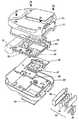
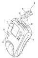
新型細動除去器の好適な実施態様を図5および6に示す。この細動除去器は従来の外部接続型細動除去器に比べて非常に小型で軽量である。好適な細動除去器の寸法(約2.2インチ×8インチ×8インチ、全容量約141立方インチ)によって、従来の外部細動除去器が収まらなかった場所に保持および/または保管することが可能である。さらに、軽量であるため(約3ポンド)、緊急の場合、細動除去器はオペレータによってより容易に移動することが可能である。
【0057】
図5および6に示すように、好適な外部細動器は、上部ケース80および下部ケース81を有する、積層された2つの部分を有するプラスチックハウジングを備える。主要プリント回路基板(PCB)86は、コンデンサ32、電極コネクタ82、PCMCIAメモリカード83およびPCMCIAメモリカードエジェクタ機構84を備える。PCMCIAメモリカード83は、PCB86上のPCMCIAメモリカードスロット95内に位置する。
【0058】
キーボードPCB85および表示PCB87は、メインPCB86と上部ケース80との間に配置されている。キーボードPCB85は細動除去器のオペレータボタンに接続され、表示PCB87は細動除去器の液晶表示装置88を動作させる。上部ケースの表示窓89によってオペレータは表示装置88を見ることが可能となる。
【0059】
絶縁体90がメインPCB86と表示PCB87との間に配置される。ハウジングが組み立てられると、封止ガスケット91が上部ケース80と下部ケース81との間のエッジを線状に取り囲む。
【0060】
バッテリハウジング92と、6つの二酸化マンガンリチウム1次電池94からなるバッテリアセンブリ99は、これらの電池がメインPCB86のコンデンサ充電回路およびその他の回路と電気的に接触するように上部ケース80に配置される。このバッテリアセンブリは、バッテリアセンブリを細動除去器に着脱するのに用いられるラッチング機構96を有している。
【0061】
このバッテリアセンブリをPCMCIAメモリカードスロットの正面に配置することによって、細動除去器のオペレータなどが、この細動除去器の充電中または動作中にPCMCIAカードにアクセスすることが防止される。このような構成により、オペレータおよび患者を偶然の衝撃から保護することが可能になり、また、動作中に誤ってPCMCIAカードを引き出してしまっても、それにより細動除去器自身にダメージが与えられる事態を回避することができる。
【0062】
本発明の細動除去器がこのように小型でかつ軽量であるのは、さまざまな設計上の特徴の組み合わせによるものである。従来技術の減衰正弦波形の代わりに切り取り型指数関数二相波形を用いることにより、波形回路にインダクタを用いなくても動作が可能である。さらに、低エネルギーの要求を満たすことができるので、従来技術の外部接続型細動除去器に比べてより小型のコンデンサおよびバッテリを用いることができる。
【0063】
バッテリのサイズをさらに小型化しようとする場合、好ましい実施態様においては、細動除去器がオンされるとすぐに、さらには心室の細動(したがって細動除去の必要)が検出される以前に、コンデンサの充電を開始するコンデンサプリチャージ回路および制御器が設けられる。ただ一度の誤操作により細動除去回路、患者あるいはオペレータにダメージがもたらされることになるレベルよりも低くプリチャージ電圧レベルは維持される。したがって、例えば好ましい実施態様におけるフルプリショックコンデンサ電圧(full preshock capacitor voltage)は1650Vであるが、プリチャージレベルは1100Vである。このプリチャージ法により、治療上のショックが表示された時に必要なバッテリからコンデンサへのエネルギー転送量を最小限にとどめることが可能になり、その結果、バッテリならびに細動除去器用変圧器の必要なサイズをより小型にすることができる。
【0064】
好ましい実施態様においては、充電可能型バッテリの代わりに6つの二酸化マンガンリチウム1次電池が用いられる。充電可能型バッテリに比べて1次電池はエネルギー密度が高く、より安価・軽量であり、また、使い捨てが可能であるので、保全も容易である。1次電池は確かに電力・エネルギーが低い特性のものであるが、切り取り型指数関数二相波形およびコンデンサプリチャージ回路を用いることにより、低い電力レベルでの動作が可能になる。
【0065】
図5および図6に示す好ましい細動除去器は、図4を参照して述べたソリッドステートの細動除去回路を有している。上述した短絡保護特性を伴うこの回路を用いることにより、高電圧装置に必要な機械スイッチの使用を避ければ、細動除去器のサイズおよび重量を低減することができる。
【0066】
図5および図6に示す細動除去器が小型でかつ軽量であるという特徴を有することにより得られるその他の利点としては、従来のCRT表示の代わりにフラットパネルLCDを用いることができる点、また、音声および機器の情報を記録するに当たっては、磁気テープレコーダあるいは紙片チャートレコーダに代わってPCMCIAメモリカードを用いることができる点が挙げられる。さらに、好ましい細動除去器は、PCMCIAカードに記憶されていた患者ECG情報の一部を、専門医師用のLCD上に表示することができるという特徴を有する。この特徴により、従来技術の外部接続型細動除去器においてストリップチャートレコーダが果たしていた役割を遂行することができる。
【0067】
軽量な細動除去器用電極を用いる設計により、全装置の重量をさらに低減することができる。例えば、従来のパドル電極の代わりに可撓性パッチ電極を用いることもできる。また、この細動除去器はエネルギーおよび電圧が低いという特徴を有しているので、電極を細動除去器に取り付けるに当たって厚いケーブルの代わりに比較的薄いワイヤを用いることができる。
【0068】
サイズの閾値150立方インチおよび重量の閾値4ポンドを共に満たしている限り、本発明の範囲内でその他の構成要素を選択し、また各構成要素についてその他の構成を用いることができる。
【0069】
本発明のどの実施態様においても、連続する単相または二相パルスにおいて交流初期極性を与えることができる。換言すれば、システムにより供給された第1の二相波形において、第1の位相が正の電圧または電流パルスであり、かつその後に第2位相の負の電圧または電流パルスが続く場合、システムにより供給される第2の二相波形は、正の第2位相電圧または電流パルスがその後に続く負の第1位相電圧または電流パルスとなる。この構成により、電極が分極する可能性、すなわち電極上で電荷がビルドアップする可能性を最小限にとどめることができる。
【0070】
上述したどの細動除去方法を用いる場合においても、初期第1位相電圧は全患者に共通とすることもできるし、また自動的選択あるいは細動除去器使用者による選択も可能である。例えば、細動除去器に対して、一つは幼児用、一つは成人用、もう一つは心臓切開手術用に用いられる3つの初期電圧設定値から任意の値を選択することができる。
【0071】
また、本発明の好ましい実施態様を二相波形に関して説明したが、単相、三相、あるいはその他の多重位相波形を用いてもよい。さらに、供給電荷以外の患者依存型電気的パラメータをモニタし、かつそれを放電中の波形整形に用いてもよい。
【0072】
以上、本発明を外部接続型細動除去器に適用されるものとして説明したが、本発明の1つ以上の局面を移植型細動除去器に適用することもできる。また、その他の改変も当業者には自明であろう。
【図面の簡単な説明】
【図1】低傾斜二相電気療法波形の概略図である。
【図2】高傾斜二相電気療法波形の概略図である。
【図3】本発明の好ましい実施態様による、細動除去器システムのブロック図である。
【図4】本発明の好ましい実施態様による、細動除去器システムの概略回路図である。
【図5】本発明の好ましい実施態様による、細動除去器の外観図である。
【図6】本発明の好ましい実施態様による、細動除去器の部分切り取り図である。
【符号の説明】
30 細動除去器システム
32 エネルギー源
34 接続機構
36 電極
38 コントローラ
40 タイマ
50 ECGシステム
52,54,56,58,60,62 スイッチ
64 レジスタ
66 スイッチ
68 電流センサ
80 上部ケース
81 下部ケース
82 電極コネクタ
83 PCMCIAメモリカード
84 PCMCIAメモリカードエジェクタ機構
85 キーボードPCB
86 メインPCB
87 表示PCB
88 液晶表示装置
89 表示窓
90 絶縁体
91 封止ガスケット
92 バッテリハウジング
94 二酸化マンガンリチウム1次電池
95 PCMCIAメモリカードスロット
96 ラッチング機構
99 バッテリアセンブリ[0001]
BACKGROUND OF THE INVENTION
This application is a continuation-in-part of US patent application SN 08 / 103,837 filed August 6, 1993, the disclosure of which is hereby incorporated by reference.
[0002]
The present invention generally relates to electrotherapy and devices for applying electrical pulses to a patient's heart. In particular, the present invention relates to a method and apparatus for shaping an electrical waveform applied by a defibrillator based on electrical parameters measured during waveform delivery. The present invention further relates to a defibrillator that meets certain critical size and weight requirements.
[0003]
[Prior art]
Sudden death from heart disease is the leading cause of death in the United States. Sudden death from heart disease is most often due to ventricular fibrillation, where the contraction of the myocardial fibers loses its integrity, thus preventing normal flow of blood to the body. The only effective treatment for ventricular fibrillation is electrical defibrillation, which applies an electrical shock to the patient's heart.
[0004]
A defibrillation shock must be applied to a patient within minutes of signs of ventricular fibrillation appearing for it to be effective. According to the survey results, the survival rate is 100% when a defibrillation shock is applied within 1 minute after ventricular fibrillation begins. If 6 minutes pass before the shock is applied, the survival rate drops to about 30%. After 12 minutes, the survival rate approaches zero.
[0005]
One method of applying a rapid defibrillation shock is the use of an implantable defibrillator. An implantable defibrillator is surgically implanted in patients who are likely to need electrical therapy in the future. The implanted defibrillator generally monitors the patient's heart activity and automatically delivers an electrotherapeutic pulse directly to the patient's heart as needed. Thus, thanks to the implantable defibrillator, the patient is able to escape from medical personnel monitoring and perform some normal activity. However, implantable defibrillators are expensive and their use is limited to only a fraction of all patients at risk of sudden death from heart disease.
[0006]
Externally connected defibrillators send electrical pulses to the patient's heart through electrodes applied to the patient's torso. Externally connected defibrillators are useful in emergency rooms, operating rooms, emergency medical vehicles, or other situations where unforeseen circumstances may arise where the patient must be immediately electrotherapy. The advantage of an externally connected defibrillator is that it can be used on a patient as needed and can be subsequently transferred to other patients.
[0007]
However, because externally connected defibrillators indirectly apply electrotherapeutic pulses to the patient's heart (ie, from the patient's skin surface rather than directly to the heart), higher energy than implantable defibrillators, Must be operated at high voltage and / or high current. Because of these high energy, high voltage and high current requirements, current externally connected defibrillators are large, heavy, especially due to the large capacitors or other energy storage media required by prior art devices. And it becomes expensive. The size and weight of prior art externally connected defibrillators have limited their benefit in emergency medical teams' rapid response.
[0008]
The defibrillator waveform, ie the time plot of the applied current or voltage pulse, is characterized by the shape, polarity, duration and number of pulse phases. Some external defibrillators provide biphasic sinusoidal pulses, but most current externally connected defibrillators provide single phase current or voltage electrotherapy pulses. On the other hand, some conventional implantable defibrillators use a truncated exponential biphasic waveform. Examples of two-phase implantable defibrillators can be found in the following US patents; US Pat. No. 4,821,723 by Baker, Jr. et al .; US Pat. No. 5,083,562 by de Coriolis et al .; US Patent by Winstrom U.S. Pat. No. 4,800,883; U.S. Pat. No. 4,850,357 by Bach, Jr .; U.S. Pat. No. 4,953,551 by Mehra et al .; and U.S. Pat. No. 5,230,336 by Fain et al.
[0009]
Because each implantable defibrillator is used for only one patient, operating parameters such as electrical pulse amplitude and total energy applied can be adjusted to optimize the effectiveness of the defibrillator. Effectively fine-tuning according to the physiology. Thus, for example, initial voltage, first phase duration and total pulse duration are implanted with a defibrillator that supplies the desired amount of energy or achieves the desired start and end voltage derivatives (ie constant slope). Can be set. Even if the implantable defibrillator can change operating parameters to compensate for changes in the defibrillator lead and / or the patient's heart impedance (as described in the Fain patent) In the case of single transplantation for a single patient, the potential impedance change range is relatively small.
[0010]
[Problems to be solved by the invention]
In contrast, externally connected defibrillator electrodes are not in direct contact with the patient's heart, and externally connected defibrillators can be used for a wide variety of patients with different physiological differences. Externally connected defibrillators must be able to operate on pulse amplitude and pulse duration parameters that will work for most patients regardless of patient physiology . For example, the impedance due to the skin between the externally connected defibrillator electrode and the patient's heart varies from patient to patient, so that the initial pulse with a certain amplitude and duration actually applies to the patient's heart. The intensity and waveform are varied. Effective pulse amplitudes and durations for low impedance patients do not always provide effective and energy efficient treatment for high impedance patients.
[0011]
Externally connected defibrillators may be exposed to extreme load conditions that can damage the waveform generation circuit in some cases. For example, if a defibrillator electrode is installed incorrectly, it can create a very low impedance current path when delivering a shock, resulting in excessive high current in the waveform circuit. there's a possibility that. Thus, externally connected defibrillators require additional designs to limit the peak current to a safe level in the waveform circuit, which is not usually a problem with implantable defibrillators.
[0012]
Conventional defibrillators do not adequately address problems due to patient differences. One prior art approach to this problem is to provide an externally connected defibrillator with multiple energy settings that the user can select. A common use for such defibrillators is to attempt defibrillation with an initial energy setting that is compatible with defibrillation for patients with average impedance and then continue to defibrillate if the initial setting is ineffective. Increase energy settings to remove motion. Repeated defibrillation attempts require additional energy and increase the risk to the patient.
[0013]
Some prior art defibrillators measure a patient's impedance or related parameters and change the shape of subsequent defibrillation shocks based on the measurement results. For example, the implantable defibrillator described in the Fain patent applies a predetermined defibrillation shock to the patient's heart in response to detecting an arrhythmia. Fain's device measures the system impedance when the shock is applied, and uses the measured impedance to change the shape of the shock applied thereafter.
[0014]
Another example of measuring and using patient impedance information in prior art defibrillators is the article "Energy, current and success of defibrillation and cardioversion" written by RE Kerber, et al. "Circulation (May 1988). The author describes an externally connected defibrillator that applies a test pulse to the patient prior to performing a defibrillation shock. The test pulse is used to measure the patient's impedance, and the defibrillator adjusts the amount of energy applied by the shock in response to the measured patient impedance. The added waveform is a damped sinusoid.
[0015]
Prior art disclosures about the use of truncated exponential biphasic waveforms in implantable defibrillators achieve acceptable defibrillation or cardioversion success rates for many patient populations Provides little guidance for the design of externally connected defibrillators. The defibrillator operating voltage and energy supply requirements affect component size, price, weight and availability. In particular, operating voltage requirements influence the choice of switch and capacitor technology. The total energy supply requirement affects the defibrillator battery and capacitor selection. Therefore, even if the implantable defibrillator and the externally connected defibrillator add the same waveform even if the waveform amplitude is different, the actual design of these two types of defibrillators Is radically different.
[0016]
[Means for Solving the Problems]
The present invention provides a defibrillator and defibrillation method that automatically compensates for differences between patients in the delivery of electrotherapy pulses for defibrillation and cardioversion. The defibrillator has an energy source that can be discharged through the electrode and provide a truncated exponential biphasic voltage or current pulse to the patient.
[0017]
A preferred embodiment of the method comprises the steps of charging the energy source to an initial level, discharging the energy source to the electrodes, transferring electrical energy to the patient in a multiphase waveform, and patient-dependent electricity during the discharging process. And monitoring the relative duration of the phases of the multi-phase waveform, including the step of monitoring the dynamic parameters and shaping the waveform of the transmitted electrical energy based on the value of the monitored electrical parameter Depends on the value of electrical parameters.
[0018]
A preferred embodiment of the device forms an electrical circuit with the energy source and the electrodes when the electrodes are attached to the patient, and two electrodes adapted to make electrical contact with the patient. Actuate the connection mechanism and the connection mechanism to transfer electrical energy from the energy source to the electrodes in a multiphase waveform that is based on electrical parameters that are monitored during the transfer of the electrical energy relative to the phase. And a controller. A preferred defibrillator has a weight of less than 4 pounds and a volume of less than 150 cubic inches, most preferably a weight of about 3 pounds or less and a volume of about 141 cubic inches.
[0019]
DETAILED DESCRIPTION OF THE INVENTION
In every patient and any implantable or externally connected defibrillator system design, there is an optimal biphasic waveform to treat certain types of arrhythmias. This principle is used when implanting a defibrillator. As described above, for the implanted defibrillator, fine adjustments are made to the patient at the time of implantation. On the other hand, externally connected defibrillators must be designed to be effective for many patients.
[0020]
For example, FIGS. 1 and 2 illustrate patient-to-patient differences that must be taken into account in externally connected defibrillator designs. These figures show a truncated exponential biphasic waveform (truncated) transmitted from an externally connected defibrillator to two patients according to the electrotherapy of the present invention for defibrillation or cardioversion. Exponential biphasic waveforms are schematically shown. In these drawings, the vertical axis represents voltage and the horizontal axis represents time. The principles discussed here are equally applicable to waveforms described with respect to current versus time.
[0021]
The waveform shown in FIG. 1 is called a low-tilt waveform, and the waveform shown in FIG. 2 is called a high-tilt waveform. The slope H is defined as a percentage as follows:
[0022]
[Expression 1]
As shown in FIGS. 1 and 2, A is an initial first phase voltage, and D is a second phase termination voltage. The first phase termination voltage B is determined by an exponential decay over the time that the initial voltage A passes through the patient, and the second phase termination voltage D is similarly determined by the exponential decay of the second phase initial voltage C. The starting voltage and the first and second phase periods in FIGS. 1 and 2 are the same. The difference between the termination voltages B and D reflects patient differences.
[0024]
For a given patient, it was confirmed that an externally applied truncated exponential biphasic waveform defibrillates at a lower voltage and lower total transmitted energy than an externally applied single phase waveform. Furthermore, in effective transmission of the cardioversion waveform, the total pulse period, the ratio of the first phase period to the second phase period, the initial voltage, the total energy, and the total tilt have a complicated relationship. It was confirmed. Therefore, design a defibrillator and defibrillation method that is effective not only on a single patient (as in most implantable defibrillator prior art) but also on a large population of patients. Is possible. Furthermore, it will be possible to meet the requirements of externally connected defibrillator designs with respect to the size, weight and capacity of the defibrillator energy source while meeting the needs of a large number of patient populations.
[0025]
So far, the more energy transferred to the patient in an electrotherapy pulse, the more likely it is to achieve the purpose of defibrillation. The low gradient two-phase waveform achieves an effective defibrillation rate with lower transmitted energy than the high gradient two-phase waveform. However, the low slope waveform is not energy efficient because most of the stored energy is not transmitted to the patient. On the other hand, a defibrillator that transmits a high-tilt two-phase waveform retains more energy than a defibrillator that transmits a low-tilt waveform while maintaining high effectiveness up to a critical tilt value. Communicate a lot. Thus, for a given capacitor, given initial voltage and fixed phase period, the total energy and peak voltage received by a high impedance patient will be lower, but the conversion characteristics per transmitted energy unit will be better. Yes, low impedance patients receive higher transmitted energy and higher peak current waveforms.
[0026]
There appears to be an optimal tilt range where high and low impedance patients receive effective and effective treatment from externally connected defibrillators. By selecting the optimal capacitor charged to a predetermined voltage, an effective and effective waveform can be transmitted to a population of patients having various physiological differences. For example, the defibrillator can be operated in an open loop, i.e., without any feedback regarding patient parameters and with a preset pulse phase period effective for a range of patients. Accordingly, the preset parameters of the waveforms shown in FIG. 1 and FIG. 2 are the initial voltage A of the first phase of the pulse, the period E of the first phase, the period G of the phase, and the period F of the second phase, respectively. . The first phase termination voltage B, the second phase initial voltage C, and the second phase termination voltage D depend on the patient's physiological parameters and the physical connection between the electrode and the patient.
[0027]
For example, if the patient impedance (ie, the total impedance between the two electrodes) is high, the amount of voltage drop (exponential decay) from the initial voltage A to the termination voltage B during time E is low in patient impedance. It becomes lower than the case (FIG. 2) (FIG. 1). This is also true for the initial and termination voltages of the second phase during time F. The values for A, E, G and F are set to optimize the effectiveness of defibrillation and / or cardioversion performed on the patient population. Thus, a high impedance patient receives a more effective low slope waveform for each unit of transmitted energy. Low impedance patients receive a higher slope waveform that transmits more stored energy and is more energy efficient.
[0028]
In order to ensure that the transmitted shock is within the optimum tilt range for a wider range of patients, the present invention provides a defibrillator waveform characteristic that depends on real-time measurement of patient-dependent electrical parameters. A defibrillation method and a defibrillation apparatus for adjustment are provided. FIG. 3 is a block diagram illustrating a preferred embodiment of the defibrillation system.
[0029]
The defibrillator system 30 includes an
[0030]
The
[0031]
The defibrillator system is controlled by the
[0032]
The
[0033]
A preferred embodiment of the defibrillator system according to the present invention is schematically illustrated in FIG. In this figure, the energy source is a
[0034]
The
[0035]
In this embodiment, the
[0036]
For the purpose of this description, it is assumed that all switches are open before discharging. It should be understood that this is not always the case. For example, the
[0037]
In response to the shock request, the controller begins to transmit the limited shock to the patient by first closing switches 52 and 54, then switch 62, and then switch 58. The
[0038]
In a preferred embodiment, the duration of the first and second phases of the biphasic waveform is determined by measuring a patient dependent electrical parameter. As described in further detail below, the parameter measured in the preferred embodiment is the time taken to transfer a predetermined amount of charge from the energy source to the patient. Charge control may provide better noise immunity than other waveform monitoring methods such as voltage or current monitoring.
[0039]
The system shown in FIG. 4 uses a
[0040]
At the end of the first phase of the waveform, the controller opens switch 62 to terminate the transmission of the shock. The
[0041]
After a short interphase period, the controller closes
[0042]
The following examples illustrate specific implementations of the method and apparatus of the present invention. The present invention is not limited to the numerical values and circuit elements described in this embodiment.
[0043]
In this embodiment, switches 52 and 54 are used as double pole, double throw mechanical relays.
[0044]
With one IBGT turned on at the same time as
[0045]
The
[0046]
A comparator coupled to the current integrator monitors the charge delivered to the patient and sends a signal to the waveform controller when the charge reaches 0.06182 coulombs (denoted Qt). The time required to reach this charge (t (Qt)) is monitored by the controller using an up / down counter that counts the scaled down reference frequency. One element of the frequency counter is a selectable 2: 3 pre-scaler. The pre-counter is set to 3 during the first phase. In this embodiment, 11 thresholds are stored in the controller and the duration of the first phase (t (Φ1)) is determined based on the time required to reach Qt. At each of the thresholds, a new value t (Φ1) is loaded until Qt is reached. If Qt is not reached within 6.35 mS, t (Φ1) is set to 12 mS. During transmission of the entire first phase, the counter operates at the scaled down frequency.
[0047]
Table 1 shows examples of Qt threshold values and t (Φ1) values.
[0048]
[Table 1]
In this embodiment, the interphase delay is set to 300 μS. At 0 μS, the first phase IGBT opens and terminates the first phase. At 250 μS, the second phase IGBT is closed. At 300 μS, the second phase SCR is closed, starting the second phase.
[0050]
In the present embodiment, the timing of the second phase is determined by the timing of the first phase. Specifically, the count value accumulated during phase 1 (2.3 mS to 12 mS) is used to control the duration of the second phase. During the second phase, the counter counted up during the first phase is counted down to 0, at which time the second phase ends. The actual duration of the second phase depends on the scale-down frequency used to stop the counter. If the first phase t (Qt) is less than 3.07 mS, the reference clock pre-counter is set to 3 to make the second phase duration equal to the first phase duration. If t (Qt) is greater than or equal to 3.07 mS, the pre-counter is set to 2 and the second phase duration is 2/3 of the first phase duration.
[0051]
In another embodiment, the measured patient-dependent electrical parameter is capacitor voltage. The comparator monitors the capacitor voltage and sends a signal to the waveform controller when the voltage drops to 1000 volts (Vt). As in the charge control implementation, the time required to reach this voltage is monitored by the controller using an up / down counter that counts the scaled down reference frequency. The first phase duration (t (Φ1)) is based on the time required to reach Vt. The method of selecting an appropriate t (Φ1) is similar to the charge control embodiment. If Vt is not reached within 6.18mS, t (Φ1) is set to 12mS. Table 2 shows the t (Vt) threshold and its associated t (Φ1).
[0052]
[Table 2]
The interphase delay and the second phase timing are the same as in the charge control method.
[0054]
We have designed a new type of defibrillator that meets certain dimensions, weight, effectiveness and safety design goals. Dimensions and weight are below the 150 cubic inch and 4 pound design threshold. Thus, this new portable defibrillator can be carried by early medical personnel and held and stored in a place such as a drug box or in a glove box of a car.
[0055]
The circuit design of the new defibrillator makes it possible to use a truncated exponential biphasic waveform as described above. By using a two-phase waveform, the defibrillator operates with the same effect as a conventional external defibrillator, while allowing it to charge and transfer with less energy at a lower voltage. . For example, compared to 200-360 joules (charged 240-439 joules) transmitted by conventional externally connected defibrillators, the new defibrillators are less than 155 joules (167 joules charged). Effectively defibrillates the patient by delivering a shock (e.g., a charged 140 joule) shock on the order of about 130 joules.
[0056]
A preferred embodiment of the new defibrillator is shown in FIGS. This defibrillator is much smaller and lighter than the conventional externally connected defibrillator. Suitable defibrillator dimensions (about 2.2 inches x 8 inches x 8 inches, total capacity about 141 cubic inches) to hold and / or store where conventional external defibrillators could not fit Is possible. In addition, because of its light weight (about 3 pounds), the defibrillator can be moved more easily by the operator in an emergency.
[0057]
As shown in FIGS. 5 and 6, a suitable external fibrillator comprises a two-part plastic housing with an
[0058]
The
[0059]
An
[0060]
A
[0061]
Placing this battery assembly in front of the PCMCIA memory card slot prevents a defibrillator operator or the like from accessing the PCMCIA card while charging or operating the defibrillator. This configuration protects the operator and patient from accidental shocks, and if the PCMCIA card is accidentally pulled out during operation, it can damage the defibrillator itself. The situation can be avoided.
[0062]
The small size and light weight of the defibrillator of the present invention is due to a combination of various design features. By using a cut-off type exponential two-phase waveform instead of the attenuated sine waveform of the prior art, operation is possible without using an inductor in the waveform circuit. In addition, since low energy requirements can be met, smaller capacitors and batteries can be used compared to prior art externally connected defibrillators.
[0063]
If the size of the battery is to be further reduced, in a preferred embodiment, as soon as the defibrillator is turned on, and even before ventricular fibrillation (and therefore need to be defibrillated) is detected. A capacitor precharge circuit and a controller for starting the charging of the capacitor are provided. The precharge voltage level is maintained below a level that would cause damage to the defibrillation circuit, the patient or the operator by a single misoperation. Thus, for example, in the preferred embodiment, the full preshock capacitor voltage is 1650V, but the precharge level is 1100V. This precharge method allows the amount of battery-to-capacitor energy transfer required when a therapeutic shock is displayed, resulting in the need for a battery and defibrillator transformer. The size can be made smaller.
[0064]
In a preferred embodiment, six lithium manganese dioxide primary batteries are used instead of rechargeable batteries. Compared to a rechargeable battery, a primary battery has a high energy density, is cheaper and lighter, and can be disposable, so that maintenance is easy. Although the primary battery has a characteristic of low power and energy, it can operate at a low power level by using a cut-off exponential function two-phase waveform and a capacitor precharge circuit.
[0065]
The preferred defibrillator shown in FIGS. 5 and 6 has the solid-state defibrillation circuit described with reference to FIG. By using this circuit with short circuit protection characteristics as described above, the size and weight of the defibrillator can be reduced if the use of mechanical switches required for high voltage devices is avoided.
[0066]
Other advantages obtained by the small and light feature of the defibrillator shown in FIGS. 5 and 6 include that a flat panel LCD can be used instead of a conventional CRT display, and In recording audio and device information, a PCMCIA memory card can be used instead of a magnetic tape recorder or a paper chart recorder. Furthermore, the preferred defibrillator has the feature that a portion of the patient ECG information stored on the PCMCIA card can be displayed on the specialist physician's LCD. This feature makes it possible to perform the role played by the strip chart recorder in the externally connected defibrillator of the prior art.
[0067]
A design that uses a light defibrillator electrode can further reduce the weight of the entire device. For example, a flexible patch electrode can be used instead of a conventional paddle electrode. Also, the defibrillator is characterized by low energy and voltage, so a relatively thin wire can be used in place of a thick cable to attach the electrode to the defibrillator.
[0068]
Other components can be selected and other configurations can be used for each component as long as both the size threshold of 150 cubic inches and the weight threshold of 4 pounds are met.
[0069]
In any embodiment of the present invention, alternating initial polarity can be provided in a continuous single phase or biphasic pulse. In other words, in the first biphasic waveform supplied by the system, if the first phase is a positive voltage or current pulse and is followed by a second phase negative voltage or current pulse, then the system The supplied second biphasic waveform is a negative first phase voltage or current pulse followed by a positive second phase voltage or current pulse. With this configuration, the possibility that the electrode is polarized, that is, the possibility that charges are built up on the electrode, can be minimized.
[0070]
Regardless of which defibrillation method described above is used, the initial first phase voltage can be common to all patients, or can be automatically selected or selected by the defibrillator user. For example, for the defibrillator, an arbitrary value can be selected from three initial voltage setting values, one for infants, one for adults, and one for cardiotomy.
[0071]
Also, although the preferred embodiment of the present invention has been described with reference to a two-phase waveform, single-phase, three-phase, or other multiple phase waveforms may be used. In addition, patient dependent electrical parameters other than the supply charge may be monitored and used for waveform shaping during discharge.
[0072]
While the present invention has been described as applied to an externally connected defibrillator, one or more aspects of the present invention can also be applied to an implantable defibrillator. Other modifications will be apparent to those skilled in the art.
[Brief description of the drawings]
FIG. 1 is a schematic diagram of a low-gradient biphasic electrotherapy waveform.
FIG. 2 is a schematic diagram of a high gradient two-phase electrotherapy waveform.
FIG. 3 is a block diagram of a defibrillator system according to a preferred embodiment of the present invention.
FIG. 4 is a schematic circuit diagram of a defibrillator system according to a preferred embodiment of the present invention.
FIG. 5 is an external view of a defibrillator according to a preferred embodiment of the present invention.
FIG. 6 is a partial cutaway view of a defibrillator according to a preferred embodiment of the present invention.
[Explanation of symbols]
30 Defibrillator system
32 Energy sources
34 Connection mechanism
36 electrodes
38 Controller
40 timer
50 ECG system
52, 54, 56, 58, 60, 62 switches
64 registers
66 switch
68 Current sensor
80 Upper case
81 Lower case
82 electrode connector
83 PCMCIA memory card
84 PCMCIA memory card ejector mechanism
85 keyboard PCB
86 Main PCB
87 Display PCB
88 Liquid crystal display
89 Display window
90 insulator
91 Sealing gasket
92 Battery housing
94 Lithium manganese dioxide primary battery
95 PCMCIA memory card slot
96 Latching mechanism
99 battery assembly
Claims (2)
Translated fromJapanese誤動作により細動除去回路、患者又はオペレータにダメージがもたらされ得るレベルより低いプリチャージ電圧レベルまで該エネルギー源に電荷を充電する手段と、
該患者にショックを与える必要性を判断する手段と、
該患者にショックを与える必要性を判断した後に、該プリチャージ電圧レベルよりも高い第2のレベルまで該エネルギー源に電荷を充電する手段と、
該エネルギー源に接続された電極の間で、該エネルギー源の電荷を放電する手段とを有する外部接続型細動除去器。Energy sources,
Defibrillation circuitry, means for charging the energy source to aprecharge voltage level below a level that can cause damage to the patient or operator by malfunctioning ;
Means for determining a need to provide a shock tothe patient,
Means for charging the energy source to a second level higher than theprecharge voltage level after determining the need to shock the patient;
An externally connected defibrillator having means for discharging the charge of the energy source between electrodes connected to the energy source.
Applications Claiming Priority (4)
| Application Number | Priority Date | Filing Date | Title |
|---|---|---|---|
| US10383793A | 1993-08-06 | 1993-08-06 | |
| US08/103.837 | 1993-08-06 | ||
| US08/227,553US5607454A (en) | 1993-08-06 | 1994-04-14 | Electrotherapy method and apparatus |
| US08/227.553 | 1994-04-14 |
Related Parent Applications (1)
| Application Number | Title | Priority Date | Filing Date |
|---|---|---|---|
| JP11238564ADivisionJP2000051374A (en) | 1993-08-06 | 1999-08-25 | External connection type defibrillator |
Publications (2)
| Publication Number | Publication Date |
|---|---|
| JP2003038662A JP2003038662A (en) | 2003-02-12 |
| JP3828054B2true JP3828054B2 (en) | 2006-09-27 |
Family
ID=26800907
Family Applications (4)
| Application Number | Title | Priority Date | Filing Date |
|---|---|---|---|
| JP7506957APendingJPH09500309A (en) | 1993-08-06 | 1994-07-19 | Electrotherapy method and apparatus |
| JP11238564APendingJP2000051374A (en) | 1993-08-06 | 1999-08-25 | External connection type defibrillator |
| JP2002211676AExpired - LifetimeJP3828054B2 (en) | 1993-08-06 | 2002-07-19 | External defibrillator |
| JP2003067269AExpired - LifetimeJP4159384B2 (en) | 1993-08-06 | 2003-03-12 | Electrical therapy device |
Family Applications Before (2)
| Application Number | Title | Priority Date | Filing Date |
|---|---|---|---|
| JP7506957APendingJPH09500309A (en) | 1993-08-06 | 1994-07-19 | Electrotherapy method and apparatus |
| JP11238564APendingJP2000051374A (en) | 1993-08-06 | 1999-08-25 | External connection type defibrillator |
Family Applications After (1)
| Application Number | Title | Priority Date | Filing Date |
|---|---|---|---|
| JP2003067269AExpired - LifetimeJP4159384B2 (en) | 1993-08-06 | 2003-03-12 | Electrical therapy device |
Country Status (10)
| Country | Link |
|---|---|
| US (3) | US5607454A (en) |
| EP (2) | EP0712321B1 (en) |
| JP (4) | JPH09500309A (en) |
| AT (1) | ATE263598T1 (en) |
| AU (1) | AU7367294A (en) |
| CA (1) | CA2168978A1 (en) |
| DE (2) | DE69433686T2 (en) |
| ES (1) | ES2215998T3 (en) |
| NO (1) | NO960470L (en) |
| WO (1) | WO1995005215A2 (en) |
Families Citing this family (251)
| Publication number | Priority date | Publication date | Assignee | Title |
|---|---|---|---|---|
| US5601612A (en)* | 1993-08-06 | 1997-02-11 | Heartstream, Inc. | Method for applying a multiphasic waveform |
| US5540723A (en) | 1993-10-06 | 1996-07-30 | Duke University | Method and apparatus for delivering an optimum shock duration in treating cardiac arrhythmias |
| US6853859B1 (en)* | 1994-05-31 | 2005-02-08 | Galvani, Ltd. | Electrical cardiac output forcer |
| US6185457B1 (en)* | 1994-05-31 | 2001-02-06 | Galvani, Ltd. | Method and apparatus for electrically forcing cardiac output in an arrhythmia patient |
| US5691881A (en)* | 1995-05-16 | 1997-11-25 | Hewlett-Packard Company | Electronic device having E-PAC chassis for spatial arrangement of components and cable organization including channel with retaining wall preventing cable from dislodging from an edge connector |
| US5620465A (en)* | 1995-06-08 | 1997-04-15 | Survivalink Corporation | External defibrillator for producing and testing biphasic waveforms |
| US5797969A (en)* | 1995-08-01 | 1998-08-25 | Survivalink Corporation | One button lid activated automatic external defibrillator |
| US5645571B1 (en)* | 1995-08-01 | 1999-08-24 | Surviva Link Corp | Automated external defibrillator with lid activated self-test system |
| US5967817A (en) | 1995-11-21 | 1999-10-19 | Heartstream, Inc. | Medical connector apparatus |
| WO1997031680A1 (en)* | 1996-03-01 | 1997-09-04 | Heartstream, Inc. | Electrotherapy method and apparatus |
| EP0892656A4 (en) | 1996-04-12 | 2000-08-30 | Survivalink Corp | External defibrillator having low capacitance and small time constant |
| US5899924A (en) | 1996-04-12 | 1999-05-04 | Survivalink Corporation | Single capacitor truncated damped sinusoidal defibrillation waveform |
| US5741306A (en)* | 1996-05-23 | 1998-04-21 | Lifecor, Inc. | Patient-worn energy delivery apparatus |
| US5909138A (en)* | 1996-06-27 | 1999-06-01 | Survivalink Corporation | Fast isolated IGBT driver for high voltage switching circuitry |
| US5836972A (en)* | 1996-06-27 | 1998-11-17 | Survivalink Corp. | Parallel charging of mixed capacitors |
| US5891172A (en)* | 1996-06-27 | 1999-04-06 | Survivalink Corporation | High voltage phase selector switch for external defibrillators |
| US5991658A (en)* | 1996-07-01 | 1999-11-23 | Survivalink Corporation | Continual waveform shape reforming method and apparatus for transchest resistance dynamics |
| US6411846B1 (en) | 1999-08-26 | 2002-06-25 | Survivalink Corporation | Method and apparatus for delivering a biphasic defibrillation pulse with variable energy |
| US5968080A (en)* | 1996-07-01 | 1999-10-19 | Survivalink Corporation | Method for determining the second phase of external defibrillator devices |
| US6263239B1 (en) | 1996-07-01 | 2001-07-17 | Survivalink Corporation | Method and apparatus for determining the second phase of defibrillator devices |
| US5893049A (en)* | 1996-08-06 | 1999-04-06 | Pacesetter, Inc. | Rapid response voltage threshold determination circuit for electrophysiology diagnostic device |
| JP4108758B2 (en) | 1996-12-18 | 2008-06-25 | ズィーエムディー コーポレーション | Current waveform of electrotherapy |
| US5797968A (en)* | 1996-12-18 | 1998-08-25 | Zmd Corporation | Electrotherapy circuit for producing current waveform with sawtooth ripple |
| US6096063A (en)* | 1996-12-18 | 2000-08-01 | Zmd Corporation | Electrotherapy circuit having controlled current discharge based on patient-dependent electrical parameter |
| US5800462A (en)* | 1996-12-18 | 1998-09-01 | Zmd Corporation | Electrotherapy circuit for producing therapeutic discharge waveform based on high-current sensing pulse |
| US5769872A (en)* | 1996-12-18 | 1998-06-23 | Zmd Corporation | Electrotherapy circuit and method for shaping current waveforms |
| US5904706A (en)* | 1996-12-18 | 1999-05-18 | Zmd Corporation | Method and apparatus for producing electrotherapy current waveform with ripple |
| US5800463A (en)* | 1996-12-18 | 1998-09-01 | Zmd Corporation | Electrotherapy circuit having controlled peak current |
| US5733310A (en)* | 1996-12-18 | 1998-03-31 | Zmd Corporation | Electrotherapy circuit and method for producing therapeutic discharge waveform immediately following sensing pulse |
| US6175765B1 (en) | 1997-03-05 | 2001-01-16 | Medtronic Physio-Control Manufacturing Corp. | H-bridge circuit for generating a high-energy biphasic waveform in an external defibrillator |
| US6963773B2 (en)* | 1997-03-05 | 2005-11-08 | Medtronic Physio-Control Manufacturing Corp. | H-bridge circuit for generating a high-energy biphasic waveform in an external defibrillator using single SCR and IGBT switches in an integrated package |
| US5824017A (en)* | 1997-03-05 | 1998-10-20 | Physio-Control Corporation | H-bridge circuit for generating a high-energy biphasic waveform in an external defibrillator |
| US5873893A (en)* | 1997-03-05 | 1999-02-23 | Physio-Control Corporation | Method and apparatus for verifying the integrity of an output circuit before and during application of a defibrillation pulse |
| US6148233A (en)* | 1997-03-07 | 2000-11-14 | Cardiac Science, Inc. | Defibrillation system having segmented electrodes |
| WO1998044990A1 (en)* | 1997-04-08 | 1998-10-15 | Survivlink Corporation | Aami specification optimized truncated exponential waveform |
| US6088616A (en)* | 1997-04-10 | 2000-07-11 | Survivalink Corporation | Field programmable automated external defibrillator |
| IL131821A (en)* | 1997-04-18 | 2004-07-25 | Physio Control Mfg Corp | Heart defibrillator apparatus and method |
| US5899925A (en)* | 1997-08-07 | 1999-05-04 | Heartstream, Inc. | Method and apparatus for aperiodic self-testing of a defibrillator |
| US5931791A (en)* | 1997-11-05 | 1999-08-03 | Instromedix, Inc. | Medical patient vital signs-monitoring apparatus |
| DE69829358T2 (en) | 1997-11-06 | 2006-04-06 | Koninklijke Philips Electronics N.V. | EXTERNAL DEFIBRILLATOR WITH CPR INDICATIONS AND WITH ACLS INDICATIONS |
| US5974339A (en)* | 1997-11-26 | 1999-10-26 | Procath Corporation | High energy defibrillator employing current control circuitry |
| USD414870S (en) | 1998-01-02 | 1999-10-05 | Instromedix, Inc. | Vital signs monitor |
| US6083246A (en)* | 1998-04-08 | 2000-07-04 | Survivalink Corporation | Lid open detection circuit for automated external defibrillators |
| US6539255B1 (en) | 1998-07-16 | 2003-03-25 | Cardiac Science, Inc. | Full-tilt exponential defibrillation waveform |
| US6693431B1 (en) | 1998-08-28 | 2004-02-17 | Koninklijke Philips Electronics N.V. | Battery system and method of determining battery condition |
| US6108578A (en) | 1998-09-02 | 2000-08-22 | Heartstream, Inc. | Configurable arrhythmia analysis algorithm |
| US6173204B1 (en) | 1998-10-13 | 2001-01-09 | Physio-Control Manufacturing Corporation | Semiconductor assisted relay in a biphasic defibrillator |
| US6212429B1 (en) | 1998-10-13 | 2001-04-03 | Physio-Control Manufacturing Corporation | Method and apparatus for converting a monophasic defibrillator to a biphasic defibrillator |
| US6208895B1 (en)* | 1998-10-13 | 2001-03-27 | Physio-Control Manufacturing Corporation | Circuit for performing external pacing and biphasic defibrillation |
| US6208896B1 (en) | 1998-11-13 | 2001-03-27 | Agilent Technologies, Inc. | Method and apparatus for providing variable defibrillation waveforms using switch-mode amplification |
| US6887244B1 (en)* | 1998-12-16 | 2005-05-03 | Medtronic, Inc. | Cordless surgical handpiece with disposable battery; and method |
| FR2788699B1 (en) | 1999-01-27 | 2001-05-25 | Bruker Medical Sa | PULSES OR SERIES OF DEFIBRILLATION PULSES AND DEVICE FOR GENERATING THE SAME |
| AU2568200A (en)* | 1999-02-08 | 2000-08-29 | James Allen | Apparatus for determining when a patient is susceptible to defibrillation |
| US6208898B1 (en)* | 1999-03-25 | 2001-03-27 | Agilent Technologies, Inc. | Impedance estimation with dynamic waveform control in an electrotherapy apparatus |
| US6234816B1 (en) | 1999-03-30 | 2001-05-22 | Agilant Technologies, Inc. | Medical connector apparatus |
| US6266561B1 (en) | 1999-04-01 | 2001-07-24 | Agilent Technologies, Inc. | Method of adjusting electrotherapy in response to an arrhythmia |
| US6241751B1 (en) | 1999-04-22 | 2001-06-05 | Agilent Technologies, Inc. | Defibrillator with impedance-compensated energy delivery |
| US6266562B1 (en) | 1999-04-30 | 2001-07-24 | Agilent Technologies, Inc. | Defibrillator with automated test load |
| US6317635B1 (en) | 1999-06-30 | 2001-11-13 | Dennis E. Ochs | Sensor responsive electrotherapy apparatus |
| US20020193844A1 (en)* | 1999-07-08 | 2002-12-19 | Michelson Steve A. | Combination electrode-battery assembly for a miniature wireless transcutaneous electrical neuro or muscular-stimulation unit |
| US6445955B1 (en) | 1999-07-08 | 2002-09-03 | Stephen A. Michelson | Miniature wireless transcutaneous electrical neuro or muscular-stimulation unit |
| US20020019652A1 (en) | 1999-07-08 | 2002-02-14 | Cyclotec Advanced Medical Technologies | Two part tens bandage |
| US6298266B1 (en)* | 1999-08-10 | 2001-10-02 | Intermedics Inc. | Methods and apparatus for treating fibrillation and creating defibrillation waveforms |
| US6738664B1 (en) | 1999-09-24 | 2004-05-18 | The Curators Of The University Of Missouri | Method of and apparatus for atrial and ventricular defibrillation or cardioversion with an electrical waveform optimized in the frequency domain |
| US6353758B1 (en) | 1999-09-29 | 2002-03-05 | Bradford E Gliner | Apparatus and method for delivering a low energy therapeutic pulse to a patient |
| US6438415B1 (en) | 1999-10-01 | 2002-08-20 | Daniel J Powers | Method and apparatus for controlling the operation and functionality of an electrotherapy device |
| US6314320B1 (en)* | 1999-10-01 | 2001-11-06 | Daniel J Powers | Method and apparatus for selectively inactivating AED functionality |
| US6546287B1 (en) | 1999-10-08 | 2003-04-08 | Purdue Research Foundation | Controlled-power defibrillator and method of defibrillation |
| US6360120B1 (en) | 1999-10-13 | 2002-03-19 | Daniel J Powers | Method and apparatus for transferring patient data generated by an external defibrillator |
| US6304783B1 (en) | 1999-10-14 | 2001-10-16 | Heartstream, Inc. | Defibrillator system including a removable monitoring electrodes adapter and method of detecting the monitoring adapter |
| US6990371B2 (en) | 1999-10-14 | 2006-01-24 | Koninklijke Philips Electronics N.V. | Method and apparatus for providing on-screen incident review in an AED |
| DE10064965B4 (en)* | 1999-12-29 | 2007-01-04 | Metrax Gmbh | Medical device for applying electrical energy to a patient |
| US6647290B2 (en) | 2000-01-18 | 2003-11-11 | Koninklijke Philips Electronics N.V. | Charge-based defibrillation method and apparatus |
| WO2001060454A1 (en)* | 2000-02-18 | 2001-08-23 | Heartsine Technologies, Inc. | A defibrillator |
| US6421563B1 (en)* | 2000-03-01 | 2002-07-16 | Medtronic Physio-Control Manufacturing Corp. | Solid-state multiphasic defibrillation circuit |
| JP4221687B2 (en) | 2000-03-08 | 2009-02-12 | 日本光電工業株式会社 | ELECTROTHERAPY DEVICE AND ITS ELECTRIC ENERGY OUTPUT METHOD |
| US6441582B1 (en) | 2000-03-29 | 2002-08-27 | Koninklijke Phillips Electronics N.V. | Battery arrangement for improved defibrillator safety |
| US7016726B1 (en) | 2000-05-17 | 2006-03-21 | Koninklijke Philips Electronics N.V. | Smart medical connector system and method of use |
| US7463922B1 (en) | 2000-07-13 | 2008-12-09 | Koninklijke Philips Electronics, N.V. | Circuit and method for analyzing a patient's heart function using overlapping analysis windows |
| US6778860B2 (en)* | 2001-11-05 | 2004-08-17 | Cameron Health, Inc. | Switched capacitor defibrillation circuit |
| US6721597B1 (en) | 2000-09-18 | 2004-04-13 | Cameron Health, Inc. | Subcutaneous only implantable cardioverter defibrillator and optional pacer |
| US6754528B2 (en) | 2001-11-21 | 2004-06-22 | Cameraon Health, Inc. | Apparatus and method of arrhythmia detection in a subcutaneous implantable cardioverter/defibrillator |
| US6539258B1 (en) | 2000-10-06 | 2003-03-25 | Medtronic Physio-Control Manufacturing Corp. | Energy adjusting circuit for producing an ultra-low energy defibrillation waveform with fixed pulse width and fixed tilt |
| US6556864B1 (en) | 2000-11-13 | 2003-04-29 | Koninklijke Philips Electronics N.V. | Object activated defibrillator |
| US6675051B2 (en) | 2000-12-22 | 2004-01-06 | Koninklijke Philips Electronics N.V. | See-through electrode-pad package and method for using a storage system that includes the package |
| US6662056B2 (en) | 2000-12-22 | 2003-12-09 | Koninklijke Philips Electronics N.V. | Cartridge for storing an electrode pad |
| US6493581B2 (en) | 2000-12-28 | 2002-12-10 | Koninklijke Philips Electronics N.V. | System and method for rapid recruitment of widely distributed easily operated automatic external defibrillators |
| US6871093B2 (en) | 2000-12-28 | 2005-03-22 | Koninklijke Philips Electronics N.V. | Reporting the status for an external defibrillator with an audible report in response to a specified user input |
| US6668193B2 (en) | 2001-01-04 | 2003-12-23 | Cardiac Pacemakers, Inc. | Method and apparatus for cardiac shock therapy |
| US6546286B2 (en) | 2001-02-27 | 2003-04-08 | Koninklijke Philips Electronics N.V. | Battery-less, human-powered electrotherapy device |
| US6935889B2 (en)* | 2001-02-28 | 2005-08-30 | Koninklijke Philips Electronics N.V. | Electrode-pad package that is removable from an electrode-pad lead and method for opening the package |
| US6553257B2 (en) | 2001-03-13 | 2003-04-22 | Koninklijke Philips Electronics N.V. | Interactive method of performing cardipulmonary resuscitation with minimal delay to defibrillation shocks |
| US6560485B2 (en) | 2001-03-27 | 2003-05-06 | Koninklijke Philips Electronics N.V. | Four contact identification defibrillator electrode system |
| US6650936B2 (en) | 2001-04-23 | 2003-11-18 | Medtronic Physio-Control Manufacturing Corporation. | Method and apparatus for delivering electrotherapy having an equivalent probability of success for different patients |
| US6671547B2 (en) | 2001-06-13 | 2003-12-30 | Koninklijke Philips Electronics N.V. | Adaptive analysis method for an electrotherapy device and apparatus |
| US6625487B2 (en) | 2001-07-17 | 2003-09-23 | Koninklijke Philips Electronics N.V. | Bioelectrical impedance ECG measurement and defibrillator implementing same |
| US6567698B2 (en) | 2001-07-17 | 2003-05-20 | Koninklijke Philips Electronics N.V. | System and method for applying sequential low energy defibrillation pulses |
| US20030028219A1 (en) | 2001-07-20 | 2003-02-06 | Powers Daniel J. | Modular medical device, base unit and module thereof, and automated external defibrillator (AED), methods for assembling and using the AED |
| US7848805B2 (en)* | 2001-07-20 | 2010-12-07 | Koninklijke Philips Electronics N.V. | Modular medical device, base unit and module thereof, and automated external defibrillator (AED), methods for assembling and using the AED |
| US20030125771A1 (en)* | 2001-08-01 | 2003-07-03 | Medical Research Laboratories, Inc. | Multiphasic defibrillator utilizing controlled energy pulses |
| USD452012S1 (en) | 2001-08-14 | 2001-12-11 | Barney L. Phillips | Medical monitoring device |
| WO2003020362A2 (en)* | 2001-08-31 | 2003-03-13 | Access Cardiosystems, Inc. | Automated external defibrillator (aed) system |
| US7016727B2 (en) | 2001-11-05 | 2006-03-21 | Koninklijke Philips Electronics N.V. | Cartridge having a power source and electrode pad for defibrillator having a rechargeable battery |
| US6813517B2 (en) | 2001-11-06 | 2004-11-02 | Medtronic Physio-Control Corp. | Configuring defibrillator energy dosing |
| US7151963B2 (en)* | 2001-12-03 | 2006-12-19 | Medtronic, Inc. | Control of arbitrary waveforms for constant delivered energy |
| US6662046B2 (en) | 2001-12-21 | 2003-12-09 | Koninklijke Philips Electronics N.V. | Defibrillator with automatic turn on, defibrillator storage case, and related system and method |
| US6965796B2 (en)* | 2002-03-11 | 2005-11-15 | Medtronic Physio-Control Manufacturing Corp. | Method and apparatus for self-test of defibrillation and pacing circuits including a patient isolation switch |
| US7096062B2 (en)* | 2002-03-11 | 2006-08-22 | Medtronic Physio-Control Manufacturing Corp. | Method for self-test of defibrillation and pacing circuits including a patient isolation switch |
| US6980859B2 (en) | 2002-03-22 | 2005-12-27 | Koninklijke Philips Electronics N.V. | Automated external defibrillator with a plurality of power sources |
| US8417327B2 (en)* | 2002-06-20 | 2013-04-09 | Physio-Control, Inc. | Variable frequency impedance measurement |
| US6968230B2 (en) | 2002-06-26 | 2005-11-22 | Medtronic Physio-Control Manufacturing Corp | H-bridge circuit for generating a high-energy biphasic and external pacing waveform in an external defibrillator |
| EP1382369A1 (en)* | 2002-07-20 | 2004-01-21 | Schiller AG | Device for electrotherapy and method of testing and operating the same |
| US20040044371A1 (en)* | 2002-09-04 | 2004-03-04 | Medtronic Physio-Control Manufacturing Corp. | Defibrillator with H-bridge output circuit referenced to common ground |
| US6873133B1 (en)* | 2002-09-11 | 2005-03-29 | Medtronic Physio-Control Manufacturing Corporation | Defibrillator with a reconfigurable battery module |
| US7920917B2 (en)* | 2003-07-17 | 2011-04-05 | Physio-Control, Inc. | External defibrillator and methods for operating the external defibrillator |
| US7242979B1 (en) | 2002-09-20 | 2007-07-10 | Medtronic Physio-Control Manufacturing Corporation | External defibrillator and methods for operating the external defibrillator |
| US20040064154A1 (en)* | 2002-09-30 | 2004-04-01 | Norton John D. | Apparatus and method for optimizing capacitor charge in a medical device |
| US20040088011A1 (en)* | 2002-10-31 | 2004-05-06 | Koninklijke Philips Electronics N.V. | Defibrillation circuit that can compensate for a variation in a patient parameter and related defibrillator and method |
| US7272441B1 (en) | 2002-11-13 | 2007-09-18 | Medtronic Physio-Control Manufacturing Corp. | External defibrillator and methods for operating the external defibrillator |
| US7174208B2 (en)* | 2002-12-03 | 2007-02-06 | Medtronic, Inc. | Slow rise defibrillation waveforms to minimize stored energy for a pulse modulated circuit and maximize charge transfer to myocardial membrane |
| US7617007B2 (en)* | 2003-06-04 | 2009-11-10 | Synecor Llc | Method and apparatus for retaining medical implants within body vessels |
| US7082336B2 (en) | 2003-06-04 | 2006-07-25 | Synecor, Llc | Implantable intravascular device for defibrillation and/or pacing |
| US8239045B2 (en)* | 2003-06-04 | 2012-08-07 | Synecor Llc | Device and method for retaining a medical device within a vessel |
| CA2527909A1 (en) | 2003-06-04 | 2005-01-06 | Synecor Llc | Intravascular electrophysiological system and methods |
| US20050049654A1 (en)* | 2003-08-28 | 2005-03-03 | Peter Lathrop | Ultralight pre-programmed microprocessor based electrotherapy technology |
| US20050065558A1 (en)* | 2003-09-19 | 2005-03-24 | Powers Daniel J. | External defibrillator having a removable battery pack using off-the-shelf cells |
| US20050070983A1 (en)* | 2003-09-25 | 2005-03-31 | Rugnetta Jaime L. | Lead system having lead body with minimized cross-section |
| EP1673144B1 (en)* | 2003-09-30 | 2008-10-15 | Koninklijke Philips Electronics N.V. | Identification system for defibrillator electrode package |
| USD499183S1 (en) | 2003-10-01 | 2004-11-30 | Defibtech, Llc | Enclosure for an automatic external defibrillator |
| US8014859B2 (en)* | 2003-10-02 | 2011-09-06 | Defibtech, Llc | External defibrillator enclosure with accessory storage slot |
| WO2005034154A2 (en)* | 2003-10-06 | 2005-04-14 | Koninklijke Philips Electronics, N.V. | Apparatus and method for packaging a capacitor |
| EP1701766A2 (en)* | 2003-12-12 | 2006-09-20 | Synecor, LLC | Implantable medical device having pre-implant exoskeleton |
| AU2005212341B2 (en)* | 2004-02-10 | 2011-11-24 | Synecor, Llc. | Intravascular delivery system for therapeutic agents |
| KR20060134064A (en)* | 2004-02-19 | 2006-12-27 | 코닌클리케 필립스 일렉트로닉스 엔.브이. | Method and apparatus for broadcasting audible information induced from extracorporeal ventricular defibrillators |
| US7346382B2 (en) | 2004-07-07 | 2008-03-18 | The Cleveland Clinic Foundation | Brain stimulation models, systems, devices, and methods |
| US7224575B2 (en) | 2004-07-16 | 2007-05-29 | Cardiac Pacemakers, Inc. | Method and apparatus for high voltage aluminum capacitor design |
| US20060111750A1 (en)* | 2004-11-24 | 2006-05-25 | Bowers Kyle R | Automated external defibrillator (AED) with discrete sensing pulse for use in configuring a therapeutic biphasic waveform |
| US8401637B2 (en)* | 2004-11-24 | 2013-03-19 | Galvani, Ltd. | Medium voltage therapy applications in treating cardiac arrest |
| US7904152B2 (en)* | 2004-12-09 | 2011-03-08 | Physio-Control, Inc. | External defibrillator with charge advisory algorithm |
| CN101084040B (en) | 2004-12-20 | 2012-12-05 | 皇家飞利浦电子股份有限公司 | Automatic external defibrillator for adult and pediatric patients |
| FR2879937B1 (en)* | 2004-12-23 | 2008-01-11 | Schiller Medical Sas | DEFIBRILLATOR WHERE THE DISCHARGE CIRCUIT IS SECURED AND HAS AN H-BRIDGE |
| CN101098730A (en) | 2005-01-05 | 2008-01-02 | 皇家飞利浦电子股份有限公司 | Defibrillator event data with time correlation |
| JP5047942B2 (en)* | 2005-03-29 | 2012-10-10 | コーニンクレッカ フィリップス エレクトロニクス エヌ ヴィ | Impedance compensated defibrillator with energy supply function |
| US9339650B2 (en) | 2005-04-13 | 2016-05-17 | The Cleveland Clinic Foundation | Systems and methods for neuromodulation using pre-recorded waveforms |
| US8112154B2 (en)* | 2005-04-13 | 2012-02-07 | The Cleveland Clinic Foundation | Systems and methods for neuromodulation using pre-recorded waveforms |
| CN105013085A (en)* | 2005-08-04 | 2015-11-04 | 赛昂国际医疗控股有限公司 | automatic external defibrillator (AED) with wireless communication |
| US7457662B2 (en)* | 2005-09-09 | 2008-11-25 | Cardiac Science Corporation | Method and apparatus for variable capacitance defibrillation |
| US7821766B2 (en)* | 2007-04-19 | 2010-10-26 | Taser International, Inc. | Systems and methods for pulse delivery |
| US8150511B2 (en)* | 2006-06-29 | 2012-04-03 | Pacesetter, Inc. | Systems and methods for determining an optimal defibrillation shock waveform |
| US8024037B2 (en)* | 2006-08-01 | 2011-09-20 | Kumar Uday N | External defibrillator |
| US8170662B2 (en)* | 2006-08-03 | 2012-05-01 | Cardiac Pacemakers, Inc. | Method and apparatus for charging partitioned capacitors |
| US8761875B2 (en)* | 2006-08-03 | 2014-06-24 | Cardiac Pacemakers, Inc. | Method and apparatus for selectable energy storage partitioned capacitor |
| US8154853B2 (en)* | 2006-08-03 | 2012-04-10 | Cardiac Pacemakers, Inc. | Method and apparatus for partitioned capacitor |
| US20100131024A1 (en)* | 2006-10-06 | 2010-05-27 | Peter Lathrop | Electrotherapy orthopedic device |
| US8369944B2 (en) | 2007-06-06 | 2013-02-05 | Zoll Medical Corporation | Wearable defibrillator with audio input/output |
| US7962212B2 (en)* | 2007-08-02 | 2011-06-14 | Cameron Health, Inc. | Multiple battery configurations in an implantable medical device |
| WO2009036316A1 (en) | 2007-09-14 | 2009-03-19 | Corventis, Inc. | Energy management, tracking and security for adherent patient monitor |
| US8116841B2 (en) | 2007-09-14 | 2012-02-14 | Corventis, Inc. | Adherent device with multiple physiological sensors |
| US9186089B2 (en) | 2007-09-14 | 2015-11-17 | Medtronic Monitoring, Inc. | Injectable physiological monitoring system |
| WO2009036327A1 (en) | 2007-09-14 | 2009-03-19 | Corventis, Inc. | Adherent device for respiratory monitoring and sleep disordered breathing |
| EP3922171A1 (en) | 2007-09-14 | 2021-12-15 | Medtronic Monitoring, Inc. | Adherent cardiac monitor with advanced sensing capabilities |
| WO2009036369A1 (en) | 2007-09-14 | 2009-03-19 | Corventis, Inc. | System and methods for wireless body fluid monitoring |
| EP2194858B1 (en) | 2007-09-14 | 2017-11-22 | Corventis, Inc. | Medical device automatic start-up upon contact to patient tissue |
| JP5205389B2 (en)* | 2007-10-11 | 2013-06-05 | パナソニック株式会社 | High voltage generation circuit, puncture device and blood test device |
| US8260425B2 (en) | 2007-10-12 | 2012-09-04 | Intelect Medical, Inc. | Deep brain stimulation system with inputs |
| US8812123B2 (en)* | 2007-10-17 | 2014-08-19 | Intelect Medical, Inc. | Patient programmer with input and sensing capabilities |
| US9220889B2 (en) | 2008-02-11 | 2015-12-29 | Intelect Medical, Inc. | Directional electrode devices with locating features |
| US8019440B2 (en) | 2008-02-12 | 2011-09-13 | Intelect Medical, Inc. | Directional lead assembly |
| EP2257216B1 (en) | 2008-03-12 | 2021-04-28 | Medtronic Monitoring, Inc. | Heart failure decompensation prediction based on cardiac rhythm |
| WO2009146214A1 (en) | 2008-04-18 | 2009-12-03 | Corventis, Inc. | Method and apparatus to measure bioelectric impedance of patient tissue |
| US9272153B2 (en) | 2008-05-15 | 2016-03-01 | Boston Scientific Neuromodulation Corporation | VOA generation system and method using a fiber specific analysis |
| JP5559810B2 (en) | 2008-12-15 | 2014-07-23 | コーヴェンティス,インク. | Patient monitoring system and method |
| US20100268292A1 (en)* | 2009-04-16 | 2010-10-21 | Vishay Sprague, Inc. | Hermetically sealed wet electrolytic capacitor |
| US10028721B2 (en) | 2009-06-19 | 2018-07-24 | Koninklijke Philips N.V. | Biphasic defibrillator waveform with adjustable second phase tilt |
| US8483822B1 (en) | 2009-07-02 | 2013-07-09 | Galvani, Ltd. | Adaptive medium voltage therapy for cardiac arrhythmias |
| WO2011025865A1 (en) | 2009-08-27 | 2011-03-03 | The Cleveland Clinic Foundation | System and method to estimate region of tissue activation |
| WO2011050283A2 (en) | 2009-10-22 | 2011-04-28 | Corventis, Inc. | Remote detection and monitoring of functional chronotropic incompetence |
| WO2011068997A1 (en) | 2009-12-02 | 2011-06-09 | The Cleveland Clinic Foundation | Reversing cognitive-motor impairments in patients having a neuro-degenerative disease using a computational modeling approach to deep brain stimulation programming |
| US9451897B2 (en) | 2009-12-14 | 2016-09-27 | Medtronic Monitoring, Inc. | Body adherent patch with electronics for physiologic monitoring |
| US8965498B2 (en) | 2010-04-05 | 2015-02-24 | Corventis, Inc. | Method and apparatus for personalized physiologic parameters |
| US8913804B2 (en) | 2010-06-14 | 2014-12-16 | Boston Scientific Neuromodulation Corporation | Programming interface for spinal cord neuromodulation |
| WO2012135062A1 (en) | 2011-03-25 | 2012-10-04 | Zoll Medical Corporation | Selection of optimal channel for rate determination |
| WO2012135028A1 (en) | 2011-03-25 | 2012-10-04 | Zoll Medical Corporation | Method of detecting signal clipping in a wearable ambulatory medical device |
| JP2014518516A (en) | 2011-03-29 | 2014-07-31 | ボストン サイエンティフィック ニューロモデュレイション コーポレイション | System and method for atlas alignment |
| US9227074B2 (en) | 2012-08-28 | 2016-01-05 | Boston Scientific Neuromodulation Corporation | Parameter visualization, selection, and annotation interface |
| US9592389B2 (en) | 2011-05-27 | 2017-03-14 | Boston Scientific Neuromodulation Corporation | Visualization of relevant stimulation leadwire electrodes relative to selected stimulation information |
| WO2013020135A1 (en) | 2011-08-04 | 2013-02-07 | Galvani Ltd. | Multi-modal electrotherapy method and apparatus |
| EP2742450A2 (en) | 2011-08-09 | 2014-06-18 | Boston Scientific Neuromodulation Corporation | Systems and methods for stimulation-related volume analysis, creation, and sharing |
| WO2013069003A1 (en)* | 2011-11-11 | 2013-05-16 | National University Of Ireland, Galway | Muscle stimulation device |
| USD704848S1 (en)* | 2012-01-13 | 2014-05-13 | Modular Therapeutx, Llc | Portable TENS device |
| WO2013130421A1 (en) | 2012-02-29 | 2013-09-06 | The Cleveland Clinic Foundation | System and method for neuromodulation using composite patterns of stimulation or waveforms |
| US8942800B2 (en) | 2012-04-20 | 2015-01-27 | Cardiac Science Corporation | Corrective prompting system for appropriate chest compressions |
| US9126055B2 (en) | 2012-04-20 | 2015-09-08 | Cardiac Science Corporation | AED faster time to shock method and device |
| US20140002241A1 (en) | 2012-06-29 | 2014-01-02 | Zoll Medical Corporation | Response system with emergency response equipment locator |
| EP2879757B1 (en) | 2012-08-04 | 2019-06-26 | Boston Scientific Neuromodulation Corporation | Systems and methods for storing and transferring registration, atlas, and lead information between medical devices |
| US9827435B2 (en)* | 2012-09-28 | 2017-11-28 | Physio-Control, Inc. | Defibrillator with sync mode assisting selection of feature to lock-on |
| US9792412B2 (en) | 2012-11-01 | 2017-10-17 | Boston Scientific Neuromodulation Corporation | Systems and methods for VOA model generation and use |
| US8750990B1 (en) | 2012-12-12 | 2014-06-10 | Galvani, Ltd. | Coordinated medium voltage therapy for improving effectiveness of defibrillation therapy |
| US10500403B2 (en) | 2013-02-25 | 2019-12-10 | West Affum Holdings Corp. | WCD system validating detected cardiac arrhythmias thoroughly so as to not sound loudly due to some quickly self-terminating cardiac arrhythmias |
| US12097379B2 (en) | 2013-02-25 | 2024-09-24 | West Affum Holdings Dac | Wearable cardioverter defibrillator (WCD) system making shock/no shock determinations from multiple patient parameters |
| US10543377B2 (en) | 2013-02-25 | 2020-01-28 | West Affum Holdings Corp. | Wearable cardioverter defibrillator (WCD) system making shock/no shock determinations by aggregating aspects of patient parameters |
| US9757579B2 (en) | 2013-02-25 | 2017-09-12 | West Affum Holdings Corp. | Wearable cardioverter defibrillator (WCD) system informing patient that it is validating just-detected cardiac arrhythmia |
| US9089685B2 (en)* | 2013-02-25 | 2015-07-28 | West Affum Holdings Corp. | Wearable defibrillator with a multivector shock waveform |
| EP2978491A4 (en) | 2013-03-29 | 2016-12-21 | Galvani Ltd | Cardiac-safe electrotherapy method and apparatus |
| CN106456984B (en) | 2014-02-24 | 2019-07-09 | 元素科学公司 | External defibrillator |
| US9872650B2 (en)* | 2014-05-19 | 2018-01-23 | Anthrotronix, Inc. | Electrodermal interface system |
| US9959388B2 (en) | 2014-07-24 | 2018-05-01 | Boston Scientific Neuromodulation Corporation | Systems, devices, and methods for providing electrical stimulation therapy feedback |
| US10272247B2 (en) | 2014-07-30 | 2019-04-30 | Boston Scientific Neuromodulation Corporation | Systems and methods for stimulation-related volume analysis, creation, and sharing with integrated surgical planning and stimulation programming |
| US10265528B2 (en) | 2014-07-30 | 2019-04-23 | Boston Scientific Neuromodulation Corporation | Systems and methods for electrical stimulation-related patient population volume analysis and use |
| US9974959B2 (en) | 2014-10-07 | 2018-05-22 | Boston Scientific Neuromodulation Corporation | Systems, devices, and methods for electrical stimulation using feedback to adjust stimulation parameters |
| USD759249S1 (en) | 2014-10-30 | 2016-06-14 | The American National Red Cross | Electronic device |
| CN107249682B (en)* | 2015-02-20 | 2018-10-12 | 赛纳吉亚医疗公司 | Photovoltaic electrical stimulation device |
| US10835449B2 (en) | 2015-03-30 | 2020-11-17 | Zoll Medical Corporation | Modular components for medical devices |
| CN107530542B (en) | 2015-05-26 | 2020-10-13 | 波士顿科学神经调制公司 | System for analyzing electrical stimulation and selecting or manipulating activation volume |
| US10780283B2 (en) | 2015-05-26 | 2020-09-22 | Boston Scientific Neuromodulation Corporation | Systems and methods for analyzing electrical stimulation and selecting or manipulating volumes of activation |
| EP3280490B1 (en) | 2015-06-29 | 2021-09-01 | Boston Scientific Neuromodulation Corporation | Systems for selecting stimulation parameters based on stimulation target region, effects, or side effects |
| ES2940303T3 (en) | 2015-06-29 | 2023-05-05 | Boston Scient Neuromodulation Corp | Stimulation parameter selection systems by use of targets and direction |
| EP4183446A1 (en) | 2015-08-26 | 2023-05-24 | Element Science, Inc. | Wearable defibrillation devices |
| WO2017062378A1 (en) | 2015-10-09 | 2017-04-13 | Boston Scientific Neuromodulation Corporation | System and methods for clinical effects mapping for directional stimulations leads |
| US10176930B2 (en) | 2016-01-14 | 2019-01-08 | Vishay Sprague, Inc. | Low profile flat wet electrolytic tantalum capacitor |
| WO2017146660A1 (en)* | 2016-02-24 | 2017-08-31 | Koc Universitesi | A system for decreasing the internal organ blood flow to alleviate hypotension, hypoglisemia and myocardial infarction with segmental non-invasive stimulation of sympathetic innervation to specific internal organs and their arterial smooth muscles |
| US10716942B2 (en) | 2016-04-25 | 2020-07-21 | Boston Scientific Neuromodulation Corporation | System and methods for directional steering of electrical stimulation |
| EP3458152B1 (en) | 2016-06-24 | 2021-04-21 | Boston Scientific Neuromodulation Corporation | Systems and methods for visual analytics of clinical effects |
| WO2018044881A1 (en) | 2016-09-02 | 2018-03-08 | Boston Scientific Neuromodulation Corporation | Systems and methods for visualizing and directing stimulation of neural elements |
| US10780282B2 (en) | 2016-09-20 | 2020-09-22 | Boston Scientific Neuromodulation Corporation | Systems and methods for steering electrical stimulation of patient tissue and determining stimulation parameters |
| ES2869184T3 (en) | 2016-10-14 | 2021-10-25 | Boston Scient Neuromodulation Corp | Systems to determine in closed loop the configuration of the stimulation parameters of an electrical stimulation system |
| US10903675B2 (en) | 2016-12-12 | 2021-01-26 | Avive Solutions, Inc. | Medical device draw current regulation |
| US10449380B2 (en) | 2016-12-12 | 2019-10-22 | Revive Solutions, Inc. | Defibrillator |
| US11607555B2 (en) | 2016-12-12 | 2023-03-21 | Avive Solutions, Inc. | Defibrillator discharge control |
| JP7257681B2 (en) | 2016-12-12 | 2023-04-14 | アバイブ・ソリューションズ・インコーポレーテッド | defibrillator |
| JP6834005B2 (en) | 2017-01-03 | 2021-02-24 | ボストン サイエンティフィック ニューロモデュレイション コーポレイション | Systems and methods for selecting MRI-matched stimulus parameters |
| EP3519043B1 (en) | 2017-01-10 | 2020-08-12 | Boston Scientific Neuromodulation Corporation | Systems and methods for creating stimulation programs based on user-defined areas or volumes |
| US10625082B2 (en) | 2017-03-15 | 2020-04-21 | Boston Scientific Neuromodulation Corporation | Visualization of deep brain stimulation efficacy |
| US11357986B2 (en) | 2017-04-03 | 2022-06-14 | Boston Scientific Neuromodulation Corporation | Systems and methods for estimating a volume of activation using a compressed database of threshold values |
| US10946207B2 (en) | 2017-05-27 | 2021-03-16 | West Affum Holdings Corp. | Defibrillation waveforms for a wearable cardiac defibrillator |
| JP6932835B2 (en) | 2017-07-14 | 2021-09-08 | ボストン サイエンティフィック ニューロモデュレイション コーポレイション | Systems and methods for estimating the clinical effects of electrical stimulation |
| EP3634569A1 (en) | 2017-08-15 | 2020-04-15 | Boston Scientific Neuromodulation Corporation | Systems and methods for controlling electrical stimulation using multiple stimulation fields |
| US11471693B1 (en) | 2018-02-14 | 2022-10-18 | West Affum Holdings Dac | Wearable cardioverter defibrillator (WCD) system choosing to consider ECG signals from different channels per QRS complex widths of the ECG signals |
| US11865354B1 (en) | 2018-02-14 | 2024-01-09 | West Affum Holdings Dac | Methods and systems for distinguishing VT from VF |
| US12179032B2 (en) | 2018-02-14 | 2024-12-31 | West Affum Holdings Dac | Wearable cardioverter defibrillator (WCD) segment based episode opening and confirmation periods |
| US11160990B1 (en) | 2018-02-14 | 2021-11-02 | West Affum Holdings Corp. | Wearable cardioverter defibrillator (WCD) alarms |
| EP3784332B1 (en) | 2018-04-27 | 2023-04-26 | Boston Scientific Neuromodulation Corporation | Systems for visualizing and programming electrical stimulation |
| US11298553B2 (en) | 2018-04-27 | 2022-04-12 | Boston Scientific Neuromodulation Corporation | Multi-mode electrical stimulation systems and methods of making and using |
| US11942222B2 (en) | 2018-06-18 | 2024-03-26 | Zoll Medical Corporation | Medical device for estimating risk of patient deterioration |
| US11189431B2 (en) | 2018-07-16 | 2021-11-30 | Vishay Sprague, Inc. | Low profile wet electrolytic tantalum capacitor |
| CA3112450A1 (en) | 2018-10-10 | 2020-04-16 | Element Science, Inc. | Wearable medical device with disposable and reusable components |
| EP3771479B1 (en)* | 2019-08-02 | 2024-12-25 | BIOTRONIK SE & Co. KG | Treatment in the event of electrode error |
| EP4157439A1 (en)* | 2020-05-26 | 2023-04-05 | Zoll Medical Corporation | Electrotherapeutic waveform and pulse generation and delivery system and method |
| US12403315B2 (en) | 2021-04-27 | 2025-09-02 | Boston Scientific Neuromodulation Corporation | Systems and methods for automated programming of electrical stimulation |
| US12403313B2 (en) | 2021-06-15 | 2025-09-02 | Boston Scientific Neuromodulation Corporation | Methods and systems for estimating neural activation by stimulation using a stimulation system |
| US11742149B2 (en) | 2021-11-17 | 2023-08-29 | Vishay Israel Ltd. | Hermetically sealed high energy electrolytic capacitor and capacitor assemblies with improved shock and vibration performance |
Family Cites Families (59)
| Publication number | Priority date | Publication date | Assignee | Title |
|---|---|---|---|---|
| US3211154A (en)* | 1962-06-25 | 1965-10-12 | Mine Safety Appliances Co | Sequence switch for ventricular defibrillator |
| US3241555A (en)* | 1962-06-25 | 1966-03-22 | Mine Safety Appliances Co | Charging and discharging circuit for ventricular defibrillator |
| US3706313A (en)* | 1971-02-04 | 1972-12-19 | Medical Research Lab | Trapezoidal waveshape defibrillator |
| US3782239A (en)* | 1972-01-04 | 1974-01-01 | Us Army | Penetrating arrangement |
| US3862636A (en)* | 1972-01-20 | 1975-01-28 | Health Technology Labs Inc | Computer controlled defibrillator |
| US3782389A (en)* | 1972-01-20 | 1974-01-01 | Health Technology Labs Inc | Computer controlled defibrillator |
| US3886950A (en)* | 1973-10-01 | 1975-06-03 | Spacelabs Inc | Defibrillator |
| US3860009A (en)* | 1973-11-29 | 1975-01-14 | David Bell | Computer controlled defibrillator |
| GB1481469A (en)* | 1974-10-28 | 1977-07-27 | Anderson J | Defibrillator |
| US4848345A (en)* | 1978-01-30 | 1989-07-18 | Zenex Corporation | Connection circuit and method for using monitor/defibrillator |
| SU1000030A1 (en)* | 1980-02-28 | 1983-02-28 | Научно-Производственное Объединение По Радиоэлектронной Медицинской Аппаратуре "Рэма" | Defibriller |
| NL190185C (en)* | 1980-08-05 | 1993-12-01 | Mirowski Mieczyslaw | SYSTEM FOR DEFIBRATING THE HEART OF A PATIENT. |
| US4494552A (en)* | 1980-08-08 | 1985-01-22 | R2 Corporation | Physiological monitoring electrode system |
| US4419998A (en)* | 1980-08-08 | 1983-12-13 | R2 Corporation | Physiological electrode systems |
| US4328808A (en)* | 1980-10-09 | 1982-05-11 | Hewlett-Packard Company | Defibrillator with means for determining patient impedance and delivered energy |
| JPS5843615A (en)* | 1981-09-10 | 1983-03-14 | Kureha Chem Ind Co Ltd | Capacitor outputting circuit |
| US4473078A (en)* | 1982-05-24 | 1984-09-25 | Cardiac Resuscitator Corporation | Cardiac arrhythmia analysis system |
| US4578810A (en)* | 1983-08-08 | 1986-03-25 | Itek Corporation | System for printed circuit board defect detection |
| US4595009A (en)* | 1984-02-06 | 1986-06-17 | Medtronic, Inc. | Protection circuit for implantable cardioverter |
| US4610254A (en)* | 1984-03-08 | 1986-09-09 | Physio-Control Corporation | Interactive portable defibrillator |
| US4619265A (en)* | 1984-03-08 | 1986-10-28 | Physio-Control Corporation | Interactive portable defibrillator including ECG detection circuit |
| US4574810A (en)* | 1984-10-05 | 1986-03-11 | Lerman Bruce B | Automatic threshold defibrillator |
| US4637397A (en)* | 1985-05-30 | 1987-01-20 | Case Western Reserve University | Triphasic wave defibrillation |
| US4745923A (en)* | 1985-11-20 | 1988-05-24 | Intermedics, Inc. | Protection apparatus for patient-implantable device |
| US4800883A (en)* | 1986-04-02 | 1989-01-31 | Intermedics, Inc. | Apparatus for generating multiphasic defibrillation pulse waveform |
| US4953551A (en)* | 1987-01-14 | 1990-09-04 | Medtronic, Inc. | Method of defibrillating a heart |
| CA1308170C (en)* | 1987-01-14 | 1992-09-29 | Rahul Mehra | Apparatus for defibrillating a heart |
| US4821723A (en)* | 1987-02-27 | 1989-04-18 | Intermedics Inc. | Biphasic waveforms for defibrillation |
| US4840177A (en)* | 1987-11-03 | 1989-06-20 | Hewlett-Packard Company | Current-based defibrillator |
| US4850357A (en)* | 1988-01-12 | 1989-07-25 | Cardiac Pacemakers, Inc. | Biphasic pulse generator for an implantable defibrillator |
| US5083562A (en)* | 1988-01-19 | 1992-01-28 | Telectronics Pacing Systems, Inc. | Method and apparatus for applying asymmetric biphasic truncated exponential countershocks |
| JPH01259872A (en)* | 1988-04-11 | 1989-10-17 | Fukuda Denshi Co Ltd | Defibrillator electrode |
| US5078134A (en)* | 1988-04-25 | 1992-01-07 | Lifecor, Inc. | Portable device for sensing cardiac function and automatically delivering electrical therapy |
| US5222480A (en)* | 1988-12-30 | 1993-06-29 | Physio-Control Corporation | Defibrillator discharge calibration system |
| US5111816A (en)* | 1989-05-23 | 1992-05-12 | Ventritex | System configuration for combined defibrillator/pacemaker |
| JPH0774328B2 (en)* | 1989-09-05 | 1995-08-09 | 千住金属工業株式会社 | Adhesive for temporary fixing of electronic parts |
| US5097833A (en)* | 1989-09-19 | 1992-03-24 | Campos James M | Transcutaneous electrical nerve and/or muscle stimulator |
| US5215081A (en)* | 1989-12-28 | 1993-06-01 | Telectronics Pacing Systems, Inc. | Method and device for measuring subthreshold defibrillation electrode resistance and providing a constant energy shock delivery |
| US4998531A (en)* | 1990-03-28 | 1991-03-12 | Cardiac Pacemakers, Inc. | Implantable N-phasic defibrillator output bridge circuit |
| US5111813A (en)* | 1990-05-18 | 1992-05-12 | Hewlett-Packard Company | Defibrillation employing an impedance-corrected delivered energy |
| ATE143280T1 (en)* | 1990-12-18 | 1996-10-15 | Ventritex Inc | DEVICE FOR PRODUCING CONFIGURABLE TWO-PHASE DEFLAMATION WAVEFORMS |
| US5107834A (en)* | 1991-01-30 | 1992-04-28 | Cardiac Pacemakers, Inc. | Low energy multiple shock defibrillation/cardioversion discharge technique and electrode configuration |
| US5431686A (en)* | 1992-02-18 | 1995-07-11 | Angeion Corporation | Method for optimal pulse defibrillation using an implantable defibrillator |
| US5237989A (en)* | 1991-04-04 | 1993-08-24 | Physio-Control Corporation | Cardiac defibrillator with movable contact switch |
| US5275157A (en)* | 1991-04-12 | 1994-01-04 | Physio-Control Corporation | Pulse forming circuits |
| US5199429A (en)* | 1991-05-23 | 1993-04-06 | Angemed, Inc. | Implantable defibrillator system employing capacitor switching networks |
| US5230336A (en)* | 1991-08-16 | 1993-07-27 | Ventritex, Inc. | Method and apparatus for impedance based automatic pulse duration adjustment for defibrillation shock delivery |
| US5222492A (en)* | 1991-11-08 | 1993-06-29 | Physio-Control Corporation | Cardiac defibrillator including an electronic energy transfer circuit |
| US5411525A (en)* | 1992-01-30 | 1995-05-02 | Cardiac Pacemakers, Inc. | Dual capacitor biphasic defibrillator waveform generator employing selective connection of capacitors for each phase |
| US5249573A (en)* | 1992-02-21 | 1993-10-05 | Zmd Corporation | Defibrillation discharge circuit test |
| US5306291A (en)* | 1992-02-26 | 1994-04-26 | Angeion Corporation | Optimal energy steering for an implantable defibrillator |
| US5385575A (en)* | 1992-03-24 | 1995-01-31 | Angeion Corporation | Implantable cardioverter defibrillator having variable output capacitance |
| US5411526A (en)* | 1992-03-24 | 1995-05-02 | Angeion Corporation | Improved implantable defibrillator system for producing true-voltage-pulse waveforms |
| US5334219A (en)* | 1992-04-09 | 1994-08-02 | Angeion Corporation | Method and apparatus for separate-capacitor cardioversion |
| US5207219A (en)* | 1992-10-23 | 1993-05-04 | Incontrol, Inc. | Atrial defibrillator and method for providing interval timing prior to cardioversion |
| US5405361A (en)* | 1993-03-15 | 1995-04-11 | Surviva Link Corporation | External defibrillator circuit |
| US5484452A (en)* | 1993-03-31 | 1996-01-16 | Surviva-Link Corporation | Current leakage prevention mechanism for use in a defibrillator circuit |
| US5489293A (en)* | 1993-08-31 | 1996-02-06 | Ventritex, Inc. | Method and apparatus for treating cardiac tachyarrhythmia |
| US5372606A (en)* | 1993-10-07 | 1994-12-13 | Cardiac Pacemakers, Inc. | Method and apparatus for generating adaptive n-phasic defibrillation waveforms |
- 1994
- 1994-04-14USUS08/227,553patent/US5607454A/ennot_activeExpired - Lifetime
- 1994-07-19JPJP7506957Apatent/JPH09500309A/enactivePending
- 1994-07-19ESES94922627Tpatent/ES2215998T3/ennot_activeExpired - Lifetime
- 1994-07-19ATAT94922627Tpatent/ATE263598T1/ennot_activeIP Right Cessation
- 1994-07-19DEDE69433686Tpatent/DE69433686T2/ennot_activeExpired - Lifetime
- 1994-07-19EPEP94922627Apatent/EP0712321B1/ennot_activeExpired - Lifetime
- 1994-07-19CACA002168978Apatent/CA2168978A1/ennot_activeAbandoned
- 1994-07-19AUAU73672/94Apatent/AU7367294A/ennot_activeAbandoned
- 1994-07-19EPEP00102328Apatent/EP0997162B2/ennot_activeExpired - Lifetime
- 1994-07-19WOPCT/US1994/008134patent/WO1995005215A2/enactiveSearch and Examination
- 1994-07-19DEDE69434061Tpatent/DE69434061T3/ennot_activeExpired - Lifetime
- 1996
- 1996-02-05NONO960470Apatent/NO960470L/enunknown
- 1996-07-31USUS08/690,529patent/US5749904A/ennot_activeExpired - Lifetime
- 1997
- 1997-02-19USUS08/824,713patent/US5803927A/ennot_activeExpired - Lifetime
- 1999
- 1999-08-25JPJP11238564Apatent/JP2000051374A/enactivePending
- 2002
- 2002-07-19JPJP2002211676Apatent/JP3828054B2/ennot_activeExpired - Lifetime
- 2003
- 2003-03-12JPJP2003067269Apatent/JP4159384B2/ennot_activeExpired - Lifetime
Also Published As
| Publication number | Publication date |
|---|---|
| JP4159384B2 (en) | 2008-10-01 |
| ES2215998T3 (en) | 2004-10-16 |
| DE69433686T2 (en) | 2005-03-17 |
| EP0712321A1 (en) | 1996-05-22 |
| EP0997162A1 (en) | 2000-05-03 |
| JPH09500309A (en) | 1997-01-14 |
| EP0712321B1 (en) | 2004-04-07 |
| JP2000051374A (en) | 2000-02-22 |
| DE69434061T2 (en) | 2005-09-08 |
| ATE263598T1 (en) | 2004-04-15 |
| JP2003038662A (en) | 2003-02-12 |
| EP0997162B2 (en) | 2011-04-06 |
| DE69434061D1 (en) | 2004-11-11 |
| AU7367294A (en) | 1995-03-14 |
| NO960470D0 (en) | 1996-02-05 |
| CA2168978A1 (en) | 1995-02-23 |
| NO960470L (en) | 1996-03-27 |
| EP0712321A4 (en) | 1997-12-17 |
| DE69433686D1 (en) | 2004-05-13 |
| US5803927A (en) | 1998-09-08 |
| JP2003265627A (en) | 2003-09-24 |
| WO1995005215A3 (en) | 1995-04-27 |
| US5749904A (en) | 1998-05-12 |
| WO1995005215A2 (en) | 1995-02-23 |
| US5607454A (en) | 1997-03-04 |
| EP0997162B1 (en) | 2004-10-06 |
| DE69434061T3 (en) | 2012-09-27 |
Similar Documents
| Publication | Publication Date | Title |
|---|---|---|
| JP3828054B2 (en) | External defibrillator | |
| US5836978A (en) | Electrotherapy method for producing a multiphasic discharge based upon a patient-dependent electrical parameter and time | |
| US6208898B1 (en) | Impedance estimation with dynamic waveform control in an electrotherapy apparatus | |
| JP5047942B2 (en) | Impedance compensated defibrillator with energy supply function | |
| EP1412026B1 (en) | System for applying sequential low energy defibrillation pulses | |
| US6405081B1 (en) | Damped biphasic energy delivery circuit for a defibrillator | |
| US10028721B2 (en) | Biphasic defibrillator waveform with adjustable second phase tilt | |
| US6353758B1 (en) | Apparatus and method for delivering a low energy therapeutic pulse to a patient | |
| US20060111750A1 (en) | Automated external defibrillator (AED) with discrete sensing pulse for use in configuring a therapeutic biphasic waveform | |
| EP0888149B1 (en) | Electrotherapy apparatus | |
| Mirowski et al. | The automatic implantable defibrillator: A new avenue | |
| WO2001026731A1 (en) | Combined defibrillator and pacemaker |
Legal Events
| Date | Code | Title | Description |
|---|---|---|---|
| A131 | Notification of reasons for refusal | Free format text:JAPANESE INTERMEDIATE CODE: A131 Effective date:20051104 | |
| RD04 | Notification of resignation of power of attorney | Free format text:JAPANESE INTERMEDIATE CODE: A7424 Effective date:20051107 | |
| A601 | Written request for extension of time | Free format text:JAPANESE INTERMEDIATE CODE: A601 Effective date:20060131 | |
| A602 | Written permission of extension of time | Free format text:JAPANESE INTERMEDIATE CODE: A602 Effective date:20060203 | |
| A521 | Request for written amendment filed | Free format text:JAPANESE INTERMEDIATE CODE: A523 Effective date:20060419 | |
| TRDD | Decision of grant or rejection written | ||
| A01 | Written decision to grant a patent or to grant a registration (utility model) | Free format text:JAPANESE INTERMEDIATE CODE: A01 Effective date:20060608 | |
| A61 | First payment of annual fees (during grant procedure) | Free format text:JAPANESE INTERMEDIATE CODE: A61 Effective date:20060705 | |
| R150 | Certificate of patent or registration of utility model | Free format text:JAPANESE INTERMEDIATE CODE: R150 | |
| FPAY | Renewal fee payment (event date is renewal date of database) | Free format text:PAYMENT UNTIL: 20090714 Year of fee payment:3 | |
| FPAY | Renewal fee payment (event date is renewal date of database) | Free format text:PAYMENT UNTIL: 20100714 Year of fee payment:4 | |
| FPAY | Renewal fee payment (event date is renewal date of database) | Free format text:PAYMENT UNTIL: 20110714 Year of fee payment:5 | |
| FPAY | Renewal fee payment (event date is renewal date of database) | Free format text:PAYMENT UNTIL: 20120714 Year of fee payment:6 | |
| FPAY | Renewal fee payment (event date is renewal date of database) | Free format text:PAYMENT UNTIL: 20120714 Year of fee payment:6 | |
| FPAY | Renewal fee payment (event date is renewal date of database) | Free format text:PAYMENT UNTIL: 20130714 Year of fee payment:7 | |
| R250 | Receipt of annual fees | Free format text:JAPANESE INTERMEDIATE CODE: R250 | |
| R250 | Receipt of annual fees | Free format text:JAPANESE INTERMEDIATE CODE: R250 | |
| EXPY | Cancellation because of completion of term |