JP3826653B2 - Subcarrier allocation method for wireless communication system - Google Patents
Subcarrier allocation method for wireless communication systemDownload PDFInfo
- Publication number
- JP3826653B2 JP3826653B2JP2000049344AJP2000049344AJP3826653B2JP 3826653 B2JP3826653 B2JP 3826653B2JP 2000049344 AJP2000049344 AJP 2000049344AJP 2000049344 AJP2000049344 AJP 2000049344AJP 3826653 B2JP3826653 B2JP 3826653B2
- Authority
- JP
- Japan
- Prior art keywords
- base station
- subcarrier
- reception
- threshold
- radio
- Prior art date
- Legal status (The legal status is an assumption and is not a legal conclusion. Google has not performed a legal analysis and makes no representation as to the accuracy of the status listed.)
- Expired - Lifetime
Links
Images


Classifications
- H—ELECTRICITY
- H04—ELECTRIC COMMUNICATION TECHNIQUE
- H04W—WIRELESS COMMUNICATION NETWORKS
- H04W72/00—Local resource management
- H04W72/50—Allocation or scheduling criteria for wireless resources
- H04W72/54—Allocation or scheduling criteria for wireless resources based on quality criteria
- H04W72/542—Allocation or scheduling criteria for wireless resources based on quality criteria using measured or perceived quality
- H—ELECTRICITY
- H04—ELECTRIC COMMUNICATION TECHNIQUE
- H04W—WIRELESS COMMUNICATION NETWORKS
- H04W72/00—Local resource management
- H04W72/04—Wireless resource allocation
- H04W72/044—Wireless resource allocation based on the type of the allocated resource
- H04W72/0453—Resources in frequency domain, e.g. a carrier in FDMA
Landscapes
- Engineering & Computer Science (AREA)
- Quality & Reliability (AREA)
- Computer Networks & Wireless Communication (AREA)
- Signal Processing (AREA)
- Mobile Radio Communication Systems (AREA)
- Time-Division Multiplex Systems (AREA)
- Small-Scale Networks (AREA)
Description
Translated fromJapanese【0001】
【発明の属する技術分野】
本発明は、無線通信システムのサブキャリア(又はサブバンド)割当方法に関する。
【0002】
【従来の技術】
図1は、対象となる無線通信システムの構成図である。このシステムは、基地局と、複数のサブキャリアを用いて無線パケットを多重化して該基地局と通信を行う1つ以上の無線局とを有する。図1に示すように、矢印付き実線は下り信号(基地局から無線局への信号)を、矢印付き破線は上り信号(無線局から基地局への信号)を表している。
【0003】
従来、無線通信システムにおける多元接続方式は、周波数分割多重(FDMA)、時分割多重(TDMA)、符号分割多重(CDMA)又はこれらの組み合わせ(ハイブリッド)によって実現されている。分割されたこれらの要素をチャネルとして複数用意し、それぞれを各無線局に割り当てることで、同時接続を行っている。即ち、異なる周波数、異なる時間スロット又は異なる拡散符号で識別される無線チャネルを複数用意して、各無線局に割り当てる。
【0004】
基地局では、その基地局に割り当てられた周波数帯域を原則として均等に分割してキャリア(搬送波)を用意する。例えば、1MHzの帯域の中から25kHzの間隔で約40本のFDMA/TDMAキャリアを用意でき、又は20MHzの帯域の中から5MHzの間隔で4本のCDMAキャリアを用意できる。
【0005】
また、基地局が無線局に割り当てた無線チャネルのキャリア周波数は、原則として同一基地局との通信中には変更しない。即ち、無線局の移動に伴って生じる伝搬路の周波数特性の瞬時変動とは無関係に、特定の周波数を継続して使用する。
【0006】
ここで、マルチキャリア伝送を用いた無線パケット伝送の従来技術について説明する。
【0007】
OFDMは、複数のサブキャリアによって信号を伝送する方式であり、地上ディジタル放送又は高速無線LANでの使用が予定されている。一般に、サブキャリアは、フラットフェージングと見なせる程度の伝送レート(屋外環境で10ksps程度)に設定される。全てのサブキャリアを用いて、1ユーザ宛ての下り信号を伝送するため、各無線局において受信状態の悪いサブキャリアによって伝送効率が劣化してしまう欠点がある。
【0008】
MC−CDMAを用いた高速パケット伝送については、特性評価などが現在進められている(例えば、安部田貞行ら、「下りリンクブロードバンド無線パケット伝送におけるSC/DS-CDMA, MC/DS-CDMA, MC-CDMA方式の特性比較」、電子情報通信学会 信学技報、RCS99-130、1999年10月、など)。個々のサブキャリアはスペクトル拡散されているためにその占有帯域が広く、一般に周波数選択性フェージングを受けるので、サブキャリアの受信状態のばらつきが少なくなる。
【0009】
図2は、送信要求があったパケットから順次送信する従来の方法である。各パケットに記された数字は、パケットを送信する相手の無線局番号である。無線局3に対するパケットが先頭にあり、無線局4宛のパケットが最後になっている。この方法は、無線パケットを多重化せずに送信する点に特徴がある。無線局では、伝送されている無線パケットのヘッダを見て自局宛のパケットか否かを判断する。無線パケット送出先の無線局では、パケットが正しく受信されればACKを返す。ACKが返らなかった無線パケットについては再送制御しても良い。また、ACK情報から無線回線が良いと判断される無線局に対しては次回の伝送では多値変調を用いてより効率的な伝送も可能となる(適応変調技術)。
【0010】
図3は、スペクトル拡散信号を用いて伝送する場合に、複数の移動局宛にパケットを多重化して伝送する従来の方法である。各無線パケットは、異なる拡散符号で多重化するので、受信状態に応じた割り当てを行うわけではない。また、MC−CDMAでは、パスダイバーシチの効果を期待してサブキャリアの占有帯域を広く設定するため、サブキャリアの受信状態の差は一般に小さくなる。
【0011】
【発明が解決しようとする課題】
しかし、従来の方法はいずれも、基地局が、当該無線局にとって受信状態の悪いサブキャリアであっても割り当てるという問題がある。図2の方法では、複数のサブキャリアを割り当てるとき、受信状態の良いサブキャリアも悪いサブキャリアも混在して割り当てるので、全体としての伝送効率が劣化してしまう。また、図3の方法では、サブキャリアの占有帯域が広く、受信状態の良い部分も悪い部分も混在しているので、図2と同様に、全体としての伝送効率が劣化してしまう。
【0012】
そこで、本発明は、無線通信システムにおいて、伝送効率の劣化の原因となる、当該無線局にとって受信状態の悪いサブキャリアを割り当てないようなサブキャリア割当方法を提供することを目的とする。
【0013】
【課題を解決するための手段】
従って、本発明の無線通信システムのサブキャリア割当方法は、基地局が、同時に且つ等レベルの複数のサブキャリアの参照信号を、無線局へ送信する第1の段階と、無線局が、参照信号のサブキャリア毎の受信状態を、基地局へ通知する第2の段階と、基地局が、サブキャリア毎の受信状態に応じて、送信順にパケットの送信先無線局と通信を行うサブキャリアを決定する第3の段階とを有するものである。サブキャリアは、フラットフェージングと見なせる程度の伝送レートに設定されることが好ましい。
【0014】
本発明の第1の実施形態によれば、第2の段階について、受信強度の第1の閾値Aを設定し、サブキャリア毎の受信状態を、該第1の閾値A以上の受信強度のものと、該第1の閾値Aよりも小さい受信強度のものとの2値の1ビットで表すことが好ましい。
【0015】
本発明の第2の実施形態によれば、第2の段階について、第1の閾値Aよりも小さい受信強度の第2の閾値Bを設定し、基地局が最初に送信すべきパケットの送信先無線局は該第2の閾値Bよりも小さい受信強度のサブキャリアの識別子を該基地局へ通知することも好ましい。
【0016】
本発明の第3の実施形態によれば、第2の段階について、第1の閾値Aよりも大きい受信強度の第3の閾値Cを設定し、基地局が2番目以降に送信すべきパケットの送信先無線局は該第3の閾値Cよりも大きい受信強度のサブキャリアの識別子を該基地局へ通知することも好ましい。
【0017】
本発明の第4の実施形態によれば、第2の段階について、受信状態を複数の段階の情報量で表し、以前の前記サブキャリア毎の受信状態との変化分のみを前記基地局へ通知することも好ましい。受信状態の変化分が2値の数ビットで表され、受信状態の変化分が一定レベル以上の場合、サブキャリア毎の受信状態の変化分を通知せずに、一括して「変化が多い」との情報を基地局へ通知することも好ましい。これにより、通知すべき情報量を減らすことができる。
【0018】
本発明の他の実施形態によれば、サブキャリアは、該サブキャリアを複数含むサブバンドであることも好ましい。これにより、通知すべき情報量を減らすことができる。
【0019】
【発明の実施の形態】
以下では、図面を用いて、本発明の実施形態を詳細に説明する。
【0020】
本発明は、基地局において、無線局からの受信状態の報告と各無線局に対する送信トラヒックとに基づいて、サブキャリアの割り当てを行うものである。以下では、各サブキャリアは、1つの無線局にのみ割り当てられるものとして説明するけれども、サブキャリアがスペクトル拡散されていれば、1つのサブキャリアを複数の無線局に割り当てることも可能である。
【0021】
但し、各サブキャリアの占有帯域が周波数選択性を持つ場合には、周波数選択性が無視できる程度にサブキャリアの占有帯域を狭めるのが好ましい。即ち、サブキャリアの占有帯域幅は、コヒーレンス帯域幅程度以下に設定する。
【0022】
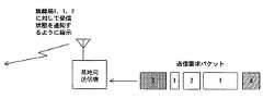
図4は、送信要求パケットが基地局に到達した順序を示す説明図である。このとき、基地局は、送信すべきパケットの送信先無線局を、先頭のパケットからいくつか選び、これら無線局に対して受信状態の報告を要求する。ここでは、送信すべきパケットの送信先無線局が3、1、2の順序で発生している。
【0023】
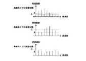
図5は、本発明による基地局から送信される参照信号の周波数−送信強度のグラフである。基地局は、受信状態の報告を求めるサブキャリア上に、間欠又は連続して参照信号を送信する。この参照信号は、送信データが変調された信号、又は既知のパターンで構成されたパイロット信号であってもよい。図5では、8つのサブキャリアの参照信号が同時に且つ等レベルで送信されている。
【0024】
下り信号は、広帯域伝送になるほど、周波数選択性によって、強く受信できる周波数帯と、そうでない周波数帯とに分かれる。この周波数選択性は、基地局と無線局との間の伝送路状態によって異なる。
【0025】
図6は、図5の参照信号を受信した3つの無線局における、参照信号の周波数−受信強度のグラフである。無線局3では3番目のサブキャリア周辺が、無線局2では5番目のサブキャリアが周辺が強く受信されている。また、無線局1では1番目及び7番目のサブキャリアが同じ程度のレベルで受信されている。
【0026】
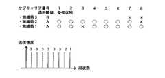
図7は、本発明の第1の実施形態における、受信状態報告信号とサブキャリアの割り当てとの説明図である。無線局は、受信状態の閾値Aに対して各サブキャリアの受信強度が上回っているか否かを基地局へ報告する。尚、閾値Aは、無線伝送が十分に品質良く行える受信強度に設定する。
【0027】
図7によれば、サブキャリアの割り当ては、送信すべき先頭のパケットの送信先無線局から順に行う。無線局3へ送信する先頭のパケットは、当該無線局3で受信強度が強いサブキャリア1〜5が割り当てられる。次に、無線局2へ送信する2番目のパケットは、まだ割り当てられていないサブキャリアのうち、当該無線局2で受信強度が強いサブキャリア6及び7が割り当てられる。最後に、無線局1へ送信する3番目のパケットは、残りのサブキャリア8の受信強度が当該無線局1で強いので、これを割り当てる。このように、3つの無線パケットが、受信状態を考慮して、先頭のパケットから順に多重化される。
【0028】
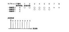
図8は、本発明の第2の実施形態における、受信状態報告信号とサブキャリアの割り当てとの説明図である。先頭のパケット送出先である無線局に対してはAより小さい閾値Bを更に設定し、閾値Bを下回るサブキャリアを基地局へ通知する。ここでの閾値Bは、受信強度が弱いことを意味する。
【0029】
図8によれば、先頭のパケットの送信先無線局3については閾値Bを用い、無線局2及び1については図7と同じ閾値Aを用いている。無線局3については、サブキャリア7及び8が閾値Bを下回っていることが分かる。従って、無線局3へ送信する先頭のパケットは、当該無線局3で受信強度が弱くないサブキャリア1〜6が割り当てられる。
【0030】
第1の実施形態では無線局3の受信状態通知には8ビット必要であったのに対し、第2の実施形態では6ビット(=サブキャリア番号3ビット×2つ)ですむので、無線局からの受信状態の報告に必要な伝送量を減らすことができる。このように第2の実施形態では、2つの閾値A及びBによって先頭の無線パケットを優先して多重化することにより先頭パケット伝送遅延を短くすることができ、十分な送信が期待できない閾値Bを下回るサブキャリアへの伝送量を減らすことができる。
【0031】
図9は、本発明の第3の実施形態における、受信状態報告信号とサブキャリアの割り当てとの説明図である。2番目以降のパケットの送出先である無線局1及び2に対して、閾値Aより大きい閾値Cを設定し、無線局1及び2では閾値Cを上回るサブキャリア番号を通知する。第1及び第2の実施形態と同様にして、受信状態表に基づいて各サブキャリアを割り当てるが、あまったサブキャリア(図9の例ではサブキャリア8)については先頭パケットのあて先である無線局3に割り当てる。
【0032】
図9によれば、2つの閾値A及びCによって先頭の無線パケットを優先して多重化することにより先頭パケット伝送遅延を短くするとともに、閾値Cが大きいために、これを上回るサブキャリア数の期待値が低く、無線局からの受信状態通知に必要な伝送量を減らす効果が期待できる。例えば、無線局2及び3の通知に要した情報量は、第3の実施形態では12ビットであるのに対し、第1の実施形態では16ビットである。
【0033】
第1から第3の実施形態では、受信状態は、1つの閾値(A、B又はC)を基準に2値状態(○又は×)で通知されているが、もちろん2値を超える複数段階の状態数で通知されてもよい。この場合、通知のための情報量が増すけれども、より効率の良いサブキャリアの割り当てが可能となる。
【0034】
割り当て結果を基地局から各無線局に通知するために、報知チャネルにて割り当て情報を通知する。報知チャネルはここで説明したサブチャネルのすべて又は一部を時分割又は符号分割で使用しても良いし、全く別のチャネルであっても良い。各無線局では、基地局からの割当情報を受信し、自局に割り当てられたサブキャリアを復調することにより所望の信号を得ることができる。
【0035】
図10は、本発明の第4の実施形態を説明するための、参照信号の2時点の周波数−受信強度のグラフである。図11は、図10の2時点にそれぞれ対応する受信状態報告信号の説明図である。ここでは、各時刻における受信状態を3段階で通知している。第4の実施形態は、受信状態の変化分のみを基地局へ通知する方法である。
【0036】
パケットのサイズによっては、複数のパケットを連続して送信する必要が生じる。また、移動中の無線局における受信状態は時々刻々と変化するため、連続して無線パケットを伝送する相手無線局からの定期的な受信状態報告が必要となる。従って、移動量の少ない移動局においては受信状態の変化も少ないので、前回の報告情報との変化分のみを通知することによって、通知のための情報量を削減することができる。
【0037】
8サブキャリアの受信状態を3段階で報告するために必要な情報量は8×log2(3)=12.7ビットとなる。これに対して受信状態の変化分を、例えば次のように符号化する。変化がない場合は「00」、+の変化がある場合は「10」、−の変化がある場合は「11」とする。このようにすると、図11の受信状態を10ビット(=(サブキャリア番号3ビット+変化分2ビット)×2つ)で伝送できることができ、通知のための情報量を削減することができる。
【0038】
また、受信状態の変化が一定レベル以下の時には、個々の受信状態を通知せずに、一括して「変化なし」と通知することも情報量を削減する上で有効である。
【0039】
ここでの受信状態の変化とは、例えば受信状態の変化量(図11の「前回との差」)の絶対値の総和を1サブキャリアで平均したものや、又は図10に示したような受信強度波形間の相関などが考えられる。
【0040】
受信状態の変化が大きい場合は、全てのサブキャリア毎の受信状態を通知する必要があり、上述の通知情報の削減方法を用いてもその効果は乏しい。この場合、受信状態の変化が一定レベル以上のとき、一括して「変化が多い」と通知することもできる。このときの各サブキャリアは、いずれも大きな時間変動を受けているので、時間平均した受信状態はどのサブキャリアでも同程度になるので、任意のサブキャリアを割り当ててよいと考えられる。尚、この方法は、継続した受信状態の報告だけではなく、1番目の受信状態報告においても適用することも好ましい。
【0041】
第1から第4の実施形態では、サブキャリア単位で受信状態の報告を行うが、これを複数のサブキャリアが含まれるサブバンド(周波数帯)の単位で行うことも好ましい。これにより、受信状態通知のための情報量が削減される。サブバンドの受信状態とは、そのサブバンドに属する1つ以上のサブキャリアの受信状態から求められる、平均的又は代表的な受信状態である。
【0042】
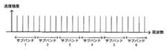
図12は、サブバンド割当方法の周波数−受信強度のグラフである。ここでは、サブキャリア数が24のときに4サブキャリア毎に1つのサブバンドを形成している。これにより、通知すべき受信状態の情報量は1/4となる。
【0043】
サブバンドの帯域幅がコヒーレンス帯域幅程度以下であれば、サブバンド単位で受信状態の報告を行っても大きな劣化はない。その場合のサブキャリアの割り当ては、サブバンド単位で一括して行っても良い。
【0044】
サブバンドの帯域幅がコヒーレンス帯域幅程度以上であれば、隣接する複数のサブバンドの受信状態から個々のサブキャリア又はコヒーレンス帯域の受信状態を補完推定し、サブキャリア又はコヒーレンス帯域の単位で無線割り当てを行ったほうが周波数効率の良い割り当てができる。
【0045】
前述した本発明のサブキャリア割当方法の実施形態によれば、受信状態報告信号とサブキャリアの割り当てとの関係も種々考えることができ、本発明の技術思想及び見地の範囲の種々の変更、修正及び省略は、当業者によれば容易に行うことができる。前述の説明はあくまで例であって、何ら制約しようとするものではない。本発明は、特許請求の範囲及びその均等物として限定するものにのみ制約される。
【0046】
【発明の効果】
以上、詳細に説明したように、本発明の無線通信システムのサブキャリア割り当て方法によれば、無線局毎に受信強度の強いサブキャリアを用いてパケットを多重化するので、全てのサブキャリアを均等に用いてパケット伝送する従来技術に比べて、周波数効率のよい下り信号伝送が達成される。
【図面の簡単な説明】
【図1】対象となる無線通信システムの構成図である。
【図2】従来技術による、送信要求があったパケットから順次送信する方法である。
【図3】従来技術による、スペクトル拡散信号を用いて伝送する場合に、複数の移動局宛にパケットを多重化して伝送する方法である。
【図4】送信要求パケットが基地局に到達した順序を示す説明図である。
【図5】本発明による、基地局から送信される参照信号の周波数−送信強度のグラフである。
【図6】図5の参照信号を受信した3つの無線局における、参照信号の周波数−受信強度のグラフである。
【図7】本発明の第1の実施形態における、受信状態報告信号とサブキャリアの割り当てとの説明図である。
【図8】本発明の第2の実施形態における、受信状態報告信号とサブキャリアの割り当てとの説明図である。
【図9】本発明の第3の実施形態における、受信状態報告信号とサブキャリアの割り当てとの説明図である。
【図10】本発明の第4の実施形態を説明するための、参照信号の2時点の周波数−受信強度のグラフである。
【図11】図10の2時点にそれぞれ対応する受信状態報告信号の説明図である。
【図12】サブバンド割当方法の周波数−受信強度のグラフである。[0001]
BACKGROUND OF THE INVENTION
The present invention relates to a subcarrier (or subband) allocation method for a wireless communication system.
[0002]
[Prior art]
FIG. 1 is a configuration diagram of a target wireless communication system. This system includes a base station and one or more radio stations that multiplex radio packets using a plurality of subcarriers and communicate with the base station. As shown in FIG. 1, a solid line with an arrow represents a downlink signal (a signal from the base station to the radio station), and a broken line with an arrow represents an uplink signal (a signal from the radio station to the base station).
[0003]
Conventionally, a multiple access method in a wireless communication system is realized by frequency division multiplexing (FDMA), time division multiplexing (TDMA), code division multiplexing (CDMA), or a combination (hybrid) thereof. A plurality of these divided elements are prepared as channels, and each is assigned to each radio station to perform simultaneous connection. That is, a plurality of radio channels identified by different frequencies, different time slots, or different spreading codes are prepared and assigned to each radio station.
[0004]
The base station prepares a carrier (carrier wave) by dividing the frequency band allocated to the base station equally in principle. For example, about 40 FDMA / TDMA carriers can be prepared from a 1 MHz band at intervals of 25 kHz, or four CDMA carriers can be prepared from a 20 MHz band at intervals of 5 MHz.
[0005]
In addition, the carrier frequency of the radio channel assigned by the base station to the radio station is not changed in principle during communication with the same base station. In other words, the specific frequency is continuously used regardless of the instantaneous fluctuation of the frequency characteristic of the propagation path caused by the movement of the radio station.
[0006]
Here, a conventional technique of wireless packet transmission using multicarrier transmission will be described.
[0007]
OFDM is a method for transmitting a signal by a plurality of subcarriers, and is scheduled to be used in digital terrestrial broadcasting or high-speed wireless LAN. In general, the subcarrier is set to a transmission rate that can be regarded as flat fading (about 10 ksps in an outdoor environment). Since all the subcarriers are used to transmit a downlink signal addressed to one user, there is a drawback that transmission efficiency deteriorates due to subcarriers with poor reception at each radio station.
[0008]
For high-speed packet transmission using MC-CDMA, characteristics evaluation etc. are currently in progress (for example, Sadayuki Abeda et al., “SC / DS-CDMA, MC / DS-CDMA, MC- in downlink broadband wireless packet transmission). CDMA characteristics comparison ”, IEICE Technical Report, RCS99-130, October 1999, etc.). Since each subcarrier is spread spectrum, its occupied band is wide and generally subjected to frequency selective fading, so that variations in the reception state of subcarriers are reduced.
[0009]
FIG. 2 shows a conventional method of sequentially transmitting packets that have been requested to be transmitted. The number written in each packet is the wireless station number of the other party that transmits the packet. The packet for the
[0010]
FIG. 3 shows a conventional method of multiplexing and transmitting packets addressed to a plurality of mobile stations when transmitting using a spread spectrum signal. Since each wireless packet is multiplexed with a different spreading code, it is not assigned according to the reception state. Further, in MC-CDMA, since the occupied band of subcarriers is set wide with the expectation of the effect of path diversity, the difference in subcarrier reception state is generally small.
[0011]
[Problems to be solved by the invention]
However, each of the conventional methods has a problem that the base station assigns even a subcarrier having a poor reception state for the radio station. In the method of FIG. 2, when a plurality of subcarriers are allocated, both the subcarriers with good reception status and the subcarriers with poor reception are allocated together, so that the transmission efficiency as a whole deteriorates. Further, in the method of FIG. 3, since the occupied band of subcarriers is wide and both a good reception part and a bad reception part are mixed, the transmission efficiency as a whole deteriorates as in FIG.
[0012]
Accordingly, an object of the present invention is to provide a subcarrier allocation method that does not allocate a subcarrier having a poor reception state for the radio station, which causes deterioration in transmission efficiency in a radio communication system.
[0013]
[Means for Solving the Problems]
Therefore, according to the subcarrier allocation method of the radio communication system of the present invention, the base station transmits a reference signal of a plurality of subcarriers at the same time and at the same level to the radio station, and the radio station transmits the reference signal. A second stage of notifying the base station of the reception status of each subcarrier, and the base station determines a subcarrier to communicate with the transmission destination radio station in the order of transmission according to the reception status of each subcarrier And a third stage. The subcarrier is preferably set to a transmission rate that can be regarded as flat fading.
[0014]
According to the first embodiment of the present invention, for the second stage, a first threshold value A of reception intensity is set, and the reception state for each subcarrier has a reception intensity equal to or higher than the first threshold value A. It is preferable to represent the binary 1 bit of the received intensity smaller than the first threshold A.
[0015]
According to the second embodiment of the present invention, for the second stage, the second threshold B having a reception strength smaller than the first threshold A is set, and the transmission destination of the packet to be transmitted first by the base station It is also preferable that the radio station notifies the base station of an identifier of a subcarrier having a reception strength smaller than the second threshold B.
[0016]
According to the third embodiment of the present invention, for the second stage, a third threshold C having a reception strength greater than the first threshold A is set, and the base station It is also preferable that the transmission destination radio station notifies the base station of an identifier of a subcarrier having a reception strength larger than the third threshold value C.
[0017]
According to the fourth embodiment of the present invention, with respect to the second stage, the reception state is represented by information amounts of a plurality of stages, and only the change from the previous reception state for each subcarrier is notified to the base station. It is also preferable to do. If the change in the reception state is expressed by several binary bits, and the change in the reception state is equal to or higher than a certain level, the change in the reception state for each subcarrier is not notified and “changes are large” at once. It is also preferable to notify the base station of such information. Thereby, the amount of information to be notified can be reduced.
[0018]
According to another embodiment of the present invention, the subcarrier is preferably a subband including a plurality of subcarriers. Thereby, the amount of information to be notified can be reduced.
[0019]
DETAILED DESCRIPTION OF THE INVENTION
Hereinafter, embodiments of the present invention will be described in detail with reference to the drawings.
[0020]
The present invention assigns subcarriers in a base station based on a reception status report from a radio station and transmission traffic to each radio station. In the following description, each subcarrier is described as being assigned to only one radio station. However, if the subcarrier is spread spectrum, it is possible to assign one subcarrier to a plurality of radio stations.
[0021]
However, when the occupied bandwidth of each subcarrier has frequency selectivity, it is preferable to narrow the occupied bandwidth of the subcarrier to such an extent that the frequency selectivity can be ignored. That is, the occupied bandwidth of the subcarrier is set to be less than or equal to the coherence bandwidth.
[0022]
FIG. 4 is an explanatory diagram showing the order in which the transmission request packets arrive at the base station. At this time, the base station selects several transmission destination wireless stations of the packet to be transmitted from the top packet, and requests the wireless station to report the reception state. Here, the transmission destination radio stations of the packets to be transmitted are generated in the order of 3, 1, and 2.
[0023]
FIG. 5 is a frequency-transmission strength graph of a reference signal transmitted from a base station according to the present invention. The base station transmits a reference signal intermittently or continuously on a subcarrier for which a reception status report is requested. The reference signal may be a signal in which transmission data is modulated or a pilot signal configured with a known pattern. In FIG. 5, eight subcarrier reference signals are transmitted simultaneously and at the same level.
[0024]
The downlink signal is divided into a frequency band that can be received strongly and a frequency band that is not so strong depending on the frequency selectivity as the transmission becomes wider. This frequency selectivity varies depending on the transmission path state between the base station and the radio station.
[0025]
FIG. 6 is a graph of reference signal frequency-reception strength at three wireless stations that have received the reference signal of FIG. In the
[0026]
FIG. 7 is an explanatory diagram of a reception status report signal and subcarrier allocation in the first embodiment of the present invention. The radio station reports to the base station whether or not the reception intensity of each subcarrier exceeds the reception state threshold A. The threshold A is set to a reception intensity at which wireless transmission can be performed with sufficient quality.
[0027]
According to FIG. 7, the allocation of subcarriers is performed in order from the transmission destination radio station of the first packet to be transmitted. The first packet to be transmitted to the
[0028]
FIG. 8 is an explanatory diagram of a reception status report signal and subcarrier allocation in the second embodiment of the present invention. A threshold B smaller than A is further set for the wireless station that is the first packet transmission destination, and the subcarriers below the threshold B are notified to the base station. The threshold value B here means that the reception intensity is weak.
[0029]
According to FIG. 8, the threshold value B is used for the
[0030]
In the first embodiment, 8 bits are required for notification of the reception status of the
[0031]
FIG. 9 is an explanatory diagram of a reception status report signal and subcarrier allocation in the third embodiment of the present invention. A threshold C larger than the threshold A is set for the
[0032]
According to FIG. 9, the leading packet transmission delay is shortened by multiplexing the leading wireless packet with two thresholds A and C, and the threshold C is large. The value is low, and the effect of reducing the amount of transmission required for the reception status notification from the radio station can be expected. For example, the amount of information required for notification of the
[0033]
In the first to third embodiments, the reception state is notified in a binary state (O or X) based on one threshold value (A, B or C). You may be notified by the number of states. In this case, although the amount of information for notification increases, subcarrier allocation can be performed more efficiently.
[0034]
In order to notify the allocation result from the base station to each wireless station, the allocation information is notified through the broadcast channel. The broadcast channel may use all or part of the subchannels described here in time division or code division, or may be a completely different channel. Each radio station can obtain the desired signal by receiving the allocation information from the base station and demodulating the subcarriers allocated to the own station.
[0035]
FIG. 10 is a graph of frequency-reception strength at two time points of the reference signal for explaining the fourth embodiment of the present invention. FIG. 11 is an explanatory diagram of reception status report signals respectively corresponding to the two time points in FIG. Here, the reception state at each time is notified in three stages. The fourth embodiment is a method of notifying the base station of only the change in the reception state.
[0036]
Depending on the size of the packet, a plurality of packets need to be transmitted continuously. In addition, since the reception state of a moving wireless station changes from moment to moment, periodic reception state reporting from a counterpart wireless station that continuously transmits wireless packets is required. Accordingly, since the change in the reception state is small in a mobile station with a small amount of movement, the amount of information for notification can be reduced by notifying only the change from the previous report information.
[0037]
The amount of information necessary to report the reception status of 8 subcarriers in 3 stages is 8 × log2 (3) = 12.7 bits. On the other hand, the change in the reception state is encoded as follows, for example. If there is no change, “00” is set, “+” is set “10”, and − is set “11”. In this way, the reception state of FIG. 11 can be transmitted with 10 bits (= (
[0038]
It is also effective in reducing the amount of information to collectively notify “no change” without notifying each reception state when the change in reception state is below a certain level.
[0039]
The change in the reception state here is, for example, an average of the sum of absolute values of the amount of change in the reception state ("difference from the previous time" in FIG. 11) with one subcarrier, or as shown in FIG. Correlation between received intensity waveforms can be considered.
[0040]
When the change in the reception state is large, it is necessary to notify the reception state for every subcarrier, and even if the above-described notification information reduction method is used, the effect is poor. In this case, when the change in the reception state is equal to or higher than a certain level, it can be notified collectively that “there is a lot of change”. Since each subcarrier at this time has undergone large time fluctuations, the time-averaged reception state is almost the same in any subcarrier, so it is considered that any subcarrier may be allocated. This method is preferably applied not only to the continuous reception status report but also to the first reception status report.
[0041]
In the first to fourth embodiments, the reception state is reported in units of subcarriers, but it is also preferable to perform this in units of subbands (frequency bands) including a plurality of subcarriers. Thereby, the amount of information for notification of reception status is reduced. The subband reception state is an average or representative reception state obtained from the reception state of one or more subcarriers belonging to the subband.
[0042]
FIG. 12 is a graph of frequency-reception strength in the subband allocation method. Here, when the number of subcarriers is 24, one subband is formed for every 4 subcarriers. Thereby, the information amount of the reception state to be notified becomes 1/4.
[0043]
If the subband bandwidth is less than or equal to the coherence bandwidth, there is no significant degradation even if the reception state is reported in subband units. In this case, subcarrier allocation may be performed collectively in units of subbands.
[0044]
If the subband bandwidth is equal to or greater than the coherence bandwidth, the reception state of each subcarrier or coherence band is complementarily estimated from the reception state of a plurality of adjacent subbands, and radio allocation is performed in units of subcarriers or coherence bands. The allocation with better frequency efficiency can be performed.
[0045]
According to the embodiment of the subcarrier allocation method of the present invention described above, various relationships between the reception status report signal and the subcarrier allocation can be considered, and various changes and modifications of the technical idea and scope of the present invention can be considered. The omission can be easily performed by those skilled in the art. The above description is merely an example, and is not intended to be restrictive. The invention is limited only as defined in the following claims and the equivalents thereto.
[0046]
【The invention's effect】
As described above in detail, according to the subcarrier allocation method of the radio communication system of the present invention, packets are multiplexed using subcarriers with strong reception strength for each radio station, so all subcarriers are equalized. Compared with the prior art in which packet transmission is used for the transmission, downlink signal transmission with higher frequency efficiency is achieved.
[Brief description of the drawings]
FIG. 1 is a configuration diagram of a target wireless communication system.
FIG. 2 is a method of transmitting sequentially from packets for which a transmission request has been made according to the prior art.
FIG. 3 shows a conventional method for multiplexing and transmitting packets addressed to a plurality of mobile stations when transmitting using a spread spectrum signal.
FIG. 4 is an explanatory diagram showing an order in which transmission request packets arrive at a base station.
FIG. 5 is a frequency-transmission strength graph of a reference signal transmitted from a base station according to the present invention.
6 is a graph of frequency vs. reception intensity of a reference signal in three wireless stations that have received the reference signal of FIG.
FIG. 7 is an explanatory diagram of a reception state report signal and subcarrier allocation in the first embodiment of the present invention.
FIG. 8 is an explanatory diagram of a reception state report signal and subcarrier allocation in the second embodiment of the present invention.
FIG. 9 is an explanatory diagram of a reception state report signal and subcarrier allocation in the third embodiment of the present invention.
FIG. 10 is a graph of frequency vs. reception intensity at two time points of a reference signal for explaining a fourth embodiment of the present invention.
11 is an explanatory diagram of reception status report signals respectively corresponding to two time points in FIG.
FIG. 12 is a graph of frequency-reception strength in a subband allocation method.
Claims (7)
Translated fromJapanese前記基地局が、同時に且つ等レベルの複数のサブキャリアの参照信号を、前記無線局へ送信する第1の段階と、
受信強度の第1の閾値A及び前記第1の閾値Aよりも小さい受信強度の第2の閾値Bを設定し、サブキャリア毎の受信状態について、前記基地局が最初に送信すべきパケットの送信先無線局は該第2の閾値Bよりも小さい受信強度のサブキャリアの識別子を該基地局へ通知し、前記基地局が2番目以降に送信すべきパケットの送信先無線局は、前記第1の閾値A以上の受信強度のサブキャリアの識別子を前記基地局へ通知する第2の段階と、
前記基地局が、前記サブキャリア毎の受信状態に応じて、送信順にパケットの送信先無線局と通信を行うサブキャリアを決定する第3の段階と
を有することを特徴とする無線通信システムのサブキャリア割当方法。In a subcarrier allocation method of a radio communication system having a base station and one or more radio stations that multiplex radio packets using a plurality of subcarriers and communicate with the base station,
A first stage in which the base station transmits reference signals of a plurality of subcarriers at the same level and at the same level to the radio station;
A first threshold A of reception strength and a second threshold B of reception strength smaller than the first threshold A are set, and transmission of a packet to be transmitted first by the base station with respect to the reception state for each subcarrier The destination radio station notifies the base station of an identifier of a subcarrier having a reception strength smaller than the second threshold B, and the destination radio station of the packet to be transmitted by the base station after the second is the first radio station. A second step of notifying the base station ofan identifier of a subcarrier having a reception strength equal to or greater than a threshold A of
A sub-stage of a radio communication system, wherein the base station has a third step of determining sub-carriers to communicate with a packet-destination radio station in the order of transmission according to a reception state of each sub-carrier. Carrier allocation method.
前記基地局が、同時に且つ等レベルの複数のサブキャリアの参照信号を、前記無線局へ送信する第1の段階と、
前記受信強度の第1の閾値A及び該第1の閾値Aよりも大きい受信強度の第3の閾値Cを設定し、サブキャリア毎の受信状態について、前記基地局が最初に送信すべきパケットの送信先無線局は前記第1の閾値A以上の受信強度のサブキャリアの識別子を前記基地局へ通知し、前記基地局が2番目以降に送信すべきパケットの送信先無線局は該第3の閾値Cよりも大きい受信強度のサブキャリアの識別子を前記基地局へ通知する第2の段階と、
前記基地局が、前記サブキャリア毎の受信状態に応じて、送信順にパケットの送信先無線局と通信を行うサブキャリアを決定する第3の段階と
を有することを特徴とする無線通信システムのサブキャリア割当方法。In a subcarrier allocation method of a radio communication system having a base station and one or more radio stations that multiplex radio packets using a plurality of subcarriers and communicate with the base station,
A first stage in which the base station transmits reference signals of a plurality of subcarriers at the same level and at the same level to the radio station;
The first threshold value A of the reception strength and the third threshold value C of the reception strength larger than the first threshold value A are set, and the reception status of each subcarrier of the packet to be transmitted first by the base station is set. The transmission destination radio station notifies the base station of a subcarrier identifier having a reception strength equal to or higher than the first threshold value A, and the transmission destination radio station of the packet to be transmitted by the base station after the second is the third A second step of notifying the base station ofan identifier of a subcarrier having a reception strength greater than a threshold C ;
A sub-stage of a radio communication system, wherein the base station has a third step of determining sub-carriers to communicate with a packet-destination radio station in the order of transmission according to a reception state of each sub-carrier. Carrier allocation method.
Priority Applications (2)
| Application Number | Priority Date | Filing Date | Title |
|---|---|---|---|
| JP2000049344AJP3826653B2 (en) | 2000-02-25 | 2000-02-25 | Subcarrier allocation method for wireless communication system |
| US09/790,499US6836484B2 (en) | 2000-02-25 | 2001-02-23 | Wireless packet communication method and system for transmitting packets between base station and radio terminal station |
Applications Claiming Priority (1)
| Application Number | Priority Date | Filing Date | Title |
|---|---|---|---|
| JP2000049344AJP3826653B2 (en) | 2000-02-25 | 2000-02-25 | Subcarrier allocation method for wireless communication system |
Publications (2)
| Publication Number | Publication Date |
|---|---|
| JP2001238269A JP2001238269A (en) | 2001-08-31 |
| JP3826653B2true JP3826653B2 (en) | 2006-09-27 |
Family
ID=18571300
Family Applications (1)
| Application Number | Title | Priority Date | Filing Date |
|---|---|---|---|
| JP2000049344AExpired - LifetimeJP3826653B2 (en) | 2000-02-25 | 2000-02-25 | Subcarrier allocation method for wireless communication system |
Country Status (2)
| Country | Link |
|---|---|
| US (1) | US6836484B2 (en) |
| JP (1) | JP3826653B2 (en) |
Families Citing this family (154)
| Publication number | Priority date | Publication date | Assignee | Title |
|---|---|---|---|---|
| US9130810B2 (en) | 2000-09-13 | 2015-09-08 | Qualcomm Incorporated | OFDM communications methods and apparatus |
| US7295509B2 (en) | 2000-09-13 | 2007-11-13 | Qualcomm, Incorporated | Signaling method in an OFDM multiple access system |
| US6947748B2 (en) | 2000-12-15 | 2005-09-20 | Adaptix, Inc. | OFDMA with adaptive subcarrier-cluster configuration and selective loading |
| JP4171261B2 (en) | 2001-08-27 | 2008-10-22 | 松下電器産業株式会社 | Wireless communication apparatus and wireless communication method |
| US7170873B1 (en)* | 2001-08-30 | 2007-01-30 | Cisco Technology, Inc. | Method to decouple assess point association from directional antennas |
| JP3665598B2 (en) | 2001-09-26 | 2005-06-29 | 株式会社東芝 | Multi-carrier communication device |
| US6898418B2 (en)* | 2001-11-02 | 2005-05-24 | Texas Instruments Incorporated | Method of and apparatus for implementing adaptive downstream modulation in a fixed wireless communication system |
| JP3637965B2 (en)* | 2001-11-22 | 2005-04-13 | 日本電気株式会社 | Wireless communication system |
| US6975650B2 (en) | 2002-02-13 | 2005-12-13 | Interdigital Technology Corporation | Transport block set segmentation |
| US7289509B2 (en)* | 2002-02-14 | 2007-10-30 | International Business Machines Corporation | Apparatus and method of splitting a data stream over multiple transport control protocol/internet protocol (TCP/IP) connections |
| JP3898533B2 (en) | 2002-03-11 | 2007-03-28 | シャープ株式会社 | Wireless communication system |
| CN102769596B (en)* | 2002-07-16 | 2017-12-08 | 光学无线技术有限责任公司 | Sending method and dispensing device and method of reseptance and reception device |
| JP4043322B2 (en)* | 2002-09-06 | 2008-02-06 | 三菱電機株式会社 | Retransmission control method and communication apparatus |
| JP4115784B2 (en)* | 2002-09-11 | 2008-07-09 | 三菱電機株式会社 | Retransmission control method and communication apparatus |
| JP4289854B2 (en)* | 2002-09-20 | 2009-07-01 | 京セラ株式会社 | Radio base apparatus, mobile terminal apparatus, reference signal control method, and reference signal control program |
| JP3732830B2 (en) | 2002-10-10 | 2006-01-11 | 松下電器産業株式会社 | Multicarrier transmission apparatus and multicarrier transmission method |
| KR100507519B1 (en) | 2002-12-13 | 2005-08-17 | 한국전자통신연구원 | Method and Apparatus for Signal Constitution for Downlink of OFDMA Based Cellular Systems |
| JP4163941B2 (en)* | 2002-12-24 | 2008-10-08 | 松下電器産業株式会社 | Wireless transmission apparatus and wireless transmission method |
| JP4256158B2 (en) | 2002-12-26 | 2009-04-22 | パナソニック株式会社 | Wireless communication apparatus and wireless communication method |
| JP2004266338A (en)* | 2003-01-31 | 2004-09-24 | Matsushita Electric Ind Co Ltd | Multi-carrier transmitting device, multi-carrier receiving device, and multi-carrier wireless communication method |
| US8081598B2 (en) | 2003-02-18 | 2011-12-20 | Qualcomm Incorporated | Outer-loop power control for wireless communication systems |
| US8391249B2 (en) | 2003-02-18 | 2013-03-05 | Qualcomm Incorporated | Code division multiplexing commands on a code division multiplexed channel |
| US8150407B2 (en) | 2003-02-18 | 2012-04-03 | Qualcomm Incorporated | System and method for scheduling transmissions in a wireless communication system |
| US7155236B2 (en) | 2003-02-18 | 2006-12-26 | Qualcomm Incorporated | Scheduled and autonomous transmission and acknowledgement |
| US8023950B2 (en) | 2003-02-18 | 2011-09-20 | Qualcomm Incorporated | Systems and methods for using selectable frame durations in a wireless communication system |
| US7660282B2 (en) | 2003-02-18 | 2010-02-09 | Qualcomm Incorporated | Congestion control in a wireless data network |
| US20040160922A1 (en) | 2003-02-18 | 2004-08-19 | Sanjiv Nanda | Method and apparatus for controlling data rate of a reverse link in a communication system |
| US7215930B2 (en) | 2003-03-06 | 2007-05-08 | Qualcomm, Incorporated | Method and apparatus for providing uplink signal-to-noise ratio (SNR) estimation in a wireless communication |
| US8705588B2 (en) | 2003-03-06 | 2014-04-22 | Qualcomm Incorporated | Systems and methods for using code space in spread-spectrum communications |
| JP4139257B2 (en)* | 2003-04-01 | 2008-08-27 | 日本電信電話株式会社 | Wireless packet communication method and wireless packet communication device |
| US7012912B2 (en)* | 2003-05-14 | 2006-03-14 | Qualcomm Incorporated | Power control and scheduling in an OFDM system |
| US8477592B2 (en) | 2003-05-14 | 2013-07-02 | Qualcomm Incorporated | Interference and noise estimation in an OFDM system |
| KR100689382B1 (en) | 2003-06-20 | 2007-03-02 | 삼성전자주식회사 | Transmission apparatus and method in mobile communication system based on orthogonal multiplexing |
| JP4482293B2 (en) | 2003-07-03 | 2010-06-16 | パナソニック株式会社 | Base station apparatus and transmission method |
| US8489949B2 (en) | 2003-08-05 | 2013-07-16 | Qualcomm Incorporated | Combining grant, acknowledgement, and rate control commands |
| JP4734116B2 (en) | 2003-08-06 | 2011-07-27 | パナソニック株式会社 | Wireless communication apparatus and reception quality reporting method |
| BRPI0413705B1 (en)* | 2003-08-20 | 2020-12-01 | Godo Kaisha Ip Bridge 1 | wireless communication device and subcarrier allocation method |
| CN102932125B (en) | 2003-08-20 | 2016-01-13 | 松下电器(美国)知识产权公司 | Base station apparatus and the method for reseptance for base station apparatus |
| KR100539925B1 (en) | 2003-08-22 | 2005-12-28 | 삼성전자주식회사 | Apparatus and method for sub-carrier alocation in ofdm system |
| DE60315301T2 (en)* | 2003-10-21 | 2009-04-09 | Alcatel Lucent | Method for assigning the subcarriers and for selecting the modulation scheme in a wireless multicarrier transmission system |
| KR100557158B1 (en) | 2003-11-12 | 2006-03-03 | 삼성전자주식회사 | Apparatus and Method for Subcarrier Allocation in Mobile Communication System Using Orthogonal Frequency Division Multiplexing |
| JP4418377B2 (en)* | 2004-01-29 | 2010-02-17 | パナソニック株式会社 | Communication terminal device and base station device |
| KR100651454B1 (en) | 2004-03-05 | 2006-11-29 | 삼성전자주식회사 | Subchannel Allocation Method in Orthogonal Frequency Division Multiple Access Cellular Communication Systems |
| MXPA06010110A (en)* | 2004-03-05 | 2007-03-07 | Nextnet Wireless Inc | System and method for adaptive modulation. |
| KR100713528B1 (en)* | 2004-03-12 | 2007-05-02 | 삼성전자주식회사 | Apparatus and method for transmitting sub-channel signal in a communication system using orthogonal frequency division multiple access scheme |
| EP1762044A1 (en)* | 2004-06-24 | 2007-03-14 | Philips Intellectual Property & Standards GmbH | A method for signaling thestatus of a subcarrier in a mc network and a method for adaptively allocating the subcarriers in a mc network |
| JP4640787B2 (en)* | 2004-06-28 | 2011-03-02 | 株式会社エヌ・ティ・ティ・ドコモ | Transmitting station, mobile communication system, and radio resource allocation method |
| JP4955080B2 (en)* | 2004-06-28 | 2012-06-20 | 株式会社エヌ・ティ・ティ・ドコモ | Reception station, transmission station, mobile communication system, and frequency block allocation method |
| KR100640474B1 (en)* | 2004-07-10 | 2006-10-30 | 삼성전자주식회사 | Downlink Resource Allocation Method for Multi-carrier-based Code Division Multiple Access Systems |
| US9137822B2 (en) | 2004-07-21 | 2015-09-15 | Qualcomm Incorporated | Efficient signaling over access channel |
| US9148256B2 (en) | 2004-07-21 | 2015-09-29 | Qualcomm Incorporated | Performance based rank prediction for MIMO design |
| WO2006028204A1 (en)* | 2004-09-10 | 2006-03-16 | Matsushita Electric Industrial Co., Ltd. | Wireless communication apparatus and wireless communication method |
| JP4647612B2 (en)* | 2004-09-17 | 2011-03-09 | パナソニック株式会社 | Transmission control frame generation device and transmission control device |
| US8018930B2 (en) | 2004-10-01 | 2011-09-13 | Qualcomm Incorporated | Apparatus and method for receiving packet data on a subset of carrier frequencies in a wireless communication system |
| EP2683108B1 (en) | 2004-10-29 | 2018-03-14 | Fujitsu Limited | Communications apparatus and communications system using multicarrier transmission mode |
| CN102098261B (en)* | 2004-10-29 | 2016-04-20 | 富士通株式会社 | Based on communicator and the communication system of multicarrier transmission mode |
| US7822132B2 (en) | 2004-11-02 | 2010-10-26 | Nec Corporation | OFDM communication system |
| JP4684628B2 (en)* | 2004-11-16 | 2011-05-18 | Kddi株式会社 | Subcarrier allocation apparatus and multicarrier radio communication system |
| CN1780278A (en)* | 2004-11-19 | 2006-05-31 | 松下电器产业株式会社 | Adaptive modulation and coding method and device in sub-carrier communication system |
| JP4457867B2 (en) | 2004-11-25 | 2010-04-28 | 富士通株式会社 | Wireless communication device, mobile station |
| JP4598003B2 (en)* | 2004-11-30 | 2010-12-15 | パナソニック株式会社 | Transmission control frame generation device, transmission control frame processing device, transmission control frame generation method, and transmission control frame processing method |
| JP4526944B2 (en)* | 2004-12-28 | 2010-08-18 | パナソニック株式会社 | Multi-antenna communication apparatus and multiplexing method determination method |
| JP4809245B2 (en)* | 2004-12-28 | 2011-11-09 | 株式会社日立製作所 | Communication control method, wireless communication system, and wireless communication device |
| KR100981514B1 (en) | 2004-12-30 | 2010-09-10 | 삼성전자주식회사 | Adaptive Subchannel and Bit Allocation Method Using Partial Channel Information Feedback in Orthogonal Frequency Division Multiple Access Communication Systems |
| US20090279420A1 (en)* | 2005-01-11 | 2009-11-12 | Nec Corporation | Base station apparatus, radio transmission system, radio base station program, and timing estimation method |
| EP1838020A4 (en)* | 2005-01-14 | 2013-01-16 | Fujitsu Ltd | FREQUENCY DIVISION COMMUNICATION SYSTEM |
| JP4632245B2 (en)* | 2005-02-23 | 2011-02-16 | 株式会社エヌ・ティ・ティ・ドコモ | Transmitting station, mobile communication system, and transmission power control method |
| US8306131B2 (en) | 2005-02-25 | 2012-11-06 | Kyocera Corporation | Communications systems |
| KR100931410B1 (en)* | 2005-02-25 | 2009-12-10 | 교세라 가부시키가이샤 | Communication systems |
| JPWO2006092856A1 (en)* | 2005-03-02 | 2008-08-07 | 富士通株式会社 | Multi-carrier communication method and base station and mobile station used therefor |
| US9246560B2 (en) | 2005-03-10 | 2016-01-26 | Qualcomm Incorporated | Systems and methods for beamforming and rate control in a multi-input multi-output communication systems |
| US9154211B2 (en) | 2005-03-11 | 2015-10-06 | Qualcomm Incorporated | Systems and methods for beamforming feedback in multi antenna communication systems |
| US8446892B2 (en) | 2005-03-16 | 2013-05-21 | Qualcomm Incorporated | Channel structures for a quasi-orthogonal multiple-access communication system |
| US9143305B2 (en) | 2005-03-17 | 2015-09-22 | Qualcomm Incorporated | Pilot signal transmission for an orthogonal frequency division wireless communication system |
| US9520972B2 (en) | 2005-03-17 | 2016-12-13 | Qualcomm Incorporated | Pilot signal transmission for an orthogonal frequency division wireless communication system |
| US9461859B2 (en) | 2005-03-17 | 2016-10-04 | Qualcomm Incorporated | Pilot signal transmission for an orthogonal frequency division wireless communication system |
| US9184870B2 (en) | 2005-04-01 | 2015-11-10 | Qualcomm Incorporated | Systems and methods for control channel signaling |
| JP4960230B2 (en)* | 2005-04-08 | 2012-06-27 | シャープ株式会社 | Radio transmitter and radio communication system |
| US9036538B2 (en) | 2005-04-19 | 2015-05-19 | Qualcomm Incorporated | Frequency hopping design for single carrier FDMA systems |
| US9408220B2 (en) | 2005-04-19 | 2016-08-02 | Qualcomm Incorporated | Channel quality reporting for adaptive sectorization |
| US8611284B2 (en) | 2005-05-31 | 2013-12-17 | Qualcomm Incorporated | Use of supplemental assignments to decrement resources |
| US8879511B2 (en) | 2005-10-27 | 2014-11-04 | Qualcomm Incorporated | Assignment acknowledgement for a wireless communication system |
| US8565194B2 (en) | 2005-10-27 | 2013-10-22 | Qualcomm Incorporated | Puncturing signaling channel for a wireless communication system |
| US8462859B2 (en) | 2005-06-01 | 2013-06-11 | Qualcomm Incorporated | Sphere decoding apparatus |
| JP4834352B2 (en) | 2005-06-14 | 2011-12-14 | 株式会社エヌ・ティ・ティ・ドコモ | Base station, mobile station, and power control method |
| US9179319B2 (en) | 2005-06-16 | 2015-11-03 | Qualcomm Incorporated | Adaptive sectorization in cellular systems |
| US8599945B2 (en) | 2005-06-16 | 2013-12-03 | Qualcomm Incorporated | Robust rank prediction for a MIMO system |
| EP1900167B1 (en)* | 2005-06-28 | 2016-08-17 | Koninklijke Philips N.V. | A handshaking method and apparatus for ofdm systems with unknown sub-channel availability |
| US8139662B2 (en)* | 2005-08-04 | 2012-03-20 | Panasonic Corporation | Mobile station device |
| US8885628B2 (en) | 2005-08-08 | 2014-11-11 | Qualcomm Incorporated | Code division multiplexing in a single-carrier frequency division multiple access system |
| CA2618616C (en)* | 2005-08-19 | 2016-02-16 | Matsushita Electric Industrial Co. Ltd. | Wireless communication mobile station device, wireless communication base station device and cqi report method |
| US9209956B2 (en) | 2005-08-22 | 2015-12-08 | Qualcomm Incorporated | Segment sensitive scheduling |
| US20070041457A1 (en) | 2005-08-22 | 2007-02-22 | Tamer Kadous | Method and apparatus for providing antenna diversity in a wireless communication system |
| US8644292B2 (en) | 2005-08-24 | 2014-02-04 | Qualcomm Incorporated | Varied transmission time intervals for wireless communication system |
| US9136974B2 (en) | 2005-08-30 | 2015-09-15 | Qualcomm Incorporated | Precoding and SDMA support |
| JP5063883B2 (en)* | 2005-09-29 | 2012-10-31 | 富士通株式会社 | Wireless communication apparatus, transmission method, transmission apparatus, data transmission system, and data transmission method |
| WO2007043097A1 (en) | 2005-09-30 | 2007-04-19 | National Institute Of Information And Communications Technology, Incorporated Administrative Agency | Transmitting apparatus, receiving apparatus, transmitting method, receiving method, information recording medium and program |
| US8582509B2 (en) | 2005-10-27 | 2013-11-12 | Qualcomm Incorporated | Scalable frequency band operation in wireless communication systems |
| US8693405B2 (en) | 2005-10-27 | 2014-04-08 | Qualcomm Incorporated | SDMA resource management |
| US9210651B2 (en) | 2005-10-27 | 2015-12-08 | Qualcomm Incorporated | Method and apparatus for bootstraping information in a communication system |
| US8477684B2 (en) | 2005-10-27 | 2013-07-02 | Qualcomm Incorporated | Acknowledgement of control messages in a wireless communication system |
| US9088384B2 (en) | 2005-10-27 | 2015-07-21 | Qualcomm Incorporated | Pilot symbol transmission in wireless communication systems |
| US9225416B2 (en) | 2005-10-27 | 2015-12-29 | Qualcomm Incorporated | Varied signaling channels for a reverse link in a wireless communication system |
| US9144060B2 (en) | 2005-10-27 | 2015-09-22 | Qualcomm Incorporated | Resource allocation for shared signaling channels |
| US8045512B2 (en) | 2005-10-27 | 2011-10-25 | Qualcomm Incorporated | Scalable frequency band operation in wireless communication systems |
| US9172453B2 (en) | 2005-10-27 | 2015-10-27 | Qualcomm Incorporated | Method and apparatus for pre-coding frequency division duplexing system |
| US9225488B2 (en) | 2005-10-27 | 2015-12-29 | Qualcomm Incorporated | Shared signaling channel |
| WO2007052397A1 (en)* | 2005-10-31 | 2007-05-10 | Nec Corporation | Transmitting/receiving system, transmitting apparatus, and pilot signal multiplexing method used in them |
| US8054894B2 (en)* | 2005-10-31 | 2011-11-08 | Motorola Mobility, Inc. | Method and apparatus for providing channel quality feedback in an orthogonal frequency division multiplexing communication system |
| EP1950897A4 (en)* | 2005-11-02 | 2013-05-15 | Sharp Kk | Reception status information notifying method and reception status information notifying apparatus |
| US8582548B2 (en) | 2005-11-18 | 2013-11-12 | Qualcomm Incorporated | Frequency division multiple access schemes for wireless communication |
| US7764647B2 (en) | 2005-12-20 | 2010-07-27 | Sharp Kabushiki Kaisha | Communications system, and base station and terminals used therein |
| EP1968222B1 (en) | 2005-12-28 | 2016-04-06 | Fujitsu Limited | Receiver apparatus and communication system |
| US8831607B2 (en) | 2006-01-05 | 2014-09-09 | Qualcomm Incorporated | Reverse link other sector communication |
| AU2007200145A1 (en) | 2006-01-18 | 2007-08-02 | Nec Australia Pty Ltd | Method of physical resource management in a wideband communication system |
| US8249044B2 (en) | 2006-03-06 | 2012-08-21 | Sharp Kabushiki Kaisha | Notification information generating apparatus, communication apparatus, notification information generating method and program |
| US7720038B2 (en)* | 2006-03-22 | 2010-05-18 | Broadcom Corporation | Cell network selectively applying proxy mode to minimize power |
| JP4641973B2 (en)* | 2006-05-10 | 2011-03-02 | 富士通株式会社 | One-way communication method, mobile station apparatus and radio base station apparatus |
| US8208566B2 (en) | 2006-08-21 | 2012-06-26 | Samsung Electronics Co., Ltd. | Apparatus and method for transmitting/receiving feedback information in a multi-user MIMO system, and system thereof |
| US8184609B2 (en)* | 2006-08-25 | 2012-05-22 | Samsung Electronics Co., Ltd. | System and method for random access in a wireless communication system |
| WO2008041632A1 (en)* | 2006-10-04 | 2008-04-10 | Sharp Kabushiki Kaisha | Report information generation device, communication device, communication information generation method, and communication information generation program |
| WO2008041752A1 (en)* | 2006-10-05 | 2008-04-10 | Sharp Kabushiki Kaisha | Radio communication device, radio communication system, radio communication method, report information transmission method, and scheduling method |
| JP2008166936A (en) | 2006-12-27 | 2008-07-17 | Sanyo Electric Co Ltd | Allocation method, and base station apparatus using it |
| CN102355719B (en)* | 2006-12-28 | 2015-09-02 | 夏普株式会社 | Base station apparatus, dispensing device, wireless communications method and system, processor |
| WO2008084780A1 (en)* | 2007-01-09 | 2008-07-17 | Sharp Kabushiki Kaisha | Radio communication device and multichannel communication system |
| JP4906875B2 (en)* | 2007-02-15 | 2012-03-28 | 三菱電機株式会社 | Communication apparatus and transmission control method |
| JP5028618B2 (en)* | 2007-02-28 | 2012-09-19 | 国立大学法人大阪大学 | Transmission method, transmission system, and receiving apparatus |
| EP2103017B1 (en) | 2007-03-29 | 2014-01-08 | LG Electronics Inc. | Method of transmitting sounding reference signal in wireless communication system |
| CN101682490A (en)* | 2007-04-05 | 2010-03-24 | 夏普株式会社 | Communication method decision device, transmission device, reception device, OFDM adaptive modulation system, and communication method decision method |
| CA2695500A1 (en)* | 2007-08-07 | 2009-02-12 | Sharp Kabushiki Kaisha | Communication device and reception quality information generation method |
| JP5320293B2 (en)* | 2007-08-07 | 2013-10-23 | シャープ株式会社 | Base station apparatus, terminal apparatus and communication system |
| EP2180629B1 (en) | 2007-08-14 | 2017-11-29 | LG Electronics Inc. | Method for acquiring resource region information for PHICH and method of receiving PDCCH |
| KR101507785B1 (en) | 2007-08-16 | 2015-04-03 | 엘지전자 주식회사 | A method for transmitting channel quality information in a MIMO (Multiple Input Multiple Output) system |
| KR101405974B1 (en) | 2007-08-16 | 2014-06-27 | 엘지전자 주식회사 | Methods for transmitting codewords in multiple input multiple output system |
| CN102685057B (en) | 2007-09-12 | 2015-06-17 | 夏普株式会社 | Transmission apparatus and method, processor, OFDM transmission apparatus and method, and wireless communication system |
| WO2009054264A1 (en)* | 2007-10-25 | 2009-04-30 | Sharp Kabushiki Kaisha | Communication device, multicarrier communication system, and communication method |
| US7933350B2 (en)* | 2007-10-30 | 2011-04-26 | Telefonaktiebolaget Lm Ericsson (Publ) | Channel-dependent frequency-domain scheduling in an orthogonal frequency division multiplexing communications system |
| JP2008118687A (en)* | 2007-12-03 | 2008-05-22 | Sumitomo Electric Ind Ltd | Transmission equipment |
| JP4734314B2 (en)* | 2007-12-10 | 2011-07-27 | パナソニック株式会社 | Wireless communication apparatus and wireless communication method |
| US20090170500A1 (en)* | 2007-12-26 | 2009-07-02 | Kabushiki Kaisha Toshiba | Radio apparatus and radio communication method |
| JP2008104243A (en)* | 2008-01-18 | 2008-05-01 | Mitsubishi Electric Corp | Communication method |
| JP5392667B2 (en)* | 2008-03-05 | 2014-01-22 | シャープ株式会社 | COMMUNICATION SYSTEM, TRANSMISSION DEVICE, RECEPTION DEVICE, AND COMMUNICATION METHOD |
| KR101356840B1 (en) | 2008-03-19 | 2014-01-28 | 닛본 덴끼 가부시끼가이샤 | Wireless communication system, wireless communication setting method, base station, mobile station, and program |
| JP4902592B2 (en)* | 2008-05-09 | 2012-03-21 | 三菱電機株式会社 | Wireless communication system |
| KR101452504B1 (en)* | 2008-06-18 | 2014-10-23 | 엘지전자 주식회사 | Channel access mechanism for Very High Throughput (VHT) wireless local access network system and station supporting the channel access mechanism |
| JP2010016674A (en)* | 2008-07-04 | 2010-01-21 | Fujitsu Ltd | Radio communication apparatus, system and method |
| JP4734389B2 (en)* | 2008-09-11 | 2011-07-27 | パナソニック株式会社 | Wireless communication apparatus and wireless communication method |
| JP2010206403A (en)* | 2009-03-02 | 2010-09-16 | Toshiba Corp | Base station, terminal and radio communication system |
| JP5394894B2 (en)* | 2009-11-10 | 2014-01-22 | シャープ株式会社 | Wireless communication system, communication apparatus, communication method, and program |
| JP5037706B2 (en)* | 2011-03-11 | 2012-10-03 | 三菱電機株式会社 | Wireless communication system, receiving station, transmitting station |
| CN102164371B (en)* | 2011-03-28 | 2013-09-11 | 哈尔滨工业大学 | Subcarrier-allocation-based low-complexity hybrid power allocation method |
| JP5700877B2 (en)* | 2011-04-27 | 2015-04-15 | 日本電信電話株式会社 | Optical communication device, optical path switching device, and network |
| JP5523393B2 (en)* | 2011-05-24 | 2014-06-18 | 京セラ株式会社 | COMMUNICATION DEVICE, COMMUNICATION METHOD, AND PROGRAM |
| JP5717673B2 (en)* | 2012-03-01 | 2015-05-13 | 株式会社Nttドコモ | Wireless communication system, base station, user terminal, and communication control method |
Family Cites Families (6)
| Publication number | Priority date | Publication date | Assignee | Title |
|---|---|---|---|---|
| US5726978A (en)* | 1995-06-22 | 1998-03-10 | Telefonaktiebolaget L M Ericsson Publ. | Adaptive channel allocation in a frequency division multiplexed system |
| US6108565A (en)* | 1997-09-15 | 2000-08-22 | Adaptive Telecom, Inc. | Practical space-time radio method for CDMA communication capacity enhancement |
| US6333937B1 (en)* | 1998-03-05 | 2001-12-25 | At&T Wireless Services, Inc. | Access retry method for shared channel wireless communications links |
| EP1122965B1 (en)* | 1998-04-17 | 2004-01-21 | Matsushita Electric Industrial Co., Ltd. | Radio communication device and method of controlling transmission rate |
| US6594320B1 (en)* | 1999-08-25 | 2003-07-15 | Lucent Technologies, Inc. | Orthogonal Frequency Division Multiplexed (OFDM) carrier acquisition method |
| US6351499B1 (en)* | 1999-12-15 | 2002-02-26 | Iospan Wireless, Inc. | Method and wireless systems using multiple antennas and adaptive control for maximizing a communication parameter |
- 2000
- 2000-02-25JPJP2000049344Apatent/JP3826653B2/ennot_activeExpired - Lifetime
- 2001
- 2001-02-23USUS09/790,499patent/US6836484B2/ennot_activeExpired - Fee Related
Also Published As
| Publication number | Publication date |
|---|---|
| US20010024427A1 (en) | 2001-09-27 |
| US6836484B2 (en) | 2004-12-28 |
| JP2001238269A (en) | 2001-08-31 |
Similar Documents
| Publication | Publication Date | Title |
|---|---|---|
| JP3826653B2 (en) | Subcarrier allocation method for wireless communication system | |
| US9246659B2 (en) | Segment sensitive scheduling | |
| US7391750B2 (en) | System and method for dynamically allocating resources in a mobile communication system employing orthogonal frequency division multiple access | |
| EP1492280B1 (en) | Quality driven adaptive channel assignment in an OFDMA radio communication system | |
| US8867453B2 (en) | System and method for subcarrier allocation signaling in a multicarrier wireless network | |
| KR100846644B1 (en) | Communication system using OFFDM for one direction and DSS for another direction | |
| KR100965338B1 (en) | Subcarrier Allocation Method for Inter-cell Interference Reduction in PFDMA Cellular Environment | |
| US6407993B1 (en) | Flexible two-way telecommunication system | |
| KR100539925B1 (en) | Apparatus and method for sub-carrier alocation in ofdm system | |
| US7756521B2 (en) | Method for subcarrier allocation and modulation scheme selection in wireless multicarrier transmission system | |
| US20050111429A1 (en) | System and method for dynamically allocating resources in a mobile communication system employing orthogonal frequency division multiple access | |
| US20040203476A1 (en) | Method of feedback for HSDPA system using OFMDA | |
| KR100966586B1 (en) | Method and system for data transmission in communication system | |
| JP4768042B2 (en) | Transmitting apparatus and allocation method | |
| KR101119275B1 (en) | Configuration method of channel in a communication system using orthogonal frequency division multiple access scheme and transmitting/receiving apparatus and method thereof | |
| KR20050091586A (en) | Method for supporting adaptive antenna system mode in a ofdma mobile communication system | |
| Kim et al. | Cognitive Radio Based Bandwidth Sharing Among Heterogeneous OFDM Access Systems | |
| KR20070030533A (en) | Frequency Band and Code Allocation Method in Cellular-based MC-CDMA System |
Legal Events
| Date | Code | Title | Description |
|---|---|---|---|
| A621 | Written request for application examination | Free format text:JAPANESE INTERMEDIATE CODE: A621 Effective date:20040915 | |
| A977 | Report on retrieval | Free format text:JAPANESE INTERMEDIATE CODE: A971007 Effective date:20060317 | |
| A131 | Notification of reasons for refusal | Free format text:JAPANESE INTERMEDIATE CODE: A131 Effective date:20060328 | |
| A521 | Request for written amendment filed | Free format text:JAPANESE INTERMEDIATE CODE: A523 Effective date:20060518 | |
| TRDD | Decision of grant or rejection written | ||
| A01 | Written decision to grant a patent or to grant a registration (utility model) | Free format text:JAPANESE INTERMEDIATE CODE: A01 Effective date:20060613 | |
| A61 | First payment of annual fees (during grant procedure) | Free format text:JAPANESE INTERMEDIATE CODE: A61 Effective date:20060626 | |
| R150 | Certificate of patent or registration of utility model | Ref document number:3826653 Country of ref document:JP Free format text:JAPANESE INTERMEDIATE CODE: R150 Free format text:JAPANESE INTERMEDIATE CODE: R150 | |
| FPAY | Renewal fee payment (event date is renewal date of database) | Free format text:PAYMENT UNTIL: 20120714 Year of fee payment:6 | |
| FPAY | Renewal fee payment (event date is renewal date of database) | Free format text:PAYMENT UNTIL: 20120714 Year of fee payment:6 | |
| FPAY | Renewal fee payment (event date is renewal date of database) | Free format text:PAYMENT UNTIL: 20150714 Year of fee payment:9 | |
| EXPY | Cancellation because of completion of term |