JP3826503B2 - Pressure control valve - Google Patents
Pressure control valveDownload PDFInfo
- Publication number
- JP3826503B2 JP3826503B2JP19438497AJP19438497AJP3826503B2JP 3826503 B2JP3826503 B2JP 3826503B2JP 19438497 AJP19438497 AJP 19438497AJP 19438497 AJP19438497 AJP 19438497AJP 3826503 B2JP3826503 B2JP 3826503B2
- Authority
- JP
- Japan
- Prior art keywords
- displacement member
- refrigerant
- pressure
- space
- thickness direction
- Prior art date
- Legal status (The legal status is an assumption and is not a legal conclusion. Google has not performed a legal analysis and makes no representation as to the accuracy of the status listed.)
- Expired - Fee Related
Links
- 238000006073displacement reactionMethods0.000claimsdescription72
- 239000003507refrigerantSubstances0.000claimsdescription44
- 238000011144upstream manufacturingMethods0.000claimsdescription32
- 238000007906compressionMethods0.000claimsdescription21
- 239000011555saturated liquidSubstances0.000claimsdescription20
- 230000006835compressionEffects0.000claimsdescription19
- 238000005192partitionMethods0.000claimsdescription18
- 238000005057refrigerationMethods0.000claimsdescription15
- 230000007935neutral effectEffects0.000claimsdescription8
- CURLTUGMZLYLDI-UHFFFAOYSA-NCarbon dioxideChemical groupO=C=OCURLTUGMZLYLDI-UHFFFAOYSA-N0.000claimsdescription6
- 230000000149penetrating effectEffects0.000claimsdescription6
- 239000000463materialSubstances0.000claimsdescription5
- 239000010409thin filmSubstances0.000claimsdescription4
- 229910002092carbon dioxideInorganic materials0.000claimsdescription3
- 239000001569carbon dioxideSubstances0.000claimsdescription3
- 239000012071phaseSubstances0.000description11
- 239000007789gasSubstances0.000description7
- 239000007788liquidSubstances0.000description7
- 230000001737promoting effectEffects0.000description6
- 238000010586diagramMethods0.000description5
- 238000000034methodMethods0.000description5
- 238000001704evaporationMethods0.000description4
- 230000004048modificationEffects0.000description4
- 238000012986modificationMethods0.000description4
- MWUXSHHQAYIFBG-UHFFFAOYSA-NNitric oxideChemical compoundO=[N]MWUXSHHQAYIFBG-UHFFFAOYSA-N0.000description3
- 230000015572biosynthetic processEffects0.000description3
- 230000001276controlling effectEffects0.000description3
- 238000001816coolingMethods0.000description3
- 230000008020evaporationEffects0.000description3
- 239000007791liquid phaseSubstances0.000description3
- 229910001220stainless steelInorganic materials0.000description3
- 239000010935stainless steelSubstances0.000description3
- 238000003466weldingMethods0.000description3
- 239000003638chemical reducing agentSubstances0.000description2
- 239000002826coolantSubstances0.000description2
- 239000012530fluidSubstances0.000description2
- 238000005304joiningMethods0.000description2
- RYGMFSIKBFXOCR-UHFFFAOYSA-NCopperChemical compound[Cu]RYGMFSIKBFXOCR-UHFFFAOYSA-N0.000description1
- OTMSDBZUPAUEDD-UHFFFAOYSA-NEthaneChemical compoundCCOTMSDBZUPAUEDD-UHFFFAOYSA-N0.000description1
- VGGSQFUCUMXWEO-UHFFFAOYSA-NEtheneChemical compoundC=CVGGSQFUCUMXWEO-UHFFFAOYSA-N0.000description1
- 239000005977EthyleneSubstances0.000description1
- 239000006096absorbing agentSubstances0.000description1
- 239000000853adhesiveSubstances0.000description1
- 230000001070adhesive effectEffects0.000description1
- 238000004378air conditioningMethods0.000description1
- KYKAJFCTULSVSH-UHFFFAOYSA-Nchloro(fluoro)methaneChemical compoundF[C]ClKYKAJFCTULSVSH-UHFFFAOYSA-N0.000description1
- 230000005494condensationEffects0.000description1
- 238000009833condensationMethods0.000description1
- 229910052802copperInorganic materials0.000description1
- 239000010949copperSubstances0.000description1
- 239000013078crystalSubstances0.000description1
- 230000007423decreaseEffects0.000description1
- 230000017525heat dissipationEffects0.000description1
- 238000010438heat treatmentMethods0.000description1
- 238000004519manufacturing processMethods0.000description1
- 239000002184metalSubstances0.000description1
- 229910052751metalInorganic materials0.000description1
- 230000035515penetrationEffects0.000description1
- 230000001105regulatory effectEffects0.000description1
- 239000011347resinSubstances0.000description1
- 229920005989resinPolymers0.000description1
- 238000007789sealingMethods0.000description1
- 238000000638solvent extractionMethods0.000description1
- 125000006850spacer groupChemical group0.000description1
- 238000004781supercoolingMethods0.000description1
- 239000012808vapor phaseSubstances0.000description1
Images


Classifications
- F—MECHANICAL ENGINEERING; LIGHTING; HEATING; WEAPONS; BLASTING
- F25—REFRIGERATION OR COOLING; COMBINED HEATING AND REFRIGERATION SYSTEMS; HEAT PUMP SYSTEMS; MANUFACTURE OR STORAGE OF ICE; LIQUEFACTION SOLIDIFICATION OF GASES
- F25B—REFRIGERATION MACHINES, PLANTS OR SYSTEMS; COMBINED HEATING AND REFRIGERATION SYSTEMS; HEAT PUMP SYSTEMS
- F25B2309/00—Gas cycle refrigeration machines
- F25B2309/06—Compression machines, plants or systems characterised by the refrigerant being carbon dioxide
- F25B2309/061—Compression machines, plants or systems characterised by the refrigerant being carbon dioxide with cycle highest pressure above the supercritical pressure
- F—MECHANICAL ENGINEERING; LIGHTING; HEATING; WEAPONS; BLASTING
- F25—REFRIGERATION OR COOLING; COMBINED HEATING AND REFRIGERATION SYSTEMS; HEAT PUMP SYSTEMS; MANUFACTURE OR STORAGE OF ICE; LIQUEFACTION SOLIDIFICATION OF GASES
- F25B—REFRIGERATION MACHINES, PLANTS OR SYSTEMS; COMBINED HEATING AND REFRIGERATION SYSTEMS; HEAT PUMP SYSTEMS
- F25B2341/00—Details of ejectors not being used as compression device; Details of flow restrictors or expansion valves
- F25B2341/06—Details of flow restrictors or expansion valves
- F25B2341/063—Feed forward expansion valves
- F—MECHANICAL ENGINEERING; LIGHTING; HEATING; WEAPONS; BLASTING
- F25—REFRIGERATION OR COOLING; COMBINED HEATING AND REFRIGERATION SYSTEMS; HEAT PUMP SYSTEMS; MANUFACTURE OR STORAGE OF ICE; LIQUEFACTION SOLIDIFICATION OF GASES
- F25B—REFRIGERATION MACHINES, PLANTS OR SYSTEMS; COMBINED HEATING AND REFRIGERATION SYSTEMS; HEAT PUMP SYSTEMS
- F25B2600/00—Control issues
- F25B2600/17—Control issues by controlling the pressure of the condenser
- F—MECHANICAL ENGINEERING; LIGHTING; HEATING; WEAPONS; BLASTING
- F25—REFRIGERATION OR COOLING; COMBINED HEATING AND REFRIGERATION SYSTEMS; HEAT PUMP SYSTEMS; MANUFACTURE OR STORAGE OF ICE; LIQUEFACTION SOLIDIFICATION OF GASES
- F25B—REFRIGERATION MACHINES, PLANTS OR SYSTEMS; COMBINED HEATING AND REFRIGERATION SYSTEMS; HEAT PUMP SYSTEMS
- F25B9/00—Compression machines, plants or systems, in which the refrigerant is air or other gas of low boiling point
- F25B9/002—Compression machines, plants or systems, in which the refrigerant is air or other gas of low boiling point characterised by the refrigerant
- F25B9/008—Compression machines, plants or systems, in which the refrigerant is air or other gas of low boiling point characterised by the refrigerant the refrigerant being carbon dioxide
Landscapes
- Temperature-Responsive Valves (AREA)
Description
Translated fromJapanese【0001】
【発明の属する技術分野】
本発明は、蒸気圧縮式冷凍サイクルの放熱器出口側圧力を制御する圧力制御弁に関するもので、二酸化炭素(CO2)等の超臨界域で冷媒を使用する蒸気圧縮式冷凍サイクルに用いて好適である。
【0002】
【従来の技術】
近年、蒸気圧縮式冷凍サイクルに使用される冷媒の脱フロン対策の1つとして、例えば特公平7−18602号公報に記載のように二酸化炭素(CO2)を使用した蒸気圧縮式冷凍サイクル(以下、CO2サイクルと略す。)が提案されている。
【0003】
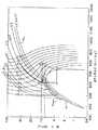
このCO2サイクルの作動は、原理的には、フロンを使用した従来の蒸気圧縮式冷凍サイクルの作動と同じである。すなわち、図1(CO2モリエル線図)のA−B−C−D−Aで示されるように、圧縮機で気相状態のCO2を圧縮し(A−B)、この高温高圧の超臨界状態のCO2を放熱器(ガスクーラ)にて冷却する(B−C)。そして、減圧器により減圧して(C−D)、気液2相状態となったCO2を蒸発させて(D−A)、蒸発潜熱を空気等の外部流体から奪って外部流体を冷却する。なお、CO2は、圧力が飽和液圧力(線分CDと飽和液線SLとの交点の圧力)を下まわるときから、気液2相状態に相変化するので、Cの状態からDの状態へとゆっくり変化する場合には、CO2は超臨界状態から液相状態を経て気液2相状態に変化する。
【0004】
因みに、超臨界状態とは、密度が液密度と略同等でありながら、CO2分子が気相状態のように運動する状態をいう。
しかし、CO2の臨界温度は約31℃と従来のフロンの臨界温度(例えば、R12では112℃)と比べて低いので、夏場等では放熱器側でのCO2温度がCO2の臨界点温度より高くなってしまう。つまり、放熱器出口側においてもCO2は凝縮しない(線分BCが飽和液線と交差しない)。
【0005】
また、放熱器出口側(C点)の状態は、圧縮機の吐出圧力と放熱器出口側でのCO2温度とによって決定され、放熱器出口側でのCO2温度は、放熱器の放熱能力と外気温度とによって決定する。そして、外気温度は制御することができないので、放熱器出口側でのCO2温度は、実質的に制御することができない。
したがって、放熱器出口側(C点)の状態は、圧縮機の吐出圧力(放熱器出口側圧力)を制御することによって制御可能となる。つまり、夏場等の外気温度が高い場合に、十分な冷却能力(エンタルピ差)を確保するためには、図1のE−F−G−H−Eで示されるように、放熱器出口側圧力を高くする必要がある。
【0006】
【発明が解決しようとする課題】
しかし、放熱器出口側圧力を高くするには、前述のように圧縮機の吐出圧力を高くしなければならないので、圧縮機の圧縮仕事(圧縮過程のエンタルピ変化量ΔL)が増加する。したがって、蒸発過程(D−A)のエンタルピ変化量Δiの増加量より圧縮過程(A−B)のエンタルピ変化量ΔLの増加量が大きい場合には、CO2サイクルの成績係数(COP=Δi/ΔL)が悪化する。
【0007】
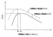
そこで、例えば放熱器出口側でのCO2温度を40℃として、放熱器出口側でのCO2圧力と成績係数と関係を図1を用いて試算すれば、図2の実線に示すように、圧力P1(約10MPa)において成績係数が最大となる。同様に、放熱器出口側でのCO2温度を35℃とした場合には、図2の破線で示すように、圧力P2(約9.0MPa)において成績係数が最大となる。
【0008】
以上のようにして、放熱器出口側のCO2温度と成績係数が最大となる圧力とを算出し、この結果を図1上に描けば、図1の太い実線ηmax(以下、最適制御線と呼ぶ。)に示すようになる。
したがって、上記CO2サイクルを効率良く運転するには、放熱器出口側圧力と放熱器出口側のCO2温度とを、最適制御線ηmaxで示されるように制御する圧力制御弁が必要である。
【0009】
なお、図1のモリエル線図は、AMERICAN SOCIETY OF HEATING,REFRIGERATING AND AIR−CONDITIONING ENGINEERSより出版されたFundamentals Handbookからの抜粋である。本発明は、上記点に鑑み、超臨界域で作動する蒸気圧縮式冷凍サイクルが効率良く運転するように、放熱器出口側温度と放熱器出口側圧力とを制御する圧力制御手段を提供することを目的とする。
本発明の目的は、密閉空間(305)内外の温度の差を小さくすることができる圧力制御弁を提供することにある。
本発明の他の目的は、変位部材(306)の耐久性を向上させることができる圧力制御弁を提供することにある。
本発明のさらに他の目的は、形成部材(307)の薄肉化を図ることができる圧力制御弁を提供することにある。
【0010】
【課題を解決するための手段】
本発明は、上記目的を達成するために、以下の技術的手段を用いる。
請求項1に記載の発明では、放熱器(2)内の圧力が冷媒の臨界圧力を越える蒸気圧縮式冷凍サイクルに適用され、前記放熱器(2)出口側の冷媒温度に応じて前記放熱器(2)出口側圧力を制御する圧力制御弁であって、
前記冷媒流路(6a)内に形成され、前記冷媒流路(6a)を上流側空間(301e)と下流側空間(301f)とに仕切る隔壁部(302)と、前記隔壁部(302)に形成され、前記上流側空間(301e)と前記下流側空間(301f)と連通させる弁口(303)と、密閉空間(305)内外の圧力差に応じて変位する、薄膜状の変位部材(306)と、前記変位部材(306)の厚み方向一端側に配設され、前記変位部材(306)と共に前記密閉空間(305)を形成する形成部材(307)と、前記変位部材(306)の厚み方向他端側に配設され、前記形成部材(307)と共に前記変位部材(306)を保持固定する保持部材(308)と、前記変位部材(306)の厚み方向他端側にて前記変位部材(306)に接触し、前記変位部材(306)に連動して変位し、前記弁口(303)を開閉する弁体(304)と、前記形成部材(307)に形成され、その肉厚方向に前記形成部材(307)から突出する突出部(317)とを備えていることを特徴とする圧力制御弁を採用する。
この発明によると、形成部材(307)の熱伝達率、および形成部材(307)の耐圧強度を向上させることができるので、形成部材(307)の薄肉化を図ることができる。
請求項4に記載の発明では、密閉空間(305)内外に渡って形成部材(307)を貫通し、形成部材(307)より熱伝導率の大きい材料からなる貫通部材(313)を備え、かつ、密閉空間(305)内には冷媒が、弁口(303)が閉じられた状態における密閉空間(305)内体積に対して、冷媒の温度が0℃での飽和液密度から冷媒の臨界点での飽和液密度に至る範囲の密度で封入されていることを特徴とする。
【0011】
これにより、密閉空間(305)内の冷媒圧力と冷媒温度との特性が、後述するように最適制御線ηmaxにほぼ一致する。したがって、圧力制御弁(3)は、放熱器(2)の出口側圧力を、ほぼ最適制御線ηmax上に沿った圧力まで上昇させた後、弁口(303)を開く。
つまり、放熱器(2)の出口側圧力と放熱器(2)の出口側温度とは、ほぼ最適制御線ηmax上に沿って制御されるので、超臨界域においても蒸気圧縮式サイクルを効率良く運転させることができる。
【0012】
また、形成部材(307)より熱伝導率の大きい材料からなる貫通部材(313)が、密閉空間(305)内外に渡って形成部材(307)を貫通して配設されているので、密閉空間(305)内の温度と上流側空間(301e)の温度との差を小さくすることができる。したがって、放熱器(2)の出口側圧力を、より一層最適制御線ηmaxに沿った圧力まで上昇させるので、より効率良く、CO2サイクルを運転させることができる。
【0013】
請求項5に記載の発明では、弁体(304)および変位部材(306)は、変位部材(306)が中立状態から変位部材(306)の厚み方向他端側に向けて変位したときに弁口(303)を閉じ、厚み方向一端側に向けて変位したときに弁口(303)の開度が最大となるように構成され、かつ、密閉空間(305)内には冷媒が、弁口(303)が閉じられた状態における密閉空間(305)内体積に対して、冷媒の温度が0℃での飽和液密度から前記冷媒の臨界点での飽和液密度に至る範囲の密度で封入されていることを特徴とする。
【0014】
これにより、変位部材(306)は中立状態から変位部材(306)の厚み方向他端側および一方側に変形変位することとなるので、弁体(303)の最大変位量に比べて、変位部材(306)の最大変形変位量を小さくすることができる。
したがって、変位部材(306)を中立状態から厚み方向一方側および他方側のいずれか一方側のみで変形変位させる場合に比べて、変位部材(306)に発生する最大応力を小さくすることができるので、変位部材(306)の耐久性を向上させつつ、超臨界域においても蒸気圧縮式サイクルを効率良く運転させることができる。
【0015】
なお、変位部材(306)が中立状態であるとは、変位部材(306)が変形変位しておらず、変形変位に伴う応力が略0の状態をいう。
請求項6に記載の発明では、形成部材(307)の肉厚方向に突出する突出部(317)が形成部材(307)に形成され、かつ、密閉空間(305)内には冷媒が、弁口(303)が閉じられた状態における密閉空間(305)内体積に対して、冷媒の温度が0℃での飽和液密度から冷媒の臨界点での飽和液密度に至る範囲の密度で封入されていることを特徴とする。
【0016】
これにより、形成部材(307)と上流側空間(301e)との間の熱伝達率、および形成部材(307)の耐圧強度を向上させることができるので、形成部材(307)の薄肉化を図ることができる。したがって、上流側空間(301e)と密閉空間(305)との熱伝導量を向上させつつ、超臨界域においても蒸気圧縮式サイクルを効率良く運転させることができる。
【0017】
なお、上記各手段の括弧内の符号は、後述する実施形態記載の具体的手段との対応関係を示すものである。
【0018】
【発明の実施の形態】
(第1実施形態)
図3は本実施形態に係る圧力制御弁を用いたCO2サイクルを車両用空調装置に適用したものであり、1は気相状態のCO2を圧縮する圧縮機である。2は圧縮機1で圧縮されたCO2を外気等との間で熱交換して冷却する放熱器(ガスクーラ)であり、3は放熱器2出口側でのCO2温度に応じて放熱器2出口側圧力を制御する圧力制御弁である。なお、圧力制御弁3は、放熱器2出口側圧力を制御するとともに減圧器を兼ねており、CO2は、この圧力制御弁3にて減圧されて低温低圧の気液2相状態のCO2となる。
【0019】
4は、車室内の空気冷却手段をなす蒸発器(吸熱器)で、気液2相状態のCO2は蒸発器4内で気化(蒸発)する際に、車室内空気から蒸発潜熱を奪って車室内空気を冷却する。5は、気相状態のCO2と液相状態のCO2とを分離するとともに、液相状態のCO2を一時的に蓄えるアキュームレータ(タンク手段)である。
【0020】
そして、圧縮機1、放熱器2、圧力制御弁3、蒸発器4およびアキュームレータ5は、それぞれ配管6によって接続されて閉回路を形成している。なお、圧縮機1は、図示されていない駆動源(エンジン、モータ等)から駆動力を得て駆動し、放熱器2は、放熱器2内CO2と外気との温度差をできるだけ大きくするために車両前方に配置されている。
【0021】
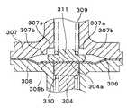
次に、圧力制御弁3の詳細構造について図4を用いて述べる。
301は放熱器2から蒸発器4に至るCO2流路6aの一部を形成するとともに、後述するエレメントケース315を収納するケーシングであり、301aは放熱器2側に接続される流入口301bを有する上蓋であり、301cは蒸発器4側に接続される流出口301dを有するケーシング本体である。
【0022】
また、ケーシング301には、CO2流路6aを上流側空間301eと下流側空間301fとに仕切る隔壁部302が配設されており、この隔壁部302には、上流側空間301eと下流側空間301fとを連通させる弁口303が形成されている。
そして、弁口303は、針状のニードル弁体(以下、弁体と略す。)304により開閉され、この弁体303および後述するダイヤフラム306は、ダイヤフラム306の変位に連動して、ダイヤフラム306が中立状態から弁体303側(ダイヤフラム306の厚み方向他端側)に向けて変位したときに弁口303を閉じ、厚み方向一端側に向けて変位したときに弁口303の開度(弁口303を閉じた状態を基準とする弁体304の変位量)が最大となるように構成されている。
【0023】
また、上流側空間301eには、密閉空間(ガス封入室)305が形成されており、この密閉空間305は、密閉空間305内外の圧力差に応じて変形変位する、ステンレス材からなる薄膜状のダイヤフラム(変位部材)306、およびダイヤフラム306の厚み方向一端側に配設されたダイヤフラム上側支持部材(形成部材)307から形成されている。
【0024】
一方、ダイヤフラム306の厚み方向他端側には、ダイヤフラム上側支持部材(以下、上側支持部材と略す。)307と共にダイヤフラム306を保持固定するダイヤフラム下側支持部材(保持部材)308が配設されており、このダイヤフラム下側支持部材(以下、下側支持部材と略す。)308のうち、ダイヤフラム306に形成された変形促進部(変位部材変形部)306aに対応する部位には、図5、6に示すように、変形促進部306aに沿う形状に形成された凹部(保持部材変形部)308aが形成されている。
【0025】
なお、変形促進部306aとは、ダイヤフラム306の径外方側の一部を波状に変形させたもので、ダイヤフラム306が密閉空間305内外の圧力差に略比例して変形変位するようにするためのものである。
また、下側支持部材308のうちダイヤフラム306に面する部位には、弁口303が弁体304により閉じられた状態において、弁体304のうちダイヤフラム306に接触する面304aに対して略同一面となる下側平面部(保持部材平面部)308bが形成されている。
【0026】
また、ダイヤフラム306の厚み方向一端側(密閉空間305内)には、図4に示すように、ダイヤフラム306を介して弁体304に対して弁口303を閉じる向きの弾性力を作用させる第1コイルばね(第1弾性部材)309が配設されており、一方、ダイヤフラム306の厚み方向他端側には、弁体304に対して弁口303を開く向きの弾性力を作用させる第2コイルバネ(第2弾性部材)310が配設されている。
【0027】
また、311は第1コイルばね309のばね座を兼ねるプレート(剛体)であり、このプレート311は、ダイヤフラム306より剛性が高くなるように所定の厚みを有して金属にて構成されている。そして、プレート311は、図5、6に示すように、上側支持部材307に形成された段付き部(ストッパ部)307aに接触することにより、ダイヤフラム306が、その厚み方向一端側(密閉空間305側)に向けて所定値以上に変位することを規制している。
【0028】
そして、上側支持部材307には、プレート311と段付き部307aとが接触したときに、プレート311のうちダイヤフラム306に接触する面311aに対して略同一面となる上側平面部(形成部材平面部)307bが形成されている。因みに、上側支持部材307の円筒部307cの内壁は、第1コイルばね309の案内部をも兼ねている。
【0029】
なお、プレート311および弁体304は、両コイルばね309、310により互いにダイヤフラム306に向けて押し付けられているので、プレート311、弁体304およびダイヤフラム306は互いに接触した状態で一体的に変位(稼働)する。
ところで、図4中、312は第2コイルばね310が弁体304に対して作用させる弾性力を調節するとともに、第2コイルばね310のプレートを兼ねる調節ネジ(弾性力調節機構)であり、この調節ネジ312は、隔壁部302に形成された雌ねじ302aにネジ結合している。因みに、両コイルバネ309、310による初期荷重(弁口303を閉じた状態での弾性力)は、ダイヤフラム306での圧力換算で約1MPaである。
【0030】
また、313は密閉空間305内外に渡って上側支持部材307を貫通し、密閉空間305内にCO2を封入するための封入管(貫通部材)であり、この封入管313は、ステンレス製の上側支持部材307より熱伝導率の大きい銅等の材料から構成されている。なお、下側支持部材308もステンレス製である。
そして、封入管313は、弁口303が閉じられた状態における密閉空間305内体積に対して約600kg/m3 の密度で封入した後、その端部を溶接等の接合手段により閉塞される。
【0031】
なお、314は、隔壁部302〜封入管313からなるエレメントケース315をケーシング本体301c内に固定する円錐ばねであり、316はエレメントケース315(隔壁部302)とケーシング本体301cとの隙間を密閉するOリングである。
因みに、図7の(a)はエレメントケース315のA矢視図であり、図7の(b)は(a)のB矢視図であり、図7から明らかなように、弁口303は隔壁部302の側面側にて上流側空間301eに連通している。
【0032】
次に、本実施形態に係る圧力制御弁3の作動を述べる。
密閉空間305内には、約600kg/m3 でCO2が封入されているので、密閉空間305内圧と温度とは、図1、8に示される600kg/m3 の等密度線に沿って変化する。したがって、例えば密閉空間305内温度が20℃の場合には、その内圧は約5.8MPaである。また、弁体304には、密閉空間305内圧と両コイルばね309、310による初期荷重とが同時に作用しているので、その作用圧力は約6.8MPaである。
【0033】
したがって、放熱器2側である上流側空間301eの圧力が6.8MPa以下の場合には、弁口303は弁体304によって閉止され、また、上流側空間301eの圧力が6.8MPaを越えると、弁口303は開弁する。
同様に、例えば密閉空間12内温度が40℃の場合には、密閉空間305内圧は図8より約9.7MPaであり、弁体304に作用する作用力は約10.7MPaである。したがって、上流側空間301eの圧力が10.7MPa以下の場合には、弁口303は弁来304によって閉止され、また、上流側空間301eの圧力が10.7MPaを越えると、弁口303は開弁する。
【0034】
次に、CO2サイクルの作動を図8を用いて説明する。
ここで、例えば放熱器2の出口側温度が40℃、かつ、放熱器2出口圧力が10.7MPa以下のときは、前述のように、圧力制御弁3は閉じているので、圧縮機1は、アキュームレータ5内に蓄えられたCO2を吸引して放熱器2へ向けて吐出する。これにより、放熱器2の出口側圧力が上昇していく(b’−c’→b”−c”)。
【0035】
そして遂に、放熱器2の出口側圧力が10.7MPaを越える(B−C)と圧力制御弁3が開弁するので、CO2は減圧しながら気相状態から気液2相状態に相変化して(C−D)蒸発器4内に流れ込む。そして、蒸発器4内で蒸発して(D−A)空気を冷却した後、再びアキュームレータ5に還流する。このとき、放熱器2の出口側圧力が再び低下するので、圧力制御弁3は再び閉じる。
【0036】
すなわち、このCO2サイクルは、圧力制御弁3を閉じるにより、放熱器2の出口側圧力を所定の圧力まで昇圧させた後、CO2を減圧、蒸発させて空気を冷却するものである。
なお、放熱器2の出口側温度が20℃の場合も、前述の作動と同様に、圧力制御弁3は、放熱器2の出口側圧力を約6.8MPaまで昇圧させた後、開弁する。
【0037】
次に本実施形態の特徴を述べる。
上述のように、本実施形態に係る圧力制御弁3は、放熱器2の出口側圧力を所定の圧力まで昇圧させた後、開弁するものであり、その制御特性は、圧力制御弁3の密閉空間305の圧力特性に大きく依存する。
ところで、図1、8から明らかなように、超臨界域での600kg/m3 の等密度線は、「発明が解決しようとする課題」の欄で述べた最適制御線ηmaxにほぼ一致する。したがって、本実施形態に係る圧力制御弁3は、放熱器2の出口側圧力を、ほぼ最適制御線ηmaxに沿った圧力まで上昇させるので、超臨界域においてもCO2サイクルを効率良く運転させることができる。
【0038】
また、臨界圧力以下では、600kg/m3 の等密度線は、最適制御線ηmaxからのズレが大きくなるが、凝縮域なので密閉空間305の内圧は、飽和液線SLに沿って変化する。そして、両コイルばね309、310によって弁体304に初期荷重が与えられているので、約10℃の過冷却度(サブクール)を有する状態に制御される。したがって、臨界圧力以下であっても、CO2サイクルを効率良く運転させることができる。
【0039】
なお、実用的には、CO2温度が0℃での飽和液密度からCO2の臨界点での飽和液密度までの範囲で、密閉空間305内に封入することが望ましい。具体的にCO2では、450kg/m3 〜950kg/m3 であり(図8の一点鎖線D1とD2の間の範囲)、密閉空間305内体積と封入質量との関係は、図9の斜線に示す範囲である。
【0040】
ところで、エレメントケース315単体を大気中に放置したとき、すなわち組立て工程における密閉空間305内外の圧力差(大気圧と密閉空間305との圧力差)は、CO2サイクル(CO2流路6a)に圧力制御弁3を配設した場合における密閉空間305内外の圧力差(上流側空間301eと密閉空間305との圧力差)に比べて非常に大きいので、組立て工程にダイヤフラム306が破損する可能性が高い。
【0041】
これに対して、本実施形態では、下側支持部材308には、弁口303が弁体304により閉じられた状態において、弁体304の面304aに対して略同一面となる下側平面部308bが形成されているので、下側支持部材308と弁体304との間に段差が発生し難くく、下側平面部308bと面304aとが略同一平面上に位置することとなる。
【0042】
したがって、組立て工程中に、密閉空間305内外の圧力差が大きくなったときでも、下側平面部308bと面304aとの間でダイヤフラム306が大きく変形することを抑制することができるので、組立て工程にダイヤフラム306が破損することを防止できる。
また、同様に、下側支持部材308に、変形促進部306aに沿う形状に形成された凹部308aが形成されているので、組立て工程中に、密閉空間305内外の圧力差により変形促進部306aにてダイヤフラム306が大きく変形することを防止することができる。延いては、ダイヤフラム306が変形促進部306aにて破損することを防止できる。
【0043】
また、プレート311と段付き部307aとが接触したときに、上側平面部307bがプレート311の面311aと略同一面になるので、上流側空間301eの圧力が上昇して密閉空間305内外の圧力差が大きくなったときでも、下側平面部308bと同様に、上側平面部307bと面311aとの間でダイヤフラム306が大きく変形することを抑制することができ、ダイヤフラム306の破損を防止できる。
【0044】
また、弁体304およびダイヤフラム306は、ダイヤフラム306が中立状態から弁体304側(ダイヤフラム306の厚み方向他端側)に向けて変位したときに弁口303を閉じ、厚み方向一端側に向けて変位したときに弁口303の開度(弁口303を閉じた状態を基準とする弁体304の変位量)が最大となるように構成されているので、ダイヤフラム306は中立状態からダイヤフラム306の厚み方向他端側および一方側に変形変位することとなる。
【0045】
したがって、弁体304の最大変位量に比べて、ダイヤフラム306の最大変形変位量を小さくすることができるので、ダイヤフラム306を中立状態から厚み方向一方側および他方側のいずれか一方側のみで変形変位させる場合に比べて、ダイヤフラム306に発生する最大応力を小さくすることができる。延いては、ダイヤフラム306の耐久性を向上させることができる。
【0046】
また、弁体304には、ダイヤフラム306の厚み方向両端側から弾性力が作用しているので、弁体304とダイヤフラム306とを接着(接合)することなく、弁体304とダイヤフラム306とを一体的に可動(変位)させることができる。
ところで、溶接等のように熱を加えることにより、弁体304とダイヤフラム306とを接合した場合、ダイヤフラム306の結晶構造が変化し、ダイヤフラム306の変形変位特性が変化するおそれがある。
【0047】
これに対して、本実施形態では、弁体304とダイヤフラム306とが接合されていないので、ダイヤフラム306の変形変位特性が変化することを防止できる。
ところで、上述の作動および特徴の説明からも明らかなように、圧力制御弁3の密閉空間305内温度は、理想的には、放熱器2出口側温度(上流側空間301eの温度)に対して時間差無しに連動して変化することが望ましい。
【0048】
これに対して、本実施形態では、上側支持部材307より熱伝導率の大きい封入管313が、密閉空間305内外に渡って上側支持部材307を貫通しているので、密閉空間305内の温度と上流側空間301eの温度との差を小さくすることができる。したがって、放熱器2の出口側圧力を、より一層最適制御線ηmaxに沿った圧力まで上昇させるので、より効率良く、CO2サイクルを運転させることができる。
【0049】
(第2実施形態)
本実施形態は、図10、11に示すように、上側支持部材307の肉厚方向に突出する突出部317を上側支持部材307に形成したものである。
これにより、上側支持部材307と上流側空間301eとの間の熱伝達率、および上側支持部材307の耐圧強度を向上させることができる。延いては、上側支持部材307の薄肉化を図ることができるので、上流側空間301eと密閉空間305との熱伝導量を向上させることができる。
【0050】
なお、本実施形態では、突出部317を上側支持部材307の外壁側(上流側空間301e)側にのみ設けたが、本実施形態は、これに限定されるものではなく、上側支持部材307の内壁側(密閉空間305側)に突出部317を設けてもよい。
(第3実施形態)
本実施形態は、図12、13に示すように、第2コイルばね310を下流側空間301fに配設したものである。なお、図12は隔壁部302に雌ねじ302aを設けた例であり、図13はケーシング本体301cに雌ねじ302aを設けた例である。
【0051】
これにより、エレメントケース315をケーシング301内に収納した後であっても、流入口301bから六角レンチ等により調節ネジ312を回すことができる。
(第4実施形態)
本実施形態は、図14〜16に示すように、第1コイルばね309を廃止して、弁体304およびプレート(剛体)311とダイヤフラム306とを接合するとともに、弁口303を閉じる向きに第2コイルばね310の弾性力を弁体304に対して作用させたものである。なお、本実施形態では、弁体304に雄ねじを形成し、調節ネジ312に雌ねじを形成している。
【0052】
これにより、エレメントケース315(圧力制御弁3)の部品点数を削減することができるので、圧力制御弁3の製造原価低減を図るこのできる。
ところで、本発明に係る圧力制御弁は、CO2を使用した蒸気圧縮式冷凍サイクルに使用が限定されるものではなく、例えば、エチレン、エタン、酸化窒素等の超臨界域で使用する冷媒を用いた蒸気圧縮式冷凍サイクルにも適用することができる。
【0053】
また、アキュームレータ5を廃止しても、前述の蒸気圧縮式冷凍サイクルを実施することができる。この場合、蒸発器4内に残存する冷媒が吸引されて、アキュームレータ5を有するCO2サイクルと同様な作動を得ることができる。
因みに、本明細書において、例えば「弁体304とダイヤフラム306とが接触している」とは、弁体304とダイヤフラム306との間に、スペーサ(ワッシャ)等の別体部品は介在している場合も含む意味である。つまり、弁体304と別体部品であっても、弁体304と一体的に可動する場合には、その別体部品は弁体304の一部とみなすことができる。なお、プレート311ととダイヤフラム306との間に別体部品が介在する場合も同じである。
【0054】
また、第1〜3実施形態では、ダイヤフラム306と弁体304とを接合していなかったが、両者306、304を溶接や接着剤等により接合してもよい。これにより、弁体304を確実にダイヤフラム306に追従させて変位させることができる。
また、上述の実施形態では、プレート311を樹脂製としてもよい。
【図面の簡単な説明】
【図1】CO2のモリエル線図である。
【図2】成績係数(COP)と放熱器出口側圧力との関係を示すグラフである。
【図3】CO2サイクルの模式図である。
【図4】第1実施形態に係る圧力制御弁の断面図である。
【図5】開弁状態を示すダイヤフラム部分の拡大図である。
【図6】閉弁状態を示すダイヤフラム部分の拡大図である。
【図7】(a)は図4のA矢視図であり、(b)は(a)のB矢視図である。
【図8】蒸気圧縮式冷凍サイクルの作動を説明するための説明図である。
【図9】密閉空間内の体積と、この密閉空間内に封入されるCO2の質量との関係を示すグラフである。
【図10】第2実施形態に係る圧力制御弁の上側支持部材を示す図であり、(a)は上面図、(b)は断面図である。
【図11】第2実施形態に係る圧力制御弁の変形例を示す上側支持部材の正面図である。
【図12】第3実施形態に係る圧力制御弁の断面図である。
【図13】第3実施形態の変形例に係る圧力制御弁の断面図である。
【図14】第4実施形態に係る圧力制御弁の断面図である。
【図15】第4実施形態の変形例に係る圧力制御弁の断面図である。
【図16】第4実施形態の変形例に係る圧力制御弁の断面図である。
【符号の説明】
301…ケーシング、302…隔壁部、303…弁口、304…弁体、
305…密閉空間、306…ダイヤフラム(変位部材)、
307…ダイヤフラム上側支持部材(形成部材)、
307a…段付き部(ストッパ部)、
307b…上側平面部(形成部材平面部)、
308…ダイヤフラム下側支持部材(保持部材)、
308b…下側平面部(保持部材平面部)、
309…第1コイルばね(第1弾性部材)、
310…第2コイルバネ(第2弾性部材)、
311…プレート(剛体)、312…調節ネジ(弾性力調節機構)、
313…封入管(貫通部材)。[0001]
BACKGROUND OF THE INVENTION
The present invention relates to a pressure control valve that controls the pressure on the outlet side of a radiator of a vapor compression refrigeration cycle, and is suitable for use in a vapor compression refrigeration cycle that uses a refrigerant in a supercritical region such as carbon dioxide (CO2 ). It is.
[0002]
[Prior art]
In recent years, as one of countermeasures against defloning refrigerant used in a vapor compression refrigeration cycle, for example, a vapor compression refrigeration cycle using carbon dioxide (CO2 ) as described in Japanese Patent Publication No. 7-18602 (hereinafter referred to as JP-B-7-18602). , Abbreviated as CO2 cycle).
[0003]
The operation of this CO2 cycle is in principle the same as the operation of a conventional vapor compression refrigeration cycle using chlorofluorocarbon. That is, as shown by A-B-C-D- A in FIG. 1 (CO2 Mollier chart), compressing the CO2 in the vapor phase by a compressor (A-B), the high-temperature high-pressure super The critical state CO2 is cooled by a radiator (gas cooler) (BC). Then, the pressure is reduced by a pressure reducer (CD), CO2 in a gas-liquid two-phase state is evaporated (DA), and latent heat of evaporation is taken away from an external fluid such as air to cool the external fluid. . CO2 changes from the C state to the D state because the phase changes from the time when the pressure falls below the saturated liquid pressure (the pressure at the intersection of the line segment CD and the saturated liquid line SL) to the gas-liquid two-phase state. CO2 changes from a supercritical state through a liquid phase state to a gas-liquid two phase state.
[0004]
Incidentally, the supercritical state refers to a state in which CO2 molecules move like a gas phase state while the density is substantially equal to the liquid density.
However, the critical temperature of CO2 is about 31 ° C. and conventional flon critical temperature (e.g., R12 in 112 ° C.) is lower than a, CO2 temperature critical point temperature of CO2 at the radiator side in summer or the like It will be higher. That is, CO2 is not condensed even on the radiator outlet side (the line segment BC does not intersect with the saturated liquid line).
[0005]
The state of the radiator outlet side (point C) is determined by the discharge pressure of the compressor and the CO2 temperature at the radiator outlet side, and the CO2 temperature at the radiator outlet side is the heat dissipation capability of the radiator. And the outside air temperature. Since the outside air temperature cannot be controlled, the CO2 temperature at the radiator outlet side cannot be substantially controlled.
Therefore, the state of the radiator outlet side (point C) can be controlled by controlling the discharge pressure (radiator outlet side pressure) of the compressor. That is, in order to ensure a sufficient cooling capacity (enthalpy difference) when the outside air temperature is high in summer or the like, as shown by E-F-G-H-E in FIG. Need to be high.
[0006]
[Problems to be solved by the invention]
However, since the discharge pressure of the compressor must be increased as described above in order to increase the radiator outlet side pressure, the compression work of the compressor (the enthalpy change amount ΔL in the compression process) increases. Accordingly, enthalpy variation when the amount of increase in enthalpy variation ΔL of increase than the compression process (A-B) of .DELTA.i is large, CO2 cycle coefficient of performance of the evaporation process (D-A) (COP = Δi / ΔL) gets worse.
[0007]
Therefore, for example, assuming that the CO2 temperature on the radiator outlet side is 40 ° C. and the relationship between the CO2 pressure on the radiator outlet side and the coefficient of performance is calculated using FIG. 1, as shown by the solid line in FIG. The coefficient of performance becomes maximum at the pressure P1 (about 10 MPa). Similarly, when the CO2 temperature on the radiator outlet side is set to 35 ° C., the coefficient of performance becomes maximum at the pressure P2 (about 9.0 MPa) as shown by the broken line in FIG.
[0008]
As described above, the CO2 temperature at the outlet side of the radiator and the pressure at which the coefficient of performance is maximized are calculated. If this result is drawn on FIG. 1, the thick solid line ηmax (hereinafter referred to as the optimum control line) in FIG. Called as
Therefore, in order to efficiently operate the CO2 cycle, a pressure control valve that controls the radiator outlet side pressure and the radiator outlet side CO2 temperature as indicated by the optimum control line ηmax is required. .
[0009]
The Mollier diagram in FIG. 1 is an excerpt fromFundamentals Handbook published byAMERICA SOCIETY OF HEATING,REFRIGERATING AND AIR-CONDITIONING ENGINEERS. In view of the above points, the present invention provides pressure control means for controlling a radiator outlet side temperature and a radiator outlet side pressure so that a vapor compression refrigeration cycle operating in a supercritical region operates efficiently. With the goal.
An object of the present invention is to provide a pressure control valve capable of reducing the temperature difference between the inside and outside of the sealed space (305).
Another object of the present invention is to provide a pressure control valve capable of improving the durability of the displacement member (306).
Still another object of the present invention is to provide a pressure control valve capable of reducing the thickness of the forming member (307).
[0010]
[Means for Solving the Problems]
In order to achieve the above object, the present invention uses the following technical means.
In the first aspect of the present invention, the radiator is applied to a vapor compression refrigeration cycle in which the pressure in the radiator (2) exceeds the critical pressure of the refrigerant, and the radiator according to the refrigerant temperature on the outlet side of the radiator (2). (2) A pressure control valve for controlling the outlet side pressure,
A partition wall portion (302) formed in the coolant channel (6a) and partitioning the coolant channel (6a) into an upstream space (301e) and a downstream space (301f), and the partition wall portion (302) A thin-film displacement member (306) formed and displaced in accordance with the pressure difference between the inside and outside of the sealed space (305) and the valve port (303) communicating with the upstream space (301e) and the downstream space (301f). ), A forming member (307) disposed on one end side in the thickness direction of the displacement member (306) and forming the sealed space (305) together with the displacement member (306), and a thickness of the displacement member (306) A holding member (308) disposed on the other end in the direction and holding the displacement member (306) together with the forming member (307), and the displacement member on the other end in the thickness direction of the displacement member (306). In contact with (306) A valve body (304) that is displaced in conjunction with the displacement member (306) to open and close the valve port (303) and the forming member (307) are formed in the thickness direction of the forming member (307). A pressure control valve characterized by including a projecting portion (317) projecting from the head is adopted.
According to the present invention, since the heat transfer coefficient of the forming member (307) and the pressure resistance of the forming member (307) can be improved, the forming member (307) can be thinned.
In the invention according to
[0011]
As a result, the characteristics of the refrigerant pressure and the refrigerant temperature in the sealed space (305) substantially coincide with the optimum control line ηmax as described later. Therefore, the pressure control valve (3) increases the outlet side pressure of the radiator (2) to a pressure substantially along the optimum control line ηmax and then opens the valve port (303).
That is, since the outlet side pressure of the radiator (2) and the outlet side temperature of the radiator (2) are controlled substantially along the optimum control line ηmax , the vapor compression cycle is efficient even in the supercritical region. You can drive well.
[0012]
Further, since the penetrating member (313) made of a material having a higher thermal conductivity than the forming member (307) is disposed so as to penetrate the forming member (307) over the inside and outside of the sealed space (305), the sealed space The difference between the temperature in (305) and the temperature in the upstream space (301e) can be reduced. Therefore, since the outlet side pressure of the radiator (2) is further increased to a pressure along the optimum control line ηmax , the CO2 cycle can be operated more efficiently.
[0013]
According to the fifth aspect of the present invention, the valve body (304) and the displacement member (306) are disposed when the displacement member (306) is displaced from the neutral state toward the other end in the thickness direction of the displacement member (306). When the opening (303) is closed and displaced toward one end in the thickness direction, the opening degree of the valve opening (303) is maximized, and refrigerant is contained in the sealed space (305). With respect to the volume in the closed space (305) in the closed state (303), the refrigerant is sealed at a density ranging from the saturated liquid density at 0 ° C. to the saturated liquid density at the critical point of the refrigerant. It is characterized by.
[0014]
Accordingly, the displacement member (306) is deformed and displaced from the neutral state to the other end side and one side in the thickness direction of the displacement member (306), so that the displacement member is larger than the maximum displacement amount of the valve body (303). The maximum deformation displacement amount of (306) can be reduced.
Therefore, the maximum stress generated in the displacement member (306) can be reduced as compared with the case where the displacement member (306) is deformed and displaced only from one side of the thickness direction and the other side from the neutral state. The vapor compression cycle can be efficiently operated even in the supercritical region while improving the durability of the displacement member (306).
[0015]
Note that the displacement member (306) is in a neutral state means that the displacement member (306) is not deformed and the stress associated with the deformation displacement is substantially zero.
In the invention described in
[0016]
Thereby, since the heat transfer rate between the forming member (307) and the upstream space (301e) and the pressure resistance strength of the forming member (307) can be improved, the forming member (307) can be thinned. be able to. Therefore, it is possible to efficiently operate the vapor compression cycle even in the supercritical region while improving the heat conduction amount between the upstream space (301e) and the sealed space (305).
[0017]
In addition, the code | symbol in the bracket | parenthesis of each said means shows a corresponding relationship with the specific means of embodiment description later mentioned.
[0018]
DETAILED DESCRIPTION OF THE INVENTION
(First embodiment)
FIG. 3 shows an application of a CO2 cycle using a pressure control valve according to the present embodiment to a vehicle air conditioner.
[0019]
[0020]
The
[0021]
Next, the detailed structure of the
[0022]
In addition, a
The
[0023]
Further, a sealed space (gas filled chamber) 305 is formed in the
[0024]
On the other hand, a diaphragm lower support member (holding member) 308 that holds and fixes the
[0025]
The
Further, the portion of the
[0026]
Further, as shown in FIG. 4, a first elastic force is applied to one end side in the thickness direction of the diaphragm 306 (in the sealed space 305) so as to close the
[0027]
[0028]
When the
[0029]
Since the
In FIG. 4,
[0030]
The sealing
[0031]
Incidentally, FIG. 7A is a view as seen from an arrow A of the
[0032]
Next, the operation of the
Since CO2 is sealed at about 600 kg / m3 in the sealed
[0033]
Therefore, when the pressure in the
Similarly, for example, when the temperature in the sealed space 12 is 40 ° C., the internal pressure of the sealed
[0034]
Next, the operation of the CO2 cycle will be described with reference to FIG.
Here, for example, when the outlet side temperature of the
[0035]
Finally, when the pressure on the outlet side of the
[0036]
That is, in this CO2 cycle, the pressure on the outlet side of the
Even when the outlet side temperature of the
[0037]
Next, features of this embodiment will be described.
As described above, the
As is clear from FIGS. 1 and 8, the 600 kg / m3 isodensity line in the supercritical region substantially coincides with the optimum control line ηmax described in the section “Problems to be solved by the invention”. . Therefore, the
[0038]
At a critical pressure or lower, the isodensity line of 600 kg / m3 has a large deviation from the optimal control line ηmax, but since it is a condensation zone, the internal pressure of the sealed
[0039]
Practically, it is desirable to enclose in the sealed
[0040]
By the way, when the
[0041]
On the other hand, in the present embodiment, the
[0042]
Therefore, even when the pressure difference between the inside and outside of the sealed
Similarly, the
[0043]
Further, when the
[0044]
Further, the
[0045]
Therefore, since the maximum deformation displacement amount of the
[0046]
Further, since elastic force is applied to the
By the way, when the
[0047]
On the other hand, in this embodiment, since the
By the way, as apparent from the above description of the operation and characteristics, the temperature in the sealed
[0048]
On the other hand, in this embodiment, since the sealed
[0049]
(Second Embodiment)
In the present embodiment, as shown in FIGS. 10 and 11, a protruding
As a result, the heat transfer coefficient between the
[0050]
In the present embodiment, the protruding
(Third embodiment)
In the present embodiment, as shown in FIGS. 12 and 13, the
[0051]
Thereby, even after the
(Fourth embodiment)
In this embodiment, as shown in FIGS. 14 to 16, the
[0052]
Thereby, since the number of parts of the element case 315 (pressure control valve 3) can be reduced, the manufacturing cost of the
By the way, the use of the pressure control valve according to the present invention is not limited to the vapor compression refrigeration cycle using CO2. For example, a refrigerant used in a supercritical region such as ethylene, ethane, or nitrogen oxide is used. The present invention can also be applied to a conventional vapor compression refrigeration cycle.
[0053]
Even if the
Incidentally, in this specification, for example, “the
[0054]
Further, in the first to third embodiments, the
In the above-described embodiment, the
[Brief description of the drawings]
FIG. 1 is a Mollier diagram of CO2 .
FIG. 2 is a graph showing the relationship between coefficient of performance (COP) and radiator outlet side pressure.
FIG. 3 is a schematic diagram of a CO2 cycle.
FIG. 4 is a cross-sectional view of a pressure control valve according to the first embodiment.
FIG. 5 is an enlarged view of a diaphragm portion showing a valve open state.
FIG. 6 is an enlarged view of a diaphragm portion showing a valve closed state.
7A is a view as viewed from an arrow A in FIG. 4, and FIG. 7B is a view as viewed from an arrow B in FIG.
FIG. 8 is an explanatory diagram for explaining the operation of the vapor compression refrigeration cycle.
FIG. 9 is a graph showing the relationship between the volume in the sealed space and the mass of CO2 sealed in the sealed space.
10A and 10B are diagrams showing an upper support member of a pressure control valve according to a second embodiment, wherein FIG. 10A is a top view and FIG. 10B is a cross-sectional view.
FIG. 11 is a front view of an upper support member showing a modification of the pressure control valve according to the second embodiment.
FIG. 12 is a cross-sectional view of a pressure control valve according to a third embodiment.
FIG. 13 is a cross-sectional view of a pressure control valve according to a modification of the third embodiment.
FIG. 14 is a cross-sectional view of a pressure control valve according to a fourth embodiment.
FIG. 15 is a cross-sectional view of a pressure control valve according to a modification of the fourth embodiment.
FIG. 16 is a cross-sectional view of a pressure control valve according to a modification of the fourth embodiment.
[Explanation of symbols]
301 ... Casing, 302 ... Bulkhead, 303 ... Valve port, 304 ... Valve body,
305 ... Sealed space, 306 ... Diaphragm (displacement member),
307 ... Diaphragm upper support member (forming member),
307a: Stepped portion (stopper portion),
307b ... upper plane part (formation member plane part),
308 ... Diaphragm lower support member (holding member),
308b ... lower plane part (holding member plane part),
309 ... 1st coil spring (1st elastic member),
310 ... second coil spring (second elastic member),
311 ... Plate (rigid body), 312 ... Adjustment screw (elastic force adjustment mechanism),
313: Enclosed tube (penetrating member).
Claims (9)
Translated fromJapanese前記冷媒流路(6a)内に形成され、前記冷媒流路(6a)を上流側空間(301e)と下流側空間(301f)とに仕切る隔壁部(302)と、
前記隔壁部(302)に形成され、前記上流側空間(301e)と前記下流側空間(301f)と連通させる弁口(303)と、
密閉空間(305)内外の圧力差に応じて変位する、薄膜状の変位部材(306)と、
前記変位部材(306)の厚み方向一端側に配設され、前記変位部材(306)と共に前記密閉空間(305)を形成する形成部材(307)と、
前記変位部材(306)の厚み方向他端側に配設され、前記形成部材(307)と共に前記変位部材(306)を保持固定する保持部材(308)と、
前記変位部材(306)の厚み方向他端側にて前記変位部材(306)に接触し、前記変位部材(306)に連動して変位し、前記弁口(303)を開閉する弁体(304)と、
前記形成部材(307)に形成され、その肉厚方向に前記形成部材(307)から突出する突出部(317)とを備えていることを特徴とする圧力制御弁。This is applied to a vapor compression refrigeration cycle in which the pressure in the radiator (2) exceeds the critical pressure of the refrigerant, and the pressure on the outlet side of the radiator (2) is controlled according to the refrigerant temperature on the outlet side of the radiator (2). A pressure control valve,
A partition wall (302) formed in the refrigerant channel (6a) and dividing the refrigerant channel (6a) into an upstream space (301e) and a downstream space (301f);
A valve port (303) formed in the partition wall (302) and communicating with the upstream space (301e) and the downstream space (301f);
A thin film-like displacement member (306) that is displaced according to a pressure difference between the inside and outside of the sealed space (305);
A forming member (307) disposed on one end in the thickness direction of the displacement member (306) and forming the sealed space (305) together with the displacement member (306);
A holding member (308) disposed on the other end side in the thickness direction of the displacement member (306) and holding and fixing the displacement member (306) together with the forming member (307);
A valve element (304) that contacts the displacement member (306) at the other end in the thickness direction of the displacement member (306), is displaced in conjunction with the displacement member (306), and opens and closes the valve port (303). )When,
A pressure control valve, comprising: a protrusion (317) formed on the forming member (307) and protruding from the forming member (307) in a thickness direction thereof.
前記冷媒流路(6a)内に形成され、前記冷媒流路(6a)を上流側空間(301e)と下流側空間(301f)とに仕切る隔壁部(302)と、
前記隔壁部(302)に形成され、前記上流側空間(301e)と前記下流側空間(301f)と連通させる弁口(303)と、
前記上流側空間(301e)内に密閉空間(305)を形成し、前記密閉空間(305)内外の圧力差に応じて変位する、薄膜状の変位部材(306)と、
前記変位部材(306)の厚み方向一端側に配設され、前記変位部材(306)と共に前記密閉空間(305)を形成する形成部材(307)と、
前記変位部材(306)の厚み方向他端側に配設され、前記形成部材(307)と共に前記変位部材(306)を保持固定する保持部材(308)と、
前記変位部材(306)の厚み方向他端側にて前記変位部材(306)に接触し、前記変位部材(306)に連動して変位し、前記弁口(303)を開閉する弁体(304)と、
前記密閉空間(305)内外に渡って前記形成部材(307)を貫通し、前記形成部材(307)より熱伝導率の大きい材料からなる貫通部材(313)とを備え、
前記密閉空間(305)内には冷媒が、前記弁口(303)が閉じられた状態における前記密閉空間(305)内体積に対して、前記冷媒の温度が0℃での飽和液密度から前記冷媒の臨界点での飽和液密度に至る範囲の密度で封入されていることを特徴とする圧力制御弁。This is applied to a vapor compression refrigeration cycle in which the pressure in the radiator (2) exceeds the critical pressure of the refrigerant, and is disposed in the refrigerant flow path (6a) from the radiator (2) to the evaporator (4). A pressure control valve for controlling the pressure on the outlet side of the radiator (2) according to the refrigerant temperature on the outlet side (2),
A partition wall (302) formed in the refrigerant channel (6a) and dividing the refrigerant channel (6a) into an upstream space (301e) and a downstream space (301f);
A valve port (303) formed in the partition wall (302) and communicating with the upstream space (301e) and the downstream space (301f);
A thin-film displacement member (306) that forms a sealed space (305) in the upstream space (301e) and is displaced according to a pressure difference between the inside and outside of the sealed space (305);
A forming member (307) disposed on one end in the thickness direction of the displacement member (306) and forming the sealed space (305) together with the displacement member (306);
A holding member (308) disposed on the other end side in the thickness direction of the displacement member (306) and holding and fixing the displacement member (306) together with the forming member (307);
A valve element (304) that contacts the displacement member (306) at the other end in the thickness direction of the displacement member (306), is displaced in conjunction with the displacement member (306), and opens and closes the valve port (303). )When,
A penetrating member (313) made of a material having a higher thermal conductivity than the forming member (307), penetrating the forming member (307) over the inside and outside of the sealed space (305),
The refrigerant in the sealed space (305) has a temperature of 0 ° C. from the saturated liquid density with respect to the volume in the sealed space (305) in a state where the valve port (303) is closed. A pressure control valve that is sealed at a density in a range that reaches a saturated liquid density at a critical point of the refrigerant.
前記冷媒流路(6a)内に形成され、前記冷媒流路(6a)を上流側空間(301e)と下流側空間(301f)とに仕切る隔壁部(302)と、
前記隔壁部(302)に形成され、前記上流側空間(301e)と前記下流側空間(301f)と連通させる弁口(303)と、
前記上流側空間(301e)内に密閉空間(305)を形成し、前記密閉空間(305)内外の圧力差に応じて変形変位する、薄膜状の変位部材(306)と、
前記変位部材(306)の厚み方向一端側に配設され、前記変位部材(306)と共に前記密閉空間(305)を形成する形成部材(307)と、
前記変位部材(306)の厚み方向他端側に配設され、前記形成部材(307)と共に前記変位部材(306)を保持固定する保持部材(308)と、
前記変位部材(306)の厚み方向他端側にて前記変位部材(306)に接触し、前記変位部材(306)に連動して変位し、前記弁口(303)を開閉する弁体(304)とを備え、
前記弁体(304)および前記変位部材(306)は、前記変位部材(306)が中立状態から前記変位部材(306)の厚み方向他端側に向けて変位したときに前記弁口(303)を閉じ、厚み方向一端側に向けて変位したときに前記弁口(303)の開度が最大となるように構成されており、
さらに、前記密閉空間(305)内には冷媒が、前記弁口(303)が閉じられた状態における前記密閉空間(305)内体積に対して、前記冷媒の温度が0℃での飽和液密度から前記冷媒の臨界点での飽和液密度に至る範囲の密度で封入されていることを特徴とする圧力制御弁。This is applied to a vapor compression refrigeration cycle in which the pressure in the radiator (2) exceeds the critical pressure of the refrigerant, and is disposed in the refrigerant flow path (6a) from the radiator (2) to the evaporator (4). A pressure control valve for controlling the pressure on the outlet side of the radiator (2) according to the refrigerant temperature on the outlet side (2),
A partition wall (302) formed in the refrigerant channel (6a) and dividing the refrigerant channel (6a) into an upstream space (301e) and a downstream space (301f);
A valve port (303) formed in the partition wall (302) and communicating with the upstream space (301e) and the downstream space (301f);
A thin-film displacement member (306) that forms a sealed space (305) in the upstream space (301e) and deforms and displaces according to a pressure difference between the inside and outside of the sealed space (305);
A forming member (307) disposed on one end in the thickness direction of the displacement member (306) and forming the sealed space (305) together with the displacement member (306);
A holding member (308) disposed on the other end side in the thickness direction of the displacement member (306) and holding and fixing the displacement member (306) together with the forming member (307);
A valve element (304) that contacts the displacement member (306) at the other end in the thickness direction of the displacement member (306), is displaced in conjunction with the displacement member (306), and opens and closes the valve port (303). )
The valve body (304) and the displacement member (306) are arranged so that the valve port (303) is formed when the displacement member (306) is displaced from the neutral state toward the other end in the thickness direction of the displacement member (306). And the opening of the valve port (303) is maximized when displaced toward one end in the thickness direction,
Further, the refrigerant in the sealed space (305) has a saturated liquid density at a temperature of 0 ° C. with respect to the volume in the sealed space (305) in a state where the valve port (303) is closed. To a saturated liquid density at a critical point of the refrigerant.
前記冷媒流路(6a)内に形成され、前記冷媒流路(6a)を上流側空間(301e)と下流側空間(301f)とに仕切る隔壁部(302)と、
前記隔壁部(302)に形成され、前記上流側空間(301e)と前記下流側空間(301f)と連通させる弁口(303)と、
前記上流側空間(301e)内に密閉空間(305)を形成し、前記密閉空間(305)内外の圧力差に応じて変位する、薄膜状の変位部材(306)と、
前記変位部材(306)の厚み方向一端側に配設され、前記変位部材(306)と共に前記密閉空間(305)を形成する形成部材(307)と、
前記変位部材(306)の厚み方向他端側に配設され、前記形成部材(307)と共に前記変位部材(306)を保持固定する保持部材(308)と、
前記変位部材(306)の厚み方向他端側にて前記変位部材(306)に接触し、前記変位部材(306)に連動して変位し、前記弁口(303)を開閉する弁体(304)と、
前記形成部材(307)に形成され、その肉厚方向に前記形成部材(307)から突出する突出部(317)とを備え、
前記密閉空間(305)内には冷媒が、前記弁口(303)が閉じられた状態における前記密閉空間(305)内体積に対して、前記冷媒の温度が0℃での飽和液密度から前記冷媒の臨界点での飽和液密度に至る範囲の密度で封入されていることを特徴とする圧力制御弁。This is applied to a vapor compression refrigeration cycle in which the pressure in the radiator (2) exceeds the critical pressure of the refrigerant, and is disposed in the refrigerant flow path (6a) from the radiator (2) to the evaporator (4). A pressure control valve for controlling the pressure on the outlet side of the radiator (2) according to the refrigerant temperature on the outlet side (2),
A partition wall (302) formed in the refrigerant channel (6a) and dividing the refrigerant channel (6a) into an upstream space (301e) and a downstream space (301f);
A valve port (303) formed in the partition wall (302) and communicating with the upstream space (301e) and the downstream space (301f);
A thin-film displacement member (306) that forms a sealed space (305) in the upstream space (301e) and is displaced according to a pressure difference between the inside and outside of the sealed space (305);
A forming member (307) disposed on one end in the thickness direction of the displacement member (306) and forming the sealed space (305) together with the displacement member (306);
A holding member (308) disposed on the other end side in the thickness direction of the displacement member (306) and holding and fixing the displacement member (306) together with the forming member (307);
A valve element (304) that contacts the displacement member (306) at the other end in the thickness direction of the displacement member (306), is displaced in conjunction with the displacement member (306), and opens and closes the valve port (303). )When,
A projecting portion (317) formed on the forming member (307) and projecting from the forming member (307) in the thickness direction;
The refrigerant in the sealed space (305) has a temperature of 0 ° C. from the saturated liquid density with respect to the volume in the sealed space (305) in a state where the valve port (303) is closed. A pressure control valve that is sealed at a density in a range that reaches a saturated liquid density at a critical point of the refrigerant.
前記変位部材(306)の厚み方向他端側に配設され、前記弁体(304)に対して前記弁口(303)を開く向きの弾性力を作用させる第2弾性部材(310)と、
前記第2弾性部材(310)が前記弁体(304)に対して作用させる弾性力を調節する弾性力調節機構(312)とを備えることを特徴とする請求項1ないし6のいずれか1つに記載の圧力制御弁。The displacement member (306) is disposed on one end side in the thickness direction, and applies an elastic force in a direction to close the valve port (303) to the valve body (304) via the displacement member (306). 1 elastic member (309);
A second elastic member (310) disposed on the other end side in the thickness direction of the displacement member (306) and acting on the valve body (304) in the direction of opening the valve port (303);
Any one ofclaims 1 to 6, characterized in that it comprises an elastic force adjustment mechanism (312) for adjusting the elastic force to be applied to said second elastic member (310) said valve body (304) The pressure control valve described in.
前記弾性部材(310)が前記弁体(304)に対して作用させる弾性力を調節する弾性力調節機構(312)とを備えることを特徴とする請求項1ないし6のいずれか1つに記載の圧力制御弁。An elastic member (310) that is bonded to the other end in the thickness direction of the displacement member (306) and applies an elastic force in a direction to close the valve port (303) to the valve body (304);
According to any one ofclaims 1 to 6, characterized in that said elastic member (310) comprises a resilient force and adjusting mechanism (312) for adjusting the elastic force to be applied to said valve body (304) Pressure control valve.
Priority Applications (4)
| Application Number | Priority Date | Filing Date | Title |
|---|---|---|---|
| JP19438497AJP3826503B2 (en) | 1997-07-18 | 1997-07-18 | Pressure control valve |
| DE69831534TDE69831534T2 (en) | 1997-07-18 | 1998-07-16 | Pressure control valve for refrigeration system |
| EP98113280AEP0892226B1 (en) | 1997-07-18 | 1998-07-16 | Pressure control valve for refrigerating system |
| US09/116,898US6012300A (en) | 1997-07-18 | 1998-07-17 | Pressure control valve for refrigerating system |
Applications Claiming Priority (1)
| Application Number | Priority Date | Filing Date | Title |
|---|---|---|---|
| JP19438497AJP3826503B2 (en) | 1997-07-18 | 1997-07-18 | Pressure control valve |
Publications (3)
| Publication Number | Publication Date |
|---|---|
| JPH1137615A JPH1137615A (en) | 1999-02-12 |
| JPH1137615A5 JPH1137615A5 (en) | 2006-01-12 |
| JP3826503B2true JP3826503B2 (en) | 2006-09-27 |
Family
ID=16323711
Family Applications (1)
| Application Number | Title | Priority Date | Filing Date |
|---|---|---|---|
| JP19438497AExpired - Fee RelatedJP3826503B2 (en) | 1997-07-18 | 1997-07-18 | Pressure control valve |
Country Status (1)
| Country | Link |
|---|---|
| JP (1) | JP3826503B2 (en) |
Families Citing this family (3)
| Publication number | Priority date | Publication date | Assignee | Title |
|---|---|---|---|---|
| JP4069548B2 (en)* | 1999-04-27 | 2008-04-02 | 株式会社デンソー | Control valve |
| JP2006266660A (en)* | 2004-11-19 | 2006-10-05 | Tgk Co Ltd | Expansion device |
| JP2008175417A (en)* | 2007-01-16 | 2008-07-31 | Calsonic Kansei Corp | Expansion valve |
- 1997
- 1997-07-18JPJP19438497Apatent/JP3826503B2/ennot_activeExpired - Fee Related
Also Published As
| Publication number | Publication date |
|---|---|
| JPH1137615A (en) | 1999-02-12 |
Similar Documents
| Publication | Publication Date | Title |
|---|---|---|
| JP4045654B2 (en) | Supercritical refrigeration cycle | |
| US6105386A (en) | Supercritical refrigerating apparatus | |
| EP0786632B1 (en) | Refrigerating system with pressure control valve | |
| JP3951840B2 (en) | Refrigeration cycle equipment | |
| US6134900A (en) | Supercritical refrigerating system | |
| JP4062129B2 (en) | Vapor compression refrigerator | |
| EP0892226B1 (en) | Pressure control valve for refrigerating system | |
| JPH10115470A (en) | Steam compression type regrigeration cycle | |
| JP4179231B2 (en) | Pressure control valve and vapor compression refrigeration cycle | |
| JP4254126B2 (en) | Ejector for vapor compression refrigeration cycle | |
| JP3467989B2 (en) | Vapor compression refrigeration cycle | |
| JP4196450B2 (en) | Supercritical refrigeration cycle | |
| JPH10288411A (en) | Vapor pressure compression type refrigerating cycle | |
| JP3826503B2 (en) | Pressure control valve | |
| JPH1163739A (en) | Pressure control valve | |
| JP3787968B2 (en) | Pressure control valve | |
| JP3867370B2 (en) | Refrigerating method | |
| JPH11148576A (en) | Pressure control valve | |
| JP4015171B2 (en) | Refrigerant condenser | |
| JP2005326145A (en) | Expansion device for refrigerant | |
| JP3711718B2 (en) | Pressure control valve | |
| JP2001108310A (en) | Pressure control device | |
| JP3879772B2 (en) | Refrigeration equipment | |
| JP2003121012A (en) | Method for controlling vapor compression type refrigerating cycle and vapor compression type refrigerating circuit in automotive air-conditioner | |
| JPH1163740A (en) | Pressure control valve |
Legal Events
| Date | Code | Title | Description |
|---|---|---|---|
| A521 | Request for written amendment filed | Free format text:JAPANESE INTERMEDIATE CODE: A523 Effective date:20051118 | |
| A977 | Report on retrieval | Free format text:JAPANESE INTERMEDIATE CODE: A971007 Effective date:20060222 | |
| A131 | Notification of reasons for refusal | Free format text:JAPANESE INTERMEDIATE CODE: A131 Effective date:20060307 | |
| A521 | Request for written amendment filed | Free format text:JAPANESE INTERMEDIATE CODE: A523 Effective date:20060428 | |
| TRDD | Decision of grant or rejection written | ||
| A01 | Written decision to grant a patent or to grant a registration (utility model) | Free format text:JAPANESE INTERMEDIATE CODE: A01 Effective date:20060613 | |
| A61 | First payment of annual fees (during grant procedure) | Free format text:JAPANESE INTERMEDIATE CODE: A61 Effective date:20060626 | |
| R150 | Certificate of patent or registration of utility model | Free format text:JAPANESE INTERMEDIATE CODE: R150 | |
| FPAY | Renewal fee payment (event date is renewal date of database) | Free format text:PAYMENT UNTIL: 20090714 Year of fee payment:3 | |
| FPAY | Renewal fee payment (event date is renewal date of database) | Free format text:PAYMENT UNTIL: 20100714 Year of fee payment:4 | |
| FPAY | Renewal fee payment (event date is renewal date of database) | Free format text:PAYMENT UNTIL: 20110714 Year of fee payment:5 | |
| FPAY | Renewal fee payment (event date is renewal date of database) | Free format text:PAYMENT UNTIL: 20120714 Year of fee payment:6 | |
| FPAY | Renewal fee payment (event date is renewal date of database) | Free format text:PAYMENT UNTIL: 20120714 Year of fee payment:6 | |
| FPAY | Renewal fee payment (event date is renewal date of database) | Free format text:PAYMENT UNTIL: 20130714 Year of fee payment:7 | |
| LAPS | Cancellation because of no payment of annual fees |