JP3825155B2 - Stencil printing machine - Google Patents
Stencil printing machineDownload PDFInfo
- Publication number
- JP3825155B2 JP3825155B2JP30252397AJP30252397AJP3825155B2JP 3825155 B2JP3825155 B2JP 3825155B2JP 30252397 AJP30252397 AJP 30252397AJP 30252397 AJP30252397 AJP 30252397AJP 3825155 B2JP3825155 B2JP 3825155B2
- Authority
- JP
- Japan
- Prior art keywords
- impression cylinder
- cylinder
- plate cylinder
- stencil printing
- printing apparatus
- Prior art date
- Legal status (The legal status is an assumption and is not a legal conclusion. Google has not performed a legal analysis and makes no representation as to the accuracy of the status listed.)
- Expired - Lifetime
Links
- 238000007639printingMethods0.000titleclaimsdescription69
- 230000002093peripheral effectEffects0.000claimsdescription29
- 230000008878couplingEffects0.000claimsdescription21
- 238000010168coupling processMethods0.000claimsdescription21
- 238000005859coupling reactionMethods0.000claimsdescription21
- 238000000926separation methodMethods0.000claimsdescription21
- 230000005540biological transmissionEffects0.000claimsdescription12
- 238000000034methodMethods0.000claimsdescription11
- 230000008569processEffects0.000claimsdescription8
- 238000003825pressingMethods0.000claimsdescription7
- 210000000078clawAnatomy0.000description24
- 238000010586diagramMethods0.000description9
- 230000033001locomotionEffects0.000description7
- 230000007246mechanismEffects0.000description7
- 238000004804windingMethods0.000description5
- 230000008859changeEffects0.000description4
- 238000012423maintenanceMethods0.000description4
- 238000004080punchingMethods0.000description3
- 230000001276controlling effectEffects0.000description2
- 239000011162core materialSubstances0.000description2
- 238000007599dischargingMethods0.000description2
- 230000001105regulatory effectEffects0.000description2
- 230000004044responseEffects0.000description2
- 239000000853adhesiveSubstances0.000description1
- 230000001070adhesive effectEffects0.000description1
- 238000005452bendingMethods0.000description1
- 238000007796conventional methodMethods0.000description1
- 230000000694effectsEffects0.000description1
- 239000013013elastic materialSubstances0.000description1
- 230000001747exhibiting effectEffects0.000description1
- 230000005484gravityEffects0.000description1
- 238000010438heat treatmentMethods0.000description1
- 230000007257malfunctionEffects0.000description1
- 238000002844meltingMethods0.000description1
- 230000008018meltingEffects0.000description1
- 239000002184metalSubstances0.000description1
- 230000004048modificationEffects0.000description1
- 238000012986modificationMethods0.000description1
- 230000000149penetrating effectEffects0.000description1
- 229920000728polyesterPolymers0.000description1
- 238000012545processingMethods0.000description1
- 239000007787solidSubstances0.000description1
- 230000001360synchronised effectEffects0.000description1
- 229920005992thermoplastic resinPolymers0.000description1
- 238000012546transferMethods0.000description1
- 230000000007visual effectEffects0.000description1
- 239000013585weight reducing agentSubstances0.000description1
Images


Classifications
- B—PERFORMING OPERATIONS; TRANSPORTING
- B41—PRINTING; LINING MACHINES; TYPEWRITERS; STAMPS
- B41L—APPARATUS OR DEVICES FOR MANIFOLDING, DUPLICATING OR PRINTING FOR OFFICE OR OTHER COMMERCIAL PURPOSES; ADDRESSING MACHINES OR LIKE SERIES-PRINTING MACHINES
- B41L13/00—Stencilling apparatus for office or other commercial use
- B41L13/16—Driving gear; Control thereof
Landscapes
- Rotary Presses (AREA)
- Impression-Transfer Materials And Handling Thereof (AREA)
Description
Translated fromJapanese【0001】
【発明の属する技術分野】
本発明は孔版印刷装置に関する。
【0002】
【従来の技術】
従来の孔版印刷装置の印刷部駆動系の要部を説明した図12において、版胴1は内部にインキ供給手段を有し穿孔製版済みのマスタ8の先端部をクランプ手段35により挾持して外周面部に装着した状態で回転するもので円筒状をなしている。圧胴14は図示を省略した給紙手段から1枚ずつ給紙される印刷用の用紙を周面に把持巻着の上、この用紙を版胴1に押圧しつつ版胴1の回転方向と反対の向きに回転駆動されるもので筒状をなしていて、その直径が版胴1の直径と略等しく形成されている。圧胴14と版胴1との間に印刷用の用紙がない状態でこれら圧胴14と版胴1とが接触するのは好ましくない。そこで、版胴1に対して圧胴14を前記した給紙のタイミングに合わせて接離動作させるべく接離手段70が設けられている。
【0003】
図13に示すように、圧胴14は圧胴軸14aに固定されている。圧胴軸14aの長手方向の両側はアーム25a、25bにそれぞれ設けられた軸受22a,22bに回転自在に支持されている。アーム25aの一端側は装置の側板23aに固定された軸27aに軸受26aを介して回動自在に支持されている。もう一つのアーム25bの一端側も同様に軸受26bを介して軸27bに回転可能に支持されている。この軸27bは装置の側板23bに設けた軸受28および該側板23bに取り付けられたカバー30に設けた軸受45により回転自在に支持されている。
【0004】
軸27bの一端側には、圧胴14の回転方向を版胴1の回転方向と逆向き、つまり対向面部で同一方向に移動するように調整するためのアイドルギヤとしてのギヤ41が固定されている。一方、圧胴軸14aのアーム25b側には、ギヤ41に噛み合うようにして圧胴ギヤ42が圧胴14に固定されている。軸27bのうち、カバー30内の部位には版胴1に回転力を伝える歯付きのプーリ44が固定されている。版胴1には該版胴1と一体的に歯付きのプーリ46が設けられており、また、このプーリ46と同心に歯付きのプーリ47がプーリ46と一体的に設けられている。プーリ47とプーリ44には歯付きのベルト43が巻き掛けられている。
【0005】
側板23a、23bには、軸受54a,54bを介して軸55が設けられており、この軸55には、カム53a,53bが固定されている。軸55は側板23bを貫通していて、この軸端部には歯付きのプーリ56が固定されている。モータ51の回転軸には歯付きのプーリ141が固定されている。プーリ141、46、56には歯付きのベルト48が掛けてある。これにより、モータ51が回転すると、ベルト48を介してプーリ46、56が回転し、版胴1とカム53a,53bとが同期して回転する。同時に、ベルト43を介してプーリ47、44が回転するので、圧胴14が版胴1と逆向きに同期して回転するとともに、カム53a、53bが回転する。
【0006】
圧胴14は、版胴1に当接する版胴1の直径と略等しい径の当接部14bと、該当接部より凹んだ非当接部14dとを有している。非当接部14dには、用紙を挾持するためのくわえ爪29が設けられている。このくわえ爪29は非当接部14dに配置された軸29aにその基端部を固着されていて、ばねにより常時閉じる向きに付勢されており、図示されないカムにより所定のタイミングで開閉される。印刷に際しては、版胴1に巻着されたマスタ8の移動とタイミングを合わせて用紙が圧胴14に向けて送られてくる。そして、予め開いた状態にあるくわえ爪29に用紙の先端部がくると、くわえ爪29は閉じて、該用紙の先端をくわえる。その後、カム53a,53bの回転に従う所定のタイミングでアーム25a,25bが揺動して、ばね49a,49bの力により圧胴14は用紙を介して版胴1に押しつけられて印刷が行なわれる。
【0007】
このように、印刷が行なわれている状態、つまり、用紙が版胴1と圧胴14との間に存在する状態のもとでは、圧胴14は版胴1に押しつけられていなければならないが、通常状態、つまり、電源オフ時や、給排版時において、用紙が版胴1と圧胴14との間に存在しない状態のもとでは、版胴1に圧胴14が直接接触すると版胴1の表面のインキが圧胴14に付着して印刷時に裏汚れなどの不都合を生ずるので、これを避けるため、圧胴14を版胴1から離間させなければならない。
【0008】
そこで、版胴1に対する圧胴14の接離を制御するために、接離手段70が設けられている。図12、図13において接離手段70は主として、軸27a,27bを中心として圧胴14を揺動させるアーム25a,25bと、これらのアーム25a,25bの他端側に枢着されたコロ52a、52bと、これらのアーム25a,25bを版胴1に向けて付勢するばね49a,49bと、コロ52a,52bに当接するカム53a,53b,フックレバー200a,200b,ステー204、ばね205,ソレノイド206等からなる。
【0009】
フックレバー200a、200bは、アーム25a,25bの各先端部に対して係脱自在の態様に設けられている。これらフックレバー200a、200bは側板23a,23bに固定された軸201a,201bに枢着されている。これらフックレバー200aとフックレバー200bとは、ステー204により連結されている。ステー204は軽量化のため厚さ0.6〜0.8mm程度の薄板を箱曲げにしたものが使用されている。
【0010】
このステー204の中央部は緊縮性のばね205で引かれるようになっていて、このばね205の弾性によりフックレバー200a,200bとアーム25a,25bとが係合され、そして、フックレバー200a、200bはアーム25a、25bを上方に付勢するばね49a、49bの力に抗するようにして、その係合状態は保持されるようになっている。ばね205の反対側にはソレノイド206が設けられていて、このソレノイド206がオンされてカム53a、53bの凸部であるy部がコロ52a,52bに当接する位置に回転すると、アーム25a、25bはばね49a、49bの力に抗して下方に若干下がり、フックレバー200a、200bとアーム25a、25bに僅かな隙間が発生するので、このときはじめて、ばね205の力に抗してフックレバー200a,200bが回動して、該フックレバー200a,200bのアーム25a,25bとの係合状態を解除する。
【0011】
この係合状態が解除された状態のもとでは、カム53a、53bにならい、ばね49a,49bの弾性によりアーム25a,25bが揺動して圧胴の当接部14bが版胴1に当接した状態となり、圧胴14は版胴1に押圧される態位と、版胴1から離間した態位とを交互にとるように制御されることとなる。
【0012】
印刷に際しては版胴1と圧胴14との間に印刷用の用紙が存在することとなるので、通紙の命令と同期して、カム53a,53bの凹部であるx部をコロ52a,52bに対向する状態として、用紙を介して圧胴14を版胴1に押圧させる。このとき、ばね49a,49bは圧胴14を版胴1に押圧する印圧力を発生させる。この印圧力は、アーム25aにばね49a、アーム25bにばね49bをそれぞれ取り付けていることで均一に働く。版胴1と圧胴14との間に用紙が介在する間は該用紙を介して圧胴14を版胴1に押圧した状態とし、用紙が通過してしまえばカム53a,53bの凸部であるy部をコロ52a,52bに対向する状態として圧胴14を版胴1から離間させる。このように、印刷中、圧胴14は用紙一枚毎にカム53a,53bに従って揺動する。
【0013】
【発明が解決しようとする課題】
▲1▼.以上に述べたとおり、アーム25a,25bは軸27a,27bを支点として揺動しこの揺動に伴い、アーム25a、25bに回転自在に設けられた圧胴14も用紙の1枚通過毎に揺動する。このように、軸27bを支点とするアーム25bの揺動に際して、圧胴ギヤ42はギヤ41に対して回動することとなる。
【0014】
図14において、圧胴14は反時計回りの向きに版胴1の周速度に等しい周速度を得るように定速回転されているものとする。圧胴14を版胴1から離間させるに際して、カム53a、53bの制御により、アーム25a、25bの自由端側を下げる場合を考えると、この下げる動作の間、揺動は軸27a、27bを回転中心として行われる。ギヤ41は軸27bに固定され、且つ、これに圧胴ギヤ42が噛み合い、これらのギヤの軸間距離は揺動しても変わらないので、遊星ギヤのようにギヤ41を中心に外周を圧胴ギヤ42が回転することとなる。よって、アーム25bが下がるときは、圧胴ギヤ42はギヤ41の外周に沿って下方に回転しながら移動し、このとき、圧胴ギヤ42は図14において、反時計回りの向きに回動する。圧胴ギヤ42は圧胴14と一体的であるので、圧胴14も圧胴ギヤ42と共に反時計回りの向きに同量回動する。このため、圧胴14の周速度はアーム25a、25bを下げる動作の間、版胴1の周速度にプラスして、揺動による圧胴ギヤ42の回転速度分、増速されることとなる。
【0015】
これと全く逆に、圧胴14を版胴1に押圧させるに際して、カム53a、53bの制御により、アーム25a、25bの自由端側を上げる場合を考えると、この上げる動作の間、圧胴ギヤ42はギヤ41の外周に沿って上方に回転しながら移動し、図15において時計回りの向きに回動する。圧胴ギヤ42は圧胴14と一体的であるので、圧胴14も圧胴ギヤ42と共に時計回りの向きに同量回動する。このため、圧胴14の周速度はアーム25a、25bを上げる動作の間、版胴1の周速度にマイナスして揺動による圧胴ギヤ42の回転速度分、減速されることとなる。
【0016】
圧胴14の非当接部14dには用紙をくわえるくわえ爪29がついており、後述するレジストローラ13(図10、図11を参照)より版胴1の周速度と同じ速度にて用紙が圧胴14に向けて送られる。ところが、上記のようにアーム25a、25bの揺動により圧胴14に周速度の変動が生ずると、用紙はくわえ爪29にタイミングよく、くわえられない場合を生じてしまう。実際の例では、アーム25a、25bが揺動することによる圧胴14の周速度の変動は、版胴の周速度の1.5倍程度となり、用紙のくわえ込みのミスを発生するおそれがある。
【0017】
▲2▼.圧胴14への駆動力の伝達は、圧胴ギヤ42とギヤ41との噛み合わせにより行なわれており、ギヤの1歯でも噛み合いの位置がずれると、版胴1のクランプ手段35と圧胴14のくわえ爪29との位置関係もずれてしまう。この関係位置がずれると、用紙上に印刷される画像の位置もずれてしまう。一方、圧胴14は表面が弾性体で製作されているなどして、排紙の際に、後述する排紙爪15(図10、図11を参照)により傷つく等のことから、これを修復するためメンテナンスが必要となる。このメンテナンスを終えて圧胴14を組み付けるに際し、前記したように、ギヤの噛み合わせが1歯でも違うと画像の位置ずれを生じてしまうのであるから、位置ずれが生じないように細心の注意が必要となり、組み付け作業は困難を伴う。
【0018】
本発明は、アーム25bが揺動するのに応じて該アーム25bに取り付けられた圧胴ギヤ42が、位置が固定されているギヤ41に対して遊星運動するために圧胴ギヤ42が回転させられ、該圧胴ギヤ42と一体的な圧胴14の周速度が変動し、用紙のくわえ込みのミスが発生するという問題をなくすることのできる孔版印刷装置を提供することを目的とする。
【0019】
また、本発明は、メンテナンス時における圧胴の組み付け作業性を向上させることのできる孔版印刷装置を提供することを目的とする。
【0020】
【課題を解決するための手段】
この発明は、上記目的を達成するため、以下の構成を採用した。
【0021】
(1)インキ供給手段を有し外周面部に穿孔製版済みのマスタを装着した状態で回転する円筒状の版胴と、給紙手段から1枚ずつ給紙される印刷用の用紙を周面に把持巻着の上、この用紙を前記版胴に押圧しつつ前記版胴の回転方向と反対の向きに回転駆動される筒状の圧胴と、前記版胴に対する前記圧胴の前記用紙のない状態での接触を避けるために前記版胴に対して前記圧胴を前記給紙のタイミングに合わせて接離動作させる接離手段と、を有する孔版印刷装置において、前記圧胴の駆動系を前記接離動作に影響されない不動部材に配置し、前記接離手段による前記圧胴の位置変動に拘らず前記接離動作の過程および前記接離動作の前後を通じて前記圧胴に速度変動を与えることなく前記圧胴を前記駆動系の回転状態に従うなめらな回転状態で動力伝達する伝達手段をもって前記駆動系と前記圧胴とを連結した(請求項1)。
【0022】
(2)(1)記載の孔版印刷装置において、前記伝達手段としてオールダム軸継手を用いた(請求項2)。
【0023】
(3)(2)記載の孔版印刷装置において、前記オールダム軸継手がスライダーとその両側にガイドフランジとを有し、前記スライダーに前記圧胴の駆動系側のガイドフランジとの係止を行なう係止フックを備えた(請求項3)。
【0024】
(4)(2)記載の孔版印刷装置おいて、前記オールダム軸継手がスライダーとその両側にガイドフランジとを有し、前記スライダーと前記圧胴側の前記ガイドフランジとに、双方の嵌合規制を行なう嵌合規制手段を備えた(請求項4)。
【0025】
【発明の実施の形態】
以下、本発明の実施例を図を参照しながら詳細に説明する。
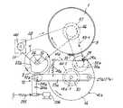
図1、図2において、従来技術として説明した図12、図13におけると同じ部材については、同じ符号を付して説明は省略し、異なる構成部分を主として説明する。図2において符号50aは歯付きのプーリを示す。このプーリ50aは不動部材である側板23b(図1参照)に回転自在に設けられたものである。このプーリ50aにはギヤ50bが一体的に設けられている。このギヤ50bはアイドルギヤであり、圧胴14の回転方向を版胴1の回転方向と合わせるためのものである。プーリ50aとプーリ46とは歯付きのベルト43−1で連結されている。ギヤ50bはギヤ44−1と噛み合わされている。
【0026】
側板23bには箱型のカバー30−1内にギヤ44−1が設けられている。ギヤ44−1は軸27b−1に固定されている。軸27b−1の一端側はカバー30−1に設けた軸受45−1に支持されている。軸27b−1の他端側は側板23bに設けた軸受28−1に支持された上、該軸受28−1を貫通して側板23bの内側に突出している。
【0027】
圧胴14の一方の側の軸である圧胴軸14a−1は軸受22a−1を介してアーム25aに支持されている。この圧胴軸14a−1はアーム25aを側板23a寄りにスライドしたときにもアーム25aによって支持がなされるように、軸受22a−1を貫通しており、従来と異なり側板23a側に延出している。圧胴14の他方の側の軸である圧胴軸14a−2は軸受22a−2を介して、アーム25bに支持されている。この圧胴軸14a−2についても、アーム25bよりも側板23b側に延出している。
【0028】
このように、側板23bよりも内側に突出した軸27b−1と、アーム25bよりも側板23b側に延出している圧胴軸14a−2の各軸心はアーム25bの任意の揺動態位において合致するように設けられている。
【0029】
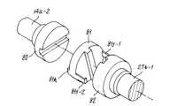
本例では、圧胴14の駆動系の一部をなす軸27b−1の回転を、圧胴14と一体的な圧胴軸14a−2に、なめらかな回転状態で動力伝達する伝達手段として、オールダム軸継手83を用いている。このオールダム軸継手83による連結の態様を説明すると、オールダム軸継手83は、図3に詳細に示すように圧胴軸14a−2にガイドフランジ80が取り付けられ、軸27b−1にガイドフランジ82が取り付けられ、これらガイドフランジ80とガイドフランジ82との間にスライダー81が挾まれるようにして取り付けられ、これらガイドフランジ80、82、スライダー81等によりオールダム軸継手83が構成されている。
【0030】
図1、図3、図5に示すように、スライダー81にはその両面に角形突起が互いに90度をなすように設けられ、これらの角形突起は、ガイドフランジ80、82に形成された溝に摺動自在に嵌合状態にある。このような嵌合により、軸27b−1と圧胴軸14a−2の軸芯が回転中にずれても、駆動側の軸27b−1が回転するとき、スライダー81はガイドフランジ80およびガイドフランジ82に対して摺動して楕円運動を描いて運動し、駆動側の軸27b−1の回転は回転速度変動を生じることなく圧胴軸14a−2に正確に伝達される。
【0031】
オールダム軸継手の変形として、図4に示すアメリカン軸継手83−1がある。このアメリカン軸継手の場合、圧胴軸14a−2に取り付けられたガイドフランジ80−1と、軸27b−1に取り付けられたガイドフランジ82−1と、これらガイドフランジ80−1とガイドフランジ82−1との間に介在するスライダー81−1とからなり、スライダー81−1がガイドフランジ80−1およびガイドフランジ82−1の各溝部に摺動自在に嵌合して上記のオールダム軸継手83と同じ機能を果たす。オールダム軸継手83もアメリカン軸継手83−1も機能的には略同じであるので、以下の説明ではオールダム軸継手83について説明する。なお、オールダム軸継手83に代えて、ユニバーサルジョイントを使用することも可能であるが、オールダム軸継手の方が、軸方向に大きなスペースを要しない点で有利である。
【0032】
駆動側である軸27b−1と従動側である圧胴軸14a−2との平行が保持されていれば軸心間の距離がずれても、動力伝達に際しての周速度差が発生しないのがオールダム軸継手の特徴であり、アーム25a、25bの揺動に伴う圧胴軸14a−2の揺動量は実際には1〜3mm程度であるので、圧胴14について実質的に問題とされるような周速度変動は発生しなくなる。ここで、モータ51、ベルト48、プーリ46、プーリ47、ベルト43−1、プーリ50a、ギヤ50b等からなる構成は圧胴14の駆動系の例であり、この例にかかる駆動系は前記したように、接離手段70によって行なわれる圧胴14の版胴1に対する接離動作に影響されない側板23a、23b等の不動部材に設けられている。
【0033】
次に、オールダム軸継手83を使用する孔版印刷装置において、圧胴14の分解組立ての容易性について場合を分けて説明する。
(a)圧胴を軸方向に移動させた上で軸直角方向に移動して分解するケース
図1、図5〜図7により説明する。
図1において、軸受22a−1、22a−2はともに大径部と小径部からなる段付きの形状で形成されている。また、圧胴軸14a−1、14a−2も大径部と小径部とからなる段付きの形状で形成されている。軸受22a−2についてその小径部はアーム25bの穴に嵌合され、該軸受22a−2の段部はアーム25bの左側端面に突き当てられている。圧胴軸14a−2についてその小径部は軸受22a−2に嵌合され、該圧胴軸14a−2の段部は軸受22a−2の大径部の側端面に突き当てられている。
【0034】
軸受22a−1の大径部の端面は圧胴軸14a−1の段部に突き当てられている。軸受22a−1の小径部はアーム25aの穴に嵌合されていて、該軸受22a−1の段部はアーム25aの右側端面に突き当てられている。また、このような組立て状態において、オールダム軸継手83における溝と角形突起とは摺動可能な嵌合状態にある。このような組立て状態が保持されるように、アーム25aは軸27aの軸長手方向上の位置を図示省略のEリング等適宜の位置決め手段により位置決めされており、また、アーム25bについても同様に、軸27bの軸長手方向上の位置をEリング等適宜の位置決め手段により位置決めされている。
【0035】
圧胴14を分解するに際しては、軸27a上でのアーム25aの位置を保持している位置決め手段としてのEリングなどを除去した後、アーム25aを軸27aに沿って側板23a寄りの向き、つまり、図5で左向きに移動させ、さらに圧胴14を左に移動させることにより、軸受22a−2を可動とするスペースを得て図5に示すようにアーム25bから軸受22a−2を外す。同時に該圧胴14の移動により、ガイドフランジ80とスライダー81の嵌合関係も解除させることができる。
【0036】
ここで、図6に示すように、軸受22a−2の小径部と嵌合しているアーム25bの穴25b−Hはその上方部分が圧胴軸14a−2の小径部14a−2−Sの通過を許す大きさで外方に連通開放されている。同様に図7に示すように、軸受22a−1の小径部と嵌合しているアーム25aの穴25a−Hはその上方部分が圧胴軸14a−1の小径部14a−1−Sの通過を許す大きさで外方に連通開放されている。よって、図5、図6、図7に示す状態で、圧胴14を図5における紙面に垂直な上方向に取り出して孔版印刷装置から分解することができる。
【0037】
なお、この圧胴14の分解に際して、ガイドフランジ80とスライダー81との嵌合位置は、ガイドフランジ80の溝およびスライダー81の角形突起とがこれらガイドフランジ80やスライダー81の中心と対称の形状に形成されていると、180度の組み違いをする可能性がある。そこで、ガイドフランジ80とスライダー81とに合いマークを付しておくことによりこの合いマークを基準として組み立てることにより、版胴1のクランプ手段35と圧胴14のくわえ爪29との位置関係のずれを生ずることなく、元通りに組み立てることができる。
【0038】
なお、合いマークが平面的なライン等で印された場合には、オペレータが視覚的に確認するにとどまるので、見誤る可能性がないとはいえない。そこで、ガイドフランジ80とスライダー81とに、それぞれ双方の嵌合規制を行なうべく、立体的な嵌合規制手段を設ければ、単なる平面的な合いマークよりも視認性が向上し、さらに確実にガイドフランジ80とスライダー81との180度の組み違いを防止することができる。
【0039】
図16、図17に示した例では、ガイドフランジ81側に形成した角形突起81hを、長手方向の途中から幅の広い部位から幅の狭い部位に変わる段部を形成した羽子板のような形状にしている。但し、スライドを可能にするため、長手方向各部での断面形状、大きさは、幅の広い部位、幅の狭い部位のそれぞれについて一定である。ガイドフランジ80についても、角形突起81hと相似形で嵌合可能な溝80hを形成している。また、スライダー81とガイドフランジ80の各中心を合致させたとき、角形突起81h及び溝80hにおけるそれぞれについての、幅の狭い部位から幅の広い部位との境目の段差部間は、所要量のスライドを確保するため、隙間αをおいている。
【0040】
このような形状で形成した角形突起81hと溝80hの組合せを嵌合規制手段と称する。このようにガイドフランジ80、スライダー81の中心に対して非対称の嵌合規制手段を設ければ、立体的な合いマークの機能を有することにより視認性が向上するとともに、常に一義的な位置関係をもって組み立てられることとなり、視認性がよいので180度の組み違いは生じにくいし、また、たとえ視認上の誤りがあったとしても、その場合には角形突起81hと溝80hとの嵌合関係が成立せず、組み立ての誤りは生じ得ない。
【0041】
なお、嵌合規制手段としては、図18に示すように、スライダー81やガイドフランジ80の中心から外れた位置に円形の膨らみを形成するとともに直径方向に延びる角形突起81h’と該角形突起81h’に嵌合する溝80h’とで構成することもできる。さらに、これらの例の外にも、オールダム軸継手としての機能を発揮し得るスライド可能な構成とし、かつ、スライダー81やガイドフランジ80の中心に対して非対称の形状からなる嵌合規制手段を構成することで、同様の作用上の利益を得ることができる。
【0042】
このように、嵌合規制手段は、ライン状の合いマークのように平面的でなく、立体的なマークとしての機能を有するので、圧胴の組み立て時における視認性が格段に向上し、視覚上の誤りが生じにくく、しかも、一義的に嵌合状態が定まることから信頼性が増し、組み立て性の向上を図ることができる。
【0043】
この圧胴14の分解に際して、アーム25aを左に移動することにともないコロ52aも左に移動することから、コロ52aとカム53aとの係合関係も外れ、アーム25aの自由端側が揺動して圧胴14の支持が不安定になることを防止するため、予めカム53aの凸部であるy部をコロ52aに対応させた状態のもとでソレノイド206をオフ状態にし、フックレバー200aによりアーム25aの先端部を係止させた状態にしておく。
【0044】
なお、アーム25aの移動ストロークの範囲においてこの係止の関係が保持される幅にアーム25aの自由端側を形成しているので、アーム25aの移動にともなってコロ52aがカム53aから外れてもアーム25aが揺動することはなく、安全である。圧胴14を左に移動させた時点で、既にガイドフランジ80の溝とスライダー81の角形突起との係合関係は解除されているので、アーム25a、25bと軸受22a−1、22a−2との係合が解除さえされれば、容易に圧胴14を装置本体から取り外すことができる。また、組立てに際しては、分解の場合と逆の手順を踏むことにより容易に元通りに組み立てることができる。
【0045】
(b)圧胴を軸直角方向に移動するだけで分解するケース
オールダム軸継手83では、係合状態にあるガイドフランジ80の溝とスタイダー81の角形突起を、これらの溝および角形突起の摺動方向にずらすことにより分解することができる。従って、アーム25a、25bに対する圧胴軸14a−1、14a−2の拘束を解除して軸直角方向に解放できれば、前記(a)の例におけるように圧胴14を軸方向に移動させることなしに容易に圧胴14を分解することができる。
【0046】
本例では、アーム25a,25bに対する圧胴軸14a−1、14a−2の拘束を解除する手段として、圧胴軸14a−1、14a−2を軸受22a−1、22a−2と一緒にアーム25a,25bから軸直角方向に取り出せるようにした。つまり、アーム25bと軸受22a−2との係合保持状態を簡単に解除する手段として、図8に示すようにアーム25bにU字状の穴25b−Uを形成して、軸受22a−2を穴25b−Uに嵌合した上で、上からキャップ25b−U1を被せて、ねじ84により締め付け固定する構成とした。また、図9に示すようにアーム25aにU字状の穴25a−Uを形成して、軸受22a−1を穴25a−Uに嵌合した上で、上からキャップ25a−U1を被せて、ねじ84により締め付け固定する構成とした。
【0047】
このような構成を採用することにより、キャップ25a−U1、25b−U1をそれぞれのアーム25a,25bから外すだけで、圧胴14を孔版印刷装置から分解することができるし、組立てにおいても分解時と逆の手順を踏むことにより容易に組み立てることができる。
【0048】
なお、前述した(a)と(b)のそれぞれの、分解するケースにおけるオールダム軸継手83は、圧胴14を軸直角方向である上方に取り出せるようにしているので、その方向にガイドフランジ80の溝とスライダー81の角形突起を位置させると、スライダー81の他方の角形突起は90度向きが違ってガイドフランジ82の溝と嵌合しているため、スライダー81はガイドフランジ82側に残って、取り出されることとなる。
【0049】
ここで、市販されている通常のオールダム軸継手だと、両側のガイドフランジ80、82とこれらの間に位置するスライダー81とが殆どクリアランスがない状態に設定されていて、このクリアランスが殆どない状態のもとで、摺動させて動力伝達する。
【0050】
一方、本発明が適用される条件として、圧胴14について、その外径φ180mm〜220mmで重さ2kg〜3.5kgのものを、120rpm(1秒間に2回転)させながら、アーム25a,25bの揺動に応じて版胴1に対して離接動作(1秒間に2回転)させて印刷するように設定された孔版印刷装置におけるように、重くて高速回転される伝達箇所にクリアランスが殆どないようなオールダム軸継手を使用した場合には、該クリアランス部の摺動抵抗が大となるため、ガイドフランジ80及び軸14a−2の動作不良を生じさせ、オールダム軸継手が設けられた側のアーム25bの揺動動作と、オールダム軸継手のある側の反対側のアーム25aの揺動動作との間に僅かに動作量のずれを生じてしまう。
【0051】
このずれは、コロ52a,52bがカム53a,53bの大径部から小径部へ下りる際に、アーム25bの動作量がアーム25aの動作量に対して不足する現象となってあらわれる。つまり、圧胴14の紙幅方向におけるオールダム軸継手がある側が、オールダム軸継手のない側の動作に対して追従しなくなり、その結果、オールダム軸継手のない側の圧胴部分だけが版胴を押圧することとなり、オールダム軸継手がある側の印刷部に印刷抜けを生じてしまう。
【0052】
このような不具合をなくすには、オールダム軸継手の両側のガイドフランジ80、82と、これらの間のスライダー81とは、上記したような印刷抜けを生ぜしめないような動作の円滑さを確保することのできるある程度のクリアランス(例えば、0.01〜0.05mm)を設けることが必要である。
【0053】
一方、圧胴14は、メンテナンス時に当該孔版印刷装置本体から脱着する必要がある。しかし、上記のようにある程度のクリアランスを設けると、該脱着時に、圧胴14を軸14a−2およびガイドフランジ80と共に、スライダー81から離脱させると、スライダー81に形成された角形突起とガイドフランジ82に形成された該角形突起が嵌合する溝との嵌合がゆるいため、スライダー81がガイドフランジ82から抜け出易く、落下するなどして脱着作業が煩雑となる。
【0054】
そこで、図19に示すように、スライダー81がガイドフランジ82から簡単に抜け出ないようにするため、スライダー81に該スライダー81を圧胴14の駆動系側のガイドフランジ82に係止するための係止フック81f−1,81f−2を設けた。これら係止フック81f−1,81−f2は板状をなしていて、弾性部材からなり、スライダー81の直径方向に対向していて、スライド時の干渉を避けるため角形突起の位置からずれた位置にて、該スライダー81の側周部から軸長手方向に伸びるような態様で設けている。
【0055】
これら係止フック81f−1,81f−2の内側の径は、ガイドフランジ82の径に、圧胴14の揺動量1〜3mmと、この揺動によりガイドフランジ82の外周部にぶつからないようなクリアランス1〜2mmとを加えた径が設定され、ガイドフランジ82の溝が設けられた面と反対側の面にまわり込んで外れない長さを有し、その先端部には折曲部が形成されている。該オールダム軸継手の組み立て時には、オペレータが係止フック81f−1,81f−2を、これらの弾性を利用しておし広げ、該折曲部がガイドフランジ82を抱え込むような位置で、解放することで上記折曲部がガイドフランジ82に掛かり係止状態となる。
【0056】
このようにすれば、圧胴脱着時にスライダー81がガイドフランジ82から抜け落ちない。尤も、図19に示した例の場合は、スライダー81の角形突起の長手方向が重力方向と合致した場合には水平方向に対向位置する係止フック81f−1,81f−2は重力方向でのストッパ機能をもたないので、スライダー81が落下するおそれがある。これを避けるには、圧胴脱着時のオールダム軸継手の回転停止位置を係止フック81f−1,81f−2のいずれかが下になるような位置とする。
【0057】
なお、角形突起の形状および該角形突起に嵌合する溝の形を前記した図17に示すように段付きの形状とし、該角形突起の幅の狭い部位が下となる位置で該オールダム軸継手の回転を停止して、圧胴の脱着をするものとすれば、該段部が落下防止機能を果たすので、停止位置は係止フックの位置には依存しなくなる。さらに、図18に示すように、段部の形状を中間部に膨らみをつけたようにした場合には、オールダム軸継手のあらゆる回転位置で該段部が落下防止機能を果たすこととなる。
なお、係止フックは図19に示す例では2つ設けたが、オールダム軸継手の回転停止位置が限定されないように、適宜に3つ以上設けてもよく、逆に、上記したようにオールダム軸継手の回転停止位置を限定することとすれば、軸長手方向での離脱を防止できる限り、最低限1個でもよい。
【0058】
本発明は、(i)版胴の内側にインキ供給手段を有するタイプの孔版印刷装置に対しても適用できるし、(ii)版胴の外側にインキ供給手段を有するタイプの孔版印刷装置に対しても適用することができる。
そこで、これら各タイプにおける印刷プロセスの概要を説明する。
【0059】
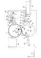
(i)版胴の内側にインキ供給手段を有するタイプの孔版印刷装置
孔版印刷装置の全体概略を示した図10において、版胴1は開孔部1bを有する多孔構造の円筒体を有し、この円筒体の外周にはメッシュスクリーンが巻着されている。この版胴1の外周部には、版胴1の軸線と平行に回転自在な爪を有するクランプ手段35が設けられている。このクランプ手段35は図示されない開閉装置により駆動力を伝達されて、所定位置にて開閉される。
【0060】
マスタ8は、版胴1の右側にある製版書き込み装置40の中にあるサーマルヘッド9により原稿の情報を基に穿孔された後、版胴1に向けて送り出され版胴1に巻装される。この巻装に際しては、先ず、クランプ手段35がマスタ8の一端を挾持し、次いで、マスタ8の他端側が版胴1の外周面に巻装されていく。
【0061】
ここで、製版書き込み装置40内の製版手段の構成及び製版動作について説明する。符号10はマスタ8をサーマルヘッド9に押しつけながら搬送するプラテンローラ、符号11はマスタ8を切断するためのカッタ、符号12はマスタ8の先端を版胴1のクランプ手段35へ案内するための給版ローラをそれぞれ示す。
この製版書き込み装置40において、図示を省略したスキャナーから送られてきた画像信号に基づいてサーマルヘッド9はマスタ8を穿孔し製版する。製版されたマスタ8は、所定の位置で開いて待機しているクランプ手段35にその先端を係止される。係止されると版胴1が矢印の向きに回転を始め、製版されたマスタ8を外周に巻き付けていく。マスタ8の送り量はプラテンローラ10を駆動するパルスモータ10aによってコントロールされ、一定量の送りが完了すれば、カッタ駆動モータ11aが偏芯カム11bを回転させてカッタ11を動かし、マスタ8を切断する。版胴1が製版済みのマスタ8を外周に巻き付け完了することで製版給版が完了する。
【0062】
版胴1の左側には、すでに版胴1に巻着されている使用済みマスタを剥離し、格納するための排版装置20がある。製版、給版が完了後、版胴1は図2に示されたモータ51等の駆動装置により時計回りの向きに回転させられる。版胴1の内部には、該版胴1と同方向に同期して回転するインキローラ2と、このインキローラ2の外周面と僅かに隙間を設けてドクターローラ3が配置されており、これらのローラによりインキ溜り50のインキ4をインキローラ2の外周面に供給する。
【0063】
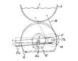
インキ4は軸パイプ5の穴より楔状空間のインキ溜り50に供給される。さらに、インキローラ2の外周面に供給されたインキは、版胴1の内周面とインキローラ2の外周面との間に設けられた僅かな隙間を介して版胴内周面に供給される。版胴1の下方には、圧胴14を支持する圧胴軸14aが、支点としての軸27aを中心に回動自在なアーム25aに支持されている。圧胴14はアーム25aの揺動に応じて版胴1に対して接離自在である。圧胴14はその径を版胴1の直径と略等しく形成され、版胴1との押圧位置が回転毎に同じになるような回転比で回転される。回転の向きは、図10で反時計回りの向きである。
【0064】
圧胴14は、版胴1上のクランプ手段35との衝突を避けるために、外周の一部を切り落した如き形状、つまり、外径部より内側に平坦部を設けた、所謂D型形状をしている。この平坦部には、印刷用の用紙30の先端を圧胴14に保持するくわえ爪29が軸29aに回動自在に設けてある。くわえ爪29は、図示されないカムにより所定のタイミングで開き、用紙30をくわえた後、閉じて圧胴14に用紙30を保持し、排紙爪15の位置に至ると再び開き、用紙30を解放して排紙搬送装置60に送り出す。圧胴14は用紙30の搬送ミス時の対処として、また、製版時に版胴1に圧胴14が圧接されないように、版胴1と同期して回転するカム53a、53b(図1、2参照)により所定のタイミングで版胴1より圧胴14を離すようにしている。
【0065】
搬送ミスがない場合には、再び、用紙30を保持した圧胴14がばね49a、49bにより版胴1の外周面に押圧されることとなる。搬送ミス等が発生した場合には、圧胴14は版胴1に押圧されないようにカム53a,53bが制御されることにより圧解除される。印刷後(インキ塗布後)の用紙30の先端部はくわえ爪29の解放により自由となり、圧胴14の外周近傍に設けられた排紙爪15により剥離されていき、排紙搬送装置60を介して排紙台21に送り出される。版胴1の右下方には、多数の用紙30を積載することのできるエレベータ方式の給紙台31と、圧胴14に用紙30を給送する給紙装置が設けられている。この給紙台31は図示されない駆動装置により、積載された用紙30の最上位が、常に呼出しローラ33に適切な範囲(用紙30が搬送可能な範囲)の押圧力で接触する状態を保持しつつ、昇降する。
【0066】
給紙装置は、回転自在に支持された給紙ローラ32と、呼出しローラ33を有している。これらのローラは無端ベルトにより連結されていて、同期して回転される。給紙ローラ32の下方には、印刷用紙30の重送を防止する分離ローラ34が圧接している。さらに、用紙搬送方向前方には回転自在に支持された一対のレジストローラ13と、用紙30をレジストローラニップ部に案内する一対のガイド板36が設けられている。
【0067】
給紙ローラ32は、版胴1と同期して回転する図示しないカムと、このカムに係合するカムフォロワを有する扇形ギヤ、ワンウェイクラッチが組み込まれた給紙ローラギヤにより、時計回りの向きに回転される。レジストローラ13も同様に、版胴1と同期して回転する図示しないカムと、このカムに係合するカムフォロワを有する扇形ギヤ、ワンウエイクラッチが組み込まれたレジストローラギヤなどにより、レジストローラ下方側が反時計回りの向きに回転される。レジストローラ13の用紙送り速度は版胴1の周速と同じに設定されている。
【0068】
用紙の搬送手順について説明する。
図10において、給紙ローラ32、呼出しローラ33の回転により給紙された用紙30は、給紙ローラ32と分離ローラ34部分で重送が防止され、最上位の1枚だけがレジストローラ13に送られる。やがて、用紙30の先端がレジストローラ13間のニップ部に衝突するが、さらに搬送を続けると上方に所定量のわん曲たるみ37が形成される。このわん曲たるみが形成された時点で、給紙ローラ32と呼出しローラ33の回転が停止される。
【0069】
その後、カムにより所定のタイミングでレジストローラ13が回転し、用紙30のわん曲たるみ37が消滅し、ワンウェイクラッチが組み込まれて用紙搬送方向に回転可能な給紙ローラ32と呼出しローラ33も、用紙30の搬送によって従動回転させられつつ、用紙30は圧胴14に向けて搬送される。このタイミングに合わせ、圧胴14中のくわえ爪29は開き、くわえ爪29は用紙30をくわえてから閉じ、圧胴14に用紙30が保持されたまま圧胴14は回転し、版胴1と圧胴14とのニップ部に用紙30が送り込まれる。
【0070】
前記したように、版胴1と圧胴14とのニップ部は、緊縮性のばね49a、49bの力により加圧されているので、圧胴14により用紙30は版胴1の外周面に押圧される。この押圧の際にインキローラ2により、版胴1の外周面に取り付けられているマスタ8の穿孔部を通過してきたインキ4が用紙30上に転写される。インキ4が転写された用紙30は、圧胴14が回転して排紙爪15の手前でくわえ爪29が開くことにより排紙爪15に乗り上げて剥離されつつ、排紙搬送装置60によって排紙台21上に搬送積載されて印刷を終了する。
【0071】
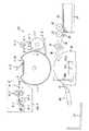
(ii)版胴の外側にインキ供給手段を有するタイプの孔版印刷装置
図11において、版胴1−1は外表面が無垢の開口部がない円筒部材であり、印刷工程実行時には矢印の向きに回転し、マスタを排出するときには矢印の向きと反対の向きに回転する。
【0072】
版胴1−1の表面には、一部に有底凹部1−1Bが形成されていて、この有底凹部1−1Bを除いた周面にマスタが巻き付けられるようになっている。有底凹部1−1Bは平坦面を備え、この平坦面にはマスタの先端を把持するためのクランパ1−1Cが配置されている。この把持されたマスタの先端以外の範囲は、後述するインキ供給手段であるインキ供給機構から供給されて版胴1−1の周面に付着しているインキの粘着力によって版胴周面に密着するようになっている。
【0073】
版胴1−1について矢印で示す回転の向きに沿って、図示するように、回転方向の上流側から製版書き込み装置40−1、インキ供給機構22、圧胴14がそれぞれ配置されている。なお、圧胴14及びこれに付帯する部材の構成、また、給紙手段としての呼出しローラ33、給紙台31、給紙ローラ32、レジストローラ13、分離ローラ34、ガイド板36等の構成、さらに、排紙爪15、排紙搬送装置60、排紙台21等については、前記図10に則して説明した構成と同じであるので、説明を省略する。
【0074】
製版装置40−1は、芯材に対してロール状に巻かれて順次繰り出し可能なマスタ8−1に対して原稿情報に応じた穿孔処理を行なうことで製版を実行するためのものであり、サーマルヘッド9−1、プラテンローラ10−1、搬送ローラ対12−1、裁断装置であるカッタ11−1及びマスタガイド7が備えられている。
【0075】
マスタ8−1は、1〜2μm程度の厚さを有するポリエステル等の熱可塑性樹脂フィルムに対して多孔質弾性体からなる多孔性支持体を貼り付けてラミネート構造としたものが用いられる。ロールから繰り出されたマスタ8−1は、サーマルヘッド9−1に対してプラテンローラ10−1によって押圧され、サーマルヘッド9−1の発熱素子が選択的に発熱させられることにより主走査方向及び副走査方向の領域で厚さ方向に貫通する孔が穿たれる。図示しない製版穿孔制御部からの駆動信号を用いた通電制御によりサーマルヘッド9−1の発熱素子は主走査方向で発熱位置が選択され発熱し、マスタ8−1の穿孔処理を行なう。
【0076】
プラテンローラ10−1は、図示しないステッピングモータ等を駆動源として備え、段階的な回転を行なうことによってマスタ8−1を副走査方向に給送する。プラテンローラ9−1の下流側には、搬送ローラ対12−1が配置されている。搬送ローラ対12−1はトルクリミッタを介して上記ステッピングモータに連動することができ、プラテンローラ10−1により設定されるマスタの搬送速度よりも僅かに速い搬送速度で送る。これにより、マスタ8−1は、プラテンローラ10−1と搬送ローラ対12−1との速度差によって弛みやしわ等の発生が抑止される。穿孔処理を終了したマスタ8−1は、カッタ11−1により必要長さに裁断され、版胴1−1の接線方向に給送されてクランパ1−1Cにより先端を把持固定される。
【0077】
インキ供給機構22について説明する。
インキ供給機構22は、版胴1−1の外周面から接離可能に設けられている。インキ供給機構22は、版胴1−1の外周面と当接するインキローラ2−1と、ブレード2−2と、インキローラ2−1との間に間隔をもって配置されたドクターローラ2−3とを主要部として構成されている。インキローラ2−1は、インキ供給管2−4の下方に位置する金属ローラであり、図示しない歯車やベルト等の駆動力伝達手段によって回転力が伝達され、版胴1−1の周速度と同期した速度で回転するようになっている。ドクターローラ2−3によって担持量を規制され、均一層状にインキを担持されたインキローラ2−1は、版胴1−1の外表面に巻装されているマスタ8−1の外側から接触してインキを供給する。
【0078】
インキローラ2−1とドクターローラ2−3との間の間隔によって設定されるインキローラ2−1上でのインキの担持量は、版胴1−1とマスタ8−1との対向面間の隙間及びマスタ8−1の穿孔部を含めた空間内に充填できる量に多少の余裕を見込んだ量に設定されている。上記空間内に充填される量は、1枚の印刷用の用紙に画像を印刷できる量に相当させてある。インキローラ2−1とドクターローラ2−3とで構成される楔状空間部はインキ溜り50−1であり、この部分には、インキ供給管2−4に形成されている吐出部から滴下するインキ4−1が溜まるようになっている。
【0079】
ブレード2−2は、マスタ8−1の外側から供給されたインキのうちでマスタ8−1の穿孔部以外(非画像部)に付着しているインキを除去するようになっている。この場合の穿孔部以外とは、主に孔版マスタ8−1の表面が該当しており、表面に付着しているインキが除去されると、これにより、インキローラ2−1から供給されるインキはマスタ8−1の穿孔部及び版胴1−1の外表面部とその面に対向するマスタ8−1の面とで構成される空間にのみ充填されることとなる。
【0080】
印刷に際して、製版されたマスタ8−1は製版書き込み装置40−1から繰り出され、サーマルヘッド9−1とプラテンローラ10−1とが当接している位置に達することで加熱溶融穿孔処理が実行され、穿孔が形成されたマスタ8−1がプラテンローラ10−1の回転量に基づいて版胴1−1に向けて給送され、先端がクランパ1−1Cに達した時点でクランパ1−1Cにより先端を把持されて固定される。
【0081】
版胴1−1は、マスタ8−1の先端を把持した時点から回転を始め、その周面にマスタ8−1が巻装され、所定量送られた後、カッタ11−1で裁断されて巻装が完了する。なお、マスタ8−1の先端把持に先立ち、版胴1−1に対してインキ供給機構22のインキローラ2−1によって均一膜厚でインキが塗布され、このインキをマスタ8−1の先端以外の領域の粘着に用いる。このように、版胴1−1の回転に伴い先端以外の領域がインキで塗布されて表面が粘着性を帯びるので、印刷中におけるマスタ8−1のずれが防止される。マスタの巻装が終わると版胴1−1の回転が停止し、次いで、印刷処理が実行される。
【0082】
印刷処理に際しては、版胴1−1の表面に位置するマスタ8−1にインキ供給機構22のインキローラ2−1が当接すると共に、インキ供給管2−4からインキが供給される。これにより、インキ溜り50−1に溜るインキは、ドクターローラ2−3によってインキローラ2−1の表面での担持量が規定され、マスタ8−1の表面から穿孔部を介して版胴1−1の表面とマスタ8−1の対向面との間の空間内にインキが押し込まれて供給される。
【0083】
インキローラ2−1を通過したマスタ8−1の表面には、インキローラ2−1から供給されたにも拘らず上記空間内に充填されなかったインキが表面に付着している。この付着しているインキは、ブレード2−2によって除去される。この除去されたインキは、インキローラ2−1とブレード2−2との対向位置にある隙間を通過してインキ溜り50−1に回収される。
【0084】
このようにしてマスタ8−1に対するインキの供給が行なわれると、給紙手段のレジストローラ13から繰り出された印刷用紙30がマスタの転写領域と整合し得る所定のタイミングをもって回転を開始した圧胴14のくわえ爪29(図11において図示省略)に向けて給送される。このとき、圧胴14は版胴1−1から離間している。給送された用紙30は圧胴14のくわえ爪29に先端部を把持されて圧胴14の周面に巻装される。
【0085】
アーム25a、25bの揺動によって版胴1−1とタイミングを合わせて圧胴14が版胴1−1に圧接すると、用紙30はマスタ8−1の表面に圧胴14により押圧される。用紙30は、圧胴14により押圧されると、マスタ8−1の多孔質支持体からなる多孔性支持体が圧縮変形して前記空間の体積が縮小されることから該空間内に充填されているインキがマスタ8−1の穿孔部から外側に向けて吐出される。これにより、用紙30にインキが転移し、画像の転写が行なわれる。
【0086】
一方、用紙30が圧胴14との対向位置を外れ始めることにより、圧胴14による押圧が解除されるので、マスタ8−1の多孔性支持体は元の厚さを有する形状に復帰し始める。この復帰に伴い、上記空間は負圧傾向となり、用紙30に過剰に付着しているインキを吸い戻す。インキが転写された用紙30は、圧胴14が回転して排紙爪15の手前でくわえ爪29が開くことにより排紙爪15に乗り上げて剥離されつつ、排紙搬送装置60によって排紙台21上に搬送積載されて印刷を終了する。
【0087】
【発明の効果】
請求項1に記載の発明では、接離手段により圧胴が位置変動するにも拘らず該圧胴を速度変動することなく定速回転させることができるので、従来技術で問題とされた、圧胴への用紙のくわえ込みのミスが発生するという問題をなくすることができる。
【0088】
請求項2記載の発明では、圧胴に対する動力の伝達手段としてオールダム軸継手を使用しており、オールダム軸継手は溝と角形突起とが互いに噛み合っているだけの継手であるので、メンテナンス時において該オールダム軸継手の部分を容易に分解し、組み立てることができ、圧胴の組み付け作業性を向上させることができる。また、オールダム軸継手では溝と角形突起との噛み合い位置が特定しやすいので、版胴と圧胴との位置合わせも容易である。
【0089】
請求項3記載の発明では、係止フックがガイドフランジからのスライダーの離脱を防止するので、圧胴脱着時の操作性を向上することができる。
【0090】
請求項4記載の発明では、嵌合規制手段は、視認性にすぐれるとともにスライダーとガイドフランジとの一義的な嵌合状態を定めるので、組み立て性の向上を図ることができる。
【図面の簡単な説明】
【図1】本発明にかかる孔版印刷装置における圧胴の支持状態および駆動系を説明した孔版印刷装置の要部断面図である。
【図2】本発明にかかる孔版印刷装置の版胴および圧胴の駆動系を説明した図である。
【図3】本発明にかかる伝達手段としてのオールダム軸継手の分解斜視図である。
【図4】本発明にかかる伝達手段としてのオールダム軸継手の変形例としてのアメリカン軸継手の分解斜視図である。
【図5】図1に示した孔版印刷装置において、版胴を分解するに際して部材の一部をスライドしたときの状態を説明した孔版印刷装置の断面図である。
【図6】アームと圧胴軸との、軸受を介しての係合関係の一例を説明した圧胴軸の一端側における当該係合部分の斜視図である。
【図7】アームと圧胴軸との、軸受を介しての係合関係の一例を説明した圧胴軸の他端側における当該係合部分の斜視図である。
【図8】アームと圧胴軸との、軸受を介しての係合関係の他の一例を説明した圧胴軸の一端側における当該係合部分の斜視図である。
【図9】アームと圧胴軸との、軸受を介しての係合関係の他の一例を説明した圧胴軸の他端側における当該係合部分の斜視図である。
【図10】本発明の実施に適する孔版印刷装置であって、版胴の内部にインキ供給手段を有するタイプのものの一例を説明した孔版印刷装置の概略構成図である。
【図11】本発明の実施に適する孔版印刷装置であって、版胴の外部にインキ供給手段を有するタイプのものの一例を説明した孔版印刷装置の概略構成図である。
【図12】従来技術にかかる孔版印刷装置における版胴および圧胴などの駆動系を説明した図である。
【図13】従来技術にかかる孔版印刷装置における圧胴の支持状態および駆動系を説明した孔版印刷装置の要部断面図である。
【図14】従来技術においてアームの揺動に連れて圧胴が速度変動することの理由を説明した圧胴の駆動系の概略構成図である。
【図15】従来技術においてアームの揺動に連れて圧胴が速度変動することの理由を説明した圧胴の駆動系の概略構成図である。
【図16】嵌合規制手段を説明したオールダム軸継手の斜視図である。
【図17】図16に対応した嵌合規制手段の説明図である。
【図18】嵌合規制手段の他の例を説明した図である。
【図19】係止フックの説明図である。
【符号の説明】
1、1−1 版胴
14 圧胴
43−1 (圧胴の駆動系としての)ベルト
46、47、50a (圧胴の駆動系としての)プーリ
48 (圧胴の駆動系としての)ベルト
50b (圧胴の駆動系としての)ギヤ
51 (圧胴の駆動系としての)モータ
80h、80h’ (嵌合規制手段としての)溝
81h、81h’ (嵌合規制手段としての)角形突起
81f−1、81f−2 係止フック
83 (伝達手段としての)オールダム軸継手
83−1(オールダム軸継手の変形例としての)アメリカン軸継手[0001]
BACKGROUND OF THE INVENTION
The present invention relates to a stencil printing apparatus.
[0002]
[Prior art]
In FIG. 12 for explaining the main part of the printing unit drive system of the conventional stencil printing apparatus, the
[0003]
As shown in FIG. 13, the
[0004]
A
[0005]
The
[0006]
The
[0007]
As described above, in a state where printing is performed, that is, in a state where a sheet exists between the
[0008]
Therefore, in order to control the contact / separation of the
[0009]
The hook levers 200a and 200b are provided in such a manner that they can be freely engaged and disengaged with respect to the respective distal ends of the
[0010]
The central portion of the
[0011]
Under the released state, the
[0012]
Since printing paper exists between the
[0013]
[Problems to be solved by the invention]
(1). As described above, the
[0014]
In FIG. 14, it is assumed that the
[0015]
On the contrary, when pressing the
[0016]
The
[0017]
(2). Transmission of the driving force to the
[0018]
In the present invention, the
[0019]
Another object of the present invention is to provide a stencil printing apparatus capable of improving the workability of assembling the impression cylinder during maintenance.
[0020]
[Means for Solving the Problems]
In order to achieve the above object, the present invention employs the following configuration.
[0021]
(1) A cylindrical plate cylinder that has an ink supply means and rotates with a perforated master mounted on the outer peripheral surface portion, and a printing sheet fed one by one from the paper supply means on the peripheral surface A cylindrical impression cylinder that is driven to rotate in the direction opposite to the rotation direction of the plate cylinder while pressing the sheet against the plate cylinder on the gripping and winding, and the absence of the sheet of the impression cylinder with respect to the plate cylinder In order to avoid contact in a state, a stencil printing apparatus having contact / separation means for moving the impression cylinder toward and away from the plate cylinder in accordance with the timing of feeding, the drive system of the impression cylinder is the Arranged on a stationary member that is not affected by the contact / separation operation, regardless of the position change of the impression cylinder by the contact / separation means, without changing the speed of the impression cylinder through the process of the contact / separation operation and before and after the contact / separation operation Smooth rotation of the impression cylinder according to the rotation state of the drive system And connecting the impression cylinder and the drive system with the transmission means transmits power in state (claim 1).
[0022]
(2) In the stencil printing apparatus according to (1), an Oldham shaft joint is used as the transmission means.
[0023]
(3) In the stencil printing apparatus according to (2), the Oldham shaft coupling has a slider and guide flanges on both sides thereof, and the slider is engaged with the guide flange on the drive system side of the impression cylinder. A stop hook is provided (claim 3).
[0024]
(4) In the stencil printing apparatus according to (2), the Oldham shaft coupling has a slider and guide flanges on both sides thereof, and the fitting restriction of both the slider and the guide flange on the impression cylinder side There is provided a fitting restricting means (claim 4).
[0025]
DETAILED DESCRIPTION OF THE INVENTION
Hereinafter, embodiments of the present invention will be described in detail with reference to the drawings.
In FIG. 1 and FIG. 2, the same members as those in FIG. 12 and FIG. 13 described as the prior art are denoted by the same reference numerals, description thereof is omitted, and different components are mainly described. In FIG. 2,
[0026]
The side plate 23b is provided with a gear 44-1 in a box-shaped cover 30-1. The gear 44-1 is fixed to the shaft 27b-1. One end side of the shaft 27b-1 is supported by a bearing 45-1 provided on the cover 30-1. The other end of the shaft 27b-1 is supported by a bearing 28-1 provided on the side plate 23b, and passes through the bearing 28-1 and protrudes inside the side plate 23b.
[0027]
An
[0028]
Thus, the shafts 27b-1 projecting inward from the side plate 23b and the shafts of the
[0029]
In this example, as a transmission means for transmitting the rotation of the shaft 27b-1 forming a part of the drive system of the
[0030]
As shown in FIGS. 1, 3, and 5, the
[0031]
As a modification of the Oldham shaft joint, there is an American shaft joint 83-1 shown in FIG. In the case of this American shaft joint, a guide flange 80-1 attached to the
[0032]
If the drive side shaft 27b-1 and the driven side
[0033]
Next, in the stencil printing apparatus using the
(A) Case in which the impression cylinder is moved in the axial direction and then moved in the direction perpendicular to the axis for disassembly.
This will be described with reference to FIGS. 1 and 5 to 7.
In FIG. 1, both
[0034]
The end face of the large diameter portion of the
[0035]
When disassembling the
[0036]
Here, as shown in FIG. 6, the upper portion of the hole 25b-H of the arm 25b fitted to the small diameter portion of the
[0037]
When the
[0038]
When the alignment mark is marked with a flat line or the like, the operator only confirms it visually, so it cannot be said that there is no possibility of misunderstanding. Therefore, if a three-dimensional fitting restriction means is provided on the
[0039]
In the example shown in FIGS. 16 and 17, the rectangular protrusion 81h formed on the
[0040]
A combination of the square protrusion 81h and the
[0041]
As the fitting restricting means, as shown in FIG. 18, a rectangular protrusion 81h ′ that forms a circular bulge at a position deviated from the center of the
[0042]
In this way, the fitting restricting means is not flat like a line-shaped alignment mark, but has a function as a three-dimensional mark, so that the visibility at the time of assembling the impression cylinder is remarkably improved, and visually In addition, since the fitting state is uniquely determined, the reliability is increased and the assemblability can be improved.
[0043]
When the
[0044]
In addition, since the free end side of the
[0045]
(B) Case where the impression cylinder is disassembled simply by moving in the direction perpendicular to the axis.
In the Oldham shaft joint 83, the grooves of the
[0046]
In this example, as means for releasing the restraint of the
[0047]
By adopting such a configuration, it is possible to disassemble the
[0048]
The Oldham shaft joint 83 in each of the cases (a) and (b) to be disassembled allows the
[0049]
Here, in the case of a normal Oldham shaft joint that is commercially available, the
[0050]
On the other hand, as a condition to which the present invention is applied, the
[0051]
This deviation appears as a phenomenon in which the operation amount of the arm 25b is insufficient with respect to the operation amount of the
[0052]
In order to eliminate such a problem, the
[0053]
On the other hand, the
[0054]
Therefore, as shown in FIG. 19, in order to prevent the
[0055]
The inner diameters of these locking hooks 81f-1 and 81f-2 are such that the
[0056]
In this way, the
[0057]
The shape of the square projection and the shape of the groove fitted to the square projection are stepped as shown in FIG. 17, and the Oldham shaft coupling is located at a position where the narrow portion of the square projection is below. If the rotation of the pressure cylinder is stopped and the impression cylinder is detached, the step portion functions to prevent dropping, so that the stop position does not depend on the position of the locking hook. Furthermore, as shown in FIG. 18, when the shape of the step portion is made to bulge in the intermediate portion, the step portion functions to prevent dropping at every rotational position of the Oldham shaft joint.
In the example shown in FIG. 19, two locking hooks are provided. However, three or more locking hooks may be provided as appropriate so that the rotation stop position of the Oldham shaft joint is not limited. If the rotation stop position of the joint is limited, at least one may be used as long as separation in the longitudinal direction of the shaft can be prevented.
[0058]
The present invention can also be applied to (i) a stencil printing apparatus having an ink supply means inside the plate cylinder, and (ii) a stencil printing apparatus having an ink supply means outside the plate cylinder. Even can be applied.
An outline of the printing process in each type will be described.
[0059]
(I) Stencil printing apparatus of the type having an ink supply means inside the plate cylinder
In FIG. 10 showing the overall outline of the stencil printing apparatus, the
[0060]
The
[0061]
Here, the configuration of the plate making means in the plate making writing device 40 and the plate making operation will be described.
In the plate making and writing apparatus 40, the thermal head 9 punches the
[0062]
On the left side of the
[0063]
The
[0064]
In order to avoid collision with the clamping means 35 on the
[0065]
When there is no conveyance mistake, the
[0066]
The sheet feeding device includes a
[0067]
The
[0068]
The paper transport procedure will be described.
In FIG. 10, the
[0069]
Thereafter, the
[0070]
As described above, the nip portion between the
[0071]
(Ii) A stencil printing apparatus of the type having ink supply means outside the plate cylinder
In FIG. 11, the plate cylinder 1-1 is a cylindrical member whose outer surface has no solid opening, and rotates in the direction of the arrow when executing the printing process, and rotates in the direction opposite to the direction of the arrow when discharging the master. .
[0072]
A bottomed recess 1-1B is partially formed on the surface of the plate cylinder 1-1, and a master is wound around a peripheral surface excluding the bottomed recess 1-1B. The bottomed recess 1-1B has a flat surface, and a clamper 1-1C for holding the tip of the master is disposed on the flat surface. The range other than the tip of the gripped master is in close contact with the peripheral surface of the plate cylinder by the adhesive force of the ink supplied from the ink supply mechanism, which will be described later, and attached to the peripheral surface of the plate cylinder 1-1. It is supposed to be.
[0073]
As shown in the drawing, the plate making / writing device 40-1, the
[0074]
The plate making apparatus 40-1 is for performing plate making by performing a punching process according to document information on a master 8-1 that is wound around a core material in a roll shape and can be sequentially fed. A thermal head 9-1, a platen roller 10-1, a conveying roller pair 12-1, a cutter 11-1 as a cutting device, and a
[0075]
As the master 8-1, a laminate structure in which a porous support made of a porous elastic body is attached to a thermoplastic resin film such as polyester having a thickness of about 1 to 2 μm is used. The master 8-1 paid out from the roll is pressed against the thermal head 9-1 by the platen roller 10-1, and the heat generating elements of the thermal head 9-1 are selectively heated to thereby generate heat in the main scanning direction and the auxiliary direction. A hole penetrating in the thickness direction is formed in a region in the scanning direction. The heating element of the thermal head 9-1 is selected in the main scanning direction to generate heat by energization control using a drive signal from a plate making punch control unit (not shown), and the master 8-1 is punched.
[0076]
The platen roller 10-1 includes a stepping motor or the like (not shown) as a drive source, and feeds the master 8-1 in the sub-scanning direction by performing stepwise rotation. A conveying roller pair 12-1 is disposed on the downstream side of the platen roller 9-1. The conveyance roller pair 12-1 can be linked to the stepping motor via a torque limiter, and is fed at a conveyance speed slightly faster than the master conveyance speed set by the platen roller 10-1. As a result, the master 8-1 is prevented from slackening or wrinkling due to the speed difference between the platen roller 10-1 and the conveying roller pair 12-1. The master 8-1 that has completed the punching process is cut to a required length by the cutter 11-1, fed in the tangential direction of the plate cylinder 1-1, and the tip is held and fixed by the clamper 1-1C.
[0077]
The
The
[0078]
The amount of ink carried on the ink roller 2-1 set by the distance between the ink roller 2-1 and the doctor roller 2-3 is between the opposing surfaces of the plate cylinder 1-1 and the master 8-1. The amount that can be filled in the space including the gap and the perforated portion of the master 8-1 is set to an amount that allows some margin. The amount filled in the space corresponds to the amount by which an image can be printed on one sheet of printing paper. The wedge-shaped space portion composed of the ink roller 2-1 and the doctor roller 2-3 is an ink reservoir 50-1, and ink dropped from the discharge portion formed in the ink supply tube 2-4 is provided in this portion. 4-1.
[0079]
The blade 2-2 removes ink adhering to a portion other than the perforated portion (non-image portion) of the master 8-1 from the ink supplied from the outside of the master 8-1. In this case, the surface other than the perforated part mainly corresponds to the surface of the stencil master 8-1, and when the ink adhering to the surface is removed, the ink supplied from the ink roller 2-1 is thereby removed. Is filled only in the space constituted by the perforated portion of the master 8-1 and the outer surface portion of the plate cylinder 1-1 and the surface of the master 8-1 facing the surface.
[0080]
At the time of printing, the master 8-1 that has been subjected to plate making is fed out from the plate making writing device 40-1, and reaches the position where the thermal head 9-1 and the platen roller 10-1 are in contact with each other, thereby performing the heat melting perforation processing. The master 8-1 in which the perforations are formed is fed toward the plate cylinder 1-1 based on the rotation amount of the platen roller 10-1, and when the tip reaches the clamper 1-1C, the clamper 1-1C The tip is gripped and fixed.
[0081]
The plate cylinder 1-1 starts rotating from the time when the front end of the master 8-1 is gripped, and the master 8-1 is wound around the peripheral surface and fed by a predetermined amount, and then cut by the cutter 11-1. Winding is complete. Prior to gripping the leading edge of the master 8-1, ink is applied to the plate cylinder 1-1 with a uniform film thickness by the ink roller 2-1 of the
[0082]
In the printing process, the ink roller 2-1 of the
[0083]
On the surface of the master 8-1 that has passed through the ink roller 2-1, ink that has been supplied from the ink roller 2-1 but has not been filled in the space adheres to the surface. The adhered ink is removed by the blade 2-2. The removed ink passes through a gap at a position where the ink roller 2-1 and the blade 2-2 face each other and is collected in the ink reservoir 50-1.
[0084]
When ink is supplied to the master 8-1 in this way, the impression cylinder that has started rotating at a predetermined timing at which the
[0085]
When the
[0086]
On the other hand, when the
[0087]
【The invention's effect】
In the first aspect of the present invention, the pressure drum can be rotated at a constant speed without changing the speed despite the position change of the pressure drum by the contact / separation means. It is possible to eliminate the problem that an error in holding the paper into the cylinder occurs.
[0088]
In the second aspect of the invention, an Oldham shaft joint is used as a means for transmitting power to the impression cylinder, and the Oldham shaft joint is a joint in which the groove and the square projection are meshed with each other. The part of the Oldham shaft joint can be easily disassembled and assembled, and the assembling workability of the impression cylinder can be improved. Further, in the Oldham shaft coupling, the meshing position between the groove and the square protrusion can be easily specified, so that the plate cylinder and the impression cylinder can be easily aligned.
[0089]
In the invention described in claim 3, since the locking hook prevents the slider from being detached from the guide flange, the operability at the time of removing and attaching the impression cylinder can be improved.
[0090]
In the invention according to
[Brief description of the drawings]
FIG. 1 is a cross-sectional view of an essential part of a stencil printing apparatus, illustrating a support state of a pressure drum and a drive system in the stencil printing apparatus according to the present invention.
FIG. 2 is a diagram illustrating a drive system for a plate cylinder and an impression cylinder of the stencil printing apparatus according to the present invention.
FIG. 3 is an exploded perspective view of an Oldham shaft coupling as transmission means according to the present invention.
FIG. 4 is an exploded perspective view of an American shaft joint as a modified example of an Oldham shaft joint as a transmission means according to the present invention.
5 is a cross-sectional view of the stencil printing apparatus illustrating a state in which a part of the member is slid when disassembling the plate cylinder in the stencil printing apparatus shown in FIG.
FIG. 6 is a perspective view of the engaging portion on one end side of the impression cylinder shaft, illustrating an example of the engagement relationship between the arm and the impression cylinder shaft via a bearing.
FIG. 7 is a perspective view of the engagement portion on the other end side of the impression cylinder shaft, illustrating an example of the engagement relationship between the arm and the impression cylinder shaft via a bearing.
FIG. 8 is a perspective view of the engaging portion on one end side of the impression cylinder shaft, illustrating another example of the engagement relationship between the arm and the impression cylinder shaft via a bearing.
FIG. 9 is a perspective view of the engagement portion on the other end side of the impression cylinder shaft, illustrating another example of the engagement relationship between the arm and the impression cylinder shaft via a bearing.
FIG. 10 is a schematic configuration diagram of a stencil printing apparatus, which is an example of a stencil printing apparatus suitable for carrying out the present invention and has an ink supply means inside a plate cylinder.
FIG. 11 is a schematic configuration diagram of a stencil printing apparatus, which is an example of a stencil printing apparatus suitable for carrying out the present invention and has an ink supply means outside the plate cylinder.
FIG. 12 is a diagram illustrating drive systems such as a plate cylinder and an impression cylinder in a stencil printing apparatus according to a conventional technique.
FIG. 13 is a cross-sectional view of the main part of the stencil printing apparatus, explaining the support state of the impression cylinder and the drive system in the stencil printing apparatus according to the prior art.
FIG. 14 is a schematic configuration diagram of a driving system for an impression cylinder, explaining the reason why the impression cylinder fluctuates in speed as the arm swings in the prior art.
FIG. 15 is a schematic configuration diagram of a driving system for an impression cylinder that explains the reason why the impression cylinder fluctuates in speed as the arm swings in the prior art.
FIG. 16 is a perspective view of an Oldham shaft coupling explaining fitting restriction means.
FIG. 17 is an explanatory diagram of the fitting restricting means corresponding to FIG. 16;
FIG. 18 is a diagram illustrating another example of the fitting restricting means.
FIG. 19 is an explanatory diagram of a locking hook.
[Explanation of symbols]
1, 1-1 plate cylinder
14 impression cylinder
43-1 Belt (as impression cylinder drive system)
46, 47, 50a Pulley (as drive system for impression cylinder)
48 Belt (as impression cylinder drive system)
50b Gear (as drive system for impression cylinder)
51 Motor (as impression cylinder drive system)
80h, 80h 'grooves (as fitting restriction means)
81h, 81h 'square projection (as fitting restricting means)
81f-1, 81f-2 Locking hook
83 Oldham shaft coupling (as transmission means)
83-1 American Shaft Coupling (as a variation of Oldham Shaft Coupling)
Claims (4)
Translated fromJapanese給紙手段から1枚ずつ給紙される印刷用の用紙を周面に把持巻着の上、この用紙を前記版胴に押圧しつつ前記版胴の回転方向と反対の向きに回転駆動される筒状の圧胴と、
前記版胴に対する前記圧胴の前記用紙のない状態での接触を避けるために前記版胴に対して前記圧胴を前記給紙のタイミングに合わせて接離動作させる接離手段と、
を有する孔版印刷装置において、
前記圧胴の駆動系を前記接離動作に影響されない不動部材に配置し、前記接離手段による前記圧胴の位置変動に拘らず前記接離動作の過程および前記接離動作の前後を通じて前記圧胴に速度変動を与えることなく前記圧胴を前記駆動系の回転状態に従うなめらな回転状態で動力伝達する伝達手段をもって前記駆動系と前記圧胴とを連結したことを特徴とする孔版印刷装置。A cylindrical plate cylinder that has ink supply means and rotates in a state in which a perforated master is mounted on the outer peripheral surface portion;
A printing sheet fed one by one from the sheet feeding means is gripped and wound on the peripheral surface, and is rotated and driven in a direction opposite to the rotation direction of the plate cylinder while pressing the sheet against the plate cylinder. A cylindrical impression cylinder;
Contact / separation means for moving the impression cylinder to / from the plate cylinder in accordance with the sheet feeding timing in order to avoid contact of the impression cylinder with the plate cylinder without the paper;
In a stencil printing apparatus having
The drive system of the impression cylinder is disposed on a stationary member that is not affected by the contact / separation operation, and the pressure is applied through the process of the contact / separation operation and before and after the contact / separation operation regardless of the position fluctuation of the impression cylinder by the contact / separation means. A stencil printing apparatus characterized in that the drive system and the impression cylinder are connected with a transmission means for transmitting the power of the impression cylinder in a smooth rotation state according to the rotation state of the drive system without giving a speed fluctuation to the cylinder. .
Priority Applications (2)
| Application Number | Priority Date | Filing Date | Title |
|---|---|---|---|
| JP30252397AJP3825155B2 (en) | 1997-01-16 | 1997-11-05 | Stencil printing machine |
| US09/000,970US6019036A (en) | 1997-01-16 | 1997-12-30 | Stencil printer |
Applications Claiming Priority (3)
| Application Number | Priority Date | Filing Date | Title |
|---|---|---|---|
| JP9-5230 | 1997-01-16 | ||
| JP523097 | 1997-01-16 | ||
| JP30252397AJP3825155B2 (en) | 1997-01-16 | 1997-11-05 | Stencil printing machine |
Publications (2)
| Publication Number | Publication Date |
|---|---|
| JPH10258566A JPH10258566A (en) | 1998-09-29 |
| JP3825155B2true JP3825155B2 (en) | 2006-09-20 |
Family
ID=26339141
Family Applications (1)
| Application Number | Title | Priority Date | Filing Date |
|---|---|---|---|
| JP30252397AExpired - LifetimeJP3825155B2 (en) | 1997-01-16 | 1997-11-05 | Stencil printing machine |
Country Status (2)
| Country | Link |
|---|---|
| US (1) | US6019036A (en) |
| JP (1) | JP3825155B2 (en) |
Families Citing this family (9)
| Publication number | Priority date | Publication date | Assignee | Title |
|---|---|---|---|---|
| EP1000737B1 (en)* | 1998-11-06 | 2002-03-13 | Fischer & Krecke Gmbh & Co. | Printing machine |
| JP4410352B2 (en) | 1999-04-28 | 2010-02-03 | 東北リコー株式会社 | Stencil printing machine |
| JP4592900B2 (en)* | 2000-09-08 | 2010-12-08 | 東北リコー株式会社 | Printing device |
| JP4608066B2 (en)* | 2000-09-12 | 2011-01-05 | 東北リコー株式会社 | Printing device |
| JP2003184903A (en)* | 2001-12-18 | 2003-07-03 | Yaskawa Electric Corp | Oldham coupling |
| US20060024114A1 (en)* | 2004-07-29 | 2006-02-02 | Zih Corp. | Printer assembly and method of using the same |
| JP4758247B2 (en)* | 2006-02-20 | 2011-08-24 | 株式会社東芝 | Drive transmission mechanism and image forming apparatus having the same |
| JP5220284B2 (en)* | 2006-05-15 | 2013-06-26 | 株式会社ハーモニック・ドライブ・システムズ | Film winding roll rotation mechanism |
| JP2009073032A (en)* | 2007-09-20 | 2009-04-09 | Sakurai Graphic Syst:Kk | Cylinder screen printing machine and its printing method |
Family Cites Families (7)
| Publication number | Priority date | Publication date | Assignee | Title |
|---|---|---|---|---|
| US3630146A (en)* | 1970-02-04 | 1971-12-28 | S & S Corrugated Paper Mach | Interruptable inking cylinder and scraper blade forming open ended fountain trough |
| US4712447A (en)* | 1986-04-24 | 1987-12-15 | Sms Concast Inc. | Oscillator for a continuous casting mold |
| JPH02238469A (en)* | 1989-03-10 | 1990-09-20 | Canon Inc | Image forming device |
| ES2050645T3 (en)* | 1990-10-01 | 1994-11-01 | Copeland Corp | OLDHAM COUPLING FOR SNAIL COMPRESSOR. |
| US5376954A (en)* | 1991-08-23 | 1994-12-27 | Eastman Kodak Company | Vacuum imaging drum with an axial flat in the periphery thereof |
| JPH091914A (en)* | 1995-06-21 | 1997-01-07 | Tohoku Ricoh Co Ltd | Method for producing paper cylinder, and means for supporting paper cylinder |
| JPH09216448A (en)* | 1996-02-13 | 1997-08-19 | Tohoku Ricoh Co Ltd | Stencil printing device |
- 1997
- 1997-11-05JPJP30252397Apatent/JP3825155B2/ennot_activeExpired - Lifetime
- 1997-12-30USUS09/000,970patent/US6019036A/ennot_activeExpired - Lifetime
Also Published As
| Publication number | Publication date |
|---|---|
| US6019036A (en) | 2000-02-01 |
| JPH10258566A (en) | 1998-09-29 |
Similar Documents
| Publication | Publication Date | Title |
|---|---|---|
| JPH0262451B2 (en) | ||
| JP3825155B2 (en) | Stencil printing machine | |
| KR100244166B1 (en) | Stencil and stencil perforating device | |
| US6374730B1 (en) | Stencil printer for duplex printing | |
| EP1170234B1 (en) | Paper feed unit | |
| JPH07237782A (en) | Stencil printer | |
| US5535671A (en) | Stencil duplicating machine applying uniform tension to a stencil | |
| US5472287A (en) | Printer with validation paper feeding mechanism | |
| JP4388111B2 (en) | Image forming apparatus | |
| JPH11151852A (en) | Double cylinder printing device | |
| JP2008049677A (en) | Printer device | |
| JPH0558481A (en) | Paper feed device for image forming device | |
| JPH09169154A (en) | Screen printing machine | |
| JP3648165B2 (en) | Paper feed mechanism of image forming apparatus | |
| JP3556693B2 (en) | Printer | |
| US5513564A (en) | Stencil duplicating machine | |
| JP4598370B2 (en) | Plate removal device and printing device | |
| JP4312283B2 (en) | Stencil printing machine | |
| JP2002326405A (en) | Mechanism for releasing platen roller of printer | |
| JPH0218023Y2 (en) | ||
| JP2870661B2 (en) | Stencil printing machine | |
| JP2560707Y2 (en) | Paper feed clutch device | |
| JP2515173Y2 (en) | Image forming device | |
| JP4454869B2 (en) | Sheet feeding device | |
| JP3453733B2 (en) | Stencil printing machine |
Legal Events
| Date | Code | Title | Description |
|---|---|---|---|
| A621 | Written request for application examination | Free format text:JAPANESE INTERMEDIATE CODE: A621 Effective date:20041027 | |
| A977 | Report on retrieval | Free format text:JAPANESE INTERMEDIATE CODE: A971007 Effective date:20060612 | |
| TRDD | Decision of grant or rejection written | ||
| A01 | Written decision to grant a patent or to grant a registration (utility model) | Free format text:JAPANESE INTERMEDIATE CODE: A01 Effective date:20060620 | |
| A61 | First payment of annual fees (during grant procedure) | Free format text:JAPANESE INTERMEDIATE CODE: A61 Effective date:20060629 | |
| R150 | Certificate of patent or registration of utility model | Free format text:JAPANESE INTERMEDIATE CODE: R150 | |
| FPAY | Renewal fee payment (event date is renewal date of database) | Free format text:PAYMENT UNTIL: 20090707 Year of fee payment:3 | |
| FPAY | Renewal fee payment (event date is renewal date of database) | Free format text:PAYMENT UNTIL: 20120707 Year of fee payment:6 | |
| FPAY | Renewal fee payment (event date is renewal date of database) | Free format text:PAYMENT UNTIL: 20120707 Year of fee payment:6 | |
| FPAY | Renewal fee payment (event date is renewal date of database) | Free format text:PAYMENT UNTIL: 20150707 Year of fee payment:9 | |
| S111 | Request for change of ownership or part of ownership | Free format text:JAPANESE INTERMEDIATE CODE: R313113 | |
| FPAY | Renewal fee payment (event date is renewal date of database) | Free format text:PAYMENT UNTIL: 20150707 Year of fee payment:9 | |
| R350 | Written notification of registration of transfer | Free format text:JAPANESE INTERMEDIATE CODE: R350 | |
| EXPY | Cancellation because of completion of term |