JP3824343B2 - Semiconductor device - Google Patents
Semiconductor deviceDownload PDFInfo
- Publication number
- JP3824343B2 JP3824343B2JP07745996AJP7745996AJP3824343B2JP 3824343 B2JP3824343 B2JP 3824343B2JP 07745996 AJP07745996 AJP 07745996AJP 7745996 AJP7745996 AJP 7745996AJP 3824343 B2JP3824343 B2JP 3824343B2
- Authority
- JP
- Japan
- Prior art keywords
- nmos
- region
- semiconductor device
- sram cell
- pmos
- Prior art date
- Legal status (The legal status is an assumption and is not a legal conclusion. Google has not performed a legal analysis and makes no representation as to the accuracy of the status listed.)
- Expired - Lifetime
Links
Images


Classifications
- H—ELECTRICITY
- H10—SEMICONDUCTOR DEVICES; ELECTRIC SOLID-STATE DEVICES NOT OTHERWISE PROVIDED FOR
- H10B—ELECTRONIC MEMORY DEVICES
- H10B10/00—Static random access memory [SRAM] devices
- H10B10/12—Static random access memory [SRAM] devices comprising a MOSFET load element
- Y—GENERAL TAGGING OF NEW TECHNOLOGICAL DEVELOPMENTS; GENERAL TAGGING OF CROSS-SECTIONAL TECHNOLOGIES SPANNING OVER SEVERAL SECTIONS OF THE IPC; TECHNICAL SUBJECTS COVERED BY FORMER USPC CROSS-REFERENCE ART COLLECTIONS [XRACs] AND DIGESTS
- Y10—TECHNICAL SUBJECTS COVERED BY FORMER USPC
- Y10S—TECHNICAL SUBJECTS COVERED BY FORMER USPC CROSS-REFERENCE ART COLLECTIONS [XRACs] AND DIGESTS
- Y10S257/00—Active solid-state devices, e.g. transistors, solid-state diodes
- Y10S257/903—FET configuration adapted for use as static memory cell
- Y10S257/904—FET configuration adapted for use as static memory cell with passive components,, e.g. polysilicon resistors
Landscapes
- Semiconductor Memories (AREA)
Description
Translated fromJapanese【0001】
【発明の属する技術分野】
本発明は、CMOS型SRAMセルを備えた半導体装置に関する。
【0002】
【従来の技術】
この種のSRAMは、メモリセルがDRAMのような電荷保持型ではなくフリップフロップによる電流駆動型であるので、高速アクセスが可能であり、キャッシュメモリとして用いられているが、マイクロプロセッサの高速化に伴い、より高速化が要求されている。
【0003】
図10は、従来のSRAMセル1のパターン図である。図11(A)は、図10のレイアウトパターンに対応した回路図であり、図11(B)はこの回路の接続を分かり易くした一般的な回路図である。
SRAMセル1は、pMOS領域2とnMOS領域3との間に素子分離領域4が形成され、素子分離領域4に平行にワード線WL、基準電位供給線VSS及び電源電位供給線VCCが配置されている。中心線のみで示す一対のビット線BL及び*BLは、ワード線WLと直角な方向に沿って配置されている。pMOSトランジスタQP1とnMOSトランジスタQN1とでCMOSインバータが形成され、pMOSトランジスタQP2とnMOSトランジスタQN2とでもう1つのCMOSインバータが形成され、これらCMOSインバータがクロス接続されてフリップフロップが形成されている。
【0004】
メタル配線S1〜S4及び電源電位供給線VCCはメタル配線第1層であり、基準電位供給線VSSはメタル配線第2層であり、ビット線BL及び*BLはメタル配線第3層である。
ポリシリコン配線G1は、pMOSトランジスタQP1及びnMOSトランジスタQN1のゲートを含み、かつ、その一端部がコンタクトホールを通ってpMOSトランジスタQP2のp型半導体領域P2dに接続されている。ポリシリコン配線G2は、pMOSトランジスタQP2及びnMOSトランジスタQN2のゲートを含み、かつ、その一端部がコンタクトホールを通ってnMOSトランジスタQN1のn型半導体領域N1dに接続されている。pMOSトランジスタQP1のp型半導体領域P1dとnMOSトランジスタQN1のn型半導体領域N1dとは、コンタクトホールを通ってメタル配線S1で接続され、pMOSトランジスタQP2のp型半導体領域P2dとnMOSトランジスタQN2のn型半導体領域N2dとは、コンタクロホールを通ってメタル配線S2で接続さている。また、nMOSトランジスタQN1のn型半導体領域N1sは、コンタクトホールを通りメタル配線S3で基準電位供給線VSSに接続され、nMOSトランジスタQN2のn型半導体領域N2sは、コンタクトホールを通りメタル配線S4で基準電位供給線VSSに接続されている。
【0005】
SRAMセル1に書き込まれたデータを読み出す場合には、ビット線BL及び*BLが所定電位にプリチャージされ(又はプリチャージされずに)、次にワード線WLが高レベルにされてnMOSトランジスタQN3及びQN4がオンにされる。これにより、ビット線BLとビット線*BLとの間に電位差が生じ、誤動作防止のためこれが所定値以上になった後に、不図示のセンスアンプで増幅され、データバスを介して外部に取り出される。
【0006】
【発明が解決しようとする課題】
従来のSRAMセル1は、pMOS領域2とnMOS領域3の間に素子分離領域4が形成され、素子分離領域4と直角な方向に沿ってビット線BL及び*BLが配置されているので、SRAMセルアレイにおいてはビット線BL及び*BLが長くなり、その容量及び抵抗が大きくなるため、データ読み出し速度の向上が制限される。データの書き込み速度についても同様である。
【0007】
本発明の目的は、このような問題点に鑑み、アクセスを高速化することが可能なCMOS型SRAMセルを備えた半導体装置を提供するとにある。
【0009】
【課題を解決するための手段及びその作用効果】
本発明の半導体装置では、
第1及び第3のnMOSトランジスタを有する第1のnMOS領域と、
第2及び第4のnMOSトランジスタを有する第2のnMOS領域と、
前記第1のnMOS領域と前記第2のnMOS領域の間に配置され、第1及び第2のpMOSトランジスタを有するpMOS領域と、
前記第1のnMOS領域と前記pMOS領域の間、及び前記第2のnMOS領域と前記pMOS領域の間に配置された素子分離領域と、
第1及び第2のビット線と、
ワード線と、
を有し、
前記第1及び第2のnMOSトランジスタと前記第1及び第2のpMOSトランジスタとがデータを格納するためのフリップフロップを構成し、
前記第3のnMOSトランジスタが前記第1のビット線と前記フリップフロップの間を接続する第1のトランスファーゲートを構成し、
前記第4のnMOSトランジスタが前記第2のビット線と前記フリップフロップの間を接続する第2のトランスファーゲートを構成し、
前記第3及び第4のnMOSトランジスタのゲートが前記ワード線に接続された、
SRAMセルを備えた半導体装置であって、
前記第1のnMOS領域、前記pMOS領域、及び前記第2のnMOS領域は第1の方向に並べて配置され
前記ワード線は前記第1の方向に延在し、
前記第1及び第2のビット線は前記第1の方向に対して垂直な第2の方向に延在し、
前記第1のnMOSトランジスタのゲートと前記第1のpMOSトランジスタのゲートは前記第1の方向に延在する第1のポリシリコン配線により構成され、
前記第2のnMOSトランジスタのゲートと前記第2のpMOSトランジスタのゲートは前記第1の方向に延在する第2のポリシリコン配線により構成され、
前記第3のnMOSトランジスタのゲートは前記第1の方向に延在する第3のポリシリコン配線により構成され、
前記第4のnMOSトランジスタのゲートは前記第1の方向に延在する第4のポリシリコン配線により構成され、
前記第1乃至第4のポリシリコン配線が、前記第1のポリシリコン配線及び前記第4のポリシリコン配線からなる第1の配線群と、前記第2のポリシリコン配線及び前記第3のポリシリコン配線からなる第2の配線群とから構成され、
前記第1の配線群と前記第2の配線群が前記第2の方向に並べて配置され、
前記第1のポリシリコン配線は前記第2のpMOSトランジスタのドレインとコンタクトホールを介して接続され、
前記第2のポリシリコン配線は前記第1のpMOSトランジスタのドレインとコンタクトホールを介して接続されている。
【0010】
本発明によれば、上記特徴により、前記第1の方向に垂直な第2の方向のセル幅が従来よりも狭くなり、これにより、第2の方向に延在するビット線の単位セル当たりの長さを従来よりも短くすることができるので、CMOS型SRAMセルのアクセス速度を従来よりも向上させることが可能となるという効果を奏する。また、ポリシリコンによる配線が効率的に行われるという効果を奏する。
本発明の第1態様では、上記第1nMOSトランジスタ、第4nMOSトランジスタ及び第1pMOSトランジスタがそれぞれ上記第1領域、第2領域及び第3領域の上記第1の方向(長手方向)と略直角な方向の一端側に配置され、
上記第3nMOSトランジスタ、第2nMOSトランジスタ及び第2pMOSトランジスタがそれぞれ該第1領域、第2領域及び第3領域の該長手方向と略直角な方向の他端側に配置されている。
【0011】
この第1態様によれば、第1nMOSトランジスタ及び第1pMOSトランジスタのゲートを含む配線が略直線になり、第2nMOSトランジスタ及び第2pMOSトランジスタのゲートを含む配線が略直線になるので、CMOS型SRAMセルの占有面積を狭くすることができるという効果を奏する。
本発明の第2態様では、上記第1nMOSトランジスタと上記第3nMOSトランジスタとが上記長手方向と略直角な方向に並置され、
該第1nMOSトランジスタの一方のn型半導体領域と該3nMOSトランジスタの一方のn型半導体領域とが共通領域であり、
上記第2nMOSトランジスタと上記第4nMOSトランジスタとが該長手方向と略直角な方向に並置され、
該第2nMOSトランジスタの一方のn型半導体領域と該4nMOSトランジスタの一方のn型半導体領域とが共通領域である。
【0012】
この第2態様によれば、上記第1領域及び第2領域がコンパクトになるので、CMOS型SRAMセルの占有面積を狭くすることができるという効果を奏する。
本発明の第3態様では、上記第1pMOSトランジスタが上記第3領域内の上記第1領域側に配置され、
上記第2pMOSトランジスタが該第3領域内の上記第2領域側に配置されている。
【0013】
この第3態様によれば、結合関係がより大きいトランジスタ間が対向する位置に存在するので、CMOS型SRAMセル内での素子間配線長が短くなり、CMOS型SRAMセルの占有面積を狭くすることができるという効果を奏する。
【0014】
本発明の第4態様では、上記CMOS型SRAMセルは矩形である。
【0015】
本発明のCMOS型SRAMセルは矩形に限定されないが、矩形はビット線を短くするのに有利であるので、第4態様によれば、ビット線をより短くすることができるという効果を奏する。
本発明の第5態様では、上記第3領域の上方に上記長手方向と略直角な方向に沿って上記電源電位供給線が配置され、
上記矩形の長手方向に対向する辺の各々に沿って上記基準電位供給線が配置されている。
【0016】
この第5態様によれば、電源配線がワード線と直角な方向に沿って配置されているので、SRAMにおいて1つのワード線を選択した場合に、このワード線に沿った各SRAMセルについて一対の電源配線から電圧が供給され、電源配線幅を広くしたのと同じ効果が得られ、電源電圧の変動が従来よりも低減されてノイズ耐性が向上するという効果を奏する。
【0017】
本発明の第6態様では、上記第1〜4nMOSトランジスタ並びに上記第1及び第2pMOSトランジスタは、上記矩形の中央点について略点対称に配置されている。
この第7態様によれば、SRAM製造において、該対称性により露光パターンの処理が簡単になるという効果を奏する。また、第1及び第2のCMOSインバータの形が同じになるので、動作が安定する。
【0018】
本発明の第7態様は、上記いずれかの態様のCMOS型SRAMセルが格子状に配置されたメモリセルアレイと、
該メモリセルアレイに対しデータの書き込み及び読み出しを行うための周辺回路と、
を有する半導体装置である。
【0019】
本発明の第8態様では、上記第6態様のCMOS型SRAMセルを有し、
該CMOS型SRAMセルは、上記矩形の長手方向の一辺を共通にして配置したときに該一辺について互いに線対称な第1形と第2形とが在り、
上記メモリセルアレイは、該第1形のCMOS型SRAMセルと該第2形のCMOS型SRAMセルとが該長手方向及び該長手方向と直角な方向について交互に配置され、
該矩形の該長手方向にワード線が配置され、
該第1形のCMOS型SRAMセルの上記第3nMOSトランジスタのゲートがメタル配線を介して該ワード線に接続され、
該第2形のCMOS型SRAMセルの上記第4nMOSトランジスタのゲートが隣の該第1形の第3nMOSトランジスタのゲートと連続した配線になっており、
該第1形のCMOS型SRAMセルの上記第4nMOSトランジスタのゲートがメタル配線を介して該ワード線に接続され、
該第2形のCMOS型SRAMセルの上記第3nMOSトランジスタのゲートが隣の該第1形の第4nMOSトランジスタのゲートと連続した配線になっている。
【0020】
この第8態様によれば、上記線対称性によりビット線方向に隣り合うCMOS型SRAMセルの一方の空き領域を他方のワード線接続領域として有効利用することができるので、CMOS型SRAMセルアレイの高集積化が可能となるという効果を奏する。
本発明の第9態様では、上記CMOS型SRAMセルは、上記ビット線に平行なデータ線が配置され、
該ビット線の方向に連続して配置された複数の該CMOS型SRAMセル毎に該データ線が該ビット線に接続され、
該データ線がCMOS型SRAMセルブロック間に配置されたデータバスに接続されている。
【0021】
ビット線は各SRAMセルで転送ゲートに接続されているので負荷が比較的大きいが、該データ線にはこのような負荷がない。
この第9態様では、該ビット線の方向に連続して配置された複数のCMOS型SRAMセル毎に該データ線が該ビット線に接続され、該データ線がCMOS型SRAMセルブロック間に配置されたデータバスに接続されているので、データバスと直角方向のメモリセル数を従来よりも多くすることができ、これによりデータバスの長さを従来よりも短くでき、その分、データバスの専有面積を狭くすることができるという効果を奏する。
【0022】
【発明の実施の形態】
以下、図面に基づいて本発明の一実施形態を説明する。
図1(A)は第1形SRAMセル10の概略パターンを示しており、図1(B)は第2形SRAMセル20の概略パターンを示している。第1形SRAMセル10及び第2形SRAMセル20はいずれも、回路としては図11(B)に示す従来回路と同一であるが、レイアウトパターンが図10のそれと異なり、矩形の短い辺に平行に沿って一対のビット線BLとビット線*BLとが配置されている。ワード線WLは、SRAMセルの長い辺に平行になっている。
【0023】
図2〜7において、図10及び図11中の素子と対応する素子には、パターンの形が異なっていても、対応付けを容易にするために同一符号を付している。また、第1形SRAMセル10と第2形SRAMセル20とで対応する素子にも同一符号を付している。
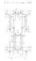
図2(A)は、第1形SRAMセル10の半導体領域(拡散層)及びポリシリコン配線のパターン図であり、図2(B)は図2(A)のIIB−IIB線に沿った断面図である。図3(A)は、図2(A)のパターンに、メタル配線第1層の配線パターンを重ね合わせたパターン図である。図3(B)は、図3(A)のパターンに、メタル配線第2層の配線パターンを重ね合わせたパターン図である。図6(A)は、図3(B)のレイアウトパターンに対応した回路図である。第1形SRAMセル10の長い辺及び短い辺に平行な方向をそれぞれ図示X方向及びY方向とする。
【0024】
図2(A)において、図10との関係では、pMOS領域12はpMOS領域2に対応し、nMOS領域13A及び13BはnMOS領域3に対応し、素子分離領域14A及び14Bは素子分離領域4に対応している。すなわち、第1形SRAMセル10のX方向について、中央部にpMOS領域12が配置され、一端側及び他端側にそれぞれnMOS領域13A及び13Bが配置され、pMOS領域12とnMOS領域13Aとの間及びpMOS領域12とnMOS領域13Bとの間にそれぞれ素子分離領域14A及び14Bが形成されている。nMOS領域13A及び13Bはそれぞれ、図2(B)に示す如く、n型半導体基板15のp型ウエル16内及び17内に形成されている。これに対しpMOS領域12は、n型半導体基板15の表面部に形成されている。フィールド酸化膜14a及び14bはそれぞれ、素子分離領域14A及び14Bの一部である。
【0025】
pMOS領域12にはpMOSトランジスタQP1とpMOSトランジスタQP2とが形成され、nMOS領域13AにはnMOSトランジスタQN1とnMOSトランジスタQN3とが形成され、nMOS領域13BにはnMOSトランジスタQN2とnMOSトランジスタQN4とが形成されている。pMOSトランジスタQP1とnMOSトランジスタQN1とでフリップフロップの一方のCMOSインバータが構成され、pMOSトランジスタQP2とnMOSトランジスタQN2とでフリップフロップの他方のCMOSインバータが構成される。nMOSトランジスタQN3及びQN4はいずれも転送ゲートである。
【0026】
図2(A)のパターンは、第1形SRAMセル10の中央点について点対称である。これにより、SRAM製造において、露光パターンの処理が簡単になる。同図において、符号中のs及びdはそれぞれソース領域及びドレイン領域であることを示し、符号の先頭のP及びNはそれぞれp型半導体領域及びn型半導体領域であることを示し、符号中の中間部の数字はトランジスタの符号中の数字と一致している。
【0027】
pMOSトランジスタQP1は、p型半導体領域P1s及びP1dと、これらの間のチャンネル領域と、チャンネル領域の上方にゲート酸化膜を介して配置されたゲートとを備え、このゲートはポリシリコン配線G10の一部である。pMOSトランジスタQP2、nMOSトランジスタQN1、QN2、QN3及びQN4のゲートはそれぞれ、ポリシリコン配線G20、G10、W10及びW20の一部である。pMOSトランジスタQP2のp型半導体領域P2s及びP2dはそれぞれpMOSトランジスタQP1のp型半導体領域P1s及びP1dに対応している。nMOSトランジスタQN1は、n型半導体領域N1s及びN1dと、これらの間のチャンネル領域と、チャンネル領域の上方にゲート酸化膜を介して配置されたゲートとを備えている。nMOSトランジスタQN2〜QN4についてもnMOSトランジスタQN1と同様である。
【0028】
nMOSトランジスタQN1とpMOSトランジスタQP1とがY方向の一方側に配置されているので、ポリシリコン配線G10が略直線となり、同様に、nMOSトランジスタQN2とpMOSトランジスタQP2とがY方向他方側に配置されているので、ポリシリコン配線G20が略直線となっている。nMOSトランジスタQN1とnMOSトランジスタQN3とは、n型半導体領域N1dが共通でY方向に配置され、nMOSトランジスタQN2とnMOSトランジスタQN4とは、n型半導体領域N2dが共通でY方向に配置されている。また、pMOSトランジスタQP1及びQP2がそれぞれpMOS領域12のnMOSトランジスタQN1側及びnMOSトランジスタQN2側に配置されている。これらのことは、第1形SRAMセル10のY方向の幅を短くし且つ第1形SRAMセル10の占有面積を狭くするのに寄与している。
【0029】
図3(A)では、複雑化を避けるため図2(A)中の符号を省略している。図3(A)のパターンにおいても、図2(A)と同様に第1形SRAMセル10の中央点について点対称である。
メタル配線G11及びG21は上記2つのインバータ間のクロス接続に用いられている。すなわち、ポリシリコン配線G20の一端とn型半導体領域N1dとの間が、コンタクトホールCa1及びCa2を通ってメタル配線G21で接続され、ポリシリコン配線G10の一端とn型半導体領域N2dとの間が、コンタクトホールCb1及びCb2を通ってメタル配線G11で接続されている。
【0030】
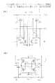
電源配線については、第1形SRAMセル10のX方向中央部に電源電位供給線VCCが配置され、第1形SRAMセル10のX方向一端部及び他端部にそれぞれ基準電位供給線VSS11及びVSS12が配置されている。これら電源配線VCC、VS11及びVSS12はいずれもY方向と平行になっている。電源電位供給線VCCは、コンタクトホールCc1及びCc2を通ってそれぞれ下方のp型半導体領域P1s及びP2sに接続されている。基準電位供給線VSS11及びVSS12はいずれも、隣合うSRAMセルとで共用するために、その中心線が第1形SRAMセル10の境界線(点線)に一致している。基準電位供給線VSS11はコンタクトホールCd1を通って下方のn型半導体領域N1sに接続され、基準電位供給線VSS12はコンタクトホールCd2を通って下方のn型半導体領域N2sに接続されている。
【0031】
メタル配線B11、B21、W11及びW21はいずれも下層と上層との間を接続するための中間的な配線である。メタル配線B11は、コンタクトホールCa3を通って下方のn型半導体領域N3に接続され、メタル配線B21はコンタクトホールCb3を通って下方のn型半導体領域N4に接続され、メタル配線W11はコンタクトホールCe1を通って下方のポリシリコン配線W10に接続され、メタル配線W21はコンタクトホールCf1を通って下方のポリシリコン配線W20に接続されている。
【0032】
図3(B)では、複雑化を避けるため図2(A)及び図3(A)中の符号を省略している。図3(B)のパターンにおいても、図3(A)と同様に第1形SRAMセル10の中央点について点対称である。
電源配線の配線幅を狭くして集積度を高めるために、基準電位供給線VSS21及びVSS22がそれぞれ絶縁層を介し基準電位供給線VSS11及びVSS12の真上に配置されている。一対のビット線BL及び*BLはそれぞれ、基準電位供給線VSS21及びVSS22でシールドしてノイズを低減するために、基準電位供給線VSS21及びVSS22の近くにこれらと平行に配置されている。ビット線BLは、コンタクトホールCa4を通って下方のメタル配線B11に接続され、ビット線*BLは、コンタクトホールCb4を通って下方のメタル配線B21に接続されている。また、電源電位供給線VCCの両側に電源電位供給線VCCに沿ってデータ線DL及び*DLが配置され、これらは電源電位供給線VCCによりシールドされてノイズが低減されている。なお、図6及び図7ではデータ線DL及び*DLを省略している。
【0033】
メタル配線W12及びW22はいずれも下層と上層との間を接続するための中間的な配線である。メタル配線W12は、コンタクトホールCe2を通って下方のメタル配線W11に接続され、コンタクトホールCe3を通って上方のワード線WLに接続されている。ワード線WLは、第3配線層であり、パターンの複雑化を避けるためにその中心線のみを示している。同様に、メタル配線W22は、コンタクトホールCf2を通って下方のメタル配線W21に接続され、コンタクトホールCf3を通って上方のワード線WLに接続されている。
【0034】
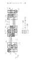
図4は第2形SRAMセル20のパターン図であり、このパターンは、図3(B)の第1形SRAMセル10のパターンをX方向中央線(WLの中央線)について線対称にし、メタル配線W12、W22、W11及びW21を除去し、かつ、ポリシリコン配線W10及びW20のセル中央側端部を除去したものとなっている。この対称性により、空き領域21及び22が第1形SRAMセル10との関係で有効利用され、パターンの短縮化が図られている。
【0035】
すなわち、第1形SRAMセル10と第2形SRAMセル20とを、セル境界である点線を一致させて、図5に示す如くビット線方向へ並置すると、図3(B)のメタル配線W21及びW22が図4の空き領域22に配置される。空き領域21には、図5の下方に第1形SRAMセル10を並置することにより、第1形SRAMセル10のメタル配線W11及びW12が入り込む。第2形SRAMセル20のポリシリコン配線W3及びW4は、次のようにして第2形SRAMセル20上のワード線WLに接続される。すなわち、第2形SRAMセル20の長手方向両側に第2形SRAMセル20と隣合うように第1形SRAMセル10を配置する。これにより第1形SRAMセル10のポリシリコン配線W20が第2形SRAMセル20のポリシリコン配線W3に接続され、ポリシリコン配線W3がポリシリコン配線W20を介して第1形SRAMセル10のワード線WLに接続される。同様に、第1形SRAMセル10のポリシリコン配線W10が第2形SRAMセル20のW4に接続され、ポリシリコン配線W4がポリシリコン配線W10を介して第1形SRAMセル10のワード線WLに接続される。
【0036】
このような配置及びワード線WLの接続を図1(C)に示す。
セルアレイ30は、第1形SRAMセル10と第2形SRAMセル20とがX方向及びY方向について互いに隣合うように境界線を一致させて格子状に配置されている。この図から、第2形SRAMセル20のポリシリコン配線W3及びW4のワード線WLへの接続を容易に理解することができる。BL0〜BL3及び*BL0〜*BL3はビット線であり、WL0〜WL3はワード線である。
【0037】
本実施形態によれば、図2(A)に示す如くnMOS領域13AとnMOS領域13Bとの間にpMOS領域12が配置され、nMOS領域13Aから13Bへの方向と直角な方向にビット線が配置されているので、SRAMセル当たりのビット線長を従来よりも短くすることができ、これにより、ビット線の容量及び抵抗が低減され、半導体装置のアクセス速度が従来よりも向上する。
【0038】
また、図10のSRAMセルでは電源電位供給線VCC及び基準電位供給線VSSがワード線WLと平行であるので、SRAMにおいて1つのワード線WLを選択した場合に、選択されたワード線WLに沿ったSRAMセルには一対の電源電位供給線VCC及び基準電位供給線VSSから電圧が供給される。これに対し、図1(C)では、電源配線がワード線と直角な方向に沿って配置されているので、1つのワード線を選択した場合に、このワード線に沿った各SRAMセルについて一対の電源配線から電圧が供給されるので、電源配線幅を広くしたのと同じ効果が得られ、電源電圧の変動が従来よりも低減されてノイズ耐性が向上する。
【0039】
図8(A)は、本実施形態でのSRAMセルアレイ中でのデータバスDBの配置を示し、図8(B)は従来のSRAMセルアレイ中でのデータバスDBAの配置を示す。図8(A)及び図8(B)中、点線はSRAMセルの境界を示す。
従来ではセルアレイブロック30Aの一端側でビット線をデータバスDBAに接続していたが、本実施例では2つのセルアレイブロック30毎にセルアレイブロック30の外端部においてビット線BL及び*BLをそれぞれデータ線DL及び*DLに接続している。ビット線BL及び*BLは各SRAMセルで転送ゲートに接続されているので負荷が比較的大きいが、データ線DL及び*DLにはこのような負荷はない。このため、データバスDBと直角方向のメモリセル数を従来よりも多くすることができ、これによりデータバスDBの長さを従来よりも短くでき、その分、データバスDBの専有面積を狭くすることができ、記憶容量が従来よりも増加する。図3(B)に示す如く、データ線DL及び*DLは、pMOS領域12上の空き部分に配置されているので、データ線DL及び*DLによるセル面積増大は避けられる。
【0040】
なお、本発明には外にも種々の変形例が含まれる。
例えば、上記実施形態では、点線で示すセル外形が矩形である好ましい場合を説明したが、本発明の効果はSRAMセルの外形が矩形でなくても得られ、SRAMセルは例えば図9(A)〜(C)に示すような外形であってもよい。
また、コンタクトホール下部にローカルインターコネクトを用いることにより、図3(B)中のビット線BLを基準電位供給線VSS21側のnMOSトランジスタQN1及びQN3上に配置して、セルのX方向長さを短縮することも可能である。
【0041】
さらに、図3(A)ではコンタクトホールCa1の位置でメタル配線G21、ポリシリコン配線G20及びp型半導体領域P1dの間を接続しているが、コンタクトホールCe2及びCe3のように、メタル配線G21とポリシリコン配線G20との間及びポリシリコン配線G20とp型半導体領域P1dとの間を互いに異なる位置でコンタクトホールを通って接続することにより、配線層の凹凸を低減させて信頼性を向上させるようにしてもよい。
【0042】
また、データ線DL及び*DLを備えない構成であってもよいことは勿論である。
【図面の簡単な説明】
【図1】(A)は第1形SRAMセルの概略パターン図、(B)は第2形SRAMセルの概略パターン図、(C)は第1形及び第2形のSRAMセルが交互に配置されたセルアレイの概略パターン図である。
【図2】(A)は第1形SRAMセルの半導体領域及びポリシリコン配線のパターン図、(B)は(A)中のIIB−IIB線に沿った断面図である。
【図3】(A)は図2(A)のパターンにメタル配線第1層の配線パターンを重ね合わせたパターン図、(B)は(A)のパターンにメタル配線第2層の配線パターンを重ね合わせたパターン図である。
【図4】第2形SRAMセルのパターン図である。
【図5】第1形SRAMセルと第2形SRAMセルとがビット線方向へ並置されたパターン図である。
【図6】(A)は図3(B)のレイアウトパターンに対応した回路図、(B)は図4のレイアウトパターンに対応した回路図である。
【図7】図5のレイアウトパターンに対応した回路図である。
【図8】(A)は本実施形態のSRAMセルアレイ中でのデータバスの配置図であり、(B)は従来のSRAMセルアレイ中でのデータバス配置図である。
【図9】(A)〜(C)はSRAMセルの変形例を示すセル外形図である。
【図10】従来のSRAMセルのパターン図である。
【図11】(A)は図10のレイアウトパターンに対応した回路図であり、(B)は(A)の接続を分かり易くした一般的な回路図である。
【符号の説明】
10 第1形SRAMセル
12 pMOS領域
13A、13B nMOS領域
14A、14B 素子分離領域
14a、14b フィールド酸化膜
15 n型半導体基板
16、17 p型ウエル
20 第2形SRAMセル
30 セルアレイブロック
QP1、QP2 pMOSトランジスタ
QN1〜QN4 nMOSトランジスタ
P1s、P2s、P1d、P2d p型半導体領域
N1s、N1d、N2s、N2d、N3、N4 n型半導体領域
G1、G2、G10、G20、W10、W20 ポリシリコン配線
S1〜S4、B11、B21、W11、W21、W12、W22 メタル配線
BL、*BL ビット線
DL、*DL データ線
WL ワード線
DB、DBA データバス[0001]
BACKGROUND OF THE INVENTION
The present invention relates to a CMOS type SRAM cell.WithThe present invention relates to a semiconductor device.
[0002]
[Prior art]
This type of SRAM has a memory cell that is not a charge-holding type like a DRAM but a current-driven type using a flip-flop, so that it can be accessed at high speed and is used as a cache memory. Accordingly, higher speed is required.
[0003]
FIG. 10 is a pattern diagram of a
In the
[0004]
The metal wirings S1 to S4 and the power supply potential supply line VCC are a metal wiring first layer, the reference potential supply line VSS is a metal wiring second layer, and the bit lines BL and * BL are a metal wiring third layer.
The polysilicon wiring G1 includes the gates of the pMOS transistor QP1 and the nMOS transistor QN1, and one end thereof is connected to the p-type semiconductor region P2d of the pMOS transistor QP2 through a contact hole. Polysilicon wiring G2 includes the gates of pMOS transistor QP2 and nMOS transistor QN2, and one end thereof is connected to the n-type semiconductor region N1d of nMOS transistor QN1 through a contact hole. The p-type semiconductor region P1d of the pMOS transistor QP1 and the n-type semiconductor region N1d of the nMOS transistor QN1 are connected by a metal wiring S1 through a contact hole, and the p-type semiconductor region P2d of the pMOS transistor QP2 and the n-type of the nMOS transistor QN2 The semiconductor region N2d is connected by a metal wiring S2 through a contact hole. The n-type semiconductor region N1s of the nMOS transistor QN1 passes through the contact hole and is connected to the reference potential supply line VSS by the metal wiring S3. The n-type semiconductor region N2s of the nMOS transistor QN2 passes through the contact hole and is connected to the reference by the metal wiring S4. It is connected to the potential supply line VSS.
[0005]
In the case of reading data written in the
[0006]
[Problems to be solved by the invention]
In the
[0007]
In view of the above problems, an object of the present invention is to provide a CMOS type SRAM cell capable of speeding up access.WithA semiconductor device is provided.
[0009]
[Means for solving the problems and their effects]
In the semiconductor device of the present invention,
A first nMOS region having first and third nMOS transistors;
A second nMOS region having second and fourth nMOS transistors;
A pMOS region disposed between the first nMOS region and the second nMOS region and having first and second pMOS transistors;
An element isolation region disposed between the first nMOS region and the pMOS region and between the second nMOS region and the pMOS region;
First and second bit lines;
A word line,
Have
The first and second nMOS transistors and the first and second pMOS transistors constitute a flip-flop for storing data,
The third nMOS transistor constitutes a first transfer gate connecting the first bit line and the flip-flop;
The fourth nMOS transistor constitutes a second transfer gate connecting the second bit line and the flip-flop;
The gates of the third and fourth nMOS transistors are connected to the word line;
A semiconductor device comprising an SRAM cell,
The first nMOS region, the pMOS region, and the second nMOS region are arranged side by side in a first direction.
The word line extends in the first direction;
The first and second bit lines extend in a second direction perpendicular to the first direction;
The gate of the first nMOS transistor and the gate of the first pMOS transistor are constituted by a first polysilicon wiring extending in the first direction,
The gate of the second nMOS transistor and the gate of the second pMOS transistor are constituted by a second polysilicon wiring extending in the first direction,
A gate of the third nMOS transistor is constituted by a third polysilicon wiring extending in the first direction;
A gate of the fourth nMOS transistor is constituted by a fourth polysilicon wiring extending in the first direction;
The first to fourth polysilicon wirings include a first wiring group including the first polysilicon wiring and the fourth polysilicon wiring, the second polysilicon wiring, and the third polysilicon. A second wiring group consisting of wiring,
The first wiring group and the second wiring group are arranged side by side in the second direction.,
The first polysilicon wiring is connected to the drain of the second pMOS transistor via a contact hole;
The second polysilicon wiring is connected to the drain of the first pMOS transistor through a contact hole.ing.
[0010]
According to the present invention, due to the above characteristics, the cell width in the second direction perpendicular to the first direction is narrower than that of the conventional one, whereby the bit line extending in the second direction per unit cell. Since the length can be made shorter than before, the access speed of the CMOS type SRAM cell can be improved more than before.In addition, there is an effect that wiring by polysilicon is performed efficiently.
In the first aspect of the present invention, the first nMOS transistor, the fourth nMOS transistor, and the first pMOS transistor are in a direction substantially perpendicular to the first direction (longitudinal direction) of the first region, the second region, and the third region, respectively. Arranged on one end side,
The third nMOS transistor, the second nMOS transistor, and the second pMOS transistor are disposed on the other end side in a direction substantially perpendicular to the longitudinal direction of the first region, the second region, and the third region, respectively.
[0011]
According to the first aspect, the wiring including the gates of the first nMOS transistor and the first pMOS transistor is substantially straight, and the wiring including the gates of the second nMOS transistor and the second pMOS transistor is substantially straight. There is an effect that the occupied area can be reduced.
BookIn a second aspect of the invention, the first nMOS transistor and the third nMOS transistor are juxtaposed in a direction substantially perpendicular to the longitudinal direction,
One n-type semiconductor region of the first nMOS transistor and one n-type semiconductor region of the 3nMOS transistor are common regions,
The second nMOS transistor and the fourth nMOS transistor are juxtaposed in a direction substantially perpendicular to the longitudinal direction;
One n-type semiconductor region of the second nMOS transistor and one n-type semiconductor region of the 4nMOS transistor are common regions.
[0012]
According to the second aspect, since the first region and the second region are compact, the occupation area of the CMOS type SRAM cell can be reduced.
BookIn a third aspect of the invention, the first pMOS transistor is disposed on the first region side in the third region,
The second pMOS transistor is disposed on the second region side in the third region.
[0013]
According to the third aspect, since the transistors having a larger coupling relationship are present at positions facing each other, the inter-element wiring length in the CMOS SRAM cell is shortened, and the occupation area of the CMOS SRAM cell is reduced. Has the effect of being able to.
[0014]
First of the present invention4In an embodiment, the CMOS SRAM cell is rectangular.
[0015]
Although the CMOS type SRAM cell of the present invention is not limited to a rectangle, the rectangle is advantageous for shortening the bit line.4According to the aspect, there is an effect that the bit line can be further shortened.
First of the present invention5In the aspect, the power supply potential supply line is disposed above the third region along a direction substantially perpendicular to the longitudinal direction,
The reference potential supply line is arranged along each of the sides of the rectangle facing in the longitudinal direction.
[0016]
This first5According to the aspect, since the power supply wiring is arranged along the direction perpendicular to the word line, when one word line is selected in the SRAM, each SRAM cell along the word line is separated from the pair of power supply wirings. The same effect as when the voltage is supplied and the power supply wiring width is widened is obtained, and the fluctuation of the power supply voltage is reduced as compared with the conventional case and the noise resistance is improved.
[0017]
First of the present invention6In the aspect, the first to fourth nMOS transistors and the first and second pMOS transistors are arranged substantially symmetrically with respect to a central point of the rectangle.
According to the seventh aspect, in the SRAM manufacturing, there is an effect that the processing of the exposure pattern is simplified due to the symmetry. Further, since the first and second CMOS inverters have the same shape, the operation is stable.
[0018]
First of the present invention7An aspect includes a memory cell array in which the CMOS type SRAM cells of any of the above aspects are arranged in a lattice pattern,
A peripheral circuit for writing and reading data to and from the memory cell array;
A semiconductor device having
[0019]
First of the present invention8In an aspect, the above6A CMOS SRAM cell of the embodiment,
The CMOS type SRAM cell has a first shape and a second shape that are symmetrical with respect to one side when the one side in the longitudinal direction of the rectangle is arranged in common,
In the memory cell array, the first-type CMOS type SRAM cells and the second-type CMOS type SRAM cells are alternately arranged in the longitudinal direction and a direction perpendicular to the longitudinal direction,
A word line is arranged in the longitudinal direction of the rectangle;
The gate of the third nMOS transistor of the first type CMOS SRAM cell is connected to the word line via a metal wiring;
The gate of the fourth nMOS transistor of the second type CMOS SRAM cell is a continuous wiring with the gate of the adjacent third nMOS transistor of the first type,
A gate of the fourth nMOS transistor of the first type CMOS type SRAM cell is connected to the word line via a metal wiring;
The gate of the third nMOS transistor of the second type CMOS SRAM cell is continuous with the gate of the adjacent fourth nMOS transistor of the first type.
[0020]
This first8According to the aspect, since one vacant area of the CMOS SRAM cell adjacent in the bit line direction can be effectively used as the other word line connection area due to the line symmetry, high integration of the CMOS SRAM cell array can be achieved. There is an effect that it becomes possible.
First of the present invention9In an aspect, the CMOS type SRAM cell has a data line parallel to the bit line,
The data line is connected to the bit line for each of the plurality of CMOS SRAM cells arranged continuously in the direction of the bit line,
The data line is connected to a data bus arranged between the CMOS type SRAM cell blocks.
[0021]
Since the bit line is connected to the transfer gate in each SRAM cell, the load is relatively large, but the data line does not have such a load.
This first9In one embodiment, the data line is connected to the bit line for each of a plurality of CMOS type SRAM cells arranged continuously in the direction of the bit line, and the data line is arranged between the CMOS type SRAM cell blocks. Therefore, the number of memory cells in the direction perpendicular to the data bus can be increased more than before, and the length of the data bus can be made shorter than before, thereby reducing the area occupied by the data bus. There is an effect that can be done.
[0022]
DETAILED DESCRIPTION OF THE INVENTION
Hereinafter, an embodiment of the present invention will be described with reference to the drawings.
FIG. 1A shows a schematic pattern of the first
[0023]
2 to 7, elements corresponding to those in FIGS. 10 and 11 are denoted by the same reference numerals for easy association even if the pattern shapes are different. The elements corresponding to the first
2A is a pattern diagram of the semiconductor region (diffusion layer) and the polysilicon wiring of the first
[0024]
2A, in the relationship with FIG. 10, the pMOS region 12 corresponds to the
[0025]
A pMOS transistor QP1 and a pMOS transistor QP2 are formed in the pMOS region 12, an nMOS transistor QN1 and an nMOS transistor QN3 are formed in the nMOS region 13A, and an nMOS transistor QN2 and an nMOS transistor QN4 are formed in the nMOS region 13B. ing. The pMOS transistor QP1 and the nMOS transistor QN1 constitute one CMOS inverter of the flip-flop, and the pMOS transistor QP2 and the nMOS transistor QN2 constitute the other CMOS inverter of the flip-flop. The nMOS transistors QN3 and QN4 are both transfer gates.
[0026]
The pattern of FIG. 2A is point symmetric about the central point of the
[0027]
The pMOS transistor QP1 includes p-type semiconductor regions P1s and P1d, a channel region between the p-type semiconductor regions P1s and P1d, and a gate disposed above the channel region via a gate oxide film. The gate is a part of the polysilicon wiring G10. Part. The gates of the pMOS transistor QP2 and the nMOS transistors QN1, QN2, QN3, and QN4 are part of the polysilicon wirings G20, G10, W10, and W20, respectively. The p-type semiconductor regions P2s and P2d of the pMOS transistor QP2 correspond to the p-type semiconductor regions P1s and P1d of the pMOS transistor QP1, respectively. The nMOS transistor QN1 includes n-type semiconductor regions N1s and N1d, a channel region between them, and a gate disposed above the channel region via a gate oxide film. The nMOS transistors QN2 to QN4 are the same as the nMOS transistor QN1.
[0028]
Since the nMOS transistor QN1 and the pMOS transistor QP1 are arranged on one side in the Y direction, the polysilicon wiring G10 is substantially straight, and similarly, the nMOS transistor QN2 and the pMOS transistor QP2Is in the Y directionSince it is arranged on the side, the polysilicon wiring G20 is substantially straight. The nMOS transistor QN1 and the nMOS transistor QN3 share the n-type semiconductor region N1d in the Y direction, and the nMOS transistor QN2 and the nMOS transistor QN4 share the n-type semiconductor region N2d in the Y direction. The pMOS transistors QP1 and QP2 are arranged on the nMOS transistor QN1 side and the nMOS transistor QN2 side of the pMOS region 12, respectively. These contribute to reducing the width in the Y direction of the first
[0029]
In FIG. 3A, reference numerals in FIG. 2A are omitted to avoid complication. The pattern of FIG. 3A is also point-symmetric with respect to the central point of the
Metal wirings G11 and G21 are used for cross connection between the two inverters. That is, one end of the polysilicon wiring G20 and the n-type semiconductor region N1d are connected by the metal wiring G21 through the contact holes Ca1 and Ca2, and one end of the polysilicon wiring G10 and the n-type semiconductor region N2d are connected. The metal wiring G11 is connected through the contact holes Cb1 and Cb2.
[0030]
As for the power supply wiring, a power supply potential supply line VCC is arranged at the center in the X direction of the first
[0031]
The metal wirings B11, B21, W11, and W21 are all intermediate wirings for connecting the lower layer and the upper layer. The metal wiring B11 is connected to the lower n-type semiconductor region N3 through the contact hole Ca3, the metal wiring B21 is connected to the lower n-type semiconductor region N4 through the contact hole Cb3, and the metal wiring W11 is connected to the contact hole Ce1. The metal wiring W21 is connected to the lower polysilicon wiring W20 through the contact hole Cf1.
[0032]
In FIG. 3B, reference numerals in FIGS. 2A and 3A are omitted to avoid complication. 3B is also point-symmetric with respect to the center point of the
In order to reduce the wiring width of the power supply wiring and increase the degree of integration, the reference potential supply lines VSS21 and VSS22 are respectivelyThrough the insulating layerIt is arranged directly above the reference potential supply lines VSS11 and VSS12. The pair of bit lines BL and * BL are arranged near and in parallel with the reference potential supply lines VSS21 and VSS22 in order to reduce noise by shielding with the reference potential supply lines VSS21 and VSS22, respectively. The bit line BL is connected to the lower metal wiring B11 through the contact hole Ca4, and the bit line * BL is connected to the lower metal wiring B21 through the contact hole Cb4. Further, data lines DL and * DL are arranged on both sides of the power supply potential supply line VCC along the power supply potential supply line VCC, and these are shielded by the power supply potential supply line VCC to reduce noise. 6 and 7, the data lines DL and * DL are omitted.
[0033]
The metal wirings W12 and W22 are both intermediate wirings for connecting the lower layer and the upper layer. The metal wiring W12 is connected to the lower metal wiring W11 through the contact hole Ce2, and is connected to the upper word line WL through the contact hole Ce3. The word line WL is a third wiring layer, and only its center line is shown in order to avoid complication of the pattern. Similarly, the metal wiring W22 passes through the contact hole Cf2 and the lower metal wiring.W21To the upper word line WL through the contact hole Cf3.
[0034]
FIG. 4 is a pattern diagram of the second
[0035]
That is, the first-
[0036]
Such an arrangement and connection of the word lines WL are shown in FIG.
The
[0037]
According to the present embodiment, as shown in FIG. 2A, the pMOS region 12 is arranged between the nMOS region 13A and the nMOS region 13B, and the bit lines are arranged in a direction perpendicular to the direction from the nMOS region 13A to 13B. Therefore, the bit line length per SRAM cell can be made shorter than before, thereby reducing the capacity and resistance of the bit line and improving the access speed of the semiconductor device than before.
[0038]
In the SRAM cell of FIG. 10, the power supply potential supply line VCC and the reference potential supply line VSS are parallel to the word line WL. Therefore, when one word line WL is selected in the SRAM, it follows the selected word line WL. The SRAM cell is supplied with a voltage from a pair of power supply potential supply line VCC and reference potential supply line VSS. On the other hand, in FIG. 1C, since the power supply wiring is arranged along a direction perpendicular to the word line, when one word line is selected, a pair of SRAM cells along the word line is selected. Since the voltage is supplied from the power supply wiring, the same effect as the widening of the power supply wiring width is obtained, the fluctuation of the power supply voltage is reduced as compared with the conventional one, and the noise resistance is improved.
[0039]
FIG. 8A shows the arrangement of the data bus DB in the SRAM cell array according to this embodiment, and FIG. 8B shows the arrangement of the data bus DBA in the conventional SRAM cell array.In FIG. 8A and FIG. 8B, the dotted line indicates the boundary of the SRAM cell.
Conventionally, one end of the cell array block 30A~ sideIn this embodiment, the bit line is connected to the data bus DBA.cellBit lines BL and * BL are connected to data lines DL and * DL at the outer ends of the
[0040]
Note that the present invention includes various other modifications.
For example, in the above embodiment,, Indicated by dotted lineAlthough the preferable case where the cell outer shape is rectangular has been described, the effect of the present invention can be obtained even when the SRAM cell has an outer shape that is not rectangular. For example, the SRAM cell has an outer shape as shown in FIGS. There may be.
Further, by using a local interconnect under the contact hole, the bit line BL in FIG. 3B is arranged on the nMOS transistors QN1 and QN3 on the reference potential supply line VSS21 side, thereby reducing the length of the cell in the X direction. It is also possible to do.
[0041]
Further, in FIG. 3A, the metal wiring G21, the polysilicon wiring G20, and the p-type semiconductor region P1d are connected at the position of the contact hole Ca1, but the metal wiring G21 is connected to the metal wiring G21 like the contact holes Ce2 and Ce3. By connecting the polysilicon wiring G20 and the polysilicon wiring G20 and the p-type semiconductor region P1d through contact holes at different positions, the unevenness of the wiring layer is reduced and the reliability is improved. It may be.
[0042]
Of course, the data lines DL and * DL may not be provided.
[Brief description of the drawings]
1A is a schematic pattern diagram of a first type SRAM cell, FIG. 1B is a schematic pattern diagram of a second type SRAM cell, and FIG. 1C is an alternating arrangement of first and second type SRAM cells; FIG.
FIG. 2A is a pattern diagram of a semiconductor region and polysilicon wiring of a first type SRAM cell, and FIG. 2B is a cross-sectional view taken along line IIB-IIB in FIG.
3A is a pattern diagram in which the wiring pattern of the first layer of metal wiring is superimposed on the pattern of FIG. 2A, and FIG. 3B is a pattern of wiring of the second layer of metal wiring on the pattern of FIG. FIG.
FIG. 4 is a pattern diagram of a second type SRAM cell;
FIG. 5 is a pattern diagram in which a first type SRAM cell and a second type SRAM cell are juxtaposed in the bit line direction;
6A is a circuit diagram corresponding to the layout pattern of FIG. 3B, and FIG. 6B is a circuit diagram corresponding to the layout pattern of FIG. 4;
7 is a circuit diagram corresponding to the layout pattern of FIG. 5;
8A is a layout diagram of data buses in the SRAM cell array of this embodiment, and FIG. 8B is a data bus layout diagram in the conventional SRAM cell array.
FIGS. 9A to 9C are cell outline diagrams showing modifications of the SRAM cell. FIGS.
FIG. 10 is a pattern diagram of a conventional SRAM cell.
11A is a circuit diagram corresponding to the layout pattern of FIG. 10, and FIG. 11B is a general circuit diagram in which the connection of FIG.
[Explanation of symbols]
10 First type SRAM cell
12 pMOS region
13A, 13B nMOS region
14A, 14B element isolation region
14a, 14b Field oxide film
15 n-type semiconductor substrate
16, 17 p-type well
20 Second SRAM cell
30 cell array block
QP1, QP2 pMOS transistors
QN1-QN4 nMOS transistors
P1s, P2s, P1d, P2d p-type semiconductor regions
N1s, N1d, N2s, N2d, N3, N4 n-type semiconductor regions
G1, G2, G10, G20, W10, W20 Polysilicon wiring
S1-S4, B11, B21, W11, W21, W12, W22 Metal wiring
BL, * BL Bit line
DL, * DL data line
WL Word line
DB, DBA Data bus
Claims (24)
Translated fromJapanese第2及び第4のnMOSトランジスタを有する第2のnMOS領域と、
前記第1のnMOS領域と前記第2のnMOS領域の間に配置され、第1及び第2のpMOSトランジスタを有するpMOS領域と、
前記第1のnMOS領域と前記pMOS領域の間、及び前記第2のnMOS領域と前記pMOS領域の間に配置された素子分離領域と、
第1及び第2のビット線と、
ワード線と、
を有し、
前記第1及び第2のnMOSトランジスタと前記第1及び第2のpMOSトランジスタとがデータを格納するためのフリップフロップを構成し、
前記第3のnMOSトランジスタが前記第1のビット線と前記フリップフロップの間を接続する第1のトランスファーゲートを構成し、
前記第4のnMOSトランジスタが前記第2のビット線と前記フリップフロップの間を接続する第2のトランスファーゲートを構成し、
前記第3及び第4のnMOSトランジスタのゲートが前記ワード線に接続された、
SRAMセルを備えた半導体装置であって、
前記第1のnMOS領域、前記pMOS領域、及び前記第2のnMOS領域は第1の方向に並べて配置され、
前記ワード線は前記第1の方向に延在し、
前記第1及び第2のビット線は前記第1の方向に対して垂直な第2の方向に延在し、
前記第1のnMOSトランジスタのゲートと前記第1のpMOSトランジスタのゲートは前記第1の方向に延在する第1のポリシリコン配線により構成され、
前記第2のnMOSトランジスタのゲートと前記第2のpMOSトランジスタのゲートは前記第1の方向に延在する第2のポリシリコン配線により構成され、
前記第3のnMOSトランジスタのゲートは前記第1の方向に延在する第3のポリシリコン配線により構成され、
前記第4のnMOSトランジスタのゲートは前記第1の方向に延在する第4のポリシリコン配線により構成され、
前記第1乃至第4のポリシリコン配線が、前記第1のポリシリコン配線及び前記第4のポリシリコン配線からなる第1の配線群と、前記第2のポリシリコン配線及び前記第3のポリシリコン配線からなる第2の配線群とから構成され、
前記第1の配線群と前記第2の配線群が前記第2の方向に並べて配置され、
前記第1のポリシリコン配線は前記第2のpMOSトランジスタのドレインとコンタクトホールを介して接続され、
前記第2のポリシリコン配線は前記第1のpMOSトランジスタのドレインとコンタクトホールを介して接続されたことを特徴とする半導体装置。A first nMOS region having first and third nMOS transistors;
A second nMOS region having second and fourth nMOS transistors;
A pMOS region disposed between the first nMOS region and the second nMOS region and having first and second pMOS transistors;
An element isolation region disposed between the first nMOS region and the pMOS region and between the second nMOS region and the pMOS region;
First and second bit lines;
A word line,
Have
The first and second nMOS transistors and the first and second pMOS transistors constitute a flip-flop for storing data,
The third nMOS transistor constitutes a first transfer gate connecting the first bit line and the flip-flop;
The fourth nMOS transistor constitutes a second transfer gate connecting the second bit line and the flip-flop;
The gates of the third and fourth nMOS transistors are connected to the word line;
A semiconductor device comprising an SRAM cell,
The first nMOS region, the pMOS region, and the second nMOS region are arranged side by side in a first direction,
The word line extends in the first direction;
The first and second bit lines extend in a second direction perpendicular to the first direction;
The gate of the first nMOS transistor and the gate of the first pMOS transistor are constituted by a first polysilicon wiring extending in the first direction,
The gate of the second nMOS transistor and the gate of the second pMOS transistor are constituted by a second polysilicon wiring extending in the first direction,
A gate of the third nMOS transistor is constituted by a third polysilicon wiring extending in the first direction;
A gate of the fourth nMOS transistor is constituted by a fourth polysilicon wiring extending in the first direction;
The first to fourth polysilicon wirings include a first wiring group including the first polysilicon wiring and the fourth polysilicon wiring, the second polysilicon wiring, and the third polysilicon. A second wiring group consisting of wiring,
The first wiring group and the second wiring group are arranged side by side in the second direction;
The first polysilicon wiring is connected to the drain of the second pMOS transistor via a contact hole;
2. The semiconductor device according to claim 1, wherein the second polysilicon wiring is connected to the drain of the first pMOS transistor through a contact hole.
前記第1のpMOSトランジスタと前記第1のnMOSトランジスタが電源電位供給線と基準電位供給線の間に互いに直列に接続され、
前記第2のpMOSトランジスタと前記第2のnMOSトランジスタが前記電源電位供給線と前記基準電位供給線の間に互いに直列に接続され、
前記第3のnMOSトランジスタは前記第1のビット線と前記第1のnMOSトランジスタのドレインの間に接続され、前記第4のnMOSトランジスタは前記第2のビット線と前記第2のnMOSトランジスタのドレインの間に接続され、
前記第1のpMOSトランジスタのゲートは前記第2のnMOSトランジスタのドレインに接続され、前記第2のpMOSトランジスタのゲートは前記第1のnMOSトランジスタのドレインに接続されたことを特徴とする半導体装置。The semiconductor device according to claim 1,
The first pMOS transistor and the first nMOS transistor are connected in series between a power supply potential supply line and a reference potential supply line;
The second pMOS transistor and the second nMOS transistor are connected in series between the power supply potential supply line and the reference potential supply line;
The third nMOS transistor is connected between the first bit line and the drain of the first nMOS transistor, and the fourth nMOS transistor is the drain of the second bit line and the second nMOS transistor. Connected between
A semiconductor device characterized in that the gate of the first pMOS transistor is connected to the drain of the second nMOS transistor, and the gate of the second pMOS transistor is connected to the drain of the first nMOS transistor.
前記電源電位供給線及び前記基準電位供給線は前記第2の方向に延在し、
前記電源電位供給線は前記第1のビット線と前記第2のビット線の間に配置され、
前記基準電位供給線は前記第1及び第2のビット線の前記電源電位供給線とは反対側に配置されたことを特徴とする半導体装置。The semiconductor device according to claim 2,
The power supply potential supply line and the reference potential supply line extend in the second direction,
The power supply potential supply line is disposed between the first bit line and the second bit line;
The semiconductor device according to claim 1, wherein the reference potential supply line is disposed on the opposite side of the first and second bit lines from the power supply potential supply line.
前記第1及び第4のnMOSトランジスタ、並びに前記第1のpMOSトランジスタはそれぞれ、前記第1及び第2のnMOS領域、並びに前記pMOS領域の、前記第2の方向の第1端側の領域に配置され、
前記第3及び第2のnMOSトランジスタ、並びに前記第2のpMOSトランジスタはそれぞれ、前記第1及び第2のnMOS領域、並びに前記pMOS領域の、前記第2の方向の第2端側の領域に配置されたことを特徴とする半導体装置。A semiconductor device according to any one of claims 1 to 3,
The first and fourth nMOS transistors and the first pMOS transistor are arranged in the first end region in the second direction of the first and second nMOS regions and the pMOS region, respectively. And
The third and second nMOS transistors and the second pMOS transistor are respectively disposed in the first and second nMOS regions and the pMOS region on the second end side in the second direction. A semiconductor device characterized by the above.
前記第1及び第3のnMOSトランジスタは半導体基板上の共通領域に、前記第2の方向に並べて配置され、
前記第2及び第4のnMOSトランジスタは前記半導体基板上の共通領域に、前記第2の方向に並べて配置されたことを特徴とする半導体装置。The semiconductor device according to claim 1,
The first and third nMOS transistors are arranged side by side in the second direction in a common region on a semiconductor substrate,
The semiconductor device according to claim 1, wherein the second and fourth nMOS transistors are arranged in the second direction in a common region on the semiconductor substrate.
前記第1のpMOSトランジスタは前記pMOS領域の、前記第1のnMOS領域近傍の領域に配置され、前記第2のpMOSトランジスタは前記pMOS領域の、前記第2のnMOS領域近傍の領域に配置されたことを特徴とする半導体装置。A semiconductor device according to claim 1,
The first pMOS transistor is arranged in a region of the pMOS region in the vicinity of the first nMOS region, and the second pMOS transistor is arranged in a region of the pMOS region in the vicinity of the second nMOS region. A semiconductor device.
前記SRAMセルの外形は矩形であることを特徴とする半導体装置。A semiconductor device according to claim 1,
A semiconductor device characterized in that an external shape of the SRAM cell is rectangular.
前記SRAMセルのパターンレイアウトは前記SRAMセルの中心点に対して実質的に対称であることを特徴とする半導体装置。A semiconductor device according to claim 1,
2. A semiconductor device according to claim 1, wherein a pattern layout of the SRAM cell is substantially symmetrical with respect to a center point of the SRAM cell.
前記第1の方向は前記SRAMセルの矩形の長辺に沿った方向であり、
前記第2の方向は前記SRAMセルの矩形の短辺に沿った方向であることを特徴とする半導体装置。The semiconductor device according to claim 7,
The first direction is a direction along the long side of the rectangular shape of the SRAM cell;
The semiconductor device according to claim 2, wherein the second direction is a direction along a rectangular short side of the SRAM cell.
前記SRAMセルはマイクロプロセッサのためのキャッシュメモリを構成することを特徴とする半導体装置。A semiconductor device according to claim 1,
The SRAM cell constitutes a cache memory for a microprocessor.
前記メモリセルアレイに接続され、前記メモリセルアレイに対してデータの書き込み及び読み出しの動作を行う周辺回路と
を備えた半導体装置であって、前記複数のSRAMセルの各々は、
第1及び第3のnMOSトランジスタを有する第1のnMOS領域と、
第2及び第4のnMOSトランジスタを有する第2のnMOS領域と、
前記第1のnMOS領域と前記第2のnMOS領域の間に配置され、第1及び第2のpMOSトランジスタを有するpMOS領域と、
前記第1のnMOS領域と前記pMOS領域の間、及び前記第2のnMOS領域と前記pMOS領域の間に配置された素子分離領域と、
第1及び第2のビット線と、
ワード線と、
を有し、更に
前記第1及び第2のnMOSトランジスタと前記第1及び第2のpMOSトランジスタとがデータを格納するためのフリップフロップを構成し、
前記第3のnMOSトランジスタが前記第1のビット線と前記フリップフロップの間を接続する第1のトランスファーゲートを構成し、
前記第4のnMOSトランジスタが前記第2のビット線と前記フリップフロップの間を接続する第2のトランスファーゲートを構成し、
前記第3及び第4のnMOSトランジスタのゲートが前記ワード線に接続され、
前記第1のnMOS領域、前記pMOS領域、及び前記第2のnMOS領域は第1の方向に並べて配置され
前記ワード線は前記第1の方向に延在し、
前記第1及び第2のビット線は前記第1の方向に対して垂直な第2の方向に延在し、
前記第1のnMOSトランジスタのゲートと前記第1のpMOSトランジスタのゲートは前記第1の方向に延在する第1のポリシリコン配線により構成され、
前記第2のnMOSトランジスタのゲートと前記第2のpMOSトランジスタのゲートは前記第1の方向に延在する第2のポリシリコン配線により構成され、
前記第3のnMOSトランジスタのゲートは前記第1の方向に延在する第3のポリシリコン配線により構成され、
前記第4のnMOSトランジスタのゲートは前記第1の方向に延在する第4のポリシリコン配線により構成され、
前記第1乃至第4のポリシリコン配線が、前記第1のポリシリコン配線及び前記第4のポリシリコン配線からなる第1の配線群と、前記第2のポリシリコン配線及び前記第3のポリシリコン配線からなる第2の配線群とから構成され、
前記第1の配線群と前記第2の配線群が前記第2の方向に並べて配置され、
前記第1のポリシリコン配線は前記第2のpMOSトランジスタのドレインとコンタクトホールを介して接続され、
前記第2のポリシリコン配線は前記第1のpMOSトランジスタのドレインとコンタクトホールを介して接続されたことを特徴とする半導体装置。A memory cell array having a plurality of SRAM cells arranged in a lattice pattern;
And a peripheral circuit connected to the memory cell array and performing data writing and reading operations on the memory cell array, wherein each of the plurality of SRAM cells includes:
A first nMOS region having first and third nMOS transistors;
A second nMOS region having second and fourth nMOS transistors;
A pMOS region disposed between the first nMOS region and the second nMOS region and having first and second pMOS transistors;
An element isolation region disposed between the first nMOS region and the pMOS region and between the second nMOS region and the pMOS region;
First and second bit lines;
A word line,
And the first and second nMOS transistors and the first and second pMOS transistors constitute a flip-flop for storing data,
The third nMOS transistor constitutes a first transfer gate connecting the first bit line and the flip-flop;
The fourth nMOS transistor constitutes a second transfer gate connecting the second bit line and the flip-flop;
The gates of the third and fourth nMOS transistors are connected to the word line;
The first nMOS region, the pMOS region, and the second nMOS region are arranged side by side in a first direction, and the word line extends in the first direction,
The first and second bit lines extend in a second direction perpendicular to the first direction;
The gate of the first nMOS transistor and the gate of the first pMOS transistor are constituted by a first polysilicon wiring extending in the first direction,
The gate of the second nMOS transistor and the gate of the second pMOS transistor are constituted by a second polysilicon wiring extending in the first direction,
A gate of the third nMOS transistor is constituted by a third polysilicon wiring extending in the first direction;
A gate of the fourth nMOS transistor is constituted by a fourth polysilicon wiring extending in the first direction;
The first to fourth polysilicon wirings include a first wiring group including the first polysilicon wiring and the fourth polysilicon wiring, the second polysilicon wiring, and the third polysilicon. A second wiring group consisting of wiring,
The first wiring group and the second wiring group are arranged side by side in the second direction;
The first polysilicon wiring is connected to the drain of the second pMOS transistor via a contact hole;
2. The semiconductor device according to claim 1, wherein the second polysilicon wiring is connected to the drain of the first pMOS transistor through a contact hole.
前記第1のpMOSトランジスタと前記第1のnMOSトランジスタが電源電位供給線と基準電位供給線の間に互いに直列に接続され、
前記第2のpMOSトランジスタと前記第2のnMOSトランジスタが前記電源電位供給線と前記基準電位供給線の間に互いに直列に接続され、
前記第3のnMOSトランジスタは前記第1のビット線と前記第1のnMOSトランジスタのドレインの間に接続され、前記第4のnMOSトランジスタは前記第2のビット線と前記第2のnMOSトランジスタのドレインの間に接続され、
前記第1のpMOSトランジスタのゲートは前記第2のnMOSトランジスタのドレインに接続され、前記第2のpMOSトランジスタのゲートは前記第1のnMOSトランジスタのドレインに接続されたことを特徴とする半導体装置。The semiconductor device according to claim 11,
The first pMOS transistor and the first nMOS transistor are connected in series between a power supply potential supply line and a reference potential supply line;
The second pMOS transistor and the second nMOS transistor are connected in series between the power supply potential supply line and the reference potential supply line;
The third nMOS transistor is connected between the first bit line and the drain of the first nMOS transistor, and the fourth nMOS transistor is the drain of the second bit line and the second nMOS transistor. Connected between
A semiconductor device characterized in that the gate of the first pMOS transistor is connected to the drain of the second nMOS transistor, and the gate of the second pMOS transistor is connected to the drain of the first nMOS transistor.
前記電源電位供給線及び前記基準電位供給線は前記第2の方向に延在し、
前記電源電位供給線は前記第1のビット線と前記第2のビット線の間に配置され、
前記基準電位供給線は前記第1及び第2のビット線の前記電源電位供給線とは反対側に配置されたことを特徴とする半導体装置。A semiconductor device according to claim 12,
The power supply potential supply line and the reference potential supply line extend in the second direction,
The power supply potential supply line is disposed between the first bit line and the second bit line;
The semiconductor device according to claim 1, wherein the reference potential supply line is disposed on the opposite side of the first and second bit lines from the power supply potential supply line.
前記第1及び第4のnMOSトランジスタ、並びに前記第1のpMOSトランジスタはそれぞれ、前記第1及び第2のnMOS領域、並びに前記pMOS領域の、前記第2の方向の第1端側の領域に配置され、
前記第3及び第2のnMOSトランジスタ、並びに前記第2のpMOSトランジスタはそれぞれ、前記第1及び第2のnMOS領域、並びに前記pMOS領域の、前記第2の方向の第2端側の領域に配置されたことを特徴とする半導体装置。A semiconductor device according to claim 11,
The first and fourth nMOS transistors and the first pMOS transistor are arranged in the first end region in the second direction of the first and second nMOS regions and the pMOS region, respectively. And
The third and second nMOS transistors and the second pMOS transistor are respectively disposed in the first and second nMOS regions and the pMOS region on the second end side in the second direction. A semiconductor device characterized by the above.
前記第1及び第3のnMOSトランジスタは半導体基板上の共通領域に、前記第2の方向に並べて配置され、
前記第2及び第4のnMOSトランジスタは前記半導体基板上の共通領域に、前記第2の方向に並べて配置されたことを特徴とする半導体装置。The semiconductor device according to claim 11, wherein
The first and third nMOS transistors are arranged side by side in the second direction in a common region on a semiconductor substrate,
The semiconductor device according to claim 1, wherein the second and fourth nMOS transistors are arranged in the second direction in a common region on the semiconductor substrate.
前記第1のpMOSトランジスタは前記pMOS領域の、前記第1のnMOS領域近傍の領域に配置され、前記第2のpMOSトランジスタは前記pMOS領域の、前記第2のnMOS領域近傍の領域に配置されたことを特徴とする半導体装置。A semiconductor device according to any one of claims 11 to 15,
The first pMOS transistor is arranged in a region of the pMOS region in the vicinity of the first nMOS region, and the second pMOS transistor is arranged in a region of the pMOS region in the vicinity of the second nMOS region. A semiconductor device.
前記SRAMセルの外形は矩形であることを特徴とする半導体装置。A semiconductor device according to any one of claims 11 to 16,
A semiconductor device characterized in that an external shape of the SRAM cell is rectangular.
前記SRAMセルのパターンレイアウトは前記SRAMセルの中心点に対して実質的に対称であることを特徴とする半導体装置。A semiconductor device according to any one of claims 11 to 17,
2. A semiconductor device according to claim 1, wherein a pattern layout of the SRAM cell is substantially symmetrical with respect to a center point of the SRAM cell.
前記第1の方向は前記SRAMセルの矩形の長辺に沿った方向であり、
前記第2の方向は前記SRAMセルの矩形の短辺に沿った方向であることを特徴とする半導体装置。A semiconductor device according to claim 17,
The first direction is a direction along the long side of the rectangular shape of the SRAM cell;
The semiconductor device according to claim 2, wherein the second direction is a direction along a rectangular short side of the SRAM cell.
前記複数のSRAMセルは第1形のSRAMセルと第2形のSRAMセルを有し、
前記第1形のSRAMセルと前記第2形のSRAMセルは前記第2の方向に交互に並べて配置され、
前記第1形のSRAMセルと前記第2形のSRAMセルのパターンレイアウトは、互いに隣接する前記第1形のSRAMセルと前記第2形のSRAMセルの境界線に対して実質的に対称であることを特徴とする半導体装置。A semiconductor device according to any one of claims 11 to 19,
The plurality of SRAM cells include a first type SRAM cell and a second type SRAM cell;
The first type SRAM cell and the second type SRAM cell are alternately arranged in the second direction,
The pattern layout of the first type SRAM cell and the second type SRAM cell is substantially symmetric with respect to a boundary line between the first type SRAM cell and the second type SRAM cell adjacent to each other. A semiconductor device.
前記第1形のSRAMセルと前記第2形のSRAMセルが前記第1の方向に交互に並べて配置され、
所定の前記第1形のSRAMセルの前記第3のnMOSトランジスタのゲートは対応するワード線に接続され、
前記所定の第1形のSRAMセルの前記第1の方向の第1端側に隣接する前記第2形のSRAMセルの前記第4のnMOSトランジスタのゲートは、前記所定の第1形のSRAMセルの前記第3のnMOSトランジスタのゲートにゲート配線を介して接続され、
前記所定の第1形のSRAMセルの前記第4のnMOSトランジスタのゲートは前記対応するワード線に接続され、
前記所定の第1形のSRAMセルの前記第1の方向の第2端側で隣接する前記第2形のSRAMセルの前記第3のnMOSトランジスタのゲートは、前記所定の第1形のSRAMセルの前記第4のnMOSトランジスタのゲートにゲート配線を介して接続されたことを特徴とする半導体装置。The semiconductor device according to claim 20, wherein
The first type SRAM cells and the second type SRAM cells are alternately arranged in the first direction,
A gate of the third nMOS transistor of the predetermined first type SRAM cell is connected to a corresponding word line;
The gate of the fourth nMOS transistor of the second type SRAM cell adjacent to the first end in the first direction of the predetermined first type SRAM cell is the predetermined first type SRAM cell. Connected to the gate of the third nMOS transistor via a gate wiring,
A gate of the fourth nMOS transistor of the predetermined first type SRAM cell is connected to the corresponding word line;
The gate of the third nMOS transistor of the second type SRAM cell adjacent on the second end side in the first direction of the predetermined first type SRAM cell is the predetermined first type SRAM cell. A semiconductor device characterized in that it is connected to the gate of the fourth nMOS transistor via a gate wiring.
前記第1の方向に延在し、前記第1及び第2のビット線のいずれか一方に接続されたデータバス線を更に備えたことを特徴とする半導体装置。A semiconductor device according to any one of claims 11 to 21,
A semiconductor device, further comprising a data bus line extending in the first direction and connected to one of the first and second bit lines.
前記第2の方向に延在し、前記第1及び第2のビット線のいずれか一方と前記データバス線とを接続するデータ線を更に備えたことを特徴とする半導体装置。23. The semiconductor device according to claim 22, wherein
A semiconductor device further comprising a data line extending in the second direction and connecting one of the first and second bit lines and the data bus line.
前記複数のSRAMセルを有するメモリセルアレイはマイクロプロセッサのためのキャッシュメモリを構成することを特徴とする半導体装置。24. The semiconductor device according to claim 11, wherein
2. A semiconductor device, wherein the memory cell array having the plurality of SRAM cells constitutes a cache memory for a microprocessor.
Priority Applications (2)
| Application Number | Priority Date | Filing Date | Title |
|---|---|---|---|
| JP07745996AJP3824343B2 (en) | 1996-03-29 | 1996-03-29 | Semiconductor device |
| US08/752,631US5744844A (en) | 1996-03-29 | 1996-11-19 | CMOS SRAM cell |
Applications Claiming Priority (1)
| Application Number | Priority Date | Filing Date | Title |
|---|---|---|---|
| JP07745996AJP3824343B2 (en) | 1996-03-29 | 1996-03-29 | Semiconductor device |
Related Child Applications (1)
| Application Number | Title | Priority Date | Filing Date |
|---|---|---|---|
| JP2006092754ADivisionJP4583326B2 (en) | 2006-03-30 | 2006-03-30 | Semiconductor device |
Publications (3)
| Publication Number | Publication Date |
|---|---|
| JPH09270468A JPH09270468A (en) | 1997-10-14 |
| JPH09270468A5 JPH09270468A5 (en) | 2005-05-19 |
| JP3824343B2true JP3824343B2 (en) | 2006-09-20 |
Family
ID=13634604
Family Applications (1)
| Application Number | Title | Priority Date | Filing Date |
|---|---|---|---|
| JP07745996AExpired - LifetimeJP3824343B2 (en) | 1996-03-29 | 1996-03-29 | Semiconductor device |
Country Status (2)
| Country | Link |
|---|---|
| US (1) | US5744844A (en) |
| JP (1) | JP3824343B2 (en) |
Families Citing this family (34)
| Publication number | Priority date | Publication date | Assignee | Title |
|---|---|---|---|---|
| JP3526164B2 (en)* | 1997-03-10 | 2004-05-10 | 株式会社ルネサステクノロジ | Layout structure of semiconductor memory device |
| JP3852729B2 (en) | 1998-10-27 | 2006-12-06 | 富士通株式会社 | Semiconductor memory device |
| JP4565700B2 (en) | 1999-05-12 | 2010-10-20 | ルネサスエレクトロニクス株式会社 | Semiconductor device |
| JP3645137B2 (en) | 1999-10-18 | 2005-05-11 | Necエレクトロニクス株式会社 | Semiconductor memory device |
| JP4885365B2 (en) | 2000-05-16 | 2012-02-29 | ルネサスエレクトロニクス株式会社 | Semiconductor device |
| TW522546B (en)* | 2000-12-06 | 2003-03-01 | Mitsubishi Electric Corp | Semiconductor memory |
| JP2002176112A (en) | 2000-12-08 | 2002-06-21 | Mitsubishi Electric Corp | Semiconductor storage device and method of manufacturing the same |
| JP4530527B2 (en) | 2000-12-08 | 2010-08-25 | ルネサスエレクトロニクス株式会社 | Static semiconductor memory device |
| JP2002184870A (en) | 2000-12-18 | 2002-06-28 | Mitsubishi Electric Corp | Static semiconductor memory device |
| JP4471504B2 (en)* | 2001-01-16 | 2010-06-02 | 株式会社ルネサステクノロジ | Semiconductor memory device |
| JP3526553B2 (en) | 2001-01-26 | 2004-05-17 | 松下電器産業株式会社 | SRAM device |
| US6898111B2 (en)* | 2001-06-28 | 2005-05-24 | Matsushita Electric Industrial Co., Ltd. | SRAM device |
| US6711044B2 (en)* | 2001-07-02 | 2004-03-23 | Matsushita Electric Industrial Co., Ltd. | Semiconductor memory device with a countermeasure to a signal delay |
| JP3637299B2 (en) | 2001-10-05 | 2005-04-13 | 松下電器産業株式会社 | Semiconductor memory device |
| JP2003203993A (en)* | 2002-01-10 | 2003-07-18 | Mitsubishi Electric Corp | Semiconductor storage device and method of manufacturing the same |
| JP2003297954A (en)* | 2002-01-29 | 2003-10-17 | Mitsubishi Electric Corp | Semiconductor storage device |
| JP4073691B2 (en) | 2002-03-19 | 2008-04-09 | 株式会社ルネサステクノロジ | Semiconductor memory device |
| JP4152668B2 (en) | 2002-04-30 | 2008-09-17 | 株式会社ルネサステクノロジ | Semiconductor memory device |
| JP4370100B2 (en) | 2003-01-10 | 2009-11-25 | パナソニック株式会社 | Semiconductor memory device |
| JP2004221377A (en) | 2003-01-16 | 2004-08-05 | Renesas Technology Corp | Semiconductor storage device |
| KR100583090B1 (en)* | 2003-05-30 | 2006-05-23 | 주식회사 하이닉스반도체 | Capacitor Manufacturing Method of Ferroelectric Resistors |
| US20050167733A1 (en)* | 2004-02-02 | 2005-08-04 | Advanced Micro Devices, Inc. | Memory device and method of manufacture |
| US7423899B2 (en)* | 2004-03-31 | 2008-09-09 | Intel Corporation | SRAM device having forward body bias control |
| JP2005039294A (en)* | 2004-10-15 | 2005-02-10 | Fujitsu Ltd | Semiconductor memory device |
| JP4583326B2 (en)* | 2006-03-30 | 2010-11-17 | 富士通セミコンダクター株式会社 | Semiconductor device |
| JP2009238332A (en) | 2008-03-27 | 2009-10-15 | Renesas Technology Corp | Semiconductor memory device |
| KR101087830B1 (en)* | 2009-01-05 | 2011-11-30 | 주식회사 하이닉스반도체 | Layout of semiconductor devices |
| JP2011054239A (en)* | 2009-09-02 | 2011-03-17 | Nippon Telegr & Teleph Corp <Ntt> | Thermally insulated charge memory circuit |
| TWI574259B (en) | 2010-09-29 | 2017-03-11 | 半導體能源研究所股份有限公司 | Semiconductor memory device and driving method thereof |
| US8902637B2 (en) | 2010-11-08 | 2014-12-02 | Semiconductor Energy Laboratory Co., Ltd. | Semiconductor memory device comprising inverting amplifier circuit and driving method thereof |
| KR102178732B1 (en)* | 2013-12-20 | 2020-11-13 | 삼성전자주식회사 | Semiconductor device |
| US9584156B1 (en) | 2015-11-17 | 2017-02-28 | International Business Mahcines Corporation | Creating a dynamic Huffman table |
| CN114388018B (en)* | 2020-12-14 | 2025-09-19 | 台湾积体电路制造股份有限公司 | Storage device |
| DE102021109480A1 (en) | 2020-12-14 | 2022-06-15 | Taiwan Semiconductor Manufacturing Co., Ltd. | STORAGE DEVICE |
Family Cites Families (4)
| Publication number | Priority date | Publication date | Assignee | Title |
|---|---|---|---|---|
| JP2914010B2 (en)* | 1991-06-06 | 1999-06-28 | 日本電気株式会社 | Semiconductor storage device |
| KR930011238A (en)* | 1991-11-12 | 1993-06-24 | 오리 노리오 | Memory cell of static RAM and memory cell array |
| JP2665644B2 (en)* | 1992-08-11 | 1997-10-22 | 三菱電機株式会社 | Semiconductor storage device |
| JP2943543B2 (en)* | 1992-12-04 | 1999-08-30 | 日本電気株式会社 | Semiconductor static memory |
- 1996
- 1996-03-29JPJP07745996Apatent/JP3824343B2/ennot_activeExpired - Lifetime
- 1996-11-19USUS08/752,631patent/US5744844A/ennot_activeExpired - Lifetime
Also Published As
| Publication number | Publication date |
|---|---|
| US5744844A (en) | 1998-04-28 |
| JPH09270468A (en) | 1997-10-14 |
Similar Documents
| Publication | Publication Date | Title |
|---|---|---|
| JP3824343B2 (en) | Semiconductor device | |
| JP5596335B2 (en) | Semiconductor device | |
| JP4885365B2 (en) | Semiconductor device | |
| US7002866B2 (en) | Semiconductor memory device | |
| KR101161506B1 (en) | Cell structure for dual port SRAM | |
| KR100468780B1 (en) | Double port semiconductor memory device | |
| US7706172B2 (en) | Layout of a SRAM memory cell | |
| US7535752B2 (en) | Semiconductor static random access memory device | |
| JPH10178110A (en) | Semiconductor storage device | |
| JPH09270468A5 (en) | Semiconductor device and microprocessor | |
| US5517038A (en) | Semiconductor device including three-dimensionally disposed logic elements for improving degree of integration | |
| US7120080B2 (en) | Dual port semiconductor memory device | |
| KR100247602B1 (en) | All CMOS RAM cells with Vcc and Vss buses on each side of each complementary data line on a single level | |
| JP4623885B2 (en) | Semiconductor memory device | |
| KR100473457B1 (en) | Semiconductor memory device | |
| KR960016177B1 (en) | Transistor placement and master slice semiconductor integrated circuit device for basic cell formation of master slice semiconductor integrated circuit device | |
| CN117279363A (en) | Static Random Access Memory Array Pattern | |
| JP3854749B2 (en) | Static cell for SRAM | |
| JP2933010B2 (en) | Semiconductor device | |
| JP4583326B2 (en) | Semiconductor device | |
| WO2023157724A1 (en) | Semiconductor memory device | |
| TWI896883B (en) | Static random access memory array pattern | |
| JP6096271B2 (en) | Semiconductor device | |
| KR940009638B1 (en) | DRAM structure | |
| KR0143708B1 (en) | Static random access memory |
Legal Events
| Date | Code | Title | Description |
|---|---|---|---|
| A521 | Request for written amendment filed | Free format text:JAPANESE INTERMEDIATE CODE: A523 Effective date:20040716 | |
| A871 | Explanation of circumstances concerning accelerated examination | Free format text:JAPANESE INTERMEDIATE CODE: A871 Effective date:20040716 | |
| A521 | Request for written amendment filed | Free format text:JAPANESE INTERMEDIATE CODE: A523 Effective date:20040727 | |
| A975 | Report on accelerated examination | Free format text:JAPANESE INTERMEDIATE CODE: A971005 Effective date:20040809 | |
| A131 | Notification of reasons for refusal | Free format text:JAPANESE INTERMEDIATE CODE: A131 Effective date:20040817 | |
| A521 | Request for written amendment filed | Free format text:JAPANESE INTERMEDIATE CODE: A523 Effective date:20041007 | |
| A131 | Notification of reasons for refusal | Free format text:JAPANESE INTERMEDIATE CODE: A131 Effective date:20041116 | |
| A521 | Request for written amendment filed | Free format text:JAPANESE INTERMEDIATE CODE: A523 Effective date:20050113 | |
| A02 | Decision of refusal | Free format text:JAPANESE INTERMEDIATE CODE: A02 Effective date:20060131 | |
| A521 | Request for written amendment filed | Free format text:JAPANESE INTERMEDIATE CODE: A523 Effective date:20060328 | |
| A911 | Transfer to examiner for re-examination before appeal (zenchi) | Free format text:JAPANESE INTERMEDIATE CODE: A911 Effective date:20060508 | |
| A131 | Notification of reasons for refusal | Free format text:JAPANESE INTERMEDIATE CODE: A131 Effective date:20060530 | |
| A521 | Request for written amendment filed | Free format text:JAPANESE INTERMEDIATE CODE: A523 Effective date:20060530 | |
| TRDD | Decision of grant or rejection written | ||
| A01 | Written decision to grant a patent or to grant a registration (utility model) | Free format text:JAPANESE INTERMEDIATE CODE: A01 Effective date:20060627 | |
| A61 | First payment of annual fees (during grant procedure) | Free format text:JAPANESE INTERMEDIATE CODE: A61 Effective date:20060627 | |
| R150 | Certificate of patent or registration of utility model | Free format text:JAPANESE INTERMEDIATE CODE: R150 | |
| S111 | Request for change of ownership or part of ownership | Free format text:JAPANESE INTERMEDIATE CODE: R313111 | |
| FPAY | Renewal fee payment (event date is renewal date of database) | Free format text:PAYMENT UNTIL: 20090707 Year of fee payment:3 | |
| R350 | Written notification of registration of transfer | Free format text:JAPANESE INTERMEDIATE CODE: R350 | |
| FPAY | Renewal fee payment (event date is renewal date of database) | Free format text:PAYMENT UNTIL: 20100707 Year of fee payment:4 | |
| FPAY | Renewal fee payment (event date is renewal date of database) | Free format text:PAYMENT UNTIL: 20100707 Year of fee payment:4 | |
| FPAY | Renewal fee payment (event date is renewal date of database) | Free format text:PAYMENT UNTIL: 20110707 Year of fee payment:5 | |
| FPAY | Renewal fee payment (event date is renewal date of database) | Free format text:PAYMENT UNTIL: 20110707 Year of fee payment:5 | |
| S531 | Written request for registration of change of domicile | Free format text:JAPANESE INTERMEDIATE CODE: R313531 | |
| S533 | Written request for registration of change of name | Free format text:JAPANESE INTERMEDIATE CODE: R313533 | |
| FPAY | Renewal fee payment (event date is renewal date of database) | Free format text:PAYMENT UNTIL: 20110707 Year of fee payment:5 | |
| R371 | Transfer withdrawn | Free format text:JAPANESE INTERMEDIATE CODE: R371 | |
| S531 | Written request for registration of change of domicile | Free format text:JAPANESE INTERMEDIATE CODE: R313531 | |
| S533 | Written request for registration of change of name | Free format text:JAPANESE INTERMEDIATE CODE: R313533 | |
| FPAY | Renewal fee payment (event date is renewal date of database) | Free format text:PAYMENT UNTIL: 20110707 Year of fee payment:5 | |
| R350 | Written notification of registration of transfer | Free format text:JAPANESE INTERMEDIATE CODE: R350 | |
| FPAY | Renewal fee payment (event date is renewal date of database) | Free format text:PAYMENT UNTIL: 20120707 Year of fee payment:6 | |
| FPAY | Renewal fee payment (event date is renewal date of database) | Free format text:PAYMENT UNTIL: 20120707 Year of fee payment:6 | |
| FPAY | Renewal fee payment (event date is renewal date of database) | Free format text:PAYMENT UNTIL: 20130707 Year of fee payment:7 | |
| S111 | Request for change of ownership or part of ownership | Free format text:JAPANESE INTERMEDIATE CODE: R313111 | |
| R350 | Written notification of registration of transfer | Free format text:JAPANESE INTERMEDIATE CODE: R350 | |
| EXPY | Cancellation because of completion of term |