JP3823971B2 - Printer with cover lock mechanism - Google Patents
Printer with cover lock mechanismDownload PDFInfo
- Publication number
- JP3823971B2 JP3823971B2JP2004015534AJP2004015534AJP3823971B2JP 3823971 B2JP3823971 B2JP 3823971B2JP 2004015534 AJP2004015534 AJP 2004015534AJP 2004015534 AJP2004015534 AJP 2004015534AJP 3823971 B2JP3823971 B2JP 3823971B2
- Authority
- JP
- Japan
- Prior art keywords
- lock
- lock lever
- hook
- lever
- cover frame
- Prior art date
- Legal status (The legal status is an assumption and is not a legal conclusion. Google has not performed a legal analysis and makes no representation as to the accuracy of the status listed.)
- Expired - Fee Related
Links
- 150000001875compoundsChemical class0.000description5
- 238000010586diagramMethods0.000description3
- 230000000694effectsEffects0.000description2
- 238000004519manufacturing processMethods0.000description2
- 239000011347resinSubstances0.000description2
- 229920005989resinPolymers0.000description2
- 230000002411adverseEffects0.000description1
- 238000005452bendingMethods0.000description1
Images


Landscapes
- Accessory Devices And Overall Control Thereof (AREA)
- Electronic Switches (AREA)
Description
Translated fromJapanese本発明は、POSシステム、キャッシュレジスタ等に用いられるプリンタに関するものである。更に詳しくは、本発明は、プリンタの本体フレームに対してカバーフレームが開閉可能に取り付けられたプリンタにおいて、カバーフレームを本体フレームにロックするカバーロック機構に関するものである。 The present invention relates to a printer used for a POS system, a cash register, or the like. More specifically, the present invention relates to a cover lock mechanism for locking a cover frame to a main body frame in a printer in which a cover frame is attached to the main body frame of the printer so as to be opened and closed.
POSシステムなどにおいては、ロール紙に印字を行うサーマルプリンタが広く用いられている。この種のプリンタでは、プリンタの本体フレームに開閉可能にカバーフレームを取り付け、カバーフレームを開けると、ロール紙装填部が全開状態になり、ロール紙の交換作業を簡単に行うことのできる構造のものが知られている。また、カバーフレームの先端部にプラテンローラを取り付け、カバーフレームを開けると、サーマルヘッドからプラテンローラを分離できるようにし、これらの間を通してロール紙をセットする作業を簡単にできるように構成されたものも知られている。 In POS systems and the like, thermal printers that perform printing on roll paper are widely used. In this type of printer, a cover frame is attached to the main frame of the printer so that it can be opened and closed. When the cover frame is opened, the roll paper loading section is fully opened, and the roll paper can be easily replaced. It has been known. In addition, the platen roller is attached to the tip of the cover frame, and when the cover frame is opened, the platen roller can be separated from the thermal head, and the work to set the roll paper between them can be simplified. Is also known.
このようなカバーフレームを備えたプリンタでは、一般に、カバーフレームが不用意に開いてしまうことの無いように、カバーフレームを本体フレームにロックするカバーロック機構が備わっている。特に、ロール紙などの記録紙を逆送り可能なプリンタでは、逆送り時にカバーフレームが開き易いので、カバーロック機構が不可欠である。 A printer provided with such a cover frame is generally provided with a cover lock mechanism for locking the cover frame to the main body frame so that the cover frame does not open carelessly. In particular, in a printer that can reversely feed recording paper such as roll paper, a cover lock mechanism is indispensable because the cover frame easily opens during reverse feeding.
従来において用いられているカバーロック機構は、一般に、図10(a)に示すように、カバーフレーム101の側に取り付けられたロックレバー102と、本体フレーム103の側に取り付けられたフック104とを備えている。ロックレバー102は、その上端がカバーフレーム101の回転中心軸線101aに平行な回転中心軸線102aを中心として回転自在の状態でカバーフレーム101に取り付けられ、前後方向に旋回可能である。カバーフレーム101の開閉によるロックレバー102の先端部の移動軌跡上には、本体フレーム103の側に形成されたフック104が配置されており、ロックレバー102は、ねじりばね等によって常にフック104に係止する側に付勢されている。 As shown in FIG. 10A, a cover lock mechanism used in the past generally includes a
カバーフレーム101を閉じると、ロックレバー102の先端部がフック104に当たり、この後は、ロックレバー102が一旦反時計回り方向に旋回して、フック104を乗り越える。図10(b)に示すように、カバーフレーム101を完全に閉じた状態では、ロックレバー102の先端部に形成されている係止面102bがフック104の下面104aに対して下側から係止したロック状態が形成される。 When the
また、カバーフレーム101の先端部にはプラテンローラ105が取り付けられており、カバーフレーム101を閉じた状態では、プラテンローラ105が本体フレーム103側に配置されているサーマルヘッド106の表面に当接した状態になる。 A
このような構造のカバーロック機構を備えたプリンタは、例えば下記の特許文献に開示されている。 A printer having a cover lock mechanism having such a structure is disclosed in, for example, the following patent document.
しかしながら、上記構成のカバーロック機構においては次のような問題点がある。カバーフレーム101の閉じ位置は、例えば、図10(b)に示すように、カバーフレーム101の側に形成されたプラテンローラ105の回転軸105aを受ける軸受部107によって規定される。カバーフレーム101の製造誤差や、軸受部107の位置に誤差があると、カバーフレーム101の閉じ位置が変動する。特に、カバーフレーム101の閉じ位置が上下に変動し易い。 However, the cover lock mechanism configured as described above has the following problems. For example, as shown in FIG. 10B, the closed position of the
カバーフレーム101の閉じ位置が上下に変動すると、カバーフレーム101に取り付けたロックレバー102と、本体フレーム103側のフック104との相対位置が変化する。特に、カバーフレーム101の閉じ位置が上側にずれた場合には、図10(c)に示すように、ロックレバー102の係止面102bがフック104の下側に充分に入り込むことができない。この結果、ロックレバー102は、適切に係止した状態(図10(b))における姿勢に比べて、後方に傾斜した姿勢となり、フック104の下面104aに対する係止面102bの角度(係止角度θ)が大きくなってしまう。よって、ロックレバー102とフック104との係止力が弱くなり、ロックが外れ易い状態になってしまう。 When the closing position of the
本発明の課題は、この点に鑑みて、カバーフレームの閉じ位置が上下に変動しても、確実にカバーフレームを本体フレームの側にロックすることのできるカバーロック機構を備えたプリンタを提案することにある。 In view of this point, an object of the present invention is to propose a printer having a cover lock mechanism that can securely lock the cover frame to the main body frame side even when the cover frame is moved up and down. There is.
上記の課題を解決するために、本発明は、本体フレームと、前記本体フレームに対して開閉可能に取り付けられたカバーフレームと、閉じ状態にある前記カバーフレームを前記本体フレームにロックするためのカバーロック機構とを有するプリンタにおいて、前記カバーロック機構は、ロックレバーと、前記ロックレバーが係止可能なフックとを備えており、前記ロックレバーおよび前記フックは、前記カバーフレームの開閉中心軸線にほぼ平行な方向に、相対的にスライド可能であり、前記ロックレバーが前記フックに対して第1の方向にスライドして、前記ロックレバーと前記フックの係止状態が形成され、前記ロックレバーが前記フックに対して前記第1の方向とは逆の第2の方向にスライドすると前記ロックレバーと前記フックの係止状態が解除されるようになっていることを特徴としている。 In order to solve the above-described problems, the present invention provides a main body frame, a cover frame attached to the main body frame so as to be openable and closable, and a cover for locking the cover frame in a closed state to the main body frame. In the printer having a lock mechanism, the cover lock mechanism includes a lock lever and a hook that can be locked by the lock lever, and the lock lever and the hook are substantially aligned with an opening / closing central axis of the cover frame. The lock lever is slidable in a parallel direction, and the lock lever is slid in a first direction with respect to the hook to form a locking state between the lock lever and the hook, and the lock lever is When the hook is slid in a second direction opposite to the first direction, the lock lever and the hook are engaged. It is characterized in that the state is to be released.
本発明では、ロックレバーがカバーフレームの開閉中心軸線に平行な方向に相対的にスライドしてフックとの係止状態が形成される。従って、ロックレバーが旋回してフックに係止する場合とは異なり、カバーフレームの閉じ位置が上下に変動しても、係止状態におけるロックレバーの姿勢が変化することが無い。よって、カバーフレームの閉じ位置の変動に起因してロックレバーとフックとの係止力が弱まり、カバーフレームのロックが不用意に解除されてしまうという弊害を防止できる。 In the present invention, the lock lever is slid relatively in a direction parallel to the opening / closing central axis of the cover frame to form a locking state with the hook. Therefore, unlike the case where the lock lever pivots and engages with the hook, even if the cover frame closing position fluctuates up and down, the posture of the lock lever in the engaged state does not change. Therefore, it is possible to prevent the adverse effect that the locking force between the lock lever and the hook is weakened due to the change in the closing position of the cover frame, and the lock of the cover frame is inadvertently released.
ここで、一般的には、製造容易性などの観点から、前記ロックレバーを前記カバーフレームに配置し、前記フックを前記本体フレームに配置することが望ましい。 Here, in general, it is desirable that the lock lever is disposed on the cover frame and the hook is disposed on the main body frame from the viewpoint of manufacturability and the like.
また、前記ロックレバーをスライド可能に前記カバーフレームに取り付ける機構としては、前記ロックレバーを所定距離だけスライド可能な状態で前記カバーフレームに取り付けている取り付け部と、前記ロックレバーを前記第1の方向に付勢している付勢部材とを備えた構成を採用できる。 In addition, as a mechanism for slidably attaching the lock lever to the cover frame, an attachment portion for attaching the lock lever to the cover frame while being slidable by a predetermined distance, and the lock lever in the first direction The structure provided with the urging | biasing member currently urged | biased to can be employ | adopted.
次に、前記フックを、前記カバーフレームの開閉に伴う前記ロックレバーの移動軌跡に干渉する位置において、前記本体フレームから前記ロックレバーのスライド方向に突出させた構成を採用することができる。このようにすれば、カバーフレームを閉じる際に、ロックレバーがフックに当たるので、カバーフレームの閉じ動作に連動して、ロックレバーが第2の方向にスライドする。この後は、ロックレバーはフックから外れると付勢力によって第1の方向にスライドする。よって、フックに係止した状態を自動的に形成できる。 Next, it is possible to adopt a configuration in which the hook is protruded from the main body frame in the sliding direction of the lock lever at a position where the hook interferes with a movement locus of the lock lever accompanying opening and closing of the cover frame. In this way, when the cover frame is closed, the lock lever hits the hook, so that the lock lever slides in the second direction in conjunction with the cover frame closing operation. Thereafter, when the lock lever is released from the hook, the lock lever slides in the first direction by the biasing force. Therefore, the state locked to the hook can be automatically formed.
この場合、前記フックには、前記第2の方向に向けて前記カバーフレームの閉じ方向に傾斜しているロックレバーガイド面と、前記ロックレバーガイド面に対して前記カバーフレームの閉じ方向の側に形成されているロックレバー係止面とを形成しておけばよい。前記ロックレバーが、前記カバーフレームが前記閉じ状態の近傍位置に至ると前記ロックレバーガイド面に当接し、前記カバーフレームの閉じ状態への移動に伴って前記ロックレバーガイド面に沿って前記第2の方向に円滑にスライドし、前記ロックレバーガイド面から外れると前記付勢部材の付勢力によって前記第1の方向にスライドして、前記ロックレバー係止面に係止された状態が形成される。 In this case, the hook includes a lock lever guide surface inclined in the closing direction of the cover frame toward the second direction, and on the side of the closing direction of the cover frame with respect to the lock lever guide surface. What is necessary is just to form the formed lock lever latching surface. The lock lever comes into contact with the lock lever guide surface when the cover frame reaches a position in the vicinity of the closed state, and the second along the lock lever guide surface as the cover frame moves to the closed state. When the slide member smoothly slides in the direction of 1 and disengages from the lock lever guide surface, it slides in the first direction by the urging force of the urging member to form a state of being engaged with the lock lever engagement surface. .
ここで、前記フックの前記ロックレバー係止面は、前記第2の方向に向けて前記カバーフレームの開き方向に所定の角度で傾斜している傾斜面であることが望ましい。このようにすれば、カバーフレームの閉じ位置が上下しても、当該カバーフレームに取り付けられているロックレバーの係止面を確実にフックのロックレバー係止面に係止させることができる。 Here, it is desirable that the lock lever engaging surface of the hook is an inclined surface that is inclined at a predetermined angle in the opening direction of the cover frame toward the second direction. In this way, even if the closing position of the cover frame moves up and down, the locking surface of the lock lever attached to the cover frame can be reliably locked to the lock lever locking surface of the hook.
次に、前記ロックレバーを前記フックから解放する機構、すなわち、前記カバーフレームのロック解除機構としては、手動操作部材と、前記手動操作部材を操作すると、前記フックに係止している前記ロックレバーを前記第2の方向にスライドさせるロック解除レバーとを備えた構成を採用できる。 Next, as a mechanism for releasing the lock lever from the hook, that is, as an unlocking mechanism for the cover frame, a manual operation member and the lock lever locked to the hook when the manual operation member is operated It is possible to adopt a configuration provided with a lock release lever that slides in the second direction.
この場合、一方の端部に前記ロックレバーを、他方の端部に前記ロック解除レバーと当接可能な当接部を備えたロック部材を有し、前記ロック解除レバーが第1の突起を備えた構成を採用することができる。このようにすれば、前記手動操作部材の操作に応じて前記ロック解除レバーが回転して、前記第1の突起が前記ロック部材の前記当接部に当たるので、前記ロックレバーが第2の方向にスライドする。 In this case, it has a lock member provided with the lock lever at one end and an abutting portion capable of coming into contact with the lock release lever at the other end, and the lock release lever has a first protrusion. Can be adopted. According to this configuration, the lock release lever rotates according to the operation of the manual operation member, and the first protrusion comes into contact with the contact portion of the lock member, so that the lock lever is moved in the second direction. Slide.
ここで、前記ロック部材の前記当接部または前記ロック解除レバーの前記第1の突起のうち少なくとも一方は、前記第2の方向に向けて前記ロック解除レバーの回転方向と反対の方向に傾斜しているガイド面を備えていることが望ましい。このようにすれば、ロック解除レバーの回転量に応じてロックレバーを徐々に第2の方向にスライドさせることができ、ロック解除レバーの回転をロックレバーの第2の方向へのスライドに円滑に変換することができる。 Here, at least one of the contact portion of the lock member or the first protrusion of the lock release lever is inclined in a direction opposite to the rotation direction of the lock release lever toward the second direction. It is desirable to have the guide surface which is. In this way, the lock lever can be gradually slid in the second direction in accordance with the amount of rotation of the lock release lever, and the rotation of the lock release lever can be smoothly performed to slide the lock lever in the second direction. Can be converted.
次に、前記ロック解除レバーは第2の突起を備え、前記手動操作部材の操作に応じて前記ロック解除レバーが回転することにより、前記第1の突起が、前記ロック部材の前記当接部と当接して、前記ロックレバーを前記第2の方向にスライドさせると共に、前記第2の突起が、前記カバーフレームに下方から当接して、前記カバーフレームを開き方向へ移動させる構成を採用することができる。このようにすれば、ロックレバーをフックからより確実に解放させることができる。 Next, the lock release lever includes a second protrusion, and when the lock release lever rotates in accordance with an operation of the manual operation member, the first protrusion is brought into contact with the contact portion of the lock member. Adopting a configuration in which the lock lever is slid in the second direction, and the second protrusion is brought into contact with the cover frame from below to move the cover frame in the opening direction. it can. In this way, the lock lever can be more reliably released from the hook.
一方、本発明はサーマルヘッドを備えたプリンタに適用することができ、この場合には、前記本体フレームに配置されたサーマルヘッドと、前記カバーフレームを閉じると前記サーマルヘッドに当接するように、前記カバーフレームの先端部に取り付けたプラテンローラと、前記カバーフレームの閉じ状態において、前記サーマルヘッドを前記プラテンローラに押し付け可能な弾性部材とを備えた構成とすればよい。 On the other hand, the present invention can be applied to a printer including a thermal head. In this case, the thermal head disposed on the main body frame and the thermal head are brought into contact with the thermal head when the cover frame is closed. What is necessary is just to set it as the structure provided with the platen roller attached to the front-end | tip part of a cover frame, and the elastic member which can press the said thermal head to the said platen roller in the closed state of the said cover frame.
本発明のプリンタにおいては、本体フレームおよびカバーフレームの一方の側にロックレバーを取り付け、他方の側にフックを取り付けてカバーロック機構を構成し、これらロックレバーおよびフックを、カバーフレームの開閉によって相対的に、カバーフレームの開閉中心軸線にほぼ平行な方向にスライドさせてロック状態を形成するようにしている。 In the printer of the present invention, a lock lever is attached to one side of the main body frame and the cover frame, and a hook is attached to the other side to form a cover lock mechanism. The lock lever and the hook are relatively opened and closed by opening and closing the cover frame. Specifically, the cover frame is slid in a direction substantially parallel to the opening / closing center axis to form a locked state.
従って、本発明によれば、ロックレバーをカバーフレームの開閉中心軸線に平行な中心軸線の回りに旋回させてロック状態を形成している従来のカバーロック機構とは異なり、カバーフレームの閉じ状態における位置が上下に変動しても、ロック状態を確実に形成できるという効果を奏する。 Therefore, according to the present invention, unlike the conventional cover lock mechanism in which the lock lever is turned around the central axis parallel to the opening / closing central axis of the cover frame to form the locked state, the cover frame is in the closed state. Even if the position fluctuates up and down, the locked state can be reliably formed.
以下に、図面を参照して、本発明を適用したプリンタの好ましい実施の形態を説明する。 Hereinafter, a preferred embodiment of a printer to which the present invention is applied will be described with reference to the drawings.
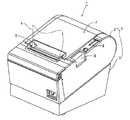
図1は本実施の形態に係るプリンタの外観を示す斜視図である。本実施の形態に係るプリンタ1は、例えば、POSシステムにおいてレシートプリンタとして用いられるものである。 FIG. 1 is a perspective view showing the appearance of the printer according to the present embodiment. The printer 1 according to the present embodiment is used as a receipt printer in a POS system, for example.
プリンタ1は、上ケース2および下ケース3からなる樹脂製の外装ケース4の内部に後述の各構成部分が配置されている。上ケース2の上面は前側が低くなるように傾斜した傾斜面とされ、この上面の前側の部位には記録紙5の排出口6が形成されている。この排出口6よりも後側の上面部分は、開閉カバー7とされている。開閉カバー7は、後端側の部位を中心として開閉可能であり、開閉カバー7の右側に配置されているオープンボタン8(手動操作部材)を押すことにより開けることができる。オープンボタン8の後側の部位には、表示盤9が配置されている。開閉カバー7を全開にすると、記録紙ロール5aの装填部15(図2〜図4参照)が全開状態になり、上側から記録紙ロール5aを当該装填部15に装填することができる。 In the printer 1, each component described later is disposed inside a resin outer case 4 including an upper case 2 and a lower case 3. The upper surface of the upper case 2 is an inclined surface inclined so that the front side is lowered, and a
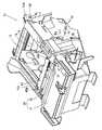
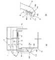
図2および図3は外装ケース4を外してプリンタ内部機構を示す図であり、図2は右側手前から見た場合の斜視図、図3は左側手前から見た場合の斜視図である。また、図4はプリンタ内部機構の概略断面図である。これらの図を参照して説明すると、プリンタ内部機構11は、本体フレーム12と、この本体フレーム12に後端部13aが回転自在に取り付けられたカバーフレーム13とを中心に構成されている。カバーフレーム13の後端部13aは、プリンタ幅方向に延びる開閉中心軸13bを中心に上下方向に開閉可能である。カバーフレーム13には開閉カバー7が取り付けられ、カバーフレーム13の開閉と共に開閉カバー7が開閉する。上ケース2、下ケース3、オープンボタン8及び表示盤9は、本体フレーム12の側に取り付けられている。 2 and 3 are views showing the internal mechanism of the printer with the outer case 4 removed. FIG. 2 is a perspective view when viewed from the right front side, and FIG. 3 is a perspective view when viewed from the left front side. FIG. 4 is a schematic sectional view of the internal mechanism of the printer. Referring to these drawings, the printer
本体フレーム12の後側の部位には湾曲状の樹脂板14が取り付けられ、記録紙ロール5aの装填部15が形成されている。図4に示すように、この装填部15に装填されている記録紙ロール5aから繰り出された記録紙5は、プラテンローラ16とサーマルヘッド17の間を通って上方に搬送される間に、サーマルヘッド17によって印字が行われる。印字後の記録紙5は、排出口6から外部に排出される。サーマルヘッド17は、本体フレーム12の側に支持されている。プラテンローラ16は、カバーフレーム13の前端部に回転自在に取り付けられている。図4に示すように、カバーフレーム13が閉じられた状態では、押圧ばね18によって、サーマルヘッド17がプラテンローラ16に押し付けられた状態が形成される。 A
本体フレーム12の左側の側板部分21の内側には紙送りモータ22が取り付けられて、そのモータ回転軸23の先端部分が側板部分21から外側に突出しており、ここにピニオン24が取り付けられている。ピニオン24は、側板部分21の外側に回転自在に支持されている駆動側複合歯車25に噛み合っている。本例では、紙送りモータ22と駆動側複合歯車25は取り付け板27に取り付けられ、この取り付け板27がねじ28により側板部分21に固定されている。駆動側複合歯車25は、カバーフレーム13の側の従動側歯車26に噛み合っている。従動側歯車26は、カバーフレーム13に搭載されているプラテンローラ16のローラ軸16aの端部に固定されたものである。従って、カバーフレーム13を閉じた状態において、従動側歯車26が駆動側複合歯車25に噛み合った状態が形成され、紙送りモータ22の回転力がプラテンローラ16に伝達可能になる。カバーフレーム13を開けると、従動側歯車26が駆動側複合歯車25から離れる。 A
次に、排出口6の直下には、オートカッターユニット30が配置されている。オートカッターユニット30は、本体フレーム12の側に搭載されている可動刃ユニット31と、カバーフレーム13の前端部の上面に搭載されている固定刃32とを備えている。固定刃32はプリンタ幅方向に延びており、可動刃ユニット31の可動刃31aは、駆動モータ33によって、プリンタ幅方向の一端を中心として固定刃32の側に旋回可能である。可動刃31aを旋回させることにより、印字された記録紙5を切断して、レシートなどとして排出することができる。 Next, an
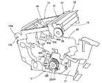
次に、本体フレーム12とカバーフレーム13の間には、閉じ状態にあるカバーフレーム13を本体フレーム12にロックするロック機構40が構成されている。図2〜図6を参照して本例のロック機構40を説明する。図5および図6はプリンタ内部機構11の本体フレーム12およびカバーフレーム13を取り出して示す図であり、図5はカバーフレーム13が半開きの状態を右手前側から見た場合の斜視図、図6はカバーフレーム13が半開きの状態を左手前側から見た場合の斜視図である。 Next, between the
本例のロック機構40は、カバーフレーム13の前端部に搭載されたロック板41(ロック部材)と、本体フレーム12の左側の側板部分21に取り付けたフック42とを備えている。ロック板41は、カバーフレーム13の前端部の上側をプリンタ幅方向に水平に延びている水平板部分43と、水平板部分43の左側の端から下方に直角に折れ曲がって延びているロックレバー44と、水平板部分43の右側の端から下方に直角に折れ曲がって延びているレバー45とを備えている。 The
水平板部分43の左右の端部分には、図3に示すように、プリンタ幅方向に長い長孔43a、43bが形成されている。これらの長孔43a、43bには、カバーフレーム13の前端部に固定された円柱状のガイドピン48a、48bが通されている。従って、これら長孔43a、43bおよびガイドピン48a、48bからなる取り付け部によって、ロック板41はプリンタ幅方向(開閉中心軸13bの中心軸線に平行な方向)に向けて所定の範囲でスライド可能である。本例では、ガイドピン48a、48bとして鍔付ねじ(カップスクリュー)を採用することにより、ロック板41をスライド可能に支持すると共に、ロック板41の上方への抜けを防止している。 As shown in FIG. 3,
また、カバーフレーム13の前端部の右端部分とロック板41の水平板部分43との間には、引張り状態でコイルばね47が架け渡されている。従って、ロック板41は常に右側に偏倚した状態に保持されている。 A
ロック板41のロックレバー44は、カバーフレーム13の左端外側から下方に向けて延びている。このロックレバー44の下端部には、そのプリンタ後側の端面からプリンタ前方に切り欠くことにより形成した凹部51が形成されている。この凹部51は、プリンタ前側に傾斜している傾斜端面部分51aと、この下端に連続して下方に延びる垂直端面部分51bと、この下端からプリンタ後側に直交する方向に延びる水平端面部分51cとによって規定されている。この水平端面部分51cがフック42に係止する係止面として機能する。 The
一方、フック42は、カバーフレーム13の開閉による、ロックレバー44の係止面(水平端面部分)51cよりも下側の先端部分44aの移動軌跡に干渉する位置に配置されている。このフック42は、本体フレーム12の左側の側板部分21から外方に直角に突出した台形形状をしている。本例では、取り付け板27の上端部分を前後方向に折り曲げてフック42を形成している。台形状のフック42は、その上側の端面が、下方に向けて傾斜したガイド面42aとされ、このガイド面42aの下端に連続して下方に垂直に延びる垂直頂面42bが形成され、この垂直頂面42bの下端に連続して下方に向けて傾斜したロックレバー係止面42cが形成されている。 On the other hand, the
次に、図7、図8を参照して、このように構成したロック機構40によるカバーフレーム13をロックする動作を説明する。図7はカバーフレーム13が半開きの状態を示す模式図であり、図8はロック機構40の動作を示すための説明図である。図7に示すようにカバーフレーム13が開いているとする。この状態では、ロック板41はコイルばね47によって右側に偏倚している(図8のAの位置)。カバーフレーム13を閉じると、ロック板41のロックレバー44の先端部分44aが本体フレーム12側のフック42に当たる(図8のBの位置)。カバーフレーム13を更に閉じると、ロックレバー44の先端部分44aがフック42の上側の傾斜したガイド面42aに沿ってフック42に乗り上げながら、コイルばね47のばね力に逆らってロック板41が全体として左側にスライドして、閉じる方向に移動する(図8のCの位置)。ロックレバー44の係止面51cがフック42の垂直頂面42bを越えるまでカバーフレーム13を閉じると、フック42がロックレバー44の凹部51に嵌り込み、ロック板41がばね力によって全体として右側にスライドする。この結果、ロックレバー44の係止面51cが、フック42のロックレバー係止面42cに、下側から係止された状態が形成される(図8のDの位置)。これにより、カバーフレーム13が本体フレーム12にロックされた状態になる。すなわち、カバーフレーム13(開閉カバー7)の閉動作に伴って、ロックレバー44(ロック板41)は矢印Tに示すように移動し、フック42に係止される。 Next, with reference to FIG. 7 and FIG. 8, the operation | movement which locks the
ここで、組み付け誤差や製造誤差などに起因して、カバーフレーム13を完全に閉じた状態の位置が上下に変動した場合には、図9にD1、D2、D3で示すようにフック42に対するロックレバー44の位置が上下に変動する。 Here, when the position of the
しかしながら本例では、ロックレバー44はプリンタ幅方向にスライドしてその凹部51にフック42が嵌め込まれる。従って、ロックレバー44の係止面51cが上下に変動しても、当該係止面51cとフック42のロックレバー係止面42cの角度(係止角度θ)が変化することはない。 However, in this example, the
また、本例では、ロックレバー係止面42cは上方に僅かに傾斜した傾斜面とされている。よって、カバーフレーム13の閉じ状態での位置が上下に変動しても、ロックレバー44の係止面51cが確実にフック42のロックレバー係止面42cに係止される。また、カバーフレーム13の閉じ状態での位置が上側に変動しても、係止角度θが大きくなり係止力が低減してロックが簡単に外れてしまうことはない。 In this example, the lock
次に、本例のプリンタ1における、ロック機構40によるロックを解除するためのロック解除機構について説明する。図1〜図6を参照して説明すると、ロック解除機構60は、前述の手動式のオープンボタン8と、本体フレーム12の右側の側板部分61に配置されている回転式のロック解除レバー62と、ロック板41のレバー45に形成された当接部46を備えている。オープンボタン8はコイルばね等により上方に付勢され、ロック解除レバー62はねじりばね等により反時計回り方向に付勢されて、図2に示す位置に位置している。 Next, a lock release mechanism for releasing the lock by the
ロック解除レバー62は、回転中心軸62aを中心に上下方向に回転可能であり、回転中心軸62aからそれぞれ後方、上方に延出した突起63、64を備えている。突起64(第1の突起)には、側板部分61に接近する方向に傾斜している傾斜面64aが形成されている。オープンボタン8が押し下げられると、オープンボタン8の下側に形成された当接面8aがロック解除レバー62の突起63を下方に押し下げ、これによってロック解除レバー62は時計回りに回転する。ロック解除レバー62が回転すると、突起64の傾斜面64aによってロック板41の当接部46がプリンタ幅方向の内側に向けて押し込まれる。この結果、ロック板41はコイルばね47のばね力に逆らって左側にスライドする。これにより、ロック板41のロックレバー44がフック42から側方に外れた状態になる。 The
また、ロック解除レバー62には、回転中心軸62aから前方に延出した突起65(第2の突起)が形成されている。ロックレバー44がフック42から側方に外れた状態になった後、ロック解除レバー62が更に回転すると、この突起65が下側からカバーフレーム13の下面13cに当たりカバーフレーム13を押し上げる。 Further, the
従って、これらロック板41のスライドとカバーフレーム13の押し上げ動作とによって、ロック機構40によるロックが解除され、カバーフレーム13(開閉カバー7)を開くことができる。 Therefore, the lock by the
(その他の実施の形態)
上記のプリンタ1はサーマルプリンタであるが、インクジェットヘッド、インパクトヘッドなどを備えたプリンタについても本発明を同様に適用可能である。(Other embodiments)
Although the printer 1 is a thermal printer, the present invention can be similarly applied to a printer including an inkjet head, an impact head, and the like.
また、上記の例では、カバーフレームの側にロックレバーをスライド可能に取り付け、本体フレームの側にフックを取り付けているが、カバーフレームの側にフックを取り付け、本体フレームの側にロックレバーをスライド可能に取り付けてもよい。 In the above example, the lock lever is slidably attached to the cover frame side and the hook is attached to the main body frame side. However, the hook is attached to the cover frame side and the lock lever is slid to the main body frame side. It may be attached as possible.
さらには、上記の例では、ロックレバーをスライド可能に構成したが、フックをスライド可能に構成してもよい。 Furthermore, in the above example, the lock lever is slidable, but the hook may be slidable.
また、上記の例では、ロック解除レバー側に傾斜面を形成したが、ロックレバーの当接部に傾斜面を形成してもよいし、双方に傾斜面を形成してもよい。 In the above example, an inclined surface is formed on the lock release lever side. However, an inclined surface may be formed on the contact portion of the lock lever, or an inclined surface may be formed on both sides.
1 プリンタ、4 外装ケース、5 記録紙、5a 記録紙ロール、6 排出口、7 開閉カバー、8 オープンボタン、11 プリンタ内部機構、12 本体フレーム、13 カバーフレーム、13b 開閉中心軸、15 装填部、16 プラテンローラ、17 サーマルヘッド、18 押圧ばね、30 オートカッターユニット、40 ロック機構、41 ロック板、42 フック、42a ガイド面、42c ロックレバー係止面、43 水平板部分、43a、43b 長孔、44 ロックレバー、44a ロックレバーの先端部分、45 レバー、46 当接部、47 コイルばね、48a、48b ガイドピン、51 凹部、51c 係止面、60 ロック解除機構、62 ロック解除レバー、63 突起、64 突起、64a 傾斜面、65 突起
DESCRIPTION OF SYMBOLS 1 Printer, 4 exterior case, 5 recording paper, 5a recording paper roll, 6 discharge port, 7 opening / closing cover, 8 open button, 11 printer internal mechanism, 12 main body frame, 13 cover frame, 13b opening / closing central axis, 15 loading part, 16 Platen roller, 17 Thermal head, 18 Pressure spring, 30 Auto cutter unit, 40 Lock mechanism, 41 Lock plate, 42 Hook, 42a Guide surface, 42c Lock lever locking surface, 43 Horizontal plate portion, 43a, 43b Long hole, 44 Lock lever, 44a Tip of lock lever, 45 lever, 46 contact part, 47 coil spring, 48a, 48b guide pin, 51 recess, 51c locking surface, 60 lock release mechanism, 62 lock release lever, 63 protrusion, 64 protrusions, 64a inclined surface, 65 protrusions
Claims (8)
Translated fromJapanese前記カバーロック機構は、ロックレバー(44)と、前記ロックレバーが係止可能なフック(42)とを備えており、
前記ロックレバーと前記フックの少なくとも一方は、前記カバーフレームの開閉中心軸線にほぼ平行な方向にスライド可能な状態で取り付けられ、前記ロックレバーおよび前記フックは相対的にスライド可能であり、
前記ロックレバーが前記フックに対して第1の方向にスライドして、前記ロックレバーと前記フックの係止状態が形成され、前記ロックレバーが前記フックに対して前記第1の方向とは逆の第2の方向にスライドすると前記ロックレバーと前記フックの係止状態が解除され、
スライド可能な状態で取り付けられた前記ロックレバーまたは前記フックは、付勢部材(47)によって、前記ロックレバーと前記フックの係止状態が形成される方向に付勢され、
前記ロックレバーは、前記カバーフレームが閉じ状態にあるとき前記フックに当接する係止面(51c)であって、前記スライド方向に平行かつ直交する方向に延びるものを備え、
前記フックは、前記カバーフレームの開閉により前記ロックレバーと干渉する位置において、前記スライド方向に突出しており、さらに、
前記フックは、前記カバーフレームが前記閉じ状態の近傍位置に至ると前記ロックレバーに当接するロックレバーガイド面(42a)であって、前記カバーフレームの閉じ状態への移動に伴って、前記ロックレバーを前記フックに対して前記第2の方向に相対的にスライドさせるように傾斜しているものと、前記カバーフレームが前記閉じ状態にあるとき前記ロックレバーに当接するロックレバー係止面(42c)であって、前記第1の方向に向けて前記ロックレバーが位置する方向に所定の角度で傾斜しているものとを備え、
前記ロックレバーは、前記カバーフレームが前記閉じ状態の近傍位置に至ると前記ロックレバーガイド面に当接し、前記カバーフレームの閉じ状態への移動に伴って前記ロックレバーガイド面に沿って前記フックに対して前記第2の方向にスライドし、前記ロックレバーガイド面から外れると前記付勢部材の付勢力によって前記フックに対して前記第1の方向にスライドして、前記ロックレバー係止面に係止された状態になり、
さらに、前記ロックレバーを前記フックに対して前記第2の方向にスライドさせ、前記ロックレバーと前記フックとの係止状態を解除するロック解除機構(60)を備えていることを特徴とするカバーロック機構付きプリンタ。In a printer having a main body frame (12), a cover frame (13) attached to the main body frame so as to be openable and closable, and a cover lock mechanism for locking the cover frame in a closed state to the main body frame ,
The cover lock mechanism includes a lock lever (44) and a hook (42) that can be locked by the lock lever.
At least one of the lock lever and the hook is attached so as to be slidable in a direction substantially parallel to the opening / closing center axis of the cover frame, and the lock lever and the hook are relatively slidable,
The lock lever slides in the first direction with respect to the hook to form a locking state between the lock lever and the hook, and the lock lever is opposite to the hook in the first direction. When sliding in the second direction, the locking state of the lock lever and the hook is released,
The lock lever or the hook attached in a slidable state is urged by an urging member (47) in a direction in which a locking state of the lock lever and the hook is formed,
The lock lever includes a locking surface (51c) that contacts the hook when the cover frame is in a closed state, and extends in a direction parallel to and perpendicular to the sliding direction,
The hook protrudes in the sliding direction at a position where the hook interferes with the lock lever by opening and closing the cover frame, and
The hook is a lock lever guide surface (42a) that comes into contact with the lock lever when the cover frame reaches a position in the vicinity of the closed state, and the lock lever is moved in accordance with the movement of the cover frame to the closed state. And a lock lever engaging surface (42c) that contacts the lock lever when the cover frame is in the closed state. And inclined at a predetermined angle in the direction in which the lock lever is positioned toward the first direction,
The lock lever comes into contact with the lock lever guide surface when the cover frame reaches a position in the vicinity of the closed state, and moves to the hook along the lock lever guide surface as the cover frame moves to the closed state. In contrast, when it slides in the second direction and comes off the lock lever guide surface, it slides in the first direction with respect to the hook by the biasing force of the biasing member, and engages with the lock lever locking surface. Will be stopped,
The cover further comprises a lock release mechanism (60) that slides the lock lever in the second direction with respect to the hook to release the locked state between the lock lever and the hook. Printer with lock mechanism.
前記ロックレバーは前記カバーフレームに配置されており、
前記フックは前記本体フレームに配置されていることを特徴とするカバーロック機構付きプリンタ。In claim 1,
The lock lever is disposed on the cover frame;
The printer with a cover lock mechanism, wherein the hook is disposed on the main body frame.
前記ロックレバーを所定距離だけスライド可能な状態で前記カバーフレームに取り付けている取り付け部(43a、48a、43b、48b)を有し、
前記付勢部材は、前記ロックレバーを前記第1の方向に付勢していることを特徴とするカバーロック機構付きプリンタ。In claim 2,
An attachment portion (43a, 48a, 43b, 48b) for attaching the lock lever to the cover frame in a slidable state by a predetermined distance;
The printer with a cover lock mechanism, wherein the biasing member biases the lock lever in the first direction.
前記ロック解除機構は、
手動操作部材(8)と、
前記手動操作部材を操作すると、前記フックに係止している前記ロックレバーを前記第2の方向にスライドさせるロック解除レバー(62)とを有していることを特徴とするカバーロック機構付きプリンタ。In claim 3,
The unlocking mechanism is
A manual operation member (8);
A printer with a cover lock mechanism, comprising: a lock release lever (62) that slides the lock lever locked to the hook in the second direction when the manual operation member is operated. .
一方の端部に前記ロックレバーを、他方の端部に前記ロック解除レバーと当接可能な当接部(46)を備えたロック部材(41)を有し、
前記ロック解除レバーは第1の突起(64)を備えており、
前記手動操作部材の操作に応じて前記ロック解除レバーが回転することにより、前記第1の突起が、前記ロック部材の前記当接部と当接して、前記ロックレバーを第2の方向にスライドさせることを特徴とするカバーロック機構付きプリンタ。In claim 4,
A lock member (41) having a contact portion (46) capable of contacting the lock lever at one end and the lock release lever at the other end;
The unlocking lever comprises a first protrusion (64);
When the lock release lever rotates according to the operation of the manual operation member, the first protrusion comes into contact with the contact portion of the lock member and slides the lock lever in the second direction. A printer with a cover lock mechanism.
前記ロック部材の前記当接部または前記ロック解除レバーの前記第1の突起のうち少なくとも一方は、前記第2の方向に向けて前記ロック解除レバーの回転方向と反対の方向に傾斜しているガイド面(64a)を備えていることを特徴とするカバーロック機構付きプリンタ。In claim 5,
At least one of the contact portion of the lock member or the first protrusion of the lock release lever is inclined in the direction opposite to the rotation direction of the lock release lever toward the second direction. A printer with a cover lock mechanism, comprising a surface (64a).
前記ロック解除レバーは第2の突起(65)を備え、前記手動操作部材の操作に応じて前記ロック解除レバーが回転することにより、前記第1の突起が、前記ロック部材の前記当接部と当接して、前記ロックレバーを前記第2の方向にスライドさせると共に、前記第2の突起が、前記カバーフレームに下方から当接して、前記カバーフレームを開き方向へ移動させることを特徴とするカバーロック機構付きプリンタ。In claim 5,
The lock release lever includes a second protrusion (65), and the lock release lever rotates in response to an operation of the manual operation member, whereby the first protrusion is brought into contact with the contact portion of the lock member. The cover is abutted to slide the lock lever in the second direction, and the second protrusion abuts the cover frame from below to move the cover frame in the opening direction. Printer with lock mechanism.
前記本体フレームに配置されたサーマルヘッド(17)と、
前記カバーフレームを閉じると前記サーマルヘッドに当接するように、前記カバーフレームの先端部に取り付けたプラテンローラ(16)と、
前記カバーフレームの閉じ状態において、前記サーマルヘッドを前記プラテンローラに押し付け可能な弾性部材(18)とを有していることを特徴とするカバーロック機構付きプリンタ。
In any one of claims 1 to 7,
A thermal head (17) disposed on the body frame;
A platen roller (16) attached to the tip of the cover frame so as to abut against the thermal head when the cover frame is closed;
A printer with a cover lock mechanism, comprising: an elastic member (18) capable of pressing the thermal head against the platen roller in a closed state of the cover frame.
Priority Applications (1)
| Application Number | Priority Date | Filing Date | Title |
|---|---|---|---|
| JP2004015534AJP3823971B2 (en) | 2003-02-03 | 2004-01-23 | Printer with cover lock mechanism |
Applications Claiming Priority (2)
| Application Number | Priority Date | Filing Date | Title |
|---|---|---|---|
| JP2003026152 | 2003-02-03 | ||
| JP2004015534AJP3823971B2 (en) | 2003-02-03 | 2004-01-23 | Printer with cover lock mechanism |
Publications (2)
| Publication Number | Publication Date |
|---|---|
| JP2004255865A JP2004255865A (en) | 2004-09-16 |
| JP3823971B2true JP3823971B2 (en) | 2006-09-20 |
Family
ID=33133620
Family Applications (1)
| Application Number | Title | Priority Date | Filing Date |
|---|---|---|---|
| JP2004015534AExpired - Fee RelatedJP3823971B2 (en) | 2003-02-03 | 2004-01-23 | Printer with cover lock mechanism |
Country Status (1)
| Country | Link |
|---|---|
| JP (1) | JP3823971B2 (en) |
Families Citing this family (4)
| Publication number | Priority date | Publication date | Assignee | Title |
|---|---|---|---|---|
| JP4588647B2 (en)* | 2006-02-18 | 2010-12-01 | エスアイアイ・データサービス株式会社 | Printer and portable terminal device |
| JP6262429B2 (en)* | 2012-12-27 | 2018-01-17 | セイコーインスツル株式会社 | Printer |
| CN108765779A (en)* | 2018-07-02 | 2018-11-06 | 广州洛图终端技术有限公司 | A kind of cap-opening mechanism of concealed quick unlatching one terminating machine |
| US11772395B2 (en) | 2020-10-15 | 2023-10-03 | Zebra Technologies Corporation | Lid subsystem for media processing devices |
- 2004
- 2004-01-23JPJP2004015534Apatent/JP3823971B2/ennot_activeExpired - Fee Related
Also Published As
| Publication number | Publication date |
|---|---|
| JP2004255865A (en) | 2004-09-16 |
Similar Documents
| Publication | Publication Date | Title |
|---|---|---|
| US6758614B2 (en) | Printer unit and printing apparatus incorporating the same | |
| US6916052B2 (en) | Cover locking/unlocking mechanism and a printer having the cover locking/unlocking mechanism | |
| JP3614314B2 (en) | Printer | |
| US7547153B2 (en) | Cutter apparatus and printer provided with cutter apparatus | |
| US20110026999A1 (en) | Cutter mechanism and printer with a cutter | |
| JP2001121764A (en) | Printer | |
| EP1219451B1 (en) | Paper transporting apparatus | |
| JP6313548B2 (en) | Thermal printer | |
| JP6351502B2 (en) | Printing unit and thermal printer | |
| EP2343193B1 (en) | Printer | |
| EP3388241A1 (en) | Head pressing mechanism and tape printing apparatus | |
| JP3823971B2 (en) | Printer with cover lock mechanism | |
| JP5912047B2 (en) | Thermal printer | |
| US8654356B2 (en) | Printer cover opening/closing mechanism, and printer | |
| JP2021154718A (en) | Printing unit and thermal printer | |
| JP6450484B2 (en) | Thermal printer | |
| EP1329328B1 (en) | Printer | |
| CN111070904B (en) | Thermal printer | |
| JP4247251B2 (en) | Thermal printer | |
| JP3622856B2 (en) | Printer | |
| JP2005254620A (en) | Printer | |
| CN1519128A (en) | Printers with a Cover Lock Mechanism | |
| JP3859485B2 (en) | Printer opening / closing mechanism | |
| JP4233976B2 (en) | Vehicle door lock device | |
| JP3696061B2 (en) | Printer |
Legal Events
| Date | Code | Title | Description |
|---|---|---|---|
| A977 | Report on retrieval | Free format text:JAPANESE INTERMEDIATE CODE: A971007 Effective date:20060125 | |
| A131 | Notification of reasons for refusal | Free format text:JAPANESE INTERMEDIATE CODE: A131 Effective date:20060207 | |
| A521 | Request for written amendment filed | Free format text:JAPANESE INTERMEDIATE CODE: A523 Effective date:20060407 | |
| TRDD | Decision of grant or rejection written | ||
| A01 | Written decision to grant a patent or to grant a registration (utility model) | Free format text:JAPANESE INTERMEDIATE CODE: A01 Effective date:20060606 | |
| A61 | First payment of annual fees (during grant procedure) | Free format text:JAPANESE INTERMEDIATE CODE: A61 Effective date:20060619 | |
| R150 | Certificate of patent or registration of utility model | Ref document number:3823971 Country of ref document:JP Free format text:JAPANESE INTERMEDIATE CODE: R150 Free format text:JAPANESE INTERMEDIATE CODE: R150 | |
| FPAY | Renewal fee payment (event date is renewal date of database) | Free format text:PAYMENT UNTIL: 20100707 Year of fee payment:4 | |
| FPAY | Renewal fee payment (event date is renewal date of database) | Free format text:PAYMENT UNTIL: 20110707 Year of fee payment:5 | |
| FPAY | Renewal fee payment (event date is renewal date of database) | Free format text:PAYMENT UNTIL: 20110707 Year of fee payment:5 | |
| FPAY | Renewal fee payment (event date is renewal date of database) | Free format text:PAYMENT UNTIL: 20120707 Year of fee payment:6 | |
| FPAY | Renewal fee payment (event date is renewal date of database) | Free format text:PAYMENT UNTIL: 20120707 Year of fee payment:6 | |
| FPAY | Renewal fee payment (event date is renewal date of database) | Free format text:PAYMENT UNTIL: 20130707 Year of fee payment:7 | |
| S531 | Written request for registration of change of domicile | Free format text:JAPANESE INTERMEDIATE CODE: R313531 | |
| R350 | Written notification of registration of transfer | Free format text:JAPANESE INTERMEDIATE CODE: R350 | |
| LAPS | Cancellation because of no payment of annual fees |