JP3823855B2 - Recording apparatus, reproducing apparatus, recording method, reproducing method, and synchronous reproducing system - Google Patents
Recording apparatus, reproducing apparatus, recording method, reproducing method, and synchronous reproducing systemDownload PDFInfo
- Publication number
- JP3823855B2 JP3823855B2JP2002074374AJP2002074374AJP3823855B2JP 3823855 B2JP3823855 B2JP 3823855B2JP 2002074374 AJP2002074374 AJP 2002074374AJP 2002074374 AJP2002074374 AJP 2002074374AJP 3823855 B2JP3823855 B2JP 3823855B2
- Authority
- JP
- Japan
- Prior art keywords
- data
- audio data
- event
- reproduction
- audio
- Prior art date
- Legal status (The legal status is an assumption and is not a legal conclusion. Google has not performed a legal analysis and makes no representation as to the accuracy of the status listed.)
- Expired - Fee Related
Links
- 230000001360synchronised effectEffects0.000titleclaimsdescription60
- 238000000034methodMethods0.000titleclaimsdescription42
- 230000005236sound signalEffects0.000claimsdescription128
- 238000001514detection methodMethods0.000claimsdescription37
- 238000005259measurementMethods0.000claimsdescription5
- 230000005540biological transmissionEffects0.000claimsdescription2
- 102100040862Dual specificity protein kinase CLK1Human genes0.000description32
- 101000749294Homo sapiens Dual specificity protein kinase CLK1Proteins0.000description32
- 102100040844Dual specificity protein kinase CLK2Human genes0.000description26
- 101000749291Homo sapiens Dual specificity protein kinase CLK2Proteins0.000description26
- 238000010586diagramMethods0.000description23
- 230000006870functionEffects0.000description20
- 238000004891communicationMethods0.000description14
- 238000012986modificationMethods0.000description14
- 230000004048modificationEffects0.000description14
- 238000012545processingMethods0.000description8
- 238000012546transferMethods0.000description3
- 125000002066L-histidyl groupChemical group[H]N1C([H])=NC(C([H])([H])[C@](C(=O)[*])([H])N([H])[H])=C1[H]0.000description2
- 230000010355oscillationEffects0.000description2
- 230000001172regenerating effectEffects0.000description2
- 230000008929regenerationEffects0.000description2
- 238000011069regeneration methodMethods0.000description2
- 230000004044responseEffects0.000description2
- 101100113692Caenorhabditis elegans clk-2 geneProteins0.000description1
- 239000002131composite materialSubstances0.000description1
- 239000013078crystalSubstances0.000description1
- 230000003111delayed effectEffects0.000description1
- 230000000694effectsEffects0.000description1
- 238000005516engineering processMethods0.000description1
- 238000003825pressingMethods0.000description1
- 238000005070samplingMethods0.000description1
Images


Classifications
- G—PHYSICS
- G10—MUSICAL INSTRUMENTS; ACOUSTICS
- G10H—ELECTROPHONIC MUSICAL INSTRUMENTS; INSTRUMENTS IN WHICH THE TONES ARE GENERATED BY ELECTROMECHANICAL MEANS OR ELECTRONIC GENERATORS, OR IN WHICH THE TONES ARE SYNTHESISED FROM A DATA STORE
- G10H1/00—Details of electrophonic musical instruments
- G10H1/0033—Recording/reproducing or transmission of music for electrophonic musical instruments
- G10H1/0041—Recording/reproducing or transmission of music for electrophonic musical instruments in coded form
- G—PHYSICS
- G10—MUSICAL INSTRUMENTS; ACOUSTICS
- G10H—ELECTROPHONIC MUSICAL INSTRUMENTS; INSTRUMENTS IN WHICH THE TONES ARE GENERATED BY ELECTROMECHANICAL MEANS OR ELECTRONIC GENERATORS, OR IN WHICH THE TONES ARE SYNTHESISED FROM A DATA STORE
- G10H2240/00—Data organisation or data communication aspects, specifically adapted for electrophonic musical tools or instruments
- G10H2240/011—Files or data streams containing coded musical information, e.g. for transmission
- G10H2240/031—File merging MIDI, i.e. merging or mixing a MIDI-like file or stream with a non-MIDI file or stream, e.g. audio or video
- G—PHYSICS
- G10—MUSICAL INSTRUMENTS; ACOUSTICS
- G10H—ELECTROPHONIC MUSICAL INSTRUMENTS; INSTRUMENTS IN WHICH THE TONES ARE GENERATED BY ELECTROMECHANICAL MEANS OR ELECTRONIC GENERATORS, OR IN WHICH THE TONES ARE SYNTHESISED FROM A DATA STORE
- G10H2240/00—Data organisation or data communication aspects, specifically adapted for electrophonic musical tools or instruments
- G10H2240/011—Files or data streams containing coded musical information, e.g. for transmission
- G10H2240/046—File format, i.e. specific or non-standard musical file format used in or adapted for electrophonic musical instruments, e.g. in wavetables
- G10H2240/056—MIDI or other note-oriented file format
Landscapes
- Physics & Mathematics (AREA)
- Engineering & Computer Science (AREA)
- Acoustics & Sound (AREA)
- Multimedia (AREA)
- Electrophonic Musical Instruments (AREA)
- Signal Processing For Digital Recording And Reproducing (AREA)
Description
Translated fromJapanese【0001】
【発明の属する技術分野】
本発明は、CD(Compact Disc)等の記憶媒体に記憶された楽曲の再生に同期してMIDI(Musical Instrument Digital Interface)等に準拠した楽曲データの記録若しくは再生を行うを行う記録装置、再生装置、記録方法、再生方法及び同期再生システムに関する。
【0002】
【従来の技術】
楽曲を再生するための手段として、コンパクトディスク(CD)などの記憶媒体から楽曲データである時系列オーディオデータを読み出し、音として出力する装置がある。また、別の形態の楽曲再生手段として、楽曲データの一種であるMIDI(Musical Instrument Digital Interface)データをフロッピーディスク(FD)などの記憶媒体から読み出し、このMIDIデータに従って音源を駆動し、自動演奏を行う装置がある。そして、最近では、これらの複合形態、すなわち、CD等の記憶媒体に格納されている楽曲のオーディオデータの再生に同期して、FD等の記憶媒体に格納されているMIDIデータを読み出し、自動演奏をする技術が提案されるに至っている。
【0003】
ところで、オーディオデータとMIDIデータとを別々の記憶媒体、例えばCDとFDから読み出して1つのまとまった楽曲を再生するためには、オーディオデータをCDから読み出して音として出力するオーディオデータ再生装置の動作と、MIDIデータをFDから読み出して自動演奏を行うMIDIデータ再生装置の動作とを同期させる必要がある。ここで、CD等の記憶媒体に記憶されている楽曲データには、該時系列オーディオデータのほか、楽曲の開始からの経過時間を示すタイムコードが含まれている。このCDに格納されているタイムコードをオーディオデータ再生装置からMIDIデータ再生装置へ順次供給させることができれば、MIDIデータ再生装置は当該時点におけるオーディオデータの演奏箇所を把握することができ、該演奏箇所に対応するMIDIデータを再生する等により、オーディオデータの再生と同期を保った状態でMIDIデータを再生することが可能となる。
【0004】
【発明が解決しようとする課題】
しかしながら、現在、一般家庭などにおいて広く利用されているオーディオデータ再生装置の大部分は、タイムコードを装置外部に出力する機能(以下、タイムコード出力機能)を備えていない。いいかえれば、オーディオデータ再生装置の大部分は、CDから読み出したタイムコードを装置外部(MIDIデータ再生装置等)へ供給することができず、このため、上記のように該オーディオデータ再生装置によるオーディオデータの再生と同期を保った状態でMIDIデータを再生することが極めて難しいという問題があった。
この種の問題は、該オーディオデータの再生と同期を保った状態でMIDIデータを再生する場合に限らず、該オーディオデータの再生と同期を保った状態でMIDIデータを記録する場合、例えば該オーディオデータの再生に併せてユーザが自動ピアノ演奏等を行い、このピアノ演奏音をMIDIデータとしてFD等に記録する場合等にも生じていた。
【0005】
本発明は、以上説明した事情を鑑みてなされたものであり、CD等の記憶媒体に記録されているオーディオデータを再生する装置として、タイムコード出力機能を備えていないオーディオデータ再生装置を使用した場合であっても、該オーディオデータの再生に同期してMIDIデータの記録若しくは再生することができる記録装置、再生装置、記録方法、再生方法及び同期再生システムを提供することを目的とする。
【0006】
【課題を解決するための手段】
以上説明した課題を解決するため、本発明は、オーディオデータ再生装置によるオーディオデータの再生に同期して、複数のイベントと各イベントの実行タイミングを指定するタイミングデータとを含む楽曲データを記憶媒体に記録する記録装置であって、前記オーディオデータ再生装置から前記オーディオデータの再生に基づき生成されるオーディオ信号を入力する入力手段と、前記オーディオ信号のピークを検出したとき、時間管理用のイベントを生成する第1イベント生成手段と、楽器の操作状態を検出する検出手段から該操作状態を取得し、取得した該操作状態に応じて楽曲の演奏制御を指示するイベントを生成する第2イベント生成手段と、クロックをカウントすることにより計時を行う計時手段と、前記計時手段による計時結果に基づいて、前記タイミングデータを生成するタイミングデータ生成手段と、前記第1イベント生成手段によって生成される時間管理用のイベントと、前記第2イベント生成手段によって生成される楽曲の演奏制御を指示するイベントと、前記タイミングデータ生成手段によって生成されるタイミングデータとを含む楽曲データを前記記憶媒体に記録する記録手段とを具備することを特徴とする。
【0007】
かかる構成によれば、記録装置は、楽器の操作状態に応じて楽曲の演奏制御を指示するイベントを生成する一方、オーディオデータ再生装置から供給されるオーディオ信号の信号レベルが閾値レベルを越えたとき、時間管理用のイベントを生成する。そして、これら楽曲の演奏制御を指示するイベントと、時間管理用のイベントと、各イベントの実行タイミング指定するタイミングデータとを含む楽曲データが記憶媒体に記録される。かかる記憶媒体に記録された楽曲データを、オーディオデータ再生装置によるオーディオデータの再生に同期して再生する場合、閾値レベルを超えるオーディオ信号が検出されるタイミングに応じて、該時間管理用のイベントを読み出すタイミングを制御することで、オーディオデータの再生と楽曲データの再生との同期を保つことが可能となる。
【0008】
また、本発明は、オーディオデータ再生装置によるオーディオデータの再生に同期して、記憶媒体に記録された楽曲データを再生する再生装置であって、該記憶媒体に記録された楽曲データは、前記オーディオデータ再生装置によるオーディオデータの再生に同期して記録された楽曲データであり、前記オーディオデータ再生装置から前記オーディオデータの再生に基づき生成されるオーディオ信号を入力する入力手段と、前記オーディオ信号のピークを検出したとき、該記憶媒体に記録された楽曲データの再生を開始する再生制御手段とを具備することを特徴とする。
【0009】
かかる構成によれば、再生装置は、前記楽曲データを該オーディオデータの再生に同期して再生する場合、オーディオデータ再生装置から供給されるオーディオ信号の信号レベルが閾値レベルを越えたことを検出したとき、楽曲データの再生を開始する。このように、閾値レベルを越えるオーディオ信号の検出を該楽曲データの再生トリガとして利用することで、オーディオデータの再生と楽曲データの再生との同期を保つことが可能となる。
【0010】
また、本発明は、オーディオデータ再生装置によるオーディオデータの再生に同期して、記憶媒体に記録された楽曲データを再生する再生装置であって、該記憶媒体に記録された楽曲データは、前記オーディオデータ再生装置によるオーディオデータの再生に同期して記録された複数のイベントと各イベントの実行タイミングを指定するタイミングデータとを含む楽曲データであり、前記複数のイベントは、前記オーディオデータの再生に基づき生成されるオーディオ信号のピークの検出タイミングを示す時間管理用のイベントと楽曲の演奏制御を指示するイベントとを含み、前記オーディオデータ再生装置から前記オーディオデータの再生に基づき生成されるオーディオ信号を入力する入力手段と、前記オーディオ信号のピークを検出する検出手段と、クロックをカウントすることにより計時を行う計時手段による計時結果に基づき、前記楽曲データ中のタイミングデータによって定まる時刻に、対応するイベントを読み出すイベント読み出し手段と、前記イベント読み出し手段によって読み出された複数のイベントのうち、楽曲演奏制御を指示するイベントを再生手段に供給する制御手段と、前記イベント読み出し手段によって前記時間管理用のイベントが読み出されるタイミングと、前記検出手段によって前記オーディオ信号のピークが検出されるタイミングとのずれに応じて、前記イベント読み出し手段による前記楽曲演奏制御を指示するイベントの読み出しタイミングを調整する調整手段とを具備することを特徴とする。
【0011】
かかる構成によれば、再生装置は、オーディオデータ再生装置から供給されるオーディオ信号の信号レベルが閾値レベルを超えたことを検出する検出タイミングと、時間管理用のイベントを読み出す読み出しタイミングのずれに応じて、楽曲演奏制御を指示するイベントを読み出すタイミングを調整する。例えば、該検出タイミングが、該読み出しタイミングよりも遅い場合には、イベントの読み出しタイミングを遅らせる。この結果、オーディオデータの再生と楽曲データの再生との同期を保つことが可能となる。
【0012】
【発明の実施の形態】
A.本実施形態
(1)実施形態の構成
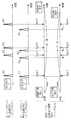
図1は、本実施形態に係る同期記録再生システムSSの構成を示す図である。
同期記録再生システムSSは、CDからオーディオデータを読み出し、オーディオ信号として出力する一般的な(すなわち、上記タイムコード出力機能を備えていない)オーディオデータ再生装置ARと、ケーブル等により該オーディオデータ再生装置ARと接続され、該オーディオデータの再生に同期してFDにMIDIデータを記録し、若しくは該FDに記録されているMIDIデータを再生するMIDIデータ記録再生装置MRとを具備している。
【0013】
本発明は、このようにオーディオデータ再生装置としてタイムコード出力機能を備えていない一般的なオーディオデータ再生装置ARを利用し、該オーディオデータ再生装置ARによるオーディオデータの再生と、MIDIデータ記録再生装置MRによるMIDIデータの記録・再生等との同期を図る点に特徴がある。以下、オーディオデータ再生装置AR及びMIDIデータ記録再生装置MRの詳細構成について説明する。
【0014】
<オーディオデータ再生装置AR>
オーディオデータ再生装置ARは、装着されたCDから記録データを読み出し、オーディオ信号を生成して出力する装置である。
このオーディオデータ再生装置ARは、図示せぬ操作部から入力される指示に従って、CDに記録されているオーディオデータを読み出し、オーディオ信号を生成し、生成したオーディオ信号をケーブルを介してMIDIデータ記録再生装置MRへ順次出力する。ここで、該CDに記録されているオーディオデータは、所定周波数(44.1kHz等)のサンプリングクロックによりサンプリングされた時系列オーディオデータである。従って、オーディオデータ再生装置ARは、周波数を該所定周波数に設定したクロックをオーディオデータ再生用のクロック(以下、クロックCLK1という)として利用し、オーディオデータの読み出し動作等を行う。
【0015】
<MIDIデータ記録再生装置MR>
MIDIデータ記録再生装置MRは、上記オーディオデータ再生装置ARによるCDの再生に併せてユーザが自動ピアノ20を演奏したときの演奏音をMIDIデータとしてFD(Floppy Disk)に記録する一方、該CDの再生に併せてFDに記録されたMIDIデータを再生する装置である。
【0016】
通信インタフェース2は、オーディオデータ再生装置ARと当該MIDIデータ記録再生装置MRとの通信を制御する手段であり、オーディオデータ再生装置ARからケーブルを介して供給されるオーディオ信号をコントローラ3へ供給する役割を担っている。なお、本実施形態では、オーディオデータ再生装置ARとMIDIデータ記録再生装置MRとを有線ケーブルによって接続する場合を例示するが、例えばBluetooth、IrDA(Infrared Data Association)、HomeRF(Home Radio Frequency)などを利用して無線接続しても良いのは勿論である。
【0017】
コントローラ3は、CPU、ROM、RAM等により構成され、ROMに格納されている各種制御プログラムに従ってMIDIデータ記録再生装置MR全体を制御するほか、オーディオデータ再生装置ARから供給されるオーディオ信号を順次ミキサ5へ供給し、音として出力させるための制御や、該オーディオ信号の信号レベルを検出し、検出結果に応じて後述する時間管理用のイベントを生成する処理(以下、信号レベル検出処理)等を行う。
【0018】
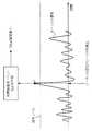
図2は、コントローラ3によって実行される信号レベル検出処理を示すフローチャートである。
コントローラ3は、オーディオデータ再生装置ARから通信インタフェース2を介して順次供給されるオーディオ信号を受信すると(ステップS1)、このオーディオ信号を順次ミキサ5へ供給し、音として出力させるための制御を行うと共に、該オーディオ信号の信号レベルの検出を行う(ステップS2)。具体的には、コントローラ3は、入力されるオーディオ信号の信号レベルと予めRAM等に設定されている閾値レベルとの比較を行い、該オーディオ信号の信号レベルが閾値レベルを超えたか否か、すなわちオーディオ信号のピークを検出したかどうかを判断する。
【0019】
コントローラ3は、図3に示すようにオーディオ信号の信号レベルが閾値レベルを越えたことを検出(すなわち、オーディオ信号のピークPを検出)すると(ステップS2;YES)、ステップS3に進み、MIDIデータ記録時であるか、あるいはMIDIデータ再生時であるかを判断する。コントローラ3は、MIDIデータの記録時であると判断すると、ステップS4へ進み、時間管理用のイベントを生成し、生成した時間管理用のイベントをFD記録装置8へ供給して処理を終了する。
【0020】
一方、コントローラ3は、MIDIデータの記録時であると判断すると、ステップS5へ進み、オーディオ信号のピークを検出した旨をFD再生装置8aへ通知し、処理を終了する。なお、かかる時間管理用のイベントは、オーディオデータの再生に同期してMIDIデータを再生する際に、オーディオデータの再生位置とMIDIデータの再生位置との間に生じたずれを検出するために利用される。この時間管理用のイベントを利用して上記ずれを検出する方法等については、後述する。
【0021】
図1に戻り、自動ピアノ20は、ユーザによる鍵操作に応じて打弦による機械的なピアノ音や電子的なピアノ音を発生する楽音発生機能を備えるほか、ユーザによる鍵操作を検出し、検出結果に応じてMIDIイベントを生成し、これをFDに記録させる機能や、FDに記録されたMIDIデータに従って自動演奏を行うを備えている。
【0022】
かかる自動ピアノ20は、ピアノ11と、キーセンサ12と、ペダルセンサ13と、MIDIイベント生成回路14と、ピアノ音源15と、ピアノ電子回路16と、アンサンブル音源18とを有している。
キーセンサ12及びペダルセンサ13は、それぞれピアノ11に配設された複数の鍵及び複数のペダル(ソステヌートペダル等)の各々に対応して設けられ、鍵及びペダルを押したときの強さ、深さなどを検出し、検出した鍵若しくはペダルを特定するキー番号若しくはペダル番号、ベロシティー情報(押鍵強度等に対応したデータ)等を含む検出結果をMIDIイベント生成回路14に供給する。
【0023】
MIDIイベント生成回路14は、コントローラ3による制御の下、キーセンサ12及びペダルセンサ13から供給される検出結果に基づいてMIDIイベントを生成する。ここで、MIDIイベントは、図4に示すように、発音又は消音すべき旨を示すノートオン・ノートオフ情報と、発音すべき音の高さを示すノートナンバ情報と、発音の強弱を示すベロシティ情報等によって構成されている。MIDIイベント生成回路14は、上記検出結果に基づいて、例えば「ドの音(ノートナンバ)を強さ10(ベロシティ)で発音(ノートオン)せよ」といった演奏制御を指示するイベントの一種であるMIDIイベントを生成し、かかるMIDIイベントをコントローラ3及びピアノ音源15に供給する。
【0024】
ピアノ音源15は、MIDIイベント生成回路14から供給されるイベントにより指示されたピアノ音のオーディオ信号を電子的に生成する装置である。このピアノ音源15により生成されたオーディオ信号は、ミキサ5へ出力される。
ミキサ5は、ピアノ音源15から出力されるオーディオ信号と、オーディオデータ再生装置ARから通信インタフェース2、コントローラ3を介して供給されるオーディオ信号等を混合して出力する装置である。このミキサ5の出力信号は、アンプ6によって増幅され、スピーカ7から音として出力される。
【0025】
アンサンブル音源18は、コントローラ3からイベントを受け取り、そのイベントに従ってデジタル楽音信号を生成する装置である。このアンサンブル音源18により生成されたデジタル楽音信号は、ミキサ5に送られる。
ミキサ5は、コントローラ3、ピアノ音源15、アンサンブル音源18等から出力される各信号を混合して出力する装置である。このミキサ5の出力信号は、アンプ6によって増幅され、スピーカ7から音として出力される。
【0026】
ピアノ電子回路16は、コントローラ3からイベントを受け取り、自動演奏のための制御を行う回路である。このピアノ電子回路16は、2通りの方法のうちいずれかにより自動演奏の制御を行う。まず、第1の方法では、コントローラ3から受け取ったイベントをピアノ音源15に送る。前述したように、ピアノ音源15は、イベントにより指示されたピアノ音のオーディオ信号を電子的に生成する装置である。
【0027】
第2の方法では、ピアノ電子回路16は、コントローラ3から受け取ったイベントに従って駆動ソレノイド群17に対する通電制御を行う。この駆動ソレノイド群17は、ピアノ11に設けられた複数の鍵に各々対応した複数のソレノイドと、複数のペダルに各々対応した複数のソレノイドとからなる。ピアノ電子回路16は、ある鍵の押下を指示するイベントをコントローラ3から受け取った場合、その鍵に対応したソレノイドに駆動電流を流し、鍵を押下させるのに必要な磁力をソレノイドにより発生する。離鍵を指示するイベントを受け取った場合も同様である。第1の方法、第2の方法のいずれによりイベントを取り扱うかの指示は、操作部4からコントローラ3に与えられ、コントローラ3はこの指示をピアノ電子回路16に送る。ピアノ電子回路16は、受け取った指示に従う。
【0028】
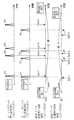
FD記録装置8は、CDの再生に併せてユーザが自動ピアノ20を演奏したときの演奏音、すなわちユーザによる自動ピアノ20の演奏音をFD(Floppy Disk)に記録する装置であり、コントローラ3による制御の下、MIDIイベント等を含むSMF(Standard MIDI File)を作成する機能を有している。ここで、SMFは、図5に示すように、ヘッダチャンクHTとトラックチャンクTTによって構成されている。ヘッダチャンクHTには、SMFの基本的な情報(チャンクタイプ等)が格納され、トラックチャンクTTには、MIDIデータが格納される。MIDIデータは、同図に示すように、演奏制御等を指示するイベントと、先行するイベントと後発のイベントとの発生時間間隔を示すデルタタイムからなる時系列の楽曲データである。ここで、MIDIデータを構成するイベントは、MIDIイベント生成回路14において生成されるMIDIイベントや、上述したコントローラ3において生成される時間管理用のイベント等によって構成されている。
【0029】
かかるFD記録装置8は、コントローラ3内のクロック生成手段33によって生成されるMIDIデータ記録・再生用のクロック(以下、クロックCLK2という)をカウントすることにより計時を行う計時手段(図示略)を備え、該計時手段による計時結果に基づいて、上述したデルタタイムの生成を行う。
【0030】
FD再生装置8aは、コントローラ3からの指令に従い、FDに記録されているMIDIデータを順次読み出してコントローラ3に供給する。このMIDIデータは、例えばFD記録装置8によりCDの再生に同期して記録されたMIDIデータである(図5参照)。FD再生装置8aは、あるイベントをFDから読み出してコントローラ3に送った後は、そのイベントの後のデルタタイムによって示される時間だけ待機し、後続のイベントの読み出しを行う、という処理を繰り返す。これがFD再生装置8aの基本的な動作である。
【0031】
かかるFD再生装置8aは、FD記録装置8と同様、上記クロック生成手段33によって生成されるクロックCLK2をカウントすることにより計時を行う計時手段(図示略)を備え、該計時手段による計時結果と各デルタタイムに示される時間とを比較することにより、対応するイベントの読み出しタイミングを制御する。ここで、FD記録装置8によりCDの再生に同期して記録された1曲分のMIDIデータには、演奏制御用のMIDIイベントの他、時間管理用のイベントが含まれている。FD再生装置8aは、以上説明したMIDIデータをFDから読み出す機能(すなわち、シーケンサとしての機能)の他に、この時間管理用のイベントを利用して、オーディオデータ再生装置ARによるオーディオデータの再生とMIDIデータ記録再生装置MRによるMIDIデータの再生の同期を維持する機能を有している。なお、かかる機能の詳細については、動作説明の項において明らかにする。
【0032】
以上説明したFD記録装置8によるMIDIデータの記録及びFD再生装置8aによるMIDIデータの再生は、上記説明から明らかなように、いずれもコントローラ3内のクロック生成手段33によって生成されるクロックCLK2に基づいて行われる。なお、コントローラ3内に設けられたクロック生成手段33は、水晶振動子とアンプとにより構成された発振回路(いずれも図示略)を備えており、該発振回路から出力される発信信号を適宜分周してタイミング制御用の各種のクロック(本発明に特に関連の深いクロックは、上述したクロックCLK2である)を生成する。以下、本実施形態に係る同期記録再生システムSSの動作について説明する。
【0033】
(2)実施形態の動作
a.第1の動作例
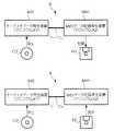
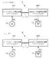
図6及び図7は、第1の動作例を説明するための図である。なお、以下では、クロックCLK1を利用してオーディオデータの再生を行うオーディオデータ再生装置AR1と、クロックCLK2を利用してMIDIデータの記録及び再生を行うMIDIデータ記録再生装置MR1を例に説明を行う。
ユーザは、まずオーディオデータ再生装置AR1とMIDIデータ記録再生装置MR1とをケーブルによって接続する(図6参照)。そして、ユーザはMIDIデータ記録再生装置MR1の操作部4を操作して、FDに対するMIDIデータの記録を待機すべき旨の入力(図7に示す、録音待機指示参照)を行った後、オーディオデータ再生装置AR1の操作部(図示略)等を操作して、CDに格納されているオーディオデータの再生を開始すべき旨の入力(図7に示す、再生指示参照)を行う。
【0034】
オーディオデータ再生装置AR1の制御部(図示略)は、操作部からオーディオデータの再生開始指示を受け取ると、クロックCLK1を利用してオーディオデータの読み出しを開始する。そして、制御部は、この読み出したオーディオデータからオーディオ信号を生成し、MIDIデータ記録再生装置MR1に順次供給していく。
【0035】
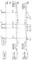
MIDIデータ記録再生装置MR1のコントローラ3は、オーディオデータ再生装置AR1から通信インタフェース2等を介してオーディオ信号を受け取ると、前掲図2に示すオーディオ信号検出処理を実行し、オーディオデータ再生装置AR1から供給されるオーディオ信号を順次ミキサ5へ供給して音として出力させるための制御を行うと共に、該オーディオ信号の信号レベルの検出を開始する。そして、コントローラ3は、入力されるオーディオ信号のピークP1(図7参照)を検出すると、時間管理用のイベントSys−1を生成し、これをFD記録装置8へ送出する(図2に示す、ステップS3→ステップS4)。そして、コントローラ3は、該FD記録装置8へMIDIデータの記録を開始すべき指令を送出する。
【0036】
かかる指令を受け取ると、FD記録装置8は、クロック生成手段33から供給されるクロックCLK2を利用して、FDに対するMIDIデータの記録を開始する。そして、操作部4等を介して記録を終了すべき旨が入力(図7に示す、録音終了指示参照)されると、コントローラ3は、MIDIデータの記録終了指示をFD記録装置8へ送出し、FDに対するMIDIデータの記録を終了させる。
【0037】
その後、ユーザはMIDIデータ記録再生装置MR1の操作部4を操作して、FDに記録されたMIDIデータの再生を待機すべき旨の入力(図7に示す、再生待機指示参照)を行った後、オーディオデータ再生装置AR1の操作部(図示略)等を操作して、CDに格納されているオーディオデータの再生を開始すべき旨の入力(図7に示す、再生指示参照)を行う。
オーディオデータ再生装置AR1の制御部(図示略)は、操作部からオーディオデータの再生開始指示を受け取ると、クロックCLK1を利用してオーディオデータの読み出しを開始する。そして、制御部は、この読み出したオーディオデータからオーディオ信号を生成し、MIDIデータ記録再生装置MR1に順次供給していく。
【0038】
MIDIデータ記録再生装置MR1のコントローラ3は、オーディオデータ再生装置AR1から通信インタフェース2等を介してオーディオ信号を受け取ると、前掲図2に示すオーディオ信号検出処理を実行し、オーディオデータ再生装置AR1から供給されるオーディオ信号を順次ミキサ5へ供給して音として出力させるための制御を行うと共に、該オーディオ信号の信号レベルの検出を開始する。そして、コントローラ3は、入力されるオーディオ信号のピークP1を検出すると、該ピークP1を検出した旨をFD再生装置8aへ通知する(図2に示す、ステップS3→ステップS5)。そして、コントローラ3は、該FD再生装置8aへFDに記録されているMIDIデータの再生を開始すべき指令を送出する。
【0039】
かかる指令を受け取ると、FD再生装置8aは、クロック生成手段33から供給されるクロックCLK2を利用して、FDに記録されているMIDIデータの再生を開始する。具体的には、まずFDに記録されている時間管理用のイベントSys−1(図7参照)を読み出し、その後にFDに記録されている種々のイベント(MIDIイベント等)を読み出すことによりMIDIデータを再生する。前述したように、FD記録装置8によるMIDIデータの記録及びFD再生装置8aによるMIDIデータの再生は、いずれもクロック生成手段33によって生成されるクロックCLK2に基づいて行われる。また、オーディオデータの再生は、MIDIデータの記録時及びMIDIデータの再生時のいずれにおいても、クロックCLK1に基づいて行われる。
【0040】
従って、オーディオ信号のピークP1が検出された時点でMIDIデータの記録を開始若しくは再生を開始すれば、オーディオデータとMIDIデータとを同期を保った状態で再生することが可能となる。なお、かかるピークP1を検出する際には、オーディオデータに対応した音のボリューム調整が必要となる。すなわち、MIDIデータの記録時とMIDIデータ再生時との間で、基準となる音のボリュームを変更した場合には(例えば、該ボリュームを「2」から「4」へ変更)、オーディオ信号のピーク検出位置にずれが生じてしまうことが予想される。従って、かかるピークを検出する際には、オーディオ信号のピーク検出位置にずれが生じないように該ボリュームを一定に、或いはボリュームの調整を制限する等の措置を施せば良い。
【0041】
b.第2の動作例
以上説明した第1の動作例では、オーディオ信号のピークを1回のみ(すなわち、最初のピークのみ)検出する場合を例に説明した。これに対し、以下に示す第2〜第4の動作例では、オーディオ信号のピークを数回(例えば、1曲分のオーディオデータの再生を開始してから終了するまで)検出する場合を例に説明を行う。
図8及び図9は、第2の動作例を説明するための図である。なお、以下では、クロックCLK1を利用してオーディオデータの再生を行うオーディオデータ再生装置AR1と、クロックCLK1よりも周波数が高いクロックCLK1’を利用してオーディオデータの再生を行うオーディオデータ再生装置AR2と、クロックCLK2を利用してMIDIデータの記録及び再生を行うMIDIデータ記録再生装置MR1を例に説明を行う。
【0042】
ユーザは、まずオーディオデータ再生装置AR1とMIDIデータ記録再生装置MR1とをケーブルによって接続する(図8に示すA参照)。その後、ユーザは、MIDIデータ記録再生装置MR1の操作部4を操作して、FDに対するMIDIデータの記録を待機すべき旨の入力(図9に示す、録音待機指示参照)を行った後、オーディオデータ再生装置AR1の操作部(図示略)等を操作して、CDに格納されているオーディオデータの再生を開始すべき旨の入力(図9に示す、再生指示1参照)を行う。
【0043】
オーディオデータ再生装置AR1の制御部(図示略)は、操作部からオーディオデータの再生開始指示を受け取ると、クロックCLK1を利用してオーディオデータの読み出しを開始する。そして、制御部は、この読み出したオーディオデータからオーディオ信号を生成し、MIDIデータ記録再生装置MR1に順次供給していく。
【0044】
MIDIデータ記録再生装置MR1のコントローラ3は、オーディオデータ再生装置AR1から通信インタフェース2等を介してオーディオ信号を受け取ると、図10に示すオーディオ信号検出処理を実行する。この図10に示す信号レベル検出処理は、図2に示す信号レベル検出処理に対してステップS6を追加した処理である。従って対応するステップには同一符号を付し、説明を省略する。
【0045】
コントローラ3は、オーディオデータ再生装置AR1から供給されるオーディオ信号を順次ミキサ5へ供給して音として出力させるための制御を行うと共に、該オーディオ信号の信号レベルの検出を開始する。そして、コントローラ3は、入力されるオーディオ信号のピークP1(図9参照)を検出すると、時間管理用のイベントSys−1を生成し、これをFD記録装置8へ送出する(図10に示す、ステップS3→ステップS4)。そして、コントローラ3は、該FD記録装置8へMIDIデータの記録を開始すべき指令を送出する。
【0046】
かかる指令を受け取ると、FD記録装置8は、クロック生成手段33から供給されるクロックCLK2を利用して、FDに対するMIDIデータの記録を開始する。一方、コントローラ3は、FD記録装置8へMIDIデータの記録を開始すべき指令等を送出すると、ステップS6へ進み、例えば操作部4等を介して記録を終了すべき旨の入力があったかどうかを検出する。コントローラ3は、記録を終了すべき旨の入力がなく、MIDIデータの記録を継続すべきであると判断すると(ステップS6;YES)、ステップS1に戻り、上述した処理を繰り返し実行する。
【0047】
そして、コントローラ3は、例えば図9に示すようにオーディオ信号のピークP2〜Pnを検出し、これらオーディオ信号のピークP2〜Pnに対応する時間管理用のイベントSys−2〜Sys−nの生成等を行った後に、記録を終了すべき旨の入力(図10に示す、録音終了指示参照)を検出すると(ステップS6;NO)、MIDIデータの記録終了指示をFD記録装置8へ送出し、FDに対するMIDIデータの記録を終了させる。
【0048】
この結果、第1の動作例では、FDに時間管理用のイベントが1つ(図7に示す、時間管理用のイベントSys−1)のみ記録されたのに対し、第2の動作例では、FDに時間管理用のイベントが複数(図9に示す、時間管理用のイベントSys−1〜Sys−n)が記録される。
【0049】
MIDIデータの記録が終了すると、ユーザはMIDIデータ記録再生装置MR1に接続されているオーディオデータ再生装置AR1を外し、該オーディオデータ再生装置AR1とは異なるオーディオデータ再生装置AR2をMIDIデータ記録再生装置MR1に接続する(図8に示すB参照)。
その後、ユーザはMIDIデータ記録再生装置MR1の操作部4を操作して、FDに記録されたMIDIデータの再生を待機すべき旨の入力(図9に示す、再生待機指示参照)を行った後、オーディオデータ再生装置AR2の操作部(図示略)等を操作して、CDに格納されているオーディオデータの再生を開始すべき旨の入力を行う。
【0050】
オーディオデータ再生装置AR2の制御部(図示略)は、操作部からオーディオデータの再生開始指示を受け取ると、クロックCLK1よりも周波数が高いクロックCLK1’を利用して、オーディオデータの読み出しを開始する。そして、制御部は、この読み出したオーディオデータからオーディオ信号を生成し、MIDIデータ記録再生装置MR1に順次供給していく。
【0051】
MIDIデータ記録再生装置MR1のコントローラ3は、オーディオデータ再生装置AR2から通信インタフェース2等を介してオーディオ信号を受け取ると、前掲図10に示すオーディオ信号検出処理を実行する。ここで、オーディオデータ再生装置AR2のクロックCLK1’の周波数は、オーディオデータ再生装置AR1のクロックCLK1の周波数よりも高いため、オーディオ信号のピークが検出される時刻は、オーディオデータ再生装置AR1を利用した場合よりも、オーディオデータ再生装置AR2を利用した場合の方がはやくなる。
【0052】
コントローラ3は、このオーディオ信号のピークP1を検出すると、上記第1の動作例と同様、該ピークP1を検出した旨をFD再生装置8aへ通知する(図10に示す、ステップS3→ステップS5)。そして、コントローラ3は、該FDに記録されているMIDIデータの再生を開始すべき指令を送出する。
【0053】
かかる指令を受け取ると、FD再生装置8aは、クロック生成手段33から供給されるクロックCLK2を利用して、FDに記録されているMIDIデータの再生を開始する。具体的には、まずFDに記録されている時間管理用のイベントSys−1を読み出し、その後にFDに記録されている種々のイベント(MIDIイベント等)を読み出すことによりMIDIデータを再生する。一方、コントローラ3は、FD再生装置8aへMIDIデータの再生を開始すべき指令等を送出すると、ステップS6へ進み、例えば操作部4等を介して再生を終了すべき旨の入力があったかどうかを検出する。コントローラ3は、再生を終了すべき旨の入力がなく、MIDIデータの再生を継続すべきであると判断すると(ステップS6;YES)、ステップS1に戻り、上述した処理を繰り返し実行する。
【0054】
この結果、コントローラ3がオーディオ信号のピークを検出する度に、該ピークを検出した旨がコントローラ3からFD再生装置8aへ通知される。前述したように、MIDIデータ再生時におけるオーディオデータの読み出しは、クロックCLK1よりも周波数が高いクロックCLK1’を利用して行われる。従って、該MIDIデータ再生時におけるオーディオデータの読み出し速度は、クロックCLK1を利用してオーディオデータの読み出しを行うMIDIデータ記録時よりも速くなる。具体的には、図9に示す時間管理用のイベントSys−2を読み出す前に、該時間管理用のイベントSys−2に対応するオーディオ信号のピークP2を検出した旨の通知が、コントローラ3からFD再生装置8aへ行われることとなる。
【0055】
FD再生装置8aは、コントローラ3から該オーディオ信号のピークP2を検出した旨の通知を受け取ってから、時間管理用のイベントSys−2を所定時間内に読み出した場合には、何もしない。一方、FD再生装置8aは、コントローラ3から該オーディオ信号のピークを検出した旨の通知を受け取ってから、時間管理用のイベントSys−2を所定時間内に読み出すことができない場合には、例えば後続のMIDIイベントを所定個数読み飛ばし、読み飛ばした後のMIDIイベント等から読み出しを開始する。
【0056】
この結果、オーディオデータの再生速度が、MIDIデータの再生速度よりも速い場合においても、オーディオデータの再生とMIDIデータの再生の同期は保たれることになる。なお、オーディオ信号のピークP3〜Pnに対応する時間管理用のイベントSys−3〜Sys−nについては、時間管理用のイベントSys−2と同様に説明することができるため、説明を割愛する。また、オーディオデータの再生速度が、MIDIデータの再生速度よりも遅い場合については、本動作例の論理によってほぼ同様に説明することができるため、説明を割愛する。
【0057】
このように、第2の動作例では、オーディオデータの再生に同期してMIDIデータを記録する際、オーディオデータの再生によって得られるオーディオ信号のピークを複数検出し、検出したピークP1〜Pnに対応する時間管理用のイベントSys−1〜Sys−nをFDに記録する。そして、該オーディオデータの再生に同期してMIDIデータを再生する際、オーディオ信号のピークが検出されるタイミングと、上記時間管理用のイベントSys−1〜Sys−nが読み出されるタイミングのずれに応じて、MIDIイベント等の読み出しタイミングを調整する。これにより、オーディオデータとMIDIデータとを同期を保った状態で再生することが可能となる。
【0058】
c.第3の動作例
図11及び図12は、第3の動作例を説明するための図である。なお、以下では、クロックCLK1を利用してオーディオデータの再生を行うオーディオデータ再生装置AR1と、クロックCLK2を利用してMIDIデータの記録及び再生を行うMIDIデータ記録再生装置MR1と、クロックCLK2よりも周波数が高いクロックCLK2’を利用してMIDIデータの記録及び再生を行うMIDIデータ記録再生装置MR2を例に説明する。
【0059】
ユーザは、まずオーディオデータ再生装置AR1とMIDIデータ記録再生装置MR1とをケーブルによって接続する(図11に示すA参照)。その後、ユーザは、MIDIデータ記録再生装置MR1の操作部4を操作して、FDに対するMIDIデータの記録を待機すべき旨の入力(図12に示す、録音待機指示参照)を行った後、オーディオデータ再生装置AR1の操作部(図示略)等を操作して、CDに格納されているオーディオデータの再生を開始すべき旨の入力(図12に示す、再生指示参照)を行う。
【0060】
オーディオデータ再生装置AR1の制御部(図示略)は、操作部からオーディオデータの再生開始指示を受け取ると、クロックCLK1を利用してオーディオデータの読み出しを開始する。そして、制御部は、この読み出したオーディオデータからオーディオ信号を生成し、MIDIデータ記録再生装置MR1に順次供給していく。
【0061】
MIDIデータ記録再生装置MR1のコントローラ3は、オーディオデータ再生装置AR1から通信インタフェース2等を介してオーディオ信号を受け取ると、前掲図10に示すオーディオ信号検出処理を実行する。この結果、FDには、コントローラ3によって検出されるオーディオ信号の各ピークP1〜Pnに対応する複数の時間管理用のイベントSys−1〜Sys−nが記録される。なお、オーディオ信号のピーク検出及び時間管理用のイベント記録に関する詳細については、上述した第2の動作例と同様に説明することができるため、割愛する。
【0062】
さて、MIDIデータの記録が終了すると、ユーザはオーディオデータ再生装置AR1に接続されているMIDIデータ記録再生装置MR1を外し、該MIDIデータ記録再生装置MR1とは異なるMIDIデータ記録再生装置MR2を該オーディオデータ再生装置AR1に接続する(図11に示すB参照)。
その後、ユーザはMIDIデータ記録再生装置MR2の操作部4を操作して、FDに記録されたMIDIデータの再生を待機すべき旨の入力(図12に示す、再生待機指示参照)を行った後、オーディオデータ再生装置AR1の操作部(図示略)等を操作して、CDに格納されているオーディオデータの再生を開始すべき旨の入力(図12に示す、再生指示参照)を行う。
【0063】
オーディオデータ再生装置AR1の制御部(図示略)は、操作部からオーディオデータの再生開始指示を受け取ると、クロックCLK1を利用して、オーディオデータの読み出しを開始する。そして、制御部は、この読み出したオーディオデータからオーディオ信号を生成し、MIDIデータ記録再生装置MR2に順次供給していく。
【0064】
MIDIデータ記録再生装置MR2のコントローラ3は、オーディオデータ再生装置AR1から通信インタフェース2等を介してオーディオ信号を受け取ると、前掲図10に示すオーディオ信号検出処理を実行する。
【0065】
コントローラ3は、このオーディオ信号のピークP1を検出すると、上記第1の動作例と同様、該ピークP1を検出した旨をFD再生装置8aへ通知する(図10に示す、ステップS3→ステップS5)。そして、コントローラ3は、該FDに記録されているMIDIデータの再生を開始すべき指令を送出する。
【0066】
かかる指令を受け取ると、FD再生装置8aは、クロック生成手段33から供給されるクロックCLK2’を利用して、FDに記録されているMIDIデータの再生を開始する。ここで、MIDIデータ記録再生装置MR2のクロックCLK2’の周波数は、MIDIデータ記録再生装置MR1のクロックCLK2よりも高いため、時間管理用のイベントSys−2〜Sys−nが読み出される時刻は、MIDIデータ記録再生装置MR1を利用した場合よりも、MIDIデータ記録再生装置MR2を利用した場合の方がはやくなる。換言すれば、MIDIデータ再生時におけるMIDIデータの読み出しは、クロックCLK2よりも周波数が高いクロックCLK2’を利用して行われるため、該MIDIデータ再生時におけるMIDIデータの読み出し速度は、クロックCLK2を利用してMIDIデータの読み出しを行うMIDIデータ記録時よりも速くなる。
【0067】
この結果、FD再生装置8aは、例えば時間管理用のイベントSys−2を読み出した後に、該時間管理用のイベントSys−2に対応するオーディオ信号のピークP2を検出した旨の通知をコントローラ3から受け取ることになる。
【0068】
FD再生装置8aは、時間管理用のイベントSys−2を読み出してから、所定時間内にコントローラ3から該オーディオ信号のピークP2を検出した旨の通知を受け取った場合には、何もしない。一方、FD再生装置8aは、時間管理用のイベントSys−2を読み出してから、所定時間内にコントローラ3から該オーディオ信号のピークP2を検出した旨の通知を受け取ることができなかった場合には、例えば時間管理用のイベントSys−2を読み出してからコントローラ3から該オーディオ信号のピークP2を検出した旨の通知を受け取るまでの時間を計時し、この時間に相当する時間データを後続のデルタタイムに加算する等の処理を行う。
【0069】
この結果、MIDIデータ記録時及び再生時においてオーディオデータの再生速度が一定であり、かつ、MIDIデータの再生速度がMIDIデータの記録速度よりも速い場合においても、オーディオデータの再生とMIDIデータの再生の同期は保たれることになる。なお、オーディオ信号のピークP3〜Pnに対応する時間管理用のイベントSys−3〜Sys−nについては、時間管理用のイベントSys−2と同様に説明することができるため、説明を割愛する。また、MIDIデータ再生速度が、MIDIデータの記録速度よりも遅い場合については、本動作例の論理によってほぼ同様に説明することができるため、説明を割愛する。
【0070】
このように、第3の動作例では、オーディオデータの再生に同期してMIDIデータを記録する際、オーディオデータの再生によって得られるオーディオ信号のピークを複数検出し、検出したピークP1〜Pnに対応する時間管理用のイベントSys−1〜Sys−nをFDに記録する。そして、該オーディオデータの再生に同期してMIDIデータを再生する際、オーディオ信号のピークが検出されるタイミングと、上記時間管理用のイベントSys−1〜Sys−nが読み出されるタイミングのずれに応じて、MIDIイベント等の読み出しタイミングを調整する。これにより、オーディオデータとMIDIデータとを同期を保った状態で再生することが可能となる。
【0071】
d.第4の動作例
図13及び図14は、第4の動作例を説明するための図である。なお、以下では、クロックCLK1を利用してオーディオデータの再生を行うオーディオデータ再生装置AR1と、クロックCLK1よりも周波数が高いクロックCLK1’を利用してオーディオデータの再生を行うオーディオデータ再生装置AR2と、クロックCLK2を利用してMIDIデータの記録及び再生を行うMIDIデータ記録再生装置MR1と、クロックCLK2よりも周波数が高いクロックCLK2’を利用してMIDIデータの記録及び再生を行うMIDIデータ記録再生装置MR2を例に説明する。また、以下の説明では、例えばレコード会社がオーディオデータ再生装置AR1とMIDIデータ記録再生装置MR1を所有し、ユーザがオーディオデータ再生装置AR2とMIDIデータ記録再生装置MR2を所有している場合を想定する(図13参照)。
【0072】
レコード会社で働く従業員等は、まずオーディオデータ再生装置AR1とMIDIデータ記録再生装置MR1とをケーブルによって接続する(図13に示すA参照)。その後、該従業員等は、MIDIデータ記録再生装置MR1の操作部4を操作して、FDに対するMIDIデータの記録を待機すべき旨の入力(図14に示す、録音待機指示参照)を行った後、オーディオデータ再生装置AR1の操作部(図示略)等を操作して、CDに格納されているオーディオデータの再生を開始すべき旨の入力(図14に示す、再生指示1参照)を行う。
【0073】
オーディオデータ再生装置AR1の制御部(図示略)は、操作部からオーディオデータの再生開始指示を受け取ると、クロックCLK1を利用してオーディオデータの読み出しを開始する。そして、制御部は、この読み出したオーディオデータからオーディオ信号を生成し、MIDIデータ記録再生装置MR1に順次供給していく。
【0074】
MIDIデータ記録再生装置MR1のコントローラ3は、オーディオデータ再生装置AR1から通信インタフェース2等を介してオーディオ信号を受け取ると、前掲図10に示すオーディオ信号検出処理を実行する。この結果、FDには、コントローラ3によって検出されるオーディオ信号の各ピークP1〜Pnに対応する複数の時間管理用のイベントSys−1〜Sys−nが記録される。なお、オーディオ信号のピーク検出及び時間管理用のイベント記録に関する詳細については、上述した第2の動作例と同様に説明することができるため、割愛する。
【0075】
さて、MIDIデータの記録が終了すると、レコード会社は、上記オーディオデータの記録されたCD及び上記MIDIデータの記録されたFDをユーザ等に販売する。ユーザは、楽器店等にて該CD及びFDを購入すると、これらを自己のオーディオデータ再生装置AR2及びMIDIデータ記録再生装置MR2にそれぞれ装着する(図13に示すB参照)。
【0076】
その後、ユーザはMIDIデータ記録再生装置MR2の操作部4を操作して、FDに記録されたMIDIデータの再生を待機すべき旨の入力(図14に示す、再生待機指示参照)を行った後、オーディオデータ再生装置AR2の操作部(図示略)等を操作して、CDに格納されているオーディオデータの再生を開始すべき旨の入力(図14に示す、再生指示2参照)を行う。
【0077】
オーディオデータ再生装置AR2の制御部(図示略)は、操作部からオーディオデータの再生開始指示を受け取ると、クロックCLK1’を利用して、オーディオデータの読み出しを開始する。そして、制御部は、この読み出したオーディオデータからオーディオ信号を生成し、MIDIデータ記録再生装置MR2に順次供給していく。
【0078】
MIDIデータ記録再生装置MR2のコントローラ3は、オーディオデータ再生装置AR2から通信インタフェース2等を介してオーディオ信号を受け取ると、前掲図10に示すオーディオ信号検出処理を実行する。ここで、オーディオデータ再生装置AR2(ユーザ側)のクロックCLK1’の周波数は、オーディオデータ再生装置AR1(レコード会社側)のクロックCLK1の周波数よりも高いため、オーディオ信号のピークが検出される時刻は、オーディオデータ再生装置AR1を利用した場合よりも、オーディオデータ再生装置AR2を利用した場合の方がはやくなる。
【0079】
コントローラ3は、このオーディオ信号のピークP1を検出すると、上記各動作例と同様、ピークP1を検出した旨をFD再生装置8aへ通知する(図10に示す、ステップS3→ステップS5)。そして、コントローラ3は、該FDに記録されているMIDIデータの再生を開始すべき指令を送出する。
【0080】
かかる指令を受け取ると、FD再生装置8aは、クロック生成手段33から供給されるクロックCLK2’を利用して、FDに記録されているMIDIデータの再生を開始する。前述したように、MIDIデータ記録再生装置MR2(ユーザ側)のクロックCLK2’の周波数は、MIDIデータ記録再生装置MR1(レコード会社側)のクロックCLK2よりも高いため、時間管理用のイベントSys−2〜Sys−nが読み出される時刻は、MIDIデータ記録再生装置MR1を利用した場合よりも、MIDIデータ記録再生装置MR2を利用した場合の方がはやくなる。
【0081】
ここで、FD再生装置8aは、例えば図14に示すようにオーディオ信号のピークP2を検出した旨の通知を受け取る前に、時間管理用のイベントSys−2を読み出した場合、該時間管理用のイベントSys−2を読み出してから、該オーディオ信号のピークP2を検出した旨の通知を所定時間内に受け取った場合には、何もしない。一方、FD再生装置8aは、時間管理用のイベントSys−2を読み出してから、該オーディオ信号のピークP2を検出した旨の通知を所定時間内に受け取ることができなかった場合には、例えば時間管理用のイベントSys−2を読み出してからコントローラ3から該オーディオ信号のピークP2を検出した旨の通知を受け取るまでにかかった時間に相当する時間データを後続のデルタタイムに加算する等の処理を行う。
【0082】
この結果、MIDIデータ記録時及び再生時においてオーディオデータの再生速度が異なり、かつ、MIDIデータの記録速度及び再生速度が異なる場合においても、オーディオデータの再生とMIDIデータの再生の同期は保たれることになる。なお、オーディオ信号のピークP3〜Pnに対応する時間管理用のイベントSys−3〜Sys−nについては、時間管理用のイベントSys−2と同様に説明することができるため、説明を割愛する。また、MIDIデータ再生時におけるオーディオデータの再生速度が、MIDIデータ記録時におけるオーディオデータの再生速度よりも遅い場合及びMIDIデータの再生速度が、MIDIデータの記録速度よりも遅い場合等については、本動作例の論理によってほぼ同様に説明することができるため、説明を割愛する。
【0083】
このように、第4の動作例では、MIDIデータ記録時に使用したオーディオデータ再生装置及びMIDIデータ記録再生装置と、MIDIデータ再生時に使用したオーディオデータ再生装置及びMIDIデータ記録再生装置とが、それぞれ異なる装置であっても、オーディオデータとMIDIデータとを同期を保った状態で再生することが可能となる。
【0084】
以上説明したように、本実施形態に係るMIDIデータ記録再生装置MRによれば、一般家庭などにおいて広く利用されているタイムコード出力機能を備えていないオーディオデータ再生装置によるオーディオデータの再生に同期して、MIDIデータを記録することができ、さらに、該オーディオデータの再生に同期して、記録したMIDIデータを再生することができる。
【0085】
B.変形例
以上この発明の一実施形態について説明したが、上記実施形態はあくまで例示であり、上記実施形態に対しては、本発明の趣旨から逸脱しない範囲で様々な変形を加えることができる。変形例としては、例えば以下のようなものが考えられる。
【0086】
<変形例1>
上述した本実施形態に第4の動作例では、レコード会社がCDに記録されたオーディオデータの再生に同期してFDにMIDIデータを記録し、これらを販売する一方、ユーザが楽器店等において該CD及び該FDを購入し、該CDに記録されたオーディオデータの再生に同期してFDに記録されたMIDIデータを再生する場合について説明した。これに対し、以下に示す変形例1では、レコード会社がネットワークを介して上記オーディオデータ及びMIDIデータをユーザに送信する一方、ユーザがレコード会社から受信したオーディオデータの再生に同期してMIDIデータを再生する場合について説明を行う。
【0087】
図15は、変形例1に係る同期記録再生システムSS’の構成を示す図である。
同期記録再生システムSS’は、オーディオデータ及び該オーディオデータの再生に同期して記録したMIDIデータ(以下、同期記録MIDIデータという)を提供するコンテンツ・サーバCSと、インターネットや固定電話網など様々な通信網によって構成されるネットワークNWと、該ネットワークNWを介し、コンテンツ・サーバCSから上記オーディオデータ及びMIDIデータを受信することが可能な複数のクライアント端末CTとを具備している。なお、図15では、図面が煩雑になるのを防ぐため、クライアント端末CTを1台のみ図示している。
【0088】
コンテンツ・サーバCSは、レコード会社が所有する種々のサーバソフトウェアを搭載したコンピュータであり、複数のオーディオデータと複数の同期記録MIDIデータとを対応付けて格納したデータ・ベース部DBを備えている。
図16は、オーディオデータ及び同期記録MIDIデータの構成を説明するための図である。オーディオデータ及び同期記録MIDIデータは、それぞれヘッダとペイロードにより構成されている。オーディオデータのヘッダには、該オーディオデータを識別するための識別情報(オーディオ−ID)が含まれ、オーディオデータのペイロードには、オーディオ信号を生成するためのデータが含まれている。同期記録MIDIデータもオーディオデータとほぼ同様、該同期記録MIDIデータのヘッダには、該同期記録MIDIデータを識別するための識別情報(MIDI−ID)が含まれ、同期記録MIDIデータのペイロードには、演奏制御等を指示するMIDIイベントや時間管理用のイベント、デルタタイム等が含まれている。
【0089】
以上説明したデータベース部DBに格納されている複数のオーディオデータ及び同期記録MIDIデータは、それぞれオーディオデータ再生装置AR1(第4の動作例参照)によって再生されるオーディオデータ及び該オーディオデータの再生に同期してMIDIデータ記録再生装置MR1(第4の動作例参照)によって記録されるMIDIデータである。かかるコンテンツ・サーバCSは、クライアント端末CTからネットワークNWを介して所定のオーディオデータ及び同期記録MIDIデータの配信要求を受信すると、対応するオーディオデータ及び同期記録MIDIデータをネットワークNWを経由で該クライアント端末CT宛に送信する。
【0090】
クライアント端末CTは、例えばユーザが所有するパーソナルコンピュータ等であり、ネットワークNWに接続された種々のサーバとの間でデータ等を授受するための機能(ネットワーク接続機能)や、上記コンテンツ・サーバCSから受信したオーディオデータ及び同期記録MIDIデータを、ケーブル等により当該クライアント端末CTに接続されたオーディオデータ再生装置AR2(第4の動作例参照)及びMIDIデータ記録再生装置MR2(第4の動作例参照)へそれぞれ送信する機能を備えている。
【0091】
かかる同期記録再生システムSS’を利用する場合、ユーザは、まずクライアント端末CTの操作部(図示略)等を操作し、上記コンテンツ・サーバCSを指定するURL(Uniform Resource Locator)、IPアドレス等を入力して該コンテンツ・サーバCSのアクセスを試みる。コンテンツ・サーバCSは、クライアント端末CSからネットワークNWを介してアクセス要求を受け取ると、該要求に応じ、データベース部DBに格納されている複数のオーディオデータ及び複数の同期記録MIDIデータをリスト形式で表示するためのリスト情報を図示せぬ記憶手段から読み出し、これをクライアント端末CS宛に送信する。
【0092】
クライアント端末CSは、コンテンツ・サーバCSからネットワークNW経由で受信したリスト情報をディスプレイ(図示略)に表示する。ユーザは、該ディスプレイに表示されるリスト情報を参照し、配信を要求すべきオーディオデータ及び同期記録MIDIデータを決定する。そして、ユーザは操作部を操作し、決定したオーディオデータ及び同期記録MIDIデータを配信すべき旨の入力を行う。かかる入力が行われると、クライアント端末CTは、コンテンツ・サーバCSに対し、該オーディオデータ及び同期記録MIDIデータの配信要求を行う。
【0093】
コンテンツ・サーバCSは、ネットワーク経由で該配信要求を受け取ると、データベース部DBから対応するオーディオデータ及び同期記録MIDIデータを読み出し、これをクライアント端末CT宛に送信する。
クライアント端末CTは、コンテンツ・サーバCSからオーディオデータ及び同期記録MIDIデータを受信すると、自端末に接続されたオーディオ再生装置AR2及びMIDIデータ記録再生装置MR2へ転送する。なお、転送する際、クライアント端末CTは、該オーディオデータ及び同期記録MIDIデータのヘッダに含まれている識別情報を参照し、いずれのデータをいずれの装置に送信すべきかを判断する。
【0094】
一方、オーディオデータ再生装置AR2及びMIDIデータ記録再生装置MR2は、それぞれクライアント端末CTから受信したオーディオデータ及び同期記録MIDIデータを、揮発性メモリや不揮発性メモリ等によって構成された記憶手段に格納する。
【0095】
その後、オーディオデータ再生装置AR2に記憶されたオーディオデータの再生に同期して、MIDIデータ記録再生装置MR2に記憶された同期記録MIDIデータを再生することを試みるユーザは、まずオーディオデータ再生装置AR2とMIDIデータ記録再生装置MR2とをケーブル等によって接続する。そして、ユーザは、MIDIデータ記録再生装置MR2の操作部4を操作して、記憶手段に記憶されている同期記録MIDIデータの再生を待機すべき旨の入力を行った後、オーディオデータ再生装置AR2の操作部等を操作して、記憶手段に記憶されているオーディオデータの再生を開始すべき旨の入力を行う。かかる入力が行われると、オーディオデータ再生装置AR2及びMIDIデータ記録再生装置MR2は、第4の動作例と同様の処理を行う。この結果、第4の動作例と同様に、該オーディオデータと同期記録MIDIデータが同期を保った状態で再生される。なお、オーディオデータ再生装置AR2及びMIDIデータ記録再生装置MR2の動作に関する詳細は、第4の動作例とほぼ同様に説明することができるため、割愛する。
【0096】
なお、本変形例では、クライアント端末CTがコンテンツ・サーバCSからオーディオデータ及び同期記録MIDIデータを受信し、当該クライアント端末CTに接続されたオーディオデータ再生装置AR2及びMIDIデータ記録再生装置MR2にそれぞれ転送する場合を例に説明したが、例えばオーディオデータ再生装置AR2及びMIDIデータ記録再生装置MR2にそれぞれネットワーク接続機能が搭載されている場合には、コンテンツ・サーバCSから送信されるオーディオデータ及び同期記録MIDIデータを直接受信するようにしても良い。
【0097】
また、本変形例では、クライアント端末CTがコンテンツ・サーバCSからオーディオデータ及び同期記録MIDIデータを受信した場合、クライアント端末CTは、受信した各データを自端末に接続されたオーディオ再生装置AR2及びMIDIデータ記録再生装置MR2に転送する構成であったが、クライアント端末が各データを受信した時点において、オーディオデータ再生装置AR2及びMIDIデータ記録再生装置MR2が自端末に接続されていないことも想定される。かかる場合を想定し、クライアント端末CTがコンテンツ・サーバCSからオーディオデータ及び同期記録MIDIデータを受信した場合には、一旦ハードディスク(図示略)等に格納し、その後、クライアント端末CTにオーディオデータ再生装置AR2及びMIDIデータ記録再生装置MR2された場合に、ハードディスク等に格納された各データをオーディオデータ再生装置AR2及びMIDIデータ記録再生装置MR2に送信するようにしても良い。
【0098】
また、本変形例では、クライアント端末CTとしてパーソナルコンピュータ等を例示したが、上記ネットワーク接続機能やオーディオデータ再生装置AR2及びMIDIデータ記録再生装置MR2との間でデータの授受を行うための機能を搭載した様々な端末(例えば、携帯電話、PHS(Personal Handyphone System)、PDA(Personal Digital Assistance)等)に適用可能である。
また、例えばレコード会社がCDをユーザ等に販売する一方、該CDに記録されたオーディオデータの再生に同期して著名な演奏者等が演奏した演奏データを同期記録MIDIデータとして複数記録し、これを上記データベース部DBに格納する。ユーザは、該データベースDBにアクセスし、格納されている複数の同期記録MIDIデータの中から、自分の好みの演奏者(例えば、演奏者α等)に対応する同期記録MIDIデータをダウンロードする。このように本変形例を上述した本実施形態に適用することも可能である。
【0099】
<変形例2>
図17は、変形例2に係るマスターCDに記録されたオーディオデータを説明するための図である。
マスターCDは、例えばレコード会社(上述した第4の動作例参照)等において作成されるCDである。このマスターCDに記録されているオーディオデータを所定のオーディオデータ再生装置AR1を用いて再生することで、オーディオ信号のピークP1〜Pnが所定時間間隔ΔT1で検出されるようになっている。なお、以下の説明では、オーディオデータ再生装置AR1におけるオーディオデータ再生用のクロックをCLK1とする。
【0100】
オーディオデータ再生装置AR2及びMIDIデータ記録再生装置MRを所有するユーザは、上記マスターCDを楽器店等において購入し、これを該オーディオデータ再生装置AR2に装着する。そして、ユーザは、オーディオデータ再生装置AR2とMIDIデータ記録再生装置MRとをケーブル等によって接続し、オーディオデータ再生装置AR2の操作部(図示略)を操作して、CDに記録されたオーディオデータの再生指示を行う。
【0101】
オーディオデータ再生装置AR2は、かかる再生指示に従い、クロックCLK1’を利用して、オーディオデータの読み出し動作を開始する。一方、MIDIデータ記録再生装置MRは、オーディオデータ再生装置AR2から供給されるオーディオ信号のピーク検出を開始する。MIDIデータ記録再生装置MRは、該ピークが検出される時間間隔(以下、時間間隔ΔT2とする)を図示せぬRAM等に記録し、これを上述した時間間隔ΔT1と比較することにより、オーディオデータ再生装置AR2のクロックCLK1’とオーディオ再生装置AR1のクロックCLK1のずれ及びクロックCLK1’の周波数を把握する。MIDIデータ記録再生装置MRは、把握したオーディオデータ再生装置AR2のクロックCLK1’に基づき、MIDIデータの記録速度、再生速度を調整することで、オーディオデータの再生とMIDIデータの記録若しくは再生を同期させることが可能となる。
【0102】
なお、上記オーディオデータが記録されているマスターCDの代わりに、該オーディオデータを配信するサーバを設け、ネットワーク(インターネット等)経由でアクセスのあったユーザに対して、該オーディオデータを無償等でダウンロードするようにしても良い。
【0103】
ここで、上述した本実施形態では、オーディオデータを記憶する記憶媒体としてCDを例示したが、FD、MD、オーディオテープ、レコードなど、オーディオデータを記憶することができる様々な記憶媒体に適用可能である。また、MIDIデータを記憶する記憶媒体についても、上記と同様、様々な記憶媒体(CD、MD等)に適用可能である。
【0104】
また、本発明は、FD記録装置8、FD再生装置8a、コントローラ3など、図1に示すMIDIデータ記録再生装置MRに係る全ての構成要素を含んだ自動ピアノを製造し、販売するという態様でも実施され得る。かかる態様によれば、ユーザは、該自動ピアノと、一般的なオーディオデータ再生装置(すなわち、タイムコード出力機能を備えていないオーディオデータ再生装置)とを用いて、CDに記録されたオーディオデータの再生に同期して演奏データ(例えば、ユーザがピアノ11を演奏することにより得られる演奏データ等)をFDに記録することができると共に、FDに記録された該演奏データに基づく自動演奏に同期させてCDに記録されたオーディオデータの再生を行うことができる。
【0105】
【発明の効果】
以上説明したように本発明によれば、CD等の記憶媒体に記録されているオーディオデータを再生する装置として、タイムコード出力機能を備えていないオーディオデータ再生装置を使用した場合であっても、該オーディオデータの再生に同期してMIDIデータの記録、再生等を行うことができる。
【図面の簡単な説明】
【図1】 本実施形態における同期記録システムの構成を示す図である。
【図2】 同実施形態に係る信号レベル検出処理を示すフローチャートである。
【図3】 同実施形態に係るオーディオ信号を説明するための図である。
【図4】 同実施形態に係るMIDIイベントの構成を示す図である。
【図5】 同実施形態に係るSMFの構成を示す図である。
【図6】 同実施形態における第1の動作例を説明するための図である。
【図7】 同実施形態における第1の動作例を説明するための図である。
【図8】 同実施形態における第2の動作例を説明するための図である。
【図9】 同実施形態における第2の動作例を説明するための図である。
【図10】 同実施形態における第2の動作例に係る信号レベル検出処理を示すフローチャートである。
【図11】 同実施形態における第3の動作例を説明するための図である。
【図12】 同実施形態における第3の動作例を説明するための図である。
【図13】 同実施形態における第4の動作例を説明するための図である。
【図14】 同実施形態における第4の動作例を説明するための図である。
【図15】 変形例1に係る同期記録システムの構成を示す図である。
【図16】 変形例1に係るオーディオデータ及び同期記録MIDIデータの構成を説明するための図である。
【図17】 変形例2に係るマスターCDに記録されたオーディオデータを説明するための図である。
【符号の説明】
AR・・・オーディオデータ再生装置、MR・・・MIDIデータ記録再生装置、2・・・通信インタフェース、3・・・コントローラ、4・・・操作部、5・・・ミキサ、6・・・アンプ、7・・・スピーカ、8・・・FD記録装置、8a・・・FD再生装置、20・・・自動ピアノ、11・・・ピアノ、12・・・キーセンサ、13・・・ペダルセンサ、14・・・MIDIイベント生成回路、15・・・ピアノ音源、16・・・ピアノ電子回路、17・・・駆動ソレノイド群、18・・・アンサンブル音源、33・・・クロック生成手段。[0001]
BACKGROUND OF THE INVENTION
The present invention relates to a recording apparatus and a reproducing apparatus for recording or reproducing music data compliant with MIDI (Musical Instrument Digital Interface) or the like in synchronization with reproduction of music stored in a storage medium such as a CD (Compact Disc). The present invention relates to a recording method, a reproduction method, and a synchronous reproduction system.
[0002]
[Prior art]
As means for reproducing music, there is a device that reads time-series audio data, which is music data, from a storage medium such as a compact disc (CD) and outputs it as sound. As another form of music playback means, MIDI (Musical Instrument Digital Interface) data, which is a kind of music data, is read from a storage medium such as a floppy disk (FD), and the sound source is driven according to the MIDI data to perform automatic performance. There is a device to do. Recently, in synchronization with the reproduction of these composite forms, that is, audio data of music stored in a storage medium such as a CD, the MIDI data stored in the storage medium such as an FD is read and automatically played. Technology has been proposed.
[0003]
By the way, in order to read audio data and MIDI data from separate storage media, for example, CD and FD and reproduce a single piece of music, the operation of an audio data reproducing apparatus that reads audio data from a CD and outputs it as sound. It is necessary to synchronize the operation of the MIDI data reproducing apparatus that reads out MIDI data from the FD and performs automatic performance. Here, in addition to the time-series audio data, the music data stored in a storage medium such as a CD includes a time code indicating an elapsed time from the start of the music. If the time code stored in the CD can be sequentially supplied from the audio data reproducing apparatus to the MIDI data reproducing apparatus, the MIDI data reproducing apparatus can grasp the performance position of the audio data at the time, and the performance position. The MIDI data can be reproduced in a state in which the data is synchronized with the reproduction of the audio data.
[0004]
[Problems to be solved by the invention]
However, most of the audio data playback apparatuses that are currently widely used in general homes and the like do not have a function of outputting a time code to the outside of the apparatus (hereinafter referred to as a time code output function). In other words, most of the audio data reproducing apparatus cannot supply the time code read from the CD to the outside of the apparatus (such as a MIDI data reproducing apparatus). For this reason, the audio data by the audio data reproducing apparatus as described above is used. There is a problem that it is extremely difficult to reproduce MIDI data in a state in which data reproduction and synchronization are maintained.
This type of problem is not limited to the case where MIDI data is reproduced while being synchronized with the reproduction of the audio data, but when MIDI data is recorded while being synchronized with the reproduction of the audio data, for example, the audio data This also occurs when the user performs an automatic piano performance or the like in conjunction with the data reproduction and records the piano performance sound as MIDI data on an FD or the like.
[0005]
The present invention has been made in view of the above-described circumstances, and an audio data reproducing apparatus that does not have a time code output function is used as an apparatus for reproducing audio data recorded on a storage medium such as a CD. Even if it is a case, it aims at providing the recording apparatus, reproducing | regenerating apparatus, recording method, reproducing | regenerating method, and synchronous reproduction | regeneration system which can record or reproduce | regenerate MIDI data synchronizing with reproduction | regeneration of this audio data.
[0006]
[Means for Solving the Problems]
In order to solve the problems described above, the present invention provides music data including a plurality of events and timing data for specifying the execution timing of each event in a storage medium in synchronization with the reproduction of audio data by the audio data reproducing device. A recording device for recording, wherein an input means for inputting an audio signal generated based on reproduction of the audio data from the audio data reproducing device, and an event for time management when a peak of the audio signal is detected A first event generating means for acquiring the operating state from a detecting means for detecting an operating state of the musical instrument, and a second event generating means for generating an event for instructing performance control of the music according to the acquired operating state; , Clocking means for counting time by counting clocks, and clocking results by the clocking means Based on timing data generating means for generating the timing data, an event for time management generated by the first event generating means, and an event for instructing performance control of the music generated by the second event generating means And recording means for recording the music data including the timing data generated by the timing data generating means on the storage medium.
[0007]
According to such a configuration, the recording device generates an event instructing performance control of the music according to the operation state of the musical instrument, while the signal level of the audio signal supplied from the audio data reproducing device exceeds the threshold level. Generate events for time management. Then, music data including an event for instructing performance control of the music, a time management event, and timing data for specifying the execution timing of each event is recorded in the storage medium. When the music data recorded in such a storage medium is played back in synchronization with the playback of the audio data by the audio data playback device, the time management event is set according to the timing at which the audio signal exceeding the threshold level is detected. By controlling the reading timing, it is possible to keep the reproduction of the audio data and the reproduction of the music data synchronized.
[0008]
The present invention also provides a playback device for playing back music data recorded on a storage medium in synchronization with the playback of audio data by the audio data playback device, wherein the music data recorded on the storage medium is the audio data Music data recorded in synchronization with reproduction of audio data by a data reproduction device, input means for inputting an audio signal generated based on reproduction of the audio data from the audio data reproduction device, and a peak of the audio signal And a playback control means for starting playback of the music data recorded on the storage medium.
[0009]
According to this configuration, the playback device detects that the signal level of the audio signal supplied from the audio data playback device has exceeded the threshold level when the music data is played back in synchronization with the playback of the audio data. At the same time, playback of the music data is started. As described above, by using the detection of the audio signal exceeding the threshold level as the reproduction trigger of the music data, it is possible to keep the reproduction of the audio data and the reproduction of the music data synchronized.
[0010]
The present invention also provides a playback device for playing back music data recorded on a storage medium in synchronization with the playback of audio data by the audio data playback device, wherein the music data recorded on the storage medium is the audio data Music data including a plurality of events recorded in synchronization with reproduction of audio data by a data reproduction device and timing data for specifying execution timing of each event, and the plurality of events are based on reproduction of the audio data An audio signal generated based on reproduction of the audio data is input from the audio data reproduction device, including a time management event indicating a detection timing of a peak of the generated audio signal and an event instructing performance control of the music Input means for detecting the peak of the audio signal An event reading unit that reads out a corresponding event at a time determined by timing data in the music data based on a timing result by the output unit and a clocking unit that counts clocks, and reads by the event reading unit Among the plurality of events, a control unit that supplies an event for instructing music performance control to the playback unit, a timing at which the event for time management is read by the event reading unit, and a timing of the audio signal by the detection unit And adjusting means for adjusting a read timing of an event instructing the music performance control by the event reading means in accordance with a deviation from a timing at which a peak is detected.
[0011]
According to such a configuration, the playback device responds to a difference in detection timing for detecting that the signal level of the audio signal supplied from the audio data playback device has exceeded the threshold level, and readout timing for reading the time management event. The timing for reading out an event instructing music performance control is adjusted. For example, when the detection timing is later than the read timing, the event read timing is delayed. As a result, it is possible to keep the reproduction of audio data and music data synchronized.
[0012]
DETAILED DESCRIPTION OF THE INVENTION
A. This embodiment
(1) Configuration of the embodiment
FIG. 1 is a diagram showing a configuration of a synchronous recording / reproducing system SS according to the present embodiment.
The synchronous recording / reproducing system SS reads out audio data from a CD and outputs the audio data as an audio signal (that is, not provided with the time code output function), and the audio data reproducing device via a cable or the like. A MIDI data recording / reproducing device MR is connected to the AR and records MIDI data on the FD in synchronization with the reproduction of the audio data or reproduces the MIDI data recorded on the FD.
[0013]
The present invention utilizes a general audio data reproducing apparatus AR that does not have a time code output function as an audio data reproducing apparatus, and reproduces audio data by the audio data reproducing apparatus AR and a MIDI data recording / reproducing apparatus. It is characterized in that it is synchronized with recording / reproduction of MIDI data by MR. Hereinafter, detailed configurations of the audio data reproducing device AR and the MIDI data recording / reproducing device MR will be described.
[0014]
<Audio data playback device AR>
The audio data reproducing device AR is a device that reads recorded data from a loaded CD, generates an audio signal, and outputs it.
This audio data reproducing device AR reads audio data recorded on a CD in accordance with an instruction input from an operation unit (not shown), generates an audio signal, and records and reproduces the generated audio signal via a cable. Output sequentially to the device MR. Here, the audio data recorded on the CD is time-series audio data sampled by a sampling clock having a predetermined frequency (44.1 kHz or the like). Therefore, the audio data reproduction device AR uses a clock whose frequency is set to the predetermined frequency as an audio data reproduction clock (hereinafter referred to as clock CLK1), and performs an audio data read operation and the like.
[0015]
<MIDI data recording / reproducing apparatus MR>
The MIDI data recording / reproducing apparatus MR records the performance sound when the user plays the automatic piano 20 in conjunction with the reproduction of the CD by the audio data reproducing apparatus AR as MIDI data on an FD (Floppy Disk), while This is an apparatus for reproducing MIDI data recorded on an FD in conjunction with reproduction.
[0016]
The
[0017]
The
[0018]
FIG. 2 is a flowchart showing a signal level detection process executed by the
When the
[0019]
When the
[0020]
On the other hand, if the
[0021]
Returning to FIG. 1, the automatic piano 20 has a musical sound generating function for generating a mechanical piano sound by a string or an electronic piano sound in response to a key operation by the user, and also detects and detects a key operation by the user. According to the result, a MIDI event is generated and recorded on the FD, and an automatic performance is performed according to the MIDI data recorded on the FD.
[0022]
The automatic piano 20 includes a
The
[0023]
The MIDI event generation circuit 14 generates a MIDI event based on the detection results supplied from the
[0024]
The piano sound source 15 is a device that electronically generates an audio signal of a piano sound instructed by an event supplied from the MIDI event generation circuit 14. The audio signal generated by the piano sound source 15 is output to the
The
[0025]
The
The
[0026]
The piano electronic circuit 16 is a circuit that receives an event from the
[0027]
In the second method, the piano electronic circuit 16 performs energization control on the drive solenoid group 17 in accordance with the event received from the
[0028]
The
[0029]
The
[0030]
The
[0031]
Similar to the
[0032]
As described above, the MIDI data recording by the
[0033]
(2) Operation of the embodiment
a. First operation example
6 and 7 are diagrams for explaining the first operation example. In the following description, an audio data reproducing apparatus AR1 that reproduces audio data using the clock CLK1 and a MIDI data recording / reproducing apparatus MR1 that records and reproduces MIDI data using the clock CLK2 will be described as examples. .
The user first connects the audio data reproducing device AR1 and the MIDI data recording / reproducing device MR1 with a cable (see FIG. 6). Then, the user operates the operation unit 4 of the MIDI data recording / reproducing apparatus MR1 to input that the MIDI data should be recorded on the FD (see the recording standby instruction shown in FIG. 7), and then the audio data. An operation unit (not shown) of the playback device AR1 is operated to input that playback of audio data stored on the CD should be started (see playback instruction shown in FIG. 7).
[0034]
Upon receiving an audio data reproduction start instruction from the operation unit, the control unit (not shown) of the audio data reproduction device AR1 starts reading audio data using the clock CLK1. Then, the control unit generates an audio signal from the read audio data and sequentially supplies it to the MIDI data recording / reproducing apparatus MR1.
[0035]
When the
[0036]
When receiving such a command, the
[0037]
After that, the user operates the operation unit 4 of the MIDI data recording / reproducing apparatus MR1 to input that the MIDI data recorded on the FD should be reproduced (refer to the reproduction standby instruction shown in FIG. 7). Then, an operation unit (not shown) of the audio data reproducing device AR1 is operated to input that playback of audio data stored on the CD should be started (refer to the reproduction instruction shown in FIG. 7).
Upon receiving an audio data reproduction start instruction from the operation unit, the control unit (not shown) of the audio data reproduction device AR1 starts reading audio data using the clock CLK1. Then, the control unit generates an audio signal from the read audio data and sequentially supplies it to the MIDI data recording / reproducing apparatus MR1.
[0038]
When the
[0039]
Upon receiving such a command, the
[0040]
Accordingly, if recording or reproduction of MIDI data is started when the peak P1 of the audio signal is detected, the audio data and MIDI data can be reproduced in a synchronized state. When detecting such peak P1, it is necessary to adjust the volume of the sound corresponding to the audio data. That is, when the volume of the reference sound is changed between recording MIDI data and reproducing MIDI data (for example, changing the volume from “2” to “4”), the peak of the audio signal It is expected that the detection position will be shifted. Therefore, when detecting such a peak, measures such as making the volume constant or restricting the volume adjustment may be taken so as not to cause a shift in the peak detection position of the audio signal.
[0041]
b. Second operation example
In the first operation example described above, the case where the peak of the audio signal is detected only once (that is, only the first peak) has been described as an example. On the other hand, in the second to fourth operation examples shown below, an example in which the peak of the audio signal is detected several times (for example, from the start to the end of reproduction of audio data for one song) is taken as an example. Give an explanation.
8 and 9 are diagrams for explaining a second operation example. In the following, an audio data reproducing device AR1 that reproduces audio data using the clock CLK1, and an audio data reproducing device AR2 that reproduces audio data using the clock CLK1 ′ having a higher frequency than the clock CLK1. The MIDI data recording / reproducing apparatus MR1 that records and reproduces MIDI data using the clock CLK2 will be described as an example.
[0042]
The user first connects the audio data reproducing device AR1 and the MIDI data recording / reproducing device MR1 with a cable (see A shown in FIG. 8). Thereafter, the user operates the operation unit 4 of the MIDI data recording / reproducing apparatus MR1 to input that the MIDI data should be recorded on the FD (see the recording standby instruction shown in FIG. 9). An operation unit (not shown) of the data reproduction device AR1 is operated to input that playback of audio data stored on the CD should be started (see
[0043]
Upon receiving an audio data reproduction start instruction from the operation unit, the control unit (not shown) of the audio data reproduction device AR1 starts reading audio data using the clock CLK1. Then, the control unit generates an audio signal from the read audio data and sequentially supplies it to the MIDI data recording / reproducing apparatus MR1.
[0044]
When the
[0045]
The
[0046]
When receiving such a command, the
[0047]
Then, for example, as shown in FIG. 9, the
[0048]
As a result, in the first operation example, only one event for time management (event Sys-1 for time management shown in FIG. 7) is recorded in the FD, whereas in the second operation example, A plurality of time management events (time management events Sys-1 to Sys-n shown in FIG. 9) are recorded in the FD.
[0049]
When the recording of the MIDI data is completed, the user disconnects the audio data reproducing device AR1 connected to the MIDI data recording / reproducing device MR1, and connects the audio data reproducing device AR2 different from the audio data reproducing device AR1 to the MIDI data recording / reproducing device MR1. (See B shown in FIG. 8).
After that, the user operates the operation unit 4 of the MIDI data recording / reproducing apparatus MR1 to input that the MIDI data recorded on the FD should be reproduced (refer to the reproduction standby instruction shown in FIG. 9). Then, an operation unit (not shown) of the audio data reproducing device AR2 is operated to input that playback of audio data stored on the CD should be started.
[0050]
When the control unit (not shown) of the audio data reproduction device AR2 receives an audio data reproduction start instruction from the operation unit, the control unit (not shown) starts reading audio data using the clock CLK1 ′ having a higher frequency than the clock CLK1. Then, the control unit generates an audio signal from the read audio data and sequentially supplies it to the MIDI data recording / reproducing apparatus MR1.
[0051]
When the
[0052]
When detecting the peak P1 of the audio signal, the
[0053]
Upon receiving such a command, the
[0054]
As a result, every time the
[0055]
The
[0056]
As a result, even when the audio data playback speed is faster than the MIDI data playback speed, the audio data playback and the MIDI data playback are kept synchronized. Note that the time management events Sys-3 to Sys-n corresponding to the audio signal peaks P3 to Pn can be described in the same manner as the time management event Sys-2, and thus the description thereof is omitted. Also, the case where the audio data reproduction speed is slower than the MIDI data reproduction speed can be explained almost in the same way by the logic of this operation example, and therefore the explanation is omitted.
[0057]
As described above, in the second operation example, when recording MIDI data in synchronization with the reproduction of audio data, a plurality of peaks of the audio signal obtained by reproducing the audio data are detected, and the detected peaks P1 to Pn are handled. The time management events Sys-1 to Sys-n are recorded in the FD. When the MIDI data is reproduced in synchronization with the reproduction of the audio data, the difference between the timing at which the peak of the audio signal is detected and the timing at which the time management events Sys-1 to Sys-n are read out is determined. The timing for reading out MIDI events and the like is adjusted. As a result, it is possible to reproduce the audio data and the MIDI data while maintaining synchronization.
[0058]
c. Third operation example
11 and 12 are diagrams for explaining the third operation example. In the following, the audio data reproducing apparatus AR1 that reproduces audio data using the clock CLK1, the MIDI data recording / reproducing apparatus MR1 that records and reproduces MIDI data using the clock CLK2, and the clock CLK2. A MIDI data recording / reproducing apparatus MR2 that records and reproduces MIDI data using the clock CLK2 ′ having a high frequency will be described as an example.
[0059]
The user first connects the audio data reproducing device AR1 and the MIDI data recording / reproducing device MR1 with a cable (see A shown in FIG. 11). Thereafter, the user operates the operation unit 4 of the MIDI data recording / reproducing apparatus MR1 to input that the recording of MIDI data to the FD should be waited (see the recording standby instruction shown in FIG. 12), and then the audio. An operation unit (not shown) of the data playback device AR1 is operated to input that playback of audio data stored on the CD should be started (refer to the playback instruction shown in FIG. 12).
[0060]
Upon receiving an audio data reproduction start instruction from the operation unit, the control unit (not shown) of the audio data reproduction device AR1 starts reading audio data using the clock CLK1. Then, the control unit generates an audio signal from the read audio data and sequentially supplies it to the MIDI data recording / reproducing apparatus MR1.
[0061]
When the
[0062]
When the recording of the MIDI data is finished, the user removes the MIDI data recording / reproducing apparatus MR1 connected to the audio data reproducing apparatus AR1, and connects the MIDI data recording / reproducing apparatus MR2 different from the MIDI data recording / reproducing apparatus MR1 to the audio. Connected to the data reproducing device AR1 (see B shown in FIG. 11).
After that, the user operates the operation unit 4 of the MIDI data recording / reproducing apparatus MR2 to input that the MIDI data recorded on the FD should be reproduced (refer to the reproduction standby instruction shown in FIG. 12). Then, an operation unit (not shown) of the audio data reproducing device AR1 is operated to input that playback of audio data stored on the CD should be started (refer to the reproduction instruction shown in FIG. 12).
[0063]
Upon receiving an audio data reproduction start instruction from the operation unit, the control unit (not shown) of the audio data reproduction device AR1 starts reading audio data using the clock CLK1. Then, the control unit generates an audio signal from the read audio data and sequentially supplies it to the MIDI data recording / reproducing apparatus MR2.
[0064]
When the
[0065]
When detecting the peak P1 of the audio signal, the
[0066]
Upon receiving such a command, the
[0067]
As a result, the
[0068]
The
[0069]
As a result, even when the playback speed of audio data is constant during recording and playback of MIDI data, and when the playback speed of MIDI data is faster than the recording speed of MIDI data, playback of audio data and playback of MIDI data are performed. Will be kept in sync. Note that the time management events Sys-3 to Sys-n corresponding to the audio signal peaks P3 to Pn can be described in the same manner as the time management event Sys-2, and thus the description thereof is omitted. Further, the case where the MIDI data reproduction speed is slower than the recording speed of the MIDI data can be explained almost in the same manner by the logic of this operation example, and thus the explanation is omitted.
[0070]
As described above, in the third operation example, when recording MIDI data in synchronization with the reproduction of the audio data, a plurality of peaks of the audio signal obtained by the reproduction of the audio data are detected, and the detected peaks P1 to Pn are supported. The time management events Sys-1 to Sys-n are recorded in the FD. When the MIDI data is reproduced in synchronization with the reproduction of the audio data, the difference between the timing at which the peak of the audio signal is detected and the timing at which the time management events Sys-1 to Sys-n are read out is determined. The timing for reading out MIDI events and the like is adjusted. As a result, it is possible to reproduce the audio data and the MIDI data while maintaining synchronization.
[0071]
d. Fourth operation example
13 and 14 are diagrams for explaining a fourth operation example. In the following, an audio data reproducing device AR1 that reproduces audio data using the clock CLK1, and an audio data reproducing device AR2 that reproduces audio data using the clock CLK1 ′ having a higher frequency than the clock CLK1. , A MIDI data recording / reproducing apparatus MR1 for recording and reproducing MIDI data using the clock CLK2, and a MIDI data recording / reproducing apparatus for recording and reproducing MIDI data using the clock CLK2 'having a frequency higher than that of the clock CLK2. MR2 will be described as an example. In the following description, for example, it is assumed that the record company owns the audio data reproducing device AR1 and the MIDI data recording / reproducing device MR1, and the user owns the audio data reproducing device AR2 and the MIDI data recording / reproducing device MR2. (See FIG. 13).
[0072]
An employee working at a record company first connects the audio data reproducing device AR1 and the MIDI data recording / reproducing device MR1 with a cable (see A in FIG. 13). Thereafter, the employee etc. operated the operation unit 4 of the MIDI data recording / reproducing apparatus MR1 to input that the recording of the MIDI data to the FD should be waited (see the recording standby instruction shown in FIG. 14). Thereafter, an operation unit (not shown) of the audio data playback device AR1 is operated to input that playback of audio data stored on the CD should be started (see
[0073]
Upon receiving an audio data reproduction start instruction from the operation unit, the control unit (not shown) of the audio data reproduction device AR1 starts reading audio data using the clock CLK1. Then, the control unit generates an audio signal from the read audio data and sequentially supplies it to the MIDI data recording / reproducing apparatus MR1.
[0074]
When the
[0075]
When the recording of MIDI data is completed, the record company sells the CD on which the audio data is recorded and the FD on which the MIDI data is recorded to a user or the like. When the user purchases the CD and FD at a musical instrument store or the like, he / she attaches them to his / her own audio data playback device AR2 and MIDI data recording / playback device MR2 (see B shown in FIG. 13).
[0076]
After that, the user operates the operation unit 4 of the MIDI data recording / reproducing apparatus MR2 to input that the MIDI data recorded on the FD should be reproduced (refer to the reproduction standby instruction shown in FIG. 14). Then, an operation unit (not shown) of the audio data playback device AR2 is operated to input that playback of audio data stored on the CD should be started (see
[0077]
Upon receiving an audio data reproduction start instruction from the operation unit, the control unit (not shown) of the audio data reproduction device AR2 starts reading audio data using the clock CLK1 ′. Then, the control unit generates an audio signal from the read audio data and sequentially supplies it to the MIDI data recording / reproducing apparatus MR2.
[0078]
When the
[0079]
When detecting the peak P1 of the audio signal, the
[0080]
Upon receiving such a command, the
[0081]
Here, for example, when the time management event Sys-2 is read before receiving the notification that the peak P2 of the audio signal is detected as shown in FIG. If the notification that the peak P2 of the audio signal is detected is received within a predetermined time after the event Sys-2 is read, nothing is done. On the other hand, when the
[0082]
As a result, the audio data reproduction and the MIDI data reproduction are kept synchronized even when the audio data reproduction speed is different between the MIDI data recording and reproduction, and the MIDI data recording speed and reproduction speed are different. It will be. Note that the time management events Sys-3 to Sys-n corresponding to the audio signal peaks P3 to Pn can be described in the same manner as the time management event Sys-2, and thus the description thereof is omitted. Also, when the audio data playback speed during MIDI data playback is slower than the audio data playback speed during MIDI data recording and when the MIDI data playback speed is slower than the MIDI data recording speed, etc. Since the explanation can be made almost in the same manner by the logic of the operation example, the explanation is omitted.
[0083]
As described above, in the fourth operation example, the audio data reproducing device and the MIDI data recording / reproducing device used at the time of MIDI data recording are different from the audio data reproducing device and the MIDI data recording / reproducing device used at the time of MIDI data reproduction. Even an apparatus can reproduce audio data and MIDI data in a synchronized state.
[0084]
As described above, the MIDI data recording / reproducing apparatus MR according to the present embodiment is synchronized with the reproduction of audio data by an audio data reproducing apparatus that does not have a time code output function widely used in general homes. Thus, the MIDI data can be recorded, and further, the recorded MIDI data can be reproduced in synchronization with the reproduction of the audio data.
[0085]
B. Modified example
Although one embodiment of the present invention has been described above, the above embodiment is merely an example, and various modifications can be made to the above embodiment without departing from the spirit of the present invention. As modifications, for example, the following can be considered.
[0086]
<
In the fourth operation example of the present embodiment described above, the record company records MIDI data on the FD in synchronization with the reproduction of the audio data recorded on the CD and sells them, while the user performs the recording at the instrument store or the like. The case where the CD and the FD are purchased and the MIDI data recorded on the FD is reproduced in synchronization with the reproduction of the audio data recorded on the CD has been described. On the other hand, in the first modification shown below, the record company transmits the audio data and MIDI data to the user via the network, while the MIDI data is synchronized with the reproduction of the audio data received from the record company by the user. The case of reproduction will be described.
[0087]
FIG. 15 is a diagram illustrating a configuration of a synchronous recording / reproducing system SS ′ according to the first modification.
The synchronous recording / reproducing system SS ′ includes a content server CS that provides audio data and MIDI data recorded in synchronization with the reproduction of the audio data (hereinafter referred to as “synchronized recording MIDI data”), and various types such as the Internet and fixed telephone networks. A network NW constituted by a communication network and a plurality of client terminals CT capable of receiving the audio data and MIDI data from the content server CS via the network NW are provided. In FIG. 15, only one client terminal CT is shown to prevent the drawing from becoming complicated.
[0088]
The content server CS is a computer equipped with various server software owned by a record company, and includes a data base unit DB that stores a plurality of audio data and a plurality of synchronous recording MIDI data in association with each other.
FIG. 16 is a diagram for explaining the configuration of audio data and synchronous recording MIDI data. Audio data and synchronized recording MIDI data are each composed of a header and a payload. The header of the audio data includes identification information (audio-ID) for identifying the audio data, and the payload of the audio data includes data for generating an audio signal. Similar to audio data, the synchronous recording MIDI data includes identification information (MIDI-ID) for identifying the synchronous recording MIDI data in the header of the synchronous recording MIDI data, and the payload of the synchronous recording MIDI data is included in the payload of the synchronous recording MIDI data. , MIDI events for instructing performance control, time management events, delta time, and the like are included.
[0089]
The plurality of audio data and synchronized recording MIDI data stored in the database unit DB described above are synchronized with the audio data reproduced by the audio data reproducing device AR1 (see the fourth operation example) and the reproduction of the audio data, respectively. The MIDI data is recorded by the MIDI data recording / reproducing apparatus MR1 (see the fourth operation example). When the content server CS receives a distribution request for predetermined audio data and synchronous recording MIDI data from the client terminal CT via the network NW, the content server CS sends the corresponding audio data and synchronous recording MIDI data to the client terminal via the network NW. Send to CT.
[0090]
The client terminal CT is, for example, a personal computer owned by the user. The client terminal CT includes a function (network connection function) for exchanging data and the like with various servers connected to the network NW, and the content server CS. The received audio data and synchronous recording MIDI data are connected to the client terminal CT by a cable or the like, and the audio data reproducing device AR2 (see the fourth operation example) and the MIDI data recording / reproducing device MR2 (see the fourth operation example). It has a function to send to each.
[0091]
When using such a synchronous recording / reproducing system SS ′, the user first operates an operation unit (not shown) of the client terminal CT and sets a URL (Uniform Resource Locator), an IP address, etc. for designating the content server CS. Input and attempt to access the content server CS. When the content server CS receives an access request from the client terminal CS via the network NW, in response to the request, the content server CS displays a plurality of audio data and a plurality of synchronous recording MIDI data stored in the database unit DB in a list format. The list information to be read is read from a storage means (not shown) and transmitted to the client terminal CS.
[0092]
The client terminal CS displays the list information received from the content server CS via the network NW on a display (not shown). The user refers to the list information displayed on the display and determines the audio data and the synchronous recording MIDI data to be requested for distribution. Then, the user operates the operation unit to input that the determined audio data and synchronized recording MIDI data should be distributed. When such an input is made, the client terminal CT makes a distribution request for the audio data and the synchronous recording MIDI data to the content server CS.
[0093]
When the content server CS receives the distribution request via the network, the content server CS reads the corresponding audio data and synchronous recording MIDI data from the database unit DB, and transmits them to the client terminal CT.
When the client terminal CT receives the audio data and the synchronous recording MIDI data from the content server CS, the client terminal CT transfers them to the audio reproducing device AR2 and the MIDI data recording / reproducing device MR2 connected to the terminal. At the time of transfer, the client terminal CT refers to the identification information included in the headers of the audio data and the synchronous recording MIDI data, and determines which data should be transmitted to which device.
[0094]
On the other hand, the audio data reproducing device AR2 and the MIDI data recording / reproducing device MR2 store the audio data and the synchronous recording MIDI data received from the client terminal CT, respectively, in a storage means constituted by a volatile memory, a nonvolatile memory or the like.
[0095]
After that, a user who tries to reproduce the synchronized recording MIDI data stored in the MIDI data recording / reproducing apparatus MR2 in synchronization with the reproduction of the audio data stored in the audio data reproducing apparatus AR2, first, the audio data reproducing apparatus AR2 and The MIDI data recording / reproducing apparatus MR2 is connected by a cable or the like. Then, after the user operates the operation unit 4 of the MIDI data recording / reproducing apparatus MR2 to input that the synchronous recording MIDI data stored in the storage means should be waited for, the audio data reproducing apparatus AR2 Is input to start reproduction of the audio data stored in the storage means. When such input is performed, the audio data reproducing device AR2 and the MIDI data recording / reproducing device MR2 perform the same processing as in the fourth operation example. As a result, as in the fourth operation example, the audio data and the synchronous recording MIDI data are reproduced in a synchronized state. Note that details regarding the operations of the audio data reproducing device AR2 and the MIDI data recording / reproducing device MR2 can be described in substantially the same manner as in the fourth operation example, and are therefore omitted.
[0096]
In this modification, the client terminal CT receives audio data and synchronous recording MIDI data from the content server CS, and transfers them to the audio data reproducing device AR2 and the MIDI data recording / reproducing device MR2 connected to the client terminal CT, respectively. For example, when the audio data reproducing device AR2 and the MIDI data recording / reproducing device MR2 are equipped with a network connection function, respectively, the audio data transmitted from the content server CS and the synchronous recording MIDI are described. Data may be received directly.
[0097]
In this modification, when the client terminal CT receives audio data and synchronous recording MIDI data from the content server CS, the client terminal CT transmits the received data to the audio playback device AR2 and MIDI connected to its own terminal. Although the configuration is such that the data is transferred to the data recording / reproducing apparatus MR2, it is also assumed that the audio data reproducing apparatus AR2 and the MIDI data recording / reproducing apparatus MR2 are not connected to the own terminal when the client terminal receives each data. . Assuming such a case, when the client terminal CT receives the audio data and the synchronous recording MIDI data from the content server CS, the client terminal CT temporarily stores the data in a hard disk (not shown) or the like, and then stores the audio data reproducing device in the client terminal CT. In the case of the AR2 and MIDI data recording / reproducing apparatus MR2, each data stored in the hard disk or the like may be transmitted to the audio data reproducing apparatus AR2 and the MIDI data recording / reproducing apparatus MR2.
[0098]
In this modification, a personal computer or the like is exemplified as the client terminal CT. However, the network terminal function and a function for exchanging data between the audio data reproducing device AR2 and the MIDI data recording / reproducing device MR2 are installed. The present invention can be applied to various terminals (for example, mobile phones, PHS (Personal Handyphone System), PDA (Personal Digital Assistance), etc.).
Further, for example, while a record company sells a CD to a user or the like, a plurality of performance data performed by prominent performers in synchronization with reproduction of audio data recorded on the CD are recorded as synchronized recording MIDI data. Is stored in the database unit DB. The user accesses the database DB, and downloads the synchronized recording MIDI data corresponding to his / her favorite performer (for example, the player α) from the plurality of stored synchronized recording MIDI data. As described above, the present modification can be applied to the above-described embodiment.
[0099]
<
FIG. 17 is a diagram for explaining audio data recorded on the master CD according to the second modification.
The master CD is a CD created at a record company (see the fourth operation example described above), for example. By reproducing the audio data recorded on the master CD using a predetermined audio data reproducing device AR1, the peaks P1 to Pn of the audio signal are detected at a predetermined time interval ΔT1. In the following description, the audio data playback clock in the audio data playback device AR1 is CLK1.
[0100]
A user who owns the audio data reproducing device AR2 and the MIDI data recording / reproducing device MR purchases the master CD at an instrument store or the like, and installs the master CD in the audio data reproducing device AR2. Then, the user connects the audio data reproducing device AR2 and the MIDI data recording / reproducing device MR with a cable or the like, and operates an operation unit (not shown) of the audio data reproducing device AR2 to record the audio data recorded on the CD. Instruct playback.
[0101]
The audio data reproducing device AR2 starts an audio data reading operation using the clock CLK1 ′ in accordance with the reproduction instruction. On the other hand, the MIDI data recording / reproducing apparatus MR starts peak detection of the audio signal supplied from the audio data reproducing apparatus AR2. The MIDI data recording / reproducing apparatus MR records a time interval (hereinafter referred to as a time interval ΔT2) in which the peak is detected in a RAM (not shown), and compares this with the above-described time interval ΔT1 to obtain audio data. The difference between the clock CLK1 ′ of the playback device AR2 and the clock CLK1 of the audio playback device AR1 and the frequency of the clock CLK1 ′ are grasped. The MIDI data recording / reproducing apparatus MR synchronizes the reproduction of the audio data and the recording or reproduction of the MIDI data by adjusting the recording speed and reproducing speed of the MIDI data based on the grasped clock CLK1 ′ of the audio data reproducing apparatus AR2. It becomes possible.
[0102]
In addition, instead of the master CD on which the audio data is recorded, a server for distributing the audio data is provided, and the audio data is downloaded free of charge to users who have accessed via a network (such as the Internet). You may make it do.
[0103]
Here, in the above-described embodiment, the CD is exemplified as the storage medium for storing the audio data. However, the present invention is applicable to various storage media capable of storing the audio data such as FD, MD, audio tape, and record. is there. Also, the storage medium for storing MIDI data can be applied to various storage media (CD, MD, etc.) as described above.
[0104]
Further, the present invention is also an aspect in which an automatic piano including all the components related to the MIDI data recording / reproducing apparatus MR shown in FIG. 1 such as the
[0105]
【The invention's effect】
As described above, according to the present invention, even when an audio data playback device that does not have a time code output function is used as a device for playing back audio data recorded on a storage medium such as a CD, MIDI data can be recorded and reproduced in synchronization with the reproduction of the audio data.
[Brief description of the drawings]
FIG. 1 is a diagram showing a configuration of a synchronous recording system in the present embodiment.
FIG. 2 is a flowchart showing signal level detection processing according to the embodiment;
FIG. 3 is a diagram for explaining an audio signal according to the embodiment;
FIG. 4 is a diagram showing a configuration of a MIDI event according to the embodiment.
FIG. 5 is a diagram showing a configuration of an SMF according to the same embodiment.
FIG. 6 is a diagram for explaining a first operation example in the embodiment.
FIG. 7 is a diagram for explaining a first operation example in the embodiment.
FIG. 8 is a diagram for explaining a second operation example in the embodiment.
FIG. 9 is a diagram for explaining a second operation example in the embodiment.
FIG. 10 is a flowchart showing a signal level detection process according to a second operation example in the embodiment.
FIG. 11 is a diagram for explaining a third operation example in the embodiment.
FIG. 12 is a diagram for explaining a third operation example in the embodiment.
FIG. 13 is a diagram for explaining a fourth operation example in the embodiment.
FIG. 14 is a diagram for explaining a fourth operation example in the same embodiment;
FIG. 15 is a diagram illustrating a configuration of a synchronous recording system according to a first modification.
FIG. 16 is a diagram for explaining the configuration of audio data and synchronous recording MIDI data according to
FIG. 17 is a diagram for explaining audio data recorded on a master CD according to
[Explanation of symbols]
AR: Audio data playback device, MR: MIDI data recording / playback device, 2 ... Communication interface, 3 ... Controller, 4 ... Operation unit, 5 ... Mixer, 6 ... Amplifier 7 ... Speaker, 8 ... FD recording device, 8a ... FD playback device, 20 ... Automatic piano, 11 ... Piano, 12 ... Key sensor, 13 ... Pedal sensor, 14 ... MIDI event generation circuit, 15 ... piano sound source, 16 ... piano electronic circuit, 17 ... drive solenoid group, 18 ... ensemble sound source, 33 ... clock generation means.
Claims (8)
Translated fromJapanese前記オーディオデータ再生装置から前記オーディオデータの再生に基づき生成されるオーディオ信号を入力する入力手段と、
前記オーディオ信号のピークを検出したとき、時間管理用のイベントを生成する第1イベント生成手段と、
楽器の操作状態を検出する検出手段から該操作状態を取得し、取得した該操作状態に応じて楽曲の演奏制御を指示するイベントを生成する第2イベント生成手段と、
クロックをカウントすることにより計時を行う計時手段と、
前記計時手段による計時結果に基づいて、前記タイミングデータを生成するタイミングデータ生成手段と、
前記第1イベント生成手段によって生成される時間管理用のイベントと、前記第2イベント生成手段によって生成される楽曲の演奏制御を指示するイベントと、前記タイミングデータ生成手段によって生成されるタイミングデータとを含む楽曲データを前記記憶媒体に記録する記録手段と
を具備することを特徴とする記録装置。A recording device that records music data including a plurality of events and timing data for specifying the execution timing of each event on a storage medium in synchronization with reproduction of audio data by the audio data reproducing device,
Input means for inputting an audio signal generated based on reproduction of the audio data from the audio data reproduction device;
First event generating means for generating an event for time management when detecting a peak of the audio signal;
Second event generation means for acquiring the operation state from detection means for detecting the operation state of the musical instrument, and generating an event for instructing performance control of the music in accordance with the acquired operation state;
A time measuring means for measuring time by counting clocks;
Timing data generating means for generating the timing data based on the timing results by the timing means;
A time management event generated by the first event generating means, an event for instructing performance control of the music generated by the second event generating means, and timing data generated by the timing data generating means. A recording apparatus comprising: recording means for recording music data including the recording data on the storage medium.
該記憶媒体に記録された楽曲データは、前記オーディオデータ再生装置によるオーディオデータの再生に同期して記録された楽曲データであり、
前記オーディオデータ再生装置から前記オーディオデータの再生に基づき生成されるオーディオ信号を入力する入力手段と、
前記オーディオ信号のピークを検出したとき、該記憶媒体に記録された楽曲データの再生を開始する再生制御手段と
を具備することを特徴とする再生装置。A playback device for playing back music data recorded on a storage medium in synchronization with playback of audio data by an audio data playback device,
The music data recorded on the storage medium is music data recorded in synchronization with the reproduction of the audio data by the audio data reproduction device,
Input means for inputting an audio signal generated based on reproduction of the audio data from the audio data reproduction device;
A reproduction apparatus comprising: reproduction control means for starting reproduction of music data recorded on the storage medium when a peak of the audio signal is detected.
該記憶媒体に記録された楽曲データは、前記オーディオデータ再生装置によるオーディオデータの再生に同期して記録された複数のイベントと各イベントの実行タイミングを指定するタイミングデータとを含む楽曲データであり、
前記複数のイベントは、前記オーディオデータの再生に基づき生成されるオーディオ信号のピークの検出タイミングを示す時間管理用のイベントと楽曲の演奏制御を指示するイベントとを含み、
前記オーディオデータ再生装置から前記オーディオデータの再生に基づき生成されるオーディオ信号を入力する入力手段と、
前記オーディオ信号のピークを検出する検出手段と、
クロックをカウントすることにより計時を行う計時手段による計時結果に基づき、前記楽曲データ中のタイミングデータによって定まる時刻に、対応するイベントを読み出すイベント読み出し手段と、
前記イベント読み出し手段によって読み出された複数のイベントのうち、楽曲演奏制御を指示するイベントを再生手段に供給する制御手段と、
前記イベント読み出し手段によって前記時間管理用のイベントが読み出されるタイミングと、前記検出手段によって前記オーディオ信号のピークが検出されるタイミングとのずれに応じて、前記イベント読み出し手段による前記楽曲演奏制御を指示するイベントの読み出しタイミングを調整する調整手段と
を具備することを特徴とする再生装置。A playback device for playing back music data recorded on a storage medium in synchronization with playback of audio data by an audio data playback device,
The music data recorded on the storage medium is music data including a plurality of events recorded in synchronization with the reproduction of the audio data by the audio data reproduction device and timing data for specifying the execution timing of each event,
The plurality of events include an event for time management indicating a detection timing of a peak of an audio signal generated based on reproduction of the audio data and an event for instructing performance control of music,
Input means for inputting an audio signal generated based on reproduction of the audio data from the audio data reproduction device;
Detecting means for detecting a peak of the audio signal;
Event reading means for reading out a corresponding event at a time determined by timing data in the music data based on a time measurement result by a time measuring means for measuring time by counting a clock;
Control means for supplying a playback means with an event for instructing music performance control among a plurality of events read by the event reading means;
Instructing the music performance control by the event reading unit according to a difference between the timing at which the event for time management is read by the event reading unit and the timing at which the peak of the audio signal is detected by the detecting unit A reproducing apparatus comprising adjusting means for adjusting an event read timing.
前記オーディオデータ再生装置によるオーディオデータの再生に基づき生成されるオーディオ信号のピークを検出したとき、時間管理用のイベントを生成する過程と、
楽器の操作状態を検出する検出手段から該操作状態を取得し、取得した該操作状態に応じて楽曲の演奏制御を指示するイベントを生成する過程と、
クロックをカウントすることにより計時を行う計時手段による計時結果に基づいて、前記タイミングデータを生成する過程と、
前記時間管理用のイベントと、前記楽曲の演奏制御を指示するイベントと、前記タイミングデータとを含む楽曲データを前記記憶媒体に記録する過程と
を具備することを特徴とする記録方法。A method of recording music data including a plurality of events and timing data designating the execution timing of each event on a storage medium in synchronization with reproduction of audio data by an audio data reproduction device,
A step of generating an event for time management when detecting a peak of an audio signal generated based on reproduction of audio data by the audio data reproducing device;
Acquiring the operation state from detection means for detecting the operation state of the musical instrument, and generating an event instructing performance control of the music according to the acquired operation state;
A step of generating the timing data based on a timing result by a clocking means that counts clocks;
A recording method comprising: recording the music data including the time management event, an event instructing performance control of the music, and the timing data in the storage medium.
該記憶媒体に記録された楽曲データは、前記オーディオデータ再生装置によるオーディオデータの再生に同期して記録された楽曲データであり、
前記オーディオデータ再生装置による前記オーディオデータの再生に基づき生成されるオーディオ信号のピークを検出したとき、該記憶媒体に記録された楽曲データの再生を開始することを特徴とする再生方法。A method of reproducing music data recorded on a storage medium in synchronization with reproduction of audio data by an audio data reproduction device,
The music data recorded on the storage medium is music data recorded in synchronization with the reproduction of the audio data by the audio data reproduction device,
A reproduction method characterized by starting reproduction of music data recorded on the storage medium when a peak of an audio signal generated based on reproduction of the audio data by the audio data reproduction apparatus is detected.
該記憶媒体に記録された楽曲データは、前記オーディオデータ再生装置によるオーディオデータの再生に同期して記録された複数のイベントと各イベントの実行タイミングを指定するタイミングデータとを含む楽曲データであり、
前記複数のイベントは、前記オーディオデータの再生に基づき生成されるオーディオ信号のピークの検出タイミングを示す時間管理用のイベントと楽曲の演奏制御を指示するイベントとを含み、
前記オーディオデータ再生装置による前記オーディオデータの再生に基づき生成されるオーディオ信号のピークを検出する過程と、
クロックをカウントすることにより計時を行う計時手段による計時結果に基づき、前記楽曲データ中のタイミングデータによって定まる時刻に対応するイベントを読み出す過程と、
読み出した複数のイベントのうち、楽曲演奏制御を指示するイベントを再生手段に供給する過程と、
前記時間管理用のイベントの読み出しタイミングと、前記オーディオ信号のピークの検出タイミングとのずれに応じて、前記楽曲演奏制御を指示するイベントの読み出しタイミングを調整する過程と
を具備することを特徴とする再生方法。A method of reproducing music data recorded on a storage medium in synchronization with reproduction of audio data by an audio data reproduction device,
The music data recorded on the storage medium is music data including a plurality of events recorded in synchronization with the reproduction of the audio data by the audio data reproduction device and timing data for specifying the execution timing of each event,
The plurality of events include an event for time management indicating a detection timing of a peak of an audio signal generated based on reproduction of the audio data and an event for instructing performance control of music,
Detecting a peak of an audio signal generated based on reproduction of the audio data by the audio data reproduction device;
A process of reading an event corresponding to a time determined by timing data in the music data based on a time measurement result by a time measuring unit that measures time by counting a clock;
A process of supplying an event instructing music performance control to the playback means among the plurality of read events;
And a step of adjusting a read timing of an event instructing the music performance control in accordance with a difference between a read timing of the time management event and a detection timing of the peak of the audio signal. Playback method.
前記楽曲データは、前記オーディオデータの再生に同期して記録された複数のイベントと各イベントの実行タイミングを指定するタイミングデータとを含む楽曲データであり、
前記複数のイベントは、前記オーディオデータの再生に基づき生成されるオーディオ信号のピークの検出タイミングを示す時間管理用のイベントと楽曲の演奏制御を指示するイベントとを含み、
前記オーディオデータと前記楽曲データとを備えたサーバが、前記オーディオデータ及び前記楽曲データを、それぞれネットワークを介してオーディオデータ再生装置及び再生装置へ送信する過程と、
前記オーディオデータ再生装置が、前記サーバからネットワークを介して受信したオーディオデータを第1記憶手段に記憶する過程と、
前記再生装置が、前記サーバからネットワークを介して受信した楽曲データを第2記憶手段に記憶する過程と、
前記オーディオデータ再生装置が、入力される前記オーディオデータの再生指示に従って、前記第1記憶手段に記憶されている前記オーディオデータからオーディオ信号を生成して前記再生装置へ供給する過程と、
前記再生装置が、前記オーディオデータ再生装置から供給されるオーディオ信号のピークを検出する過程と、
前記再生装置が、クロックをカウントすることにより計時を行う計時手段による計時結果に基づき、前記第2記憶手段に記憶されている楽曲データ中のタイミングデータによって定まる時刻に対応するイベントを読み出し、読み出した複数のイベントのうち、楽曲演奏制御を指示するイベントを再生手段に供給する過程と、
前記再生装置が、前記時間管理用のイベントの読み出しタイミングと、前記オーディオ信号のピークの検出タイミングとのずれに応じて、前記楽曲演奏制御を指示するイベントの読み出しタイミングを調整する過程と
を具備することを特徴とする再生方法。A method of playing music data in synchronization with the playback of audio data,
The music data is music data including a plurality of events recorded in synchronization with the reproduction of the audio data and timing data for specifying the execution timing of each event,
The plurality of events include an event for time management indicating a detection timing of a peak of an audio signal generated based on reproduction of the audio data and an event for instructing performance control of music,
A server comprising the audio data and the music data, transmitting the audio data and the music data to an audio data playback device and a playback device via a network, respectively;
A process in which the audio data reproduction device stores audio data received from the server via a network in a first storage unit;
Storing the music data received from the server via the network in the second storage means by the playback device;
A step of generating an audio signal from the audio data stored in the first storage means and supplying the audio data reproduction device to the reproduction device in accordance with a reproduction instruction of the input audio data;
A process in which the playback device detects a peak of an audio signal supplied from the audio data playback device;
The playback device reads and reads the event corresponding to the time determined by the timing data in the music data stored in the second storage means, based on the time measurement result by the time measuring means that counts the clock. A process of supplying an event for instructing music performance control to the playback means among a plurality of events,
The playback apparatus includes a step of adjusting a read timing of an event instructing the music performance control according to a difference between a read timing of the time management event and a detection timing of the peak of the audio signal. A reproduction method characterized by the above.
前記楽曲データは、前記オーディオデータ再生装置によるオーディオデータの再生に同期して記録された複数のイベントと各イベントの実行タイミングを指定するタイミングデータとを含む楽曲データであり、
前記複数のイベントは、前記オーディオデータの再生に基づき生成されるオーディオ信号のピークの検出タイミングを示す時間管理用のイベントと楽曲の演奏制御を指示するイベントとを含み、
前記サーバは、前記オーディオデータ及び前記楽曲データを、それぞれネットワークを介してオーディオデータ再生装置及び再生装置へ送信する送信手段を具備し、
前記オーディオデータ再生装置は、
前記サーバからネットワークを介して前記オーディオデータを受信する受信手段と、
前記オーディオデータを記憶する第1記憶手段と、
入力される前記オーディオデータの再生指示に従って、前記第1記憶手段に記憶されている前記オーディオデータからオーディオ信号を生成し、前記再生装置へ供給する供給手段とを具備し、
前記再生装置は、
前記サーバからネットワークを介して受信した楽曲データを受信する受信手段と、
前記楽曲データを記憶する第2記憶手段と、
クロックをカウントすることにより計時を行う計時手段による計時結果に基づき、前記第2記憶手段に記憶されている楽曲データ中のタイミングデータによって定まる時刻に対応するイベントを読み出すイベント読み出し手段と、
前記イベント読み出し手段によって読み出された複数のイベントのうち、楽曲演奏制御を指示するイベントを再生手段に供給する制御手段と、
前記イベント読み出し手段によって前記時間管理用のイベントが読み出されるタイミングと、前記検出手段によって前記オーディオ信号のピークが検出されるタイミングとのずれに応じて、前記イベント読み出し手段による前記楽曲演奏制御を指示するイベントの読み出しタイミングを調整する調整手段と
を具備することを特徴とする同期再生システム。A system comprising a server comprising audio data and music data recorded in synchronization with the reproduction of the audio data, an audio data reproducing apparatus and a reproducing apparatus capable of communicating with the server via a network,
The music data is music data including a plurality of events recorded in synchronization with reproduction of audio data by the audio data reproduction device and timing data for specifying execution timing of each event,
The plurality of events include an event for time management indicating a detection timing of a peak of an audio signal generated based on reproduction of the audio data and an event for instructing performance control of music,
The server includes transmission means for transmitting the audio data and the music data to an audio data reproducing device and a reproducing device via a network, respectively.
The audio data reproduction device includes:
Receiving means for receiving the audio data from the server via a network;
First storage means for storing the audio data;
Supply means for generating an audio signal from the audio data stored in the first storage means and supplying the audio signal to the playback device in accordance with an input playback instruction of the audio data;
The playback device
Receiving means for receiving music data received from the server via a network;
Second storage means for storing the music data;
An event readout means for reading an event corresponding to a time determined by timing data in the music data stored in the second storage means, based on a time measurement result by a clock means for counting time by counting a clock;
Control means for supplying a playback means with an event for instructing music performance control among a plurality of events read by the event reading means;
Instructing the music performance control by the event reading unit according to a difference between the timing at which the event for time management is read by the event reading unit and the timing at which the peak of the audio signal is detected by the detecting unit A synchronized playback system comprising adjusting means for adjusting an event readout timing.
Priority Applications (4)
| Application Number | Priority Date | Filing Date | Title |
|---|---|---|---|
| JP2002074374AJP3823855B2 (en) | 2002-03-18 | 2002-03-18 | Recording apparatus, reproducing apparatus, recording method, reproducing method, and synchronous reproducing system |
| US10/383,810US6800799B2 (en) | 2002-03-18 | 2003-03-07 | Recorder, method for recording music, player, method for reproducing the music and system for ensemble on the basis of music data codes differently formatted |
| CNB031072127ACN1220172C (en) | 2002-03-18 | 2003-03-17 | Recorder, recording/reproducing music method, broadcast and instrumental ensemble system |
| EP03006139AEP1355293B1 (en) | 2002-03-18 | 2003-03-18 | Method for recording music, for reproducing music and system for ensemble on the basis of music data codes differently formatted |
Applications Claiming Priority (1)
| Application Number | Priority Date | Filing Date | Title |
|---|---|---|---|
| JP2002074374AJP3823855B2 (en) | 2002-03-18 | 2002-03-18 | Recording apparatus, reproducing apparatus, recording method, reproducing method, and synchronous reproducing system |
Publications (2)
| Publication Number | Publication Date |
|---|---|
| JP2003271138A JP2003271138A (en) | 2003-09-25 |
| JP3823855B2true JP3823855B2 (en) | 2006-09-20 |
Family
ID=28035299
Family Applications (1)
| Application Number | Title | Priority Date | Filing Date |
|---|---|---|---|
| JP2002074374AExpired - Fee RelatedJP3823855B2 (en) | 2002-03-18 | 2002-03-18 | Recording apparatus, reproducing apparatus, recording method, reproducing method, and synchronous reproducing system |
Country Status (4)
| Country | Link |
|---|---|
| US (1) | US6800799B2 (en) |
| EP (1) | EP1355293B1 (en) |
| JP (1) | JP3823855B2 (en) |
| CN (1) | CN1220172C (en) |
Families Citing this family (19)
| Publication number | Priority date | Publication date | Assignee | Title |
|---|---|---|---|---|
| JP3928468B2 (en)* | 2002-04-22 | 2007-06-13 | ヤマハ株式会社 | Multi-channel recording / reproducing method, recording apparatus, and reproducing apparatus |
| US7863513B2 (en)* | 2002-08-22 | 2011-01-04 | Yamaha Corporation | Synchronous playback system for reproducing music in good ensemble and recorder and player for the ensemble |
| US7966034B2 (en)* | 2003-09-30 | 2011-06-21 | Sony Ericsson Mobile Communications Ab | Method and apparatus of synchronizing complementary multi-media effects in a wireless communication device |
| US7653344B1 (en)* | 2004-01-09 | 2010-01-26 | Neosonik | Wireless digital audio/video playback system |
| EP2337249A1 (en)* | 2004-02-24 | 2011-06-22 | Yamaha Corporation | Event data reproducing apparatus and method, and program therefor |
| JP2006171133A (en)* | 2004-12-14 | 2006-06-29 | Sony Corp | Apparatus and method for reconstructing music piece data, and apparatus and method for reproducing music content |
| US7592533B1 (en) | 2005-01-20 | 2009-09-22 | Gary Lee | Audio loop timing based on audio event information |
| US20080178726A1 (en)* | 2005-09-30 | 2008-07-31 | Burgett, Inc. | System and method for adjusting midi volume levels based on response to the characteristics of an analog signal |
| US7531736B2 (en)* | 2005-09-30 | 2009-05-12 | Burgett, Inc. | System and method for adjusting MIDI volume levels based on response to the characteristics of an analog signal |
| US7840983B1 (en)* | 2006-05-03 | 2010-11-23 | Neosonik | Method and apparatus for wireless digital audio/video playback for computers |
| US7649136B2 (en) | 2007-02-26 | 2010-01-19 | Yamaha Corporation | Music reproducing system for collaboration, program reproducer, music data distributor and program producer |
| JP5040356B2 (en)* | 2007-02-26 | 2012-10-03 | ヤマハ株式会社 | Automatic performance device, playback system, distribution system, and program |
| JP4998033B2 (en)* | 2007-03-23 | 2012-08-15 | ヤマハ株式会社 | Electronic keyboard instrument with key drive |
| JP5168968B2 (en)* | 2007-03-23 | 2013-03-27 | ヤマハ株式会社 | Electronic keyboard instrument with key drive |
| JP5103980B2 (en) | 2007-03-28 | 2012-12-19 | ヤマハ株式会社 | Processing system, audio reproducing apparatus, and program |
| DE102008028328B4 (en)* | 2008-06-13 | 2010-06-10 | Fraunhofer-Gesellschaft zur Förderung der angewandten Forschung e.V. | Apparatus and method for generating a note signal upon manual input |
| JP5338312B2 (en)* | 2008-12-26 | 2013-11-13 | ヤマハ株式会社 | Automatic performance synchronization device, automatic performance keyboard instrument and program |
| JP6809112B2 (en) | 2016-10-12 | 2021-01-06 | ヤマハ株式会社 | Performance system, automatic performance method and program |
| CN114783222B (en)* | 2022-05-11 | 2022-12-20 | 张�浩 | Musical instrument auxiliary teaching method and system based on AR technology |
Family Cites Families (12)
| Publication number | Priority date | Publication date | Assignee | Title |
|---|---|---|---|---|
| US5189237A (en) | 1989-12-18 | 1993-02-23 | Casio Computer Co., Ltd. | Apparatus and method for performing auto-playing in synchronism with reproduction of audio data |
| JPH05297867A (en)* | 1992-04-16 | 1993-11-12 | Pioneer Electron Corp | Synchronous playing device |
| US5902949A (en)* | 1993-04-09 | 1999-05-11 | Franklin N. Eventoff | Musical instrument system with note anticipation |
| WO1994027233A1 (en)* | 1993-05-10 | 1994-11-24 | Taligent, Inc. | Audio synchronization system |
| JP3551507B2 (en)* | 1994-12-01 | 2004-08-11 | ヤマハ株式会社 | Automatic playing piano |
| JP3196715B2 (en)* | 1997-10-22 | 2001-08-06 | ヤマハ株式会社 | Communication device for communication of music information, communication method, control device, control method, and medium recording program |
| JP2000181449A (en)* | 1998-12-15 | 2000-06-30 | Sony Corp | Information processor, information processing method and provision medium |
| EP1103973A3 (en) | 1999-11-18 | 2002-02-06 | Pioneer Corporation | Apparatus for and method of recording and reproducing information |
| JP2001195063A (en)* | 2000-01-12 | 2001-07-19 | Yamaha Corp | Musical performance support device |
| IT1316734B1 (en)* | 2000-07-07 | 2003-05-12 | Korg Italy S P A | ELECTRONIC DEVICE MAKING MORE SEQUECERS CAPABLE OF DEFENDING IN AN INDEPENDENT OR COORDINATED MANNER |
| JP2002023744A (en)* | 2000-07-11 | 2002-01-25 | Victor Co Of Japan Ltd | Method for playing musical piece |
| JP4403658B2 (en)* | 2001-01-18 | 2010-01-27 | ヤマハ株式会社 | Music data output device and music data output method |
- 2002
- 2002-03-18JPJP2002074374Apatent/JP3823855B2/ennot_activeExpired - Fee Related
- 2003
- 2003-03-07USUS10/383,810patent/US6800799B2/ennot_activeExpired - Fee Related
- 2003-03-17CNCNB031072127Apatent/CN1220172C/ennot_activeExpired - Fee Related
- 2003-03-18EPEP03006139Apatent/EP1355293B1/ennot_activeExpired - Lifetime
Also Published As
| Publication number | Publication date |
|---|---|
| CN1445746A (en) | 2003-10-01 |
| EP1355293A3 (en) | 2010-06-16 |
| JP2003271138A (en) | 2003-09-25 |
| EP1355293B1 (en) | 2011-08-24 |
| EP1355293A2 (en) | 2003-10-22 |
| US6800799B2 (en) | 2004-10-05 |
| US20030172798A1 (en) | 2003-09-18 |
| CN1220172C (en) | 2005-09-21 |
Similar Documents
| Publication | Publication Date | Title |
|---|---|---|
| JP3823855B2 (en) | Recording apparatus, reproducing apparatus, recording method, reproducing method, and synchronous reproducing system | |
| JP4403658B2 (en) | Music data output device and music data output method | |
| RU2544749C1 (en) | Apparatus for automatic musical performance | |
| JP3835324B2 (en) | Music playback device | |
| KR101248963B1 (en) | Content reproduction system, content reproduction apparatus, and content reproduction method | |
| JP2010014823A (en) | Musical piece information control device | |
| JP2008242200A (en) | Processing system, audio reproducing device and program | |
| JP3885587B2 (en) | Performance control apparatus, performance control program, and recording medium | |
| JP2003323186A (en) | Karaoke system, portable communication terminal, and program | |
| JP4232445B2 (en) | File delivery apparatus, file delivery method and program | |
| JP3867580B2 (en) | Music playback device | |
| JP5040356B2 (en) | Automatic performance device, playback system, distribution system, and program | |
| JP3925349B2 (en) | Apparatus and method for synchronous reproduction of audio data and performance data | |
| JP3915517B2 (en) | Multimedia system, playback apparatus and playback recording apparatus | |
| JP3804536B2 (en) | Musical sound reproduction recording apparatus, recording apparatus and recording method | |
| JP6963835B2 (en) | Playback control device, playback control method, and program | |
| JP2001216418A (en) | Music data selling method and copyright work data selling method | |
| JP4905207B2 (en) | Playback apparatus and program | |
| KR20020053768A (en) | Method of and system for making singing performance open through communication network or the like | |
| JP2004005832A (en) | Data-reproducing device, and system, method and program therefor, and recording medium recorded with the program | |
| JP7051923B2 (en) | Video generator, video generation method, video generator, playback device, video distribution device, and video system | |
| JP3867579B2 (en) | Multimedia system and playback apparatus | |
| JP2006154777A (en) | Music generation system | |
| KR20010090669A (en) | A multi-mode music system and thereof sale method for internet | |
| JP2004191515A (en) | Contents distribution system, and equipment and method for contents reproduction |
Legal Events
| Date | Code | Title | Description |
|---|---|---|---|
| A621 | Written request for application examination | Free format text:JAPANESE INTERMEDIATE CODE: A621 Effective date:20040909 | |
| A977 | Report on retrieval | Free format text:JAPANESE INTERMEDIATE CODE: A971007 Effective date:20060530 | |
| TRDD | Decision of grant or rejection written | ||
| A01 | Written decision to grant a patent or to grant a registration (utility model) | Free format text:JAPANESE INTERMEDIATE CODE: A01 Effective date:20060606 | |
| A61 | First payment of annual fees (during grant procedure) | Free format text:JAPANESE INTERMEDIATE CODE: A61 Effective date:20060619 | |
| R150 | Certificate of patent or registration of utility model | Free format text:JAPANESE INTERMEDIATE CODE: R150 | |
| S531 | Written request for registration of change of domicile | Free format text:JAPANESE INTERMEDIATE CODE: R313532 | |
| R350 | Written notification of registration of transfer | Free format text:JAPANESE INTERMEDIATE CODE: R350 | |
| FPAY | Renewal fee payment (event date is renewal date of database) | Free format text:PAYMENT UNTIL: 20090707 Year of fee payment:3 | |
| FPAY | Renewal fee payment (event date is renewal date of database) | Free format text:PAYMENT UNTIL: 20100707 Year of fee payment:4 | |
| FPAY | Renewal fee payment (event date is renewal date of database) | Free format text:PAYMENT UNTIL: 20100707 Year of fee payment:4 | |
| FPAY | Renewal fee payment (event date is renewal date of database) | Free format text:PAYMENT UNTIL: 20110707 Year of fee payment:5 | |
| FPAY | Renewal fee payment (event date is renewal date of database) | Free format text:PAYMENT UNTIL: 20110707 Year of fee payment:5 | |
| FPAY | Renewal fee payment (event date is renewal date of database) | Free format text:PAYMENT UNTIL: 20120707 Year of fee payment:6 | |
| FPAY | Renewal fee payment (event date is renewal date of database) | Free format text:PAYMENT UNTIL: 20130707 Year of fee payment:7 | |
| LAPS | Cancellation because of no payment of annual fees |