JP3821940B2 - Method for discriminating the direction of rotation of the helical axis in cholesteric media - Google Patents
Method for discriminating the direction of rotation of the helical axis in cholesteric mediaDownload PDFInfo
- Publication number
- JP3821940B2 JP3821940B2JP37053497AJP37053497AJP3821940B2JP 3821940 B2JP3821940 B2JP 3821940B2JP 37053497 AJP37053497 AJP 37053497AJP 37053497 AJP37053497 AJP 37053497AJP 3821940 B2JP3821940 B2JP 3821940B2
- Authority
- JP
- Japan
- Prior art keywords
- polarizing plate
- cholesteric
- polarized light
- light
- circularly polarized
- Prior art date
- Legal status (The legal status is an assumption and is not a legal conclusion. Google has not performed a legal analysis and makes no representation as to the accuracy of the status listed.)
- Expired - Lifetime
Links
Images

Landscapes
- Testing Of Optical Devices Or Fibers (AREA)
- Liquid Crystal (AREA)
- Investigating Or Analysing Materials By Optical Means (AREA)
Description
Translated fromJapanese【0001】
【発明の属する技術分野】
本発明は、コレステリック液晶や当該液晶をフィルム化したコレステリック液晶フィルムなどのコレステリック媒体における螺旋軸の回転方向を容易に判別する方法に関する。
【0002】
【従来の技術】
コレステリック液晶または当該液晶をフィルム化したコレステリックフィルムといったコレステリック媒体は、その特異な光学特性に着目され、古くから光学素子としての応用が考えられてきた。その光学特性の特異性は、液晶分子の配向が螺旋構造をなすことに起因している。また螺旋構造においては、その回転方向によっても特異性が異なるため、コレステリック媒体の使用においては当該螺旋構造における回転方向を調べることが重要となる。
【0003】
コレステリック媒体の内部の螺旋構造の回転方向を調べる方法としては、右円偏光と左円偏光をそれぞれ入射し、各偏光に対する透過光量もしくは反射光量を比較して、螺旋構造の回転方向の左右を定める方法が公知である。
【0004】
また自然光を入射し、コレステリック媒体を透過もしくは反射する光を偏光解析し、円偏光ないし楕円偏光の参照面における位相差から、螺旋構造の回転方向の左右を定める方法も公知である。
【0005】
これらの方法は、高精度な測定結果を与えるものであるが、一方、測定方法が複雑である、測定時間を要する、測定装置が高価、特に訓練された測定者が必要である、といった決して汎用性に優れた方法ではなかった。
【0006】
このため測定者に依存せず、また特別に用意した光学測定装置を必要とせずに、簡便かつ迅速にコレステリック媒体の螺旋構造の回転方向を判別できる方法の開発が望まれていた。
【0007】
【発明が解決しようとする課題】
本発明者らは、コレステリック媒体の光学特性を鋭意研究した結果,特別な光学装置を必要とせずに誰にでも簡単にコレステリック媒体の螺旋構造の回転方向を判別することができる方法を見出した。
【0008】
【課題を解決するための手段】
すなわち本発明の第1は、左円偏光を透過する少なくとも1つの領域と右円偏光を透過する少なくとも1つの領域が混在した1枚の円偏光板を用い、左右円偏光領域から透過または反射される光量の差によってコレステリック媒体における螺旋軸の回転方向を判別する方法に関する。
【0009】
また本発明の第2は、延伸軸が互いに直交した2枚の位相差フィルムを、1枚の直線偏光子の上にならべて積層した円偏光板である本発明の第1に記載のコレステリック媒体における螺旋軸の回転方向を判定する方法に関する。
【0010】
さらに本発明の第3は、透過軸が互いに直交した2枚の直線偏光子を、1枚の位相差フィルムの上にならべて積層した円偏光板である本発明の第1に記載のコレステリック媒体における螺旋軸の回転方向を判定する方法に関する。
【0011】
【作用】
コレステリック液晶やカイラルスメクチックC液晶(SmC*)のような膜厚方向に螺旋を描くような規則的なねじれを有する光学媒体では、ピッチP(液晶分子が360°回転するのに必要な膜厚)と入射光の波長λがほぼ等しい場合、旋光性と選択反射性という特異な光学的性質を示すことが知られている(例えば,液晶とディスプレイ応用の基礎,コロナ社,ISBN4−339−00620−3)。旋光性とは、入射光が直線偏光の場合にその偏光面の回転として観測される現象である。また、選択反射性とは、入射光のうち特定の波長帯域において,特定の円偏光成分を透過し、これと回転方向が反対の円偏光成分を反射する性質である。さらに特異な点は、入射光のうち光学媒体のねじれ方向と同方向に回転する円偏光成分は反射され、その反射光の回転方向も同一方向となるのに対し、逆方向に回転する円偏光成分は透過する点である。このような選択反射性は選択反射波長帯域と呼ばれる帯域に限定されて発現するが、その中心波長をλs、波長帯域幅をΔλとすれば、これらは光学媒体のピッチP(=λ/n)と平均屈折率n(数1)によって式(1)、(2)のように決まる。
【0012】
【数1】
Δλ=ΔnP (2)
式(2)において、Δnは光学媒体の面内の異常光線屈折率neと常光線屈折率noの差(Δn=ne−no)である。
【0013】
コレステリック液晶を、その選択反射性を利用して光学素子として利用する応用例は古くから数々提案されている。(たとえば、T.J.Scheffer;Twisted nematic display with cholesteric reflector, J. Phys. D: Appl. phys., Vol.8, p.p.1441−8,1975)これら光学素子としての応用例においては、用いるコレステリック媒体の螺旋軸の回転方向を知ることは、設計上必須なことである。
【0014】
【発明の実施の形態】
<円偏光板の応用>
本発明では、コレステリック媒体の螺旋軸の回転方向の判定のために円偏光板を用いる。コレステリック媒体に自然光を入射した場合、透過・反射される光は,それぞれ逆の回転方向の円偏光となる。透過・反射光を、それぞれ透過する円偏光の回転方向が既知である円偏光板を用いて観察すれば、円偏光板を透過する光量の差からコレステリック媒体の螺旋構造の回転方向を定めることが出来る。この場合、透過光と反射光を1枚の円偏光板で同時に観察することは困難であるので、偏光度が低い場合には、円偏光板からの透過光量を測定器により定量的に測定しておくことが望ましい。
【0015】
また、透過する円偏光の回転方向が互いに反対で、かつ既知の2枚の円偏光板を用いれば、透過光もしくは反射光のどちらかを観察すれば、2枚の円偏光板の透過光量の差からコレステリック媒体の螺旋構造の回転方向を定めることが出来る。この場合は、2枚の円偏光板を同一平面上に形成していおけば、それぞれを透過する光を同時に観察することが出来るので、目視でも容易にコレステリック媒体の螺旋軸の回転方向を判別できる。また、光量測定器を用いて定量的に比較することにより、高精度に判別できるので低偏光度の場合にも応用できる。光量を目視により比較する場合、2枚の円偏光板をそれぞれ単独で観察して輝度の差を判定するよりも、同時に比較して判定する方がより精度を高くできる。特に、目視で輝度差を判定する場合、マッハ効果として広く知られているように比較対象同士を境界を接するように配置した場合に最も精度よく判定することができる。したがって本発明で用いる円偏光板としては、左右の円偏光板が境界が接するように一体化されていることが望ましい。
【実施例】
〈円偏光板の実現方法〉
円偏光板は、直線偏光板とλ/4板(1/4波長板)を積層することで容易に実現できる。すなわち、直線偏光と円偏光間の位相差は90度であるので、進相軸と遅相軸間の位相差が90度となる一軸性媒体であるλ/4板を透過させることで、直線偏光と円偏光は相互に変換可能となる。直線偏光板の中性軸(吸収軸もしくは透過軸)とλ/4板の中性軸(延伸軸)が45度をなすように配置すれば,円偏光に対し偏光選択性を有する偏光板を容易に実現できる(たとえば,鈴木範人著,応用光学2,p.19,朝倉書店)。直線偏光板とλ/4板は、シート(フィルム)状のものが市販されており、容易に入手することができる。これらを上述の配置で積層・貼合すればシート状の円偏光板を作製することが可能である。
【0016】
直線偏光板としては、ヨウ素や染料を含有するシート・ポラライザー、ニコル・プリズムやグラ−ントムソン・プリズムのような複屈折性結晶、異方性反射多層膜など直線偏光選択性を有するものであれば本用途に用いることができるが、特に望ましくはシートもしくはフィルム上に加工されたものが取り扱い性に優れているため、本発明の実施には好ましい。
【0017】
位相差板としては、液晶分子を配向させて複屈折性を発現させた光学素子、押し出し・延伸等の機械的な手法により複屈折を発現させた光学素子、複屈折性を有する結晶を利用した光学素子、フレネル・ロムのように反射によるp波、s波間の位相差を利用した光学素子などを用いることが可能であるが、特に望ましくはシートもしくはフィルム状に加工されたものが取り扱い性に優れているため、本発明の実施には好ましい。
〈円偏光板使用時の視認性の向上〉
本発明は,コレステリック媒体を透過もしくは反射する光を円偏光板を通して観察することで、光源に対する光量から、コレステリック媒体の螺旋構造のねじれ方向を判定するものである。さらに判定を容易にする方法としては、一枚の円偏光板の中に、左円偏光を透過する領域と右円偏光を透過する領域を混在させる方法を提案できる。すなわち当該円偏光板に、左右どちらかの円偏光を入射した場合、左円偏光を透過する領域と右円偏光を透過する領域では透過光量に差が生じ、コントラストが生じる。このコントラストを観察することで、より簡便にねじれ方向を判定できる。特にコレステリック媒体の偏光度が低い場合、左円偏光を透過する領域と右円偏光を透過する領域を混在させた当該円偏光板の使用は、単一方向の円偏光板単体を用いる場合に比して、より簡便かつ高精度にコレステリック媒体の螺旋構造のねじれ方向を判定することができる。
〈参考例1〉
〈円偏光板の作製▲1▼〉
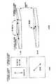
(株)ポラテクノ社製一軸延伸フィルムλ/4板(ポリビニルアルコール製,リターデーション:140nm) をλ/4板として,また,サンリッツ(株)社製直線偏光板HLC2−5618を用いて円偏光板を作製した。この時、直線偏光板の上に図1に示すように2枚のλ/4板を境界が接するように貼合した。軸配置は、2枚のλ/4板の延伸軸方位を互いに直交させ、偏光板の透過軸はλ/4板の延伸軸とそれぞれ45°をなすように配置し、粘着剤を介して積層した。このような配置により、図1上面図の左側が左円偏光板(左円偏光を透過)、右側が右円偏光板(右円偏光を透過)となる。
〈参考例2〉
〈円偏光板の作製▲2▼〉
富士写真フィルム(株)社製一軸延伸フィルムλ/4板(ポリカーボネイト製,リターデーション:153nm) をλ/4板として、また住友化学(株)製直線偏光板ST−1822APを用いて円偏光板を作製した。この時、λ/4板の上に図2に示すように2枚の直線偏光板を境界が接するように貼合した。軸配置は、2枚の偏光板の透過軸を互いに直交させ、λ/4板の延伸軸は偏光板の透過軸とれぞれ45°をなすように配置し、紫外線硬化型接着剤を介して積層した。このような配置により、図1上面図の左側が右円偏光板(右円偏光を透過)、右側が左円偏光板(左円偏光を透過)となる。
〈参考例3〉
〈コレステリック液晶フィルムの作製▲1▼〉
ガラス転移温度が80℃のR体光学活性化合物を含有する液晶性ポリエステル組成物をラビングポリイミド層を有するトリアセテートフィルム上にスピンコート法で成膜し、135℃で10分間熱処理したところ、緑色の鏡面反射を呈する面内に配向欠陥のないモノドメインなフィルムが得られた。同フィルムを日本分光(株)製紫外可視近赤外分光光度計V−570にて透過スペクトルを測定したところ、中心波長λsが約560nm、選択反射波長帯域幅Δλが約90nmの選択反射を示すコレステリック液晶層が形成されていることが確認された。また,透過スペクトルに周期的な規則正しいサイドバンドが観測されることから、コレステリック液晶層の螺旋ピッチPが膜厚方向に極めて均一であることが確認された。またR体光学活性化合物を用いたことから、螺旋軸の回転方向が左方向とあらかじめ分かっているコレステリック媒体が得られた。
〈参考例4〉
〈コレステリック液晶フィルムの作製▲2▼〉
ガラス転移温度が77℃のS体光学活性化合物を含有する液晶性ポリエステル組成物を、ラビングポリイミド層を有するトリアセテートフィルム上にスピンコート法で成膜し、140℃で10分間熱処理したところ、青色の鏡面反射を呈する面内に配向欠陥のないモノドメインなフィルムが得られた。同フィルムを日本分光(株)製紫外可視近赤外分光光度計V−570にて透過スペクトルを測定したところ、中心波長λsが約730nm、選択反射波長帯域幅Δλが約120nmの選択反射を示すコレステリック液晶層が形成されていることが確認された。また透過スペクトルに周期的な規則正しいサイドバンドが観測されることから、コレステリック液晶層の螺旋ピッチPが膜厚方向に極めて均一であることが確認された。またS体光学活性化合物を用いたことから、螺旋軸の回転方向が右方向とあらかじめ分かっているコレステリック媒体が得られた。
〈参考例5〉
〈コレステリック液晶フィルムの作製▲3▼非鏡面コレステリックフィルム〉
ガラス転移温度が80℃のS体光学活性化合物を含有する液晶性ポリエステル組成物を、ラビングポリイミド層を有するトリアセテートフィルム上にスピンコート法で成膜し、135℃で5分間熱処理したところ、黄緑色の非鏡面反射を呈するフィルムが得られた。偏光顕微鏡観察およびフィルム断面のTEM観察から、面内にオイリーストリークが形成されていることが確認できた。同フィルムを日本分光(株)製紫外可視近赤外分光光度計V−570にて透過スペクトル測定したところ,中心波長λsが約550nm,選択反射波長帯域幅Δλが約100nmの選択反射を示すコレステリック液晶層が形成されていることが確認された。またS体光学活性化合物を用いたことから,螺旋軸の回転方向が右方向とあらかじめ分かっているコレステリック媒体が得られた。
実施例1
参考例3に記載のコレステリックフィルムを黒色画用紙の上に置き、通常の室内光で照明した。この状態で、コレステリックフィルムを観察したところ、緑色の金属光沢のある反射光を観察できた。この反射光を参考例1に記載の円偏光板を通して観察したところ、右円偏光板(右円偏光を透過)を形成している領域では黒色が、左円偏光板(左円偏光を透過)を形成している領域では緑色が観察された。これより、左円偏光板(左円偏光を透過)を透過する光量の方が右円偏光板(右円偏光を透過)を透過する光量より多いので、反射光は左円偏光であることが簡単に識別できた。反射光が左円偏光であることから、参考例3のコレステリックフィルムの螺旋構造の回転方向は左であることが容易に判定できた。これは、参考例3のコレステリックフィルムに用いた光学活性化合物がR体であることとも合致する結果であった。
実施例2
参考例4に記載のコレステリックフィルムを黒色画用紙の上に置き、通常の室内光で照明した。この状態で、コレステリックフィルムを観察したところ、青色の金属光沢のある反射光を観察できた。この反射光を参考例2に記載の円偏光板を通して観察したところ、左円偏光板(左円偏光を透過)を形成している領域では黒色が、右円偏光板(右円偏光を透過)を形成している領域では青色が観察された。これより、右円偏光板(右円偏光を透過)を透過する光量の方が左円偏光板(左円偏光を透過)を透過する光量より多いので、反射光は右円偏光であることが簡単に識別できた。反射光が右円偏光であることから、参考例4のコレステリックフィルムの螺旋構造の回転方向は右であることが容易に判定できた。これは、参考例4のコレステリックフィルムに用いた光学活性化合物がS体であることとも合致する結果であった。
実施例3
参考例5に記載のコレステリックフィルムを黒色画用紙の上に置き、通常の室内光で照明した。この状態で、コレステリックフィルムを観察したところ、黄緑色のパステルカラーを呈する反射光を観察できた。この反射光を参考例1に記載の円偏光板を通して観察したところ、左円偏光板(左円偏光を透過)を形成している領域では黒色が、右円偏光板(右円偏光を透過)を形成している領域では黄緑色が観察された。これより、右円偏光板(右円偏光を透過)を透過する光量の方が左円偏光板(左円偏光を透過)を透過する光量より多いので、反射光は右円偏光であることが簡単に識別できた。反射光が右円偏光であることから、参考例5のコレステリックフィルムの螺旋構造の回転方向は右であることが容易に判定できた。これは、参考例5のコレステリックフィルムに用いた光学活性化合物がS体であることとも合致する結果であった。
比較例1
参考例3に記載のコレステリックフィルムを黒色画用紙の上に置き、通常の室内光で照明した。この状態で、コレステリックフィルムを観察したところ、緑色の金属光沢のある反射光を観察できた。この反射光を参考例1に記載の円偏光板を通して観察し、各偏光板の透過光量をトプコン(株)社製色彩輝度計BM−7を用いて1mの距離で測定角2°で輝度を測定したところ、右偏光板側で12cd/平方メートル、左偏光板側で243cd/平方メートルとなった。これより、左円偏光板(左円偏光を透過)を透過する光量の方が右円偏光板(右円偏光を透過)を透過する光量より多いので、反射光は左円偏光であることが識別できた。反射光が左円偏光であることから、参考例3のコレステリックフィルムの螺旋構造の回転方向は左であることが判別できた。これは参考例3のコレステリックフィルムに用いた光学活性化合物がR体であることとも合致する結果であった。
実施例1〜3および比較例1による判定結果の一覧を表1にまとめた。
【発明の効果】
本発明により、コレステリック媒体の螺旋構造の回転方向を、左右円偏光板の透過光量を比較することで簡便かつ迅速に判定することができる。本方法は、目視により判定できるとともに、輝度計などの測定装置を利用したシステムにも適用できる。
【図面の簡単な説明】
【図1】 参考例1に記述した円偏光板の構成例
【図2】 参考例2に記述した円偏光板の構成例
【表1】
BACKGROUND OF THE INVENTION
The present invention relates to a method for easily discriminating the rotational direction of a helical axis in a cholesteric medium such as a cholesteric liquid crystal or a cholesteric liquid crystal film obtained by filming the liquid crystal.
[0002]
[Prior art]
A cholesteric medium such as a cholesteric liquid crystal or a cholesteric film obtained by filming the liquid crystal has been focused on its unique optical characteristics, and has been considered to be applied as an optical element for a long time. The peculiarity of the optical characteristics is attributed to the fact that the orientation of the liquid crystal molecules has a helical structure. Further, since the specificity of the helical structure varies depending on the direction of rotation, it is important to examine the direction of rotation of the helical structure when using a cholesteric medium.
[0003]
As a method of examining the rotational direction of the spiral structure inside the cholesteric medium, right circularly polarized light and left circularly polarized light are respectively incident, and the amount of transmitted or reflected light for each polarized light is compared to determine the right and left of the rotational direction of the spiral structure. Methods are known.
[0004]
There is also a known method of determining the right and left of the rotational direction of the helical structure from the phase difference on the reference surface of circularly polarized light or elliptically polarized light by analyzing the polarization of light that is incident on natural light and transmitted or reflected by the cholesteric medium.
[0005]
These methods give high-precision measurement results, but on the other hand, the measurement method is complicated, it takes time, the measuring device is expensive, especially the trained measurer is required. It was not an excellent method.
[0006]
Therefore, it has been desired to develop a method that can easily and quickly discriminate the rotational direction of the helical structure of the cholesteric medium without depending on the measurer and without requiring a specially prepared optical measuring device.
[0007]
[Problems to be solved by the invention]
As a result of intensive studies on the optical characteristics of the cholesteric medium, the present inventors have found a method by which anyone can easily determine the rotational direction of the helical structure of the cholesteric medium without requiring a special optical device.
[0008]
[Means for Solving the Problems]
That is, the first aspect of the present invention uses one circularly polarizing plate in which at least one region that transmits left circularly polarized light and at least one region that transmits right circularly polarized light is mixed, and is transmitted or reflected from the left and right circularly polarized regions. The present invention relates to a method for discriminating the rotational direction of a spiral axis in a cholesteric medium based on a difference in the amount of light to be detected.
[0009]
A second aspect of the present invention is the cholesteric medium according to the first aspect of the present invention, which is a circularly polarizing plate in which two retardation films whose stretching axes are orthogonal to each other are stacked on one linear polarizer. It relates to a method for determining the direction of rotation of the spiral axis.
[0010]
Furthermore, a third aspect of the present invention is the cholesteric medium according to the first aspect of the present invention, which is a circularly polarizing plate in which two linear polarizers whose transmission axes are orthogonal to each other are stacked on a single retardation film. It relates to a method for determining the direction of rotation of the spiral axis.
[0011]
[Action]
In an optical medium having a regular twist that draws a spiral in the film thickness direction, such as cholesteric liquid crystal and chiral smectic C liquid crystal (SmC *), pitch P (film thickness necessary for liquid crystal molecules to rotate 360 °) And the incident light wavelength λ are approximately equal to each other, it is known to exhibit unique optical properties such as optical rotation and selective reflection (for example, liquid crystal and display application basics, Corona, ISBN 4-339-00620- 3). Optical rotatory power is a phenomenon observed as rotation of the plane of polarization when incident light is linearly polarized light. The selective reflectivity is a property of transmitting a specific circularly polarized light component in a specific wavelength band of incident light and reflecting a circularly polarized light component having the opposite rotation direction. A more peculiar point is that circularly polarized light that rotates in the opposite direction is reflected while the circularly polarized light component that rotates in the same direction as the twist direction of the optical medium is reflected in the incident light, and the rotation direction of the reflected light is also the same direction. The component is the point of transmission. Such selective reflectivity is manifested by being limited to a band called a selective reflection wavelength band. If the center wavelength is λs and the wavelength bandwidth is Δλ, these are the pitch P (= λ / n) of the optical medium. And the average refractive index n (Equation 1) are determined as shown in equations (1) and (2).
[0012]
[Expression 1]
Δλ = ΔnP (2)
In equation (2), Δn is the difference between the extraordinary ray refractive index ne and the ordinary ray refractive index no (Δn = ne−no) in the plane of the optical medium.
[0013]
Many applications have been proposed for a long time to use cholesteric liquid crystals as optical elements by utilizing their selective reflectivity. (For example, TJ Schiffer; Twisted nematic display with cholesterol reflector, J. Phys. D: Appl. Phys., Vol. 8, pp. 1441-8, 1975) Knowing the rotational direction of the helical axis of the cholesteric medium to be used is essential for design.
[0014]
DETAILED DESCRIPTION OF THE INVENTION
<Application of circularly polarizing plate>
In the present invention, a circularly polarizing plate is used to determine the rotational direction of the helical axis of the cholesteric medium. When natural light is incident on the cholesteric medium, the transmitted and reflected light is circularly polarized in the opposite rotational directions. If the transmitted and reflected light is observed using a circularly polarizing plate whose rotation direction of the circularly polarized light that is transmitted is known, the rotational direction of the spiral structure of the cholesteric medium can be determined from the difference in the amount of light transmitted through the circularly polarizing plate. I can do it. In this case, since it is difficult to observe the transmitted light and the reflected light simultaneously with one circular polarizing plate, when the degree of polarization is low, the amount of light transmitted from the circular polarizing plate is quantitatively measured by a measuring instrument. It is desirable to keep it.
[0015]
Also, if the rotation directions of the circularly polarized light that is transmitted are opposite to each other and two known circularly polarizing plates are used, if either the transmitted light or the reflected light is observed, the transmitted light amount of the two circularly polarizing plates From the difference, the rotation direction of the helical structure of the cholesteric medium can be determined. In this case, if the two circularly polarizing plates are formed on the same plane, the light transmitted through each of them can be observed at the same time, so that the rotational direction of the spiral axis of the cholesteric medium can be easily determined visually. . In addition, since it can be determined with high accuracy by quantitative comparison using a light quantity measuring device, it can also be applied to the case of a low degree of polarization. When comparing the amount of light by visual observation, it is possible to increase the accuracy by comparing and determining at the same time, rather than observing each of the two circularly polarizing plates independently to determine the difference in luminance. In particular, when the luminance difference is determined visually, it can be determined with the highest accuracy when the comparison objects are arranged so as to touch the boundary as widely known as the Mach effect. Therefore, as a circularly-polarizing plate used by this invention, it is desirable that the right and left circularly-polarizing plates are integrated so that a boundary may contact | connect.
【Example】
<Realization method of circularly polarizing plate>
A circularly polarizing plate can be easily realized by laminating a linearly polarizing plate and a λ / 4 plate (¼ wavelength plate). That is, since the phase difference between the linearly polarized light and the circularly polarized light is 90 degrees, by transmitting through the λ / 4 plate that is a uniaxial medium in which the phase difference between the fast axis and the slow axis is 90 degrees, Polarized light and circularly polarized light can be converted into each other. If the neutral axis (absorption axis or transmission axis) of the linear polarizing plate and the neutral axis (stretching axis) of the λ / 4 plate are 45 degrees, a polarizing plate having polarization selectivity with respect to circularly polarized light can be obtained. It can be easily realized (for example, Norihito Suzuki, Applied Optics 2, p.19, Asakura Shoten). As the linear polarizing plate and the λ / 4 plate, a sheet (film) is commercially available and can be easily obtained. If these are laminated and bonded in the above-described arrangement, a sheet-like circularly polarizing plate can be produced.
[0016]
As the linear polarizing plate, if it has linear polarization selectivity, such as a sheet polarizer containing iodine or a dye, a birefringent crystal such as a Nicol prism or a Grammuson prism, an anisotropic reflective multilayer film, etc. Although it can be used for this application, it is particularly preferable that a material processed on a sheet or film is excellent in handleability, and thus is preferable for carrying out the present invention.
[0017]
As the retardation plate, an optical element in which liquid crystal molecules are aligned to develop birefringence, an optical element in which birefringence is developed by a mechanical method such as extrusion and stretching, and a crystal having birefringence are used. It is possible to use an optical element or an optical element that utilizes the phase difference between the reflected p wave and s wave, such as Fresnel Rom, but it is particularly desirable to use a sheet or film processed for ease of handling. Because of its superiority, it is preferred for the practice of the present invention.
<Improved visibility when using a circularly polarizing plate>
The present invention determines the twist direction of the spiral structure of the cholesteric medium from the amount of light with respect to the light source by observing light transmitted or reflected through the cholesteric medium through a circularly polarizing plate. Further, as a method for facilitating the determination, it is possible to propose a method in which a region that transmits left circularly polarized light and a region that transmits right circularly polarized light are mixed in one circularly polarizing plate. That is, when either left or right circularly polarized light is incident on the circularly polarizing plate, there is a difference in the amount of transmitted light between the region that transmits the left circularly polarized light and the region that transmits the right circularly polarized light, resulting in a contrast. By observing this contrast, the twist direction can be determined more easily. In particular, when the degree of polarization of the cholesteric medium is low, the use of the circularly polarizing plate in which the region that transmits the left circularly polarized light and the region that transmits the right circularly polarized light is used in comparison with the case where a single unidirectional circularly polarizing plate is used. Thus, the twist direction of the spiral structure of the cholesteric medium can be determined more easily and with high accuracy.
<Reference Example 1>
<Production of circularly polarizing plate (1)>
Polatechno Co., Ltd. uniaxially stretched film λ / 4 plate (polyvinyl alcohol, retardation: 140 nm) as a λ / 4 plate, and Sanlitz Co., Ltd. linear polarizing plate HLC2-5618, circularly polarizing plate Was made. At this time, as shown in FIG. 1, two λ / 4 plates were bonded onto the linear polarizing plate so that the boundary was in contact. The axial arrangement is such that the orientation axes of the two λ / 4 plates are orthogonal to each other, and the transmission axes of the polarizing plates are arranged at 45 ° to the stretching axis of the λ / 4 plate, respectively, and are laminated via an adhesive. did. With this arrangement, the left side of the top view of FIG. 1 is a left circularly polarizing plate (transmits left circularly polarized light), and the right side is a right circularly polarizing plate (transmits right circularly polarized light).
<Reference Example 2>
<Production of circularly polarizing plate (2)>
A uniaxially stretched film λ / 4 plate manufactured by Fuji Photo Film Co., Ltd. (polycarbonate, retardation: 153 nm) is used as a λ / 4 plate, and a circularly polarizing plate using a linear polarizing plate ST-1822AP manufactured by Sumitomo Chemical Co., Ltd. Was made. At this time, as shown in FIG. 2, two linearly polarizing plates were bonded onto the λ / 4 plate so that the boundary was in contact. The axial arrangement is such that the transmission axes of the two polarizing plates are orthogonal to each other, and the stretching axis of the λ / 4 plate is arranged to form 45 ° with the transmission axis of the polarizing plate, respectively, via an ultraviolet curable adhesive Laminated. With such an arrangement, the left side of the top view of FIG. 1 is a right circularly polarizing plate (transmits right circularly polarized light), and the right side is a left circularly polarizing plate (transmits left circularly polarized light).
<Reference Example 3>
<Preparation of cholesteric liquid crystal film (1)>
When a liquid crystalline polyester composition containing an R-type optically active compound having a glass transition temperature of 80 ° C. is formed on a triacetate film having a rubbing polyimide layer by spin coating and heat-treated at 135 ° C. for 10 minutes, a green mirror surface is obtained. A monodomain film free from alignment defects was obtained in the plane exhibiting reflection. When the transmission spectrum of the film was measured with an ultraviolet-visible near-infrared spectrophotometer V-570 manufactured by JASCO Corporation, it showed selective reflection with a center wavelength λs of about 560 nm and a selective reflection wavelength bandwidth Δλ of about 90 nm. It was confirmed that a cholesteric liquid crystal layer was formed. Moreover, since periodic regular sidebands are observed in the transmission spectrum, it has been confirmed that the helical pitch P of the cholesteric liquid crystal layer is extremely uniform in the film thickness direction. Further, since the R-type optically active compound was used, a cholesteric medium in which the rotation direction of the helical axis was previously known as the left direction was obtained.
<Reference Example 4>
<Preparation of cholesteric liquid crystal film (2)>
A liquid crystalline polyester composition containing an S-form optically active compound having a glass transition temperature of 77 ° C. was formed by spin coating on a triacetate film having a rubbing polyimide layer, and heat-treated at 140 ° C. for 10 minutes. A monodomain film free from alignment defects was obtained in the plane exhibiting specular reflection. When the transmission spectrum of the film was measured with an ultraviolet-visible near-infrared spectrophotometer V-570 manufactured by JASCO Corporation, it showed selective reflection with a center wavelength λs of about 730 nm and a selective reflection wavelength bandwidth Δλ of about 120 nm. It was confirmed that a cholesteric liquid crystal layer was formed. Moreover, since periodic regular sidebands were observed in the transmission spectrum, it was confirmed that the helical pitch P of the cholesteric liquid crystal layer was extremely uniform in the film thickness direction. Moreover, since the S-form optically active compound was used, a cholesteric medium in which the rotational direction of the helical axis was previously known as the right direction was obtained.
<Reference Example 5>
<Preparation of cholesteric liquid crystal film (3) Non-specular cholesteric film>
A liquid crystalline polyester composition containing an S-form optically active compound having a glass transition temperature of 80 ° C. was formed on a triacetate film having a rubbing polyimide layer by a spin coating method and heat-treated at 135 ° C. for 5 minutes. A film exhibiting non-specular reflection was obtained. From observation with a polarizing microscope and TEM observation of the film cross section, it was confirmed that oily streaks were formed in the plane. When the transmission spectrum of the film was measured with an ultraviolet-visible near-infrared spectrophotometer V-570 manufactured by JASCO Corporation, the cholesteric showed selective reflection with a center wavelength λs of about 550 nm and a selective reflection wavelength bandwidth Δλ of about 100 nm. It was confirmed that a liquid crystal layer was formed. In addition, since the S-form optically active compound was used, a cholesteric medium in which the rotational direction of the helical axis was previously known as the right direction was obtained.
Example 1
The cholesteric film described in Reference Example 3 was placed on black drawing paper and illuminated with normal room light. In this state, when the cholesteric film was observed, reflected light having a green metallic luster could be observed. When this reflected light was observed through the circularly polarizing plate described in Reference Example 1, black was left in the region forming the right circularly polarizing plate (transmitting the right circularly polarized light), but the left circularly polarizing plate (transmitting the left circularly polarized light) Green was observed in the area forming As a result, the amount of light passing through the left circularly polarizing plate (transmitting the left circularly polarized light) is greater than the amount of light passing through the right circularly polarizing plate (transmitting the right circularly polarized light), so that the reflected light is left circularly polarized light. It was easy to identify. Since the reflected light was left circularly polarized light, it was easily determined that the rotational direction of the spiral structure of the cholesteric film of Reference Example 3 was left. This was a result consistent with the fact that the optically active compound used in the cholesteric film of Reference Example 3 was R-form.
Example 2
The cholesteric film described in Reference Example 4 was placed on black drawing paper and illuminated with normal room light. In this state, when the cholesteric film was observed, reflected light with a blue metallic luster could be observed. When this reflected light was observed through the circularly polarizing plate described in Reference Example 2, it was black in the region forming the left circularly polarizing plate (transmitting the left circularly polarized light), but the right circularly polarizing plate (transmitting the right circularly polarized light). Blue was observed in the region forming As a result, the amount of light passing through the right circularly polarizing plate (transmitting the right circularly polarized light) is larger than the amount of light passing through the left circularly polarizing plate (transmitting the left circularly polarized light), so that the reflected light is right circularly polarized light. It was easy to identify. Since the reflected light was right circularly polarized light, it was easily determined that the rotation direction of the spiral structure of the cholesteric film of Reference Example 4 was right. This was a result consistent with the fact that the optically active compound used in the cholesteric film of Reference Example 4 was S form.
Example 3
The cholesteric film described in Reference Example 5 was placed on black drawing paper and illuminated with normal room light. When the cholesteric film was observed in this state, reflected light having a yellow-green pastel color could be observed. When this reflected light is observed through the circularly polarizing plate described in Reference Example 1, black is right in the region where the left circularly polarizing plate (transmits the left circularly polarized light) is formed, and the right circularly polarizing plate (transmits the right circularly polarized light). A yellowish green color was observed in the area where the film was formed. As a result, the amount of light passing through the right circularly polarizing plate (transmitting the right circularly polarized light) is larger than the amount of light passing through the left circularly polarizing plate (transmitting the left circularly polarized light), so that the reflected light is right circularly polarized light. It was easy to identify. Since the reflected light was right circularly polarized light, it was easily determined that the rotation direction of the spiral structure of the cholesteric film of Reference Example 5 was right. This was a result consistent with the fact that the optically active compound used in the cholesteric film of Reference Example 5 was S form.
Comparative Example 1
The cholesteric film described in Reference Example 3 was placed on black drawing paper and illuminated with normal room light. In this state, when the cholesteric film was observed, reflected light having a green metallic luster could be observed. This reflected light is observed through the circularly polarizing plate described in Reference Example 1, and the amount of light transmitted through each polarizing plate is measured with a luminance meter BM-7 manufactured by Topcon Corporation at a measurement angle of 2 ° at a distance of 1 m. When measured, it was 12 cd / square meter on the right polarizing plate side and 243 cd / square meter on the left polarizing plate side. As a result, the amount of light passing through the left circularly polarizing plate (transmitting the left circularly polarized light) is larger than the amount of light passing through the right circularly polarizing plate (transmitting the right circularly polarized light), so that the reflected light is left circularly polarized light. I was able to identify. Since the reflected light was left circularly polarized light, it was determined that the rotational direction of the spiral structure of the cholesteric film of Reference Example 3 was left. This was a result consistent with the fact that the optically active compound used in the cholesteric film of Reference Example 3 was R-form.
A list of determination results according to Examples 1 to 3 and Comparative Example 1 is summarized in Table 1.
【The invention's effect】
According to the present invention, the rotational direction of the spiral structure of the cholesteric medium can be easily and quickly determined by comparing the amount of light transmitted through the left and right circularly polarizing plates. This method can be determined visually, and can also be applied to a system using a measuring device such as a luminance meter.
[Brief description of the drawings]
1 is a configuration example of a circularly polarizing plate described in Reference Example 1. FIG. 2 is a configuration example of a circularly polarizing plate described in Reference Example 2.
Claims (3)
Translated fromJapanesePriority Applications (1)
| Application Number | Priority Date | Filing Date | Title |
|---|---|---|---|
| JP37053497AJP3821940B2 (en) | 1997-12-19 | 1997-12-19 | Method for discriminating the direction of rotation of the helical axis in cholesteric media |
Applications Claiming Priority (1)
| Application Number | Priority Date | Filing Date | Title |
|---|---|---|---|
| JP37053497AJP3821940B2 (en) | 1997-12-19 | 1997-12-19 | Method for discriminating the direction of rotation of the helical axis in cholesteric media |
Publications (2)
| Publication Number | Publication Date |
|---|---|
| JPH11183371A JPH11183371A (en) | 1999-07-09 |
| JP3821940B2true JP3821940B2 (en) | 2006-09-13 |
Family
ID=18497162
Family Applications (1)
| Application Number | Title | Priority Date | Filing Date |
|---|---|---|---|
| JP37053497AExpired - LifetimeJP3821940B2 (en) | 1997-12-19 | 1997-12-19 | Method for discriminating the direction of rotation of the helical axis in cholesteric media |
Country Status (1)
| Country | Link |
|---|---|
| JP (1) | JP3821940B2 (en) |
Cited By (1)
| Publication number | Priority date | Publication date | Assignee | Title |
|---|---|---|---|---|
| WO2019059067A1 (en) | 2017-09-22 | 2019-03-28 | 日本ゼオン株式会社 | Viewer for determination of authenticity |
Families Citing this family (4)
| Publication number | Priority date | Publication date | Assignee | Title |
|---|---|---|---|---|
| FR2826857B1 (en) | 2001-07-09 | 2004-03-12 | Oreal | INSTRUMENT FOR OBSERVING SKIN OR HAIR |
| FR2878424B1 (en) | 2004-11-26 | 2008-02-01 | Oreal | METHOD FOR OBSERVING A BIOLOGICAL TISSUE, IN PARTICULAR HUMAN SKIN |
| JP2014010093A (en)* | 2012-07-02 | 2014-01-20 | Seiko Epson Corp | Spectral image pickup device |
| CN107300726A (en)* | 2017-07-17 | 2017-10-27 | 南方科技大学 | All-solid-state reflecting film and preparation method thereof |
- 1997
- 1997-12-19JPJP37053497Apatent/JP3821940B2/ennot_activeExpired - Lifetime
Cited By (2)
| Publication number | Priority date | Publication date | Assignee | Title |
|---|---|---|---|---|
| WO2019059067A1 (en) | 2017-09-22 | 2019-03-28 | 日本ゼオン株式会社 | Viewer for determination of authenticity |
| US11442211B2 (en) | 2017-09-22 | 2022-09-13 | Zeon Corporation | Viewer for determination of authenticity |
Also Published As
| Publication number | Publication date |
|---|---|
| JPH11183371A (en) | 1999-07-09 |
Similar Documents
| Publication | Publication Date | Title |
|---|---|---|
| US6795246B2 (en) | Optical film, polarizer and display device | |
| TWI578031B (en) | A liquid crystal display device and a publishing crystal and a polarizing light source device | |
| EP1045261B1 (en) | Phase difference film and optical device using it | |
| JP5000729B2 (en) | Manufacturing method of liquid crystal display device and liquid crystal display device | |
| JP3805623B2 (en) | Liquid crystalline film | |
| JP6858206B2 (en) | Liquid crystal display device | |
| TW528893B (en) | Optical film, polarizer and display device | |
| JP2005504341A (en) | Polarization rotator, articles containing polarization rotators, and methods for making and using them | |
| TW201017236A (en) | Liquid crystal display device | |
| US8115895B2 (en) | Optical compensation film and liquid crystal display device using the same | |
| JP2005504333A (en) | Polarization rotator and method for producing article containing polarization rotator | |
| JPH09274108A (en) | Polarizing element and liquid crystal display device | |
| KR20070056055A (en) | Compensation Film for Eliminating Light Leaks through LCC Cross Polarizer | |
| US20070146597A1 (en) | Retardation optical element and method of producing the same, and polarization element and liquid crystal display, each including retardation optical element | |
| JP4276392B2 (en) | Circularly polarizing plate and liquid crystal display using the same | |
| JP7264055B2 (en) | Authenticity judgment viewer | |
| JP2002048919A (en) | Optical retardation film | |
| JPH0242406A (en) | Retardation plate, composite polarizing plate using the same, and liquid crystal display device | |
| JP3821940B2 (en) | Method for discriminating the direction of rotation of the helical axis in cholesteric media | |
| JP3836283B2 (en) | Polycarbonate laminated retardation film | |
| Lin et al. | Measuring electric-field-induced birefringence in polymer stabilized blue-phase liquid crystals based on phase shift measurements | |
| JP4488549B2 (en) | Reflective liquid crystal display element | |
| EP0969296A2 (en) | Color Reflection type polarizer | |
| JP2007121996A (en) | Optical compensation sheet, and polarizing plate and liquid crystal display device using the same | |
| Sergan et al. | Negative uniaxial films from lyotropic liquid crystalline material for liquid crystal display applications |
Legal Events
| Date | Code | Title | Description |
|---|---|---|---|
| A621 | Written request for application examination | Free format text:JAPANESE INTERMEDIATE CODE: A621 Effective date:20041206 | |
| A977 | Report on retrieval | Free format text:JAPANESE INTERMEDIATE CODE: A971007 Effective date:20060608 | |
| TRDD | Decision of grant or rejection written | ||
| A01 | Written decision to grant a patent or to grant a registration (utility model) | Free format text:JAPANESE INTERMEDIATE CODE: A01 Effective date:20060620 | |
| A61 | First payment of annual fees (during grant procedure) | Free format text:JAPANESE INTERMEDIATE CODE: A61 Effective date:20060621 | |
| R150 | Certificate of patent or registration of utility model | Free format text:JAPANESE INTERMEDIATE CODE: R150 | |
| FPAY | Renewal fee payment (event date is renewal date of database) | Free format text:PAYMENT UNTIL: 20100630 Year of fee payment:4 | |
| FPAY | Renewal fee payment (event date is renewal date of database) | Free format text:PAYMENT UNTIL: 20100630 Year of fee payment:4 | |
| FPAY | Renewal fee payment (event date is renewal date of database) | Free format text:PAYMENT UNTIL: 20110630 Year of fee payment:5 | |
| FPAY | Renewal fee payment (event date is renewal date of database) | Free format text:PAYMENT UNTIL: 20110630 Year of fee payment:5 | |
| S531 | Written request for registration of change of domicile | Free format text:JAPANESE INTERMEDIATE CODE: R313531 | |
| S533 | Written request for registration of change of name | Free format text:JAPANESE INTERMEDIATE CODE: R313533 | |
| FPAY | Renewal fee payment (event date is renewal date of database) | Free format text:PAYMENT UNTIL: 20110630 Year of fee payment:5 | |
| R350 | Written notification of registration of transfer | Free format text:JAPANESE INTERMEDIATE CODE: R350 | |
| FPAY | Renewal fee payment (event date is renewal date of database) | Free format text:PAYMENT UNTIL: 20110630 Year of fee payment:5 | |
| FPAY | Renewal fee payment (event date is renewal date of database) | Free format text:PAYMENT UNTIL: 20120630 Year of fee payment:6 | |
| FPAY | Renewal fee payment (event date is renewal date of database) | Free format text:PAYMENT UNTIL: 20120630 Year of fee payment:6 | |
| FPAY | Renewal fee payment (event date is renewal date of database) | Free format text:PAYMENT UNTIL: 20130630 Year of fee payment:7 | |
| R250 | Receipt of annual fees | Free format text:JAPANESE INTERMEDIATE CODE: R250 | |
| R250 | Receipt of annual fees | Free format text:JAPANESE INTERMEDIATE CODE: R250 | |
| R250 | Receipt of annual fees | Free format text:JAPANESE INTERMEDIATE CODE: R250 | |
| R250 | Receipt of annual fees | Free format text:JAPANESE INTERMEDIATE CODE: R250 | |
| S531 | Written request for registration of change of domicile | Free format text:JAPANESE INTERMEDIATE CODE: R313531 | |
| S533 | Written request for registration of change of name | Free format text:JAPANESE INTERMEDIATE CODE: R313533 | |
| R350 | Written notification of registration of transfer | Free format text:JAPANESE INTERMEDIATE CODE: R350 | |
| R250 | Receipt of annual fees | Free format text:JAPANESE INTERMEDIATE CODE: R250 | |
| S533 | Written request for registration of change of name | Free format text:JAPANESE INTERMEDIATE CODE: R313533 | |
| R350 | Written notification of registration of transfer | Free format text:JAPANESE INTERMEDIATE CODE: R350 | |
| EXPY | Cancellation because of completion of term |