JP3821622B2 - Projection display - Google Patents
Projection displayDownload PDFInfo
- Publication number
- JP3821622B2 JP3821622B2JP34931799AJP34931799AJP3821622B2JP 3821622 B2JP3821622 B2JP 3821622B2JP 34931799 AJP34931799 AJP 34931799AJP 34931799 AJP34931799 AJP 34931799AJP 3821622 B2JP3821622 B2JP 3821622B2
- Authority
- JP
- Japan
- Prior art keywords
- light
- light sources
- reflectors
- display device
- optical path
- Prior art date
- Legal status (The legal status is an assumption and is not a legal conclusion. Google has not performed a legal analysis and makes no representation as to the accuracy of the status listed.)
- Expired - Fee Related
Links
Images


Classifications
- H—ELECTRICITY
- H04—ELECTRIC COMMUNICATION TECHNIQUE
- H04N—PICTORIAL COMMUNICATION, e.g. TELEVISION
- H04N9/00—Details of colour television systems
- H04N9/12—Picture reproducers
- H04N9/31—Projection devices for colour picture display, e.g. using electronic spatial light modulators [ESLM]
- H04N9/3102—Projection devices for colour picture display, e.g. using electronic spatial light modulators [ESLM] using two-dimensional electronic spatial light modulators
- H04N9/3105—Projection devices for colour picture display, e.g. using electronic spatial light modulators [ESLM] using two-dimensional electronic spatial light modulators for displaying all colours simultaneously, e.g. by using two or more electronic spatial light modulators
- H—ELECTRICITY
- H04—ELECTRIC COMMUNICATION TECHNIQUE
- H04N—PICTORIAL COMMUNICATION, e.g. TELEVISION
- H04N9/00—Details of colour television systems
- H04N9/12—Picture reproducers
- H04N9/31—Projection devices for colour picture display, e.g. using electronic spatial light modulators [ESLM]
- H04N9/3141—Constructional details thereof
- H04N9/315—Modulator illumination systems
- H04N9/3164—Modulator illumination systems using multiple light sources
Landscapes
- Engineering & Computer Science (AREA)
- Multimedia (AREA)
- Signal Processing (AREA)
- Projection Apparatus (AREA)
- Liquid Crystal (AREA)
- Optical Elements Other Than Lenses (AREA)
- Devices For Indicating Variable Information By Combining Individual Elements (AREA)
- Video Image Reproduction Devices For Color Tv Systems (AREA)
Description
Translated fromJapanese【0001】
【発明の属する技術分野】
本発明は、投射型液晶プロジェクタに関し、特に、液晶プロジェクタの液晶表示装置の照明光の角度制御に関するものである。
【0002】
【従来の技術】
従来、液晶プロジェクタ等の液晶表示装置は、光源ランプからの出謝光を液晶ライトバルブに照射して、該液晶ライトバルブにおいて、照射された光に表示画像に対応した変調を施した後に、投写光学系を介して投写面上に投写画像を形成するようにされている。
しかしながら、前記液晶ライトバルブにおける照射光の変調処理は、画像情報に対応した特定の偏光成分のみを使用するため、光源ランプからの出謝光をそのまま液晶ライトバルブに照射しても、偏光方向が異なる光成分は利用されない。そのため、投写画像を明るくするためには、ワット数の高い光源ランプを使用して光源の輝度を高める必要があった。
【0003】
そこで、特開平11−96803号公報や、1999年4月テクノタイムズ社発刊の「月刊ディスプレイ」VOL.5 No.4等に開示されているように、複数の照明光源を用いた投射型プロジェクタの光源装置が提案されている。
ここで、前記光源装置を図を参照して説明する。図6は従来の投射型表示装置の光学部品の構成を示す概略図を示すものである。
前記光源装置の構成は、例えば、図5に示すように、光源1、2と、前記光源1、2からの光を反射するためのリフレクタ3、4と、前記リフレクタ3、4で反射された各々の光源1、2からの光を同一方向に反射するための反射鏡29を備えたものであって、前記リフレクタ3、4は、前記反射鏡29をはさんで対向して配置され、前記反射鏡29は、前記リフレクタ3、4に対して各々45°傾斜して、いわゆる「ハの字状」に配置されている。
【0004】
前記リフレクタ3、4で反射された各々の光源1、2からの反射光は、前記反射鏡29によって同一方向に反射され、一対のフライアイレンズ6、7および偏光素子8を通過して、コンデンサーレンズ9〜14および色分離・反射ミラー15〜20によって、映像信号変換用ライトバルブ21〜23に集光される。そして、3色に色分解された映像信号は色合成プリズム24によって、1つの光路に合成され、投写レンズ25によって、拡大投影されるものである。
【0005】
【発明が解決しようとする課題】
しかしながら、このような構成によると、色分離・反射ミラー15〜20、色合成プリズム24および投写レンズ25への入射光角度特性が光源1からの光と光源2からの光とでは異なるため、光源1と2の照度差による色ムラや1光源での投影時の色ムラが発生するという問題がある。
【0006】
ここで、入射角度分布の比較を図面を参照して説明する。
図7は従来の反射ミラーによるミラー入射角度分布を示すグラフ、図8の(a)は従来の反射ミラーによる光路の進行を示す説明図、(b)は従来の反射ミラーによる光の強度分布を示す説明図である。
従来の反射ミラーによるミラー入射角度分布は、図7に示すように、色分離・反射ミラー15における光源1、2からの光の入射角度分布の入射角度に応じた光強度を表したものである。図6によると、光源1と光源2の入射角度分布の差により、色分離・反射ミラー15の色分離分光特性が異なることが分かる。これにより色ムラが発生するわけである。
【0007】
次に、投射レンズの瞳における光源1からの光の強度分布は、図8の(a)、(b)に示すように、投射レンズの物面の像高がセンター(LCD中央部)の場合の光の強度分布を表したものである。これによると、像高が変化すると取り込む光量が変化するため、像高が大きくなるにしたがって瞳が潰れる。従って、Rch、Gchの照明光の角度分布と1度反転するBchの照明光の角度分布に設計上差が生じて、投射レンズでの取り込む光量や色配分に差が生じると、結果的に拡大投影像の色ムラが発生するわけである。
【0008】
本発明は、前記従来の問題点に鑑みてなされたものであって、光源に応じて、色分離ミラーや色合成プリズム部、投射レンズ部のそれぞれの角度分布が偏ることのなく、色ムラを改善した投射型表示装置を提供することを目的とする。
【0009】
【課題を解決するための手段】
本発明は、前記目的を達成するため、複数の光源より発せられた光を、フライアイレンズ等のインテグレータ部を介してコンデンサーレンズ等の所定の光路を経由し、液晶パネル等のライトバルブに集光して、該ライトバルブで映像情報に変換するようにした投射型表示装置であって、複数の光源を備え、前記光源の光を集光するための複数のリフレクタを備えると共に、前記リフレクタで集光された光を階段状に配置された複数のプリズムで同一方向に分割反射するための分割反射手段を備えた投射型表示装置において、前記分割反射手段は、光路方向に向けて直角部分を配置し、該直角部を挟んだ2面に反射膜が施された複数の直角三角柱プリズムから成り、前記直角三角柱プリズムを離散的に配置し、隣接するプリズム同士を光路方向でプリズムの高さとほぼ同寸法ずつずらして配置し、前記分割反射手段による反射光幅を、フライアイレンズの単セル幅の整数倍とすることを特徴とするものである。
【0010】
また、本発明は、複数の光源より発せられた光を、フライアイレンズ等のインテグレータ部を介してコンデンサーレンズ等の所定の光路を経由し、液晶パネル等のライトバルブに集光して、該ライトバルブで映像情報に変換するようにした投射型表示装置であって、複数の光源を備え、前記光源の光を集光するための複数のリフレクタを備えると共に、前記リフレクタで集光された光を階段状に配置された複数のプリズムで同一方向に分割反射するための分割反射手段を備えた投射型表示装置において、前記光源は、第1の光源と第2の光源を備え、前記リフレクタは、第1のリフレクタと第2のリフレクタを備え、前記分割反射手段は、前記プリズムの傾斜面を前記第1のリフレクタの開口部に対して平行に対向させ、もう一方の傾斜面を光路方向に向けて配置する全反射プリズムと、傾斜面を第2のリフレクタの開口部に対して平行に対向させ、もう一方の傾斜面を光路方向に向けて配置する全反射プリズムを連結し、連続的にプリズムの高さとほぼ同寸法ずつずらして配置してなり、前記分割反射手段による反射光幅を、フライアイレンズの単セル幅の整数倍とするものである。
また、本発明は、複数の光源より発せられた光を、フライアイレンズ等のインテグレータ部を介してコンデンサーレンズ等の所定の光路を経由し、液晶パネル等のライトバルブに集光して、該ライトバルブで映像情報に変換するようにした投射型表示装置において、複数の光源を備え、前記光源の光を集光するための複数のリフレクタを備えると共に、前記リフレクタで集光された光を複数の短冊状に、かつ、ほぼ同一方向に分割反射するための分割反射手段を備え、前記分割反射手段は、ガラス板に反射層と透明層を交互に配置し、前記ガラス板を前記リフレクタの開口部に対して45°傾向させてハの字状であって該ガラス基板を交互に対向させて、かつ、平行に2列並設配置して、該分割反射手段による反射光幅を、フライアイレンズの単セル幅の整数倍とするものである。
【0011】
本発明によれば、複数の光源と前記光源の光を集光するための複数のリフレクタを備えることにより、照射光の輝度を高めることができる。さらに、リフレクタで集光された光を複数の短冊状に、かつ、ほぼ同一方向に分割反射するための分割反射手段を備えることにより、色分離・反射ミラーの入射角度分布や投射レンズへの入射角度分布を偏りのない分布にすることができるので、投影像の色ムラの改善を図ることができる。
【0012】
また、前記分割反射手段による反射光幅をフライアイレンズの単セル幅の整数倍とすることにより、色分離・反射ミラーの入射角度分布や投射レンズへの入射角度分布を偏りのない分布にすることができる。
また、前記分割反射手段を、プリズムの直角部を挟んだ2面に反射膜を施し、前記プリズムをアレイ状に配置することにより、複数の小さな反射ミラーを用いて、簡単な構成で省スペース化が実現できる。
また、前記分割反射手段として、反射ミラー層を有するガラス板を用いることにより、低コストで前記と同様な効果を奏することができる。
【0013】
【発明の実施の形態】
以下、図面を参照して本発明の実施形態を詳細に説明する。
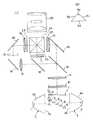
図1は本発明の実施形態に係る投射型表示装置の光学部品の構成を示す概略図、(a)は本実施形態のプリズムの詳細を示す正面図、図2の(a)は本実施形態の三角柱プリズムによる光路の進行を示す説明図、(b)は本実施形態の三角柱プリズムよる光の強度分布を示す説明図である。
【0014】
本実施形態は、図1の(a)に示すように、2つの光源1、2より発せられた光を、フライアイレンズ6、7等のインテグレータ部を介してコンデンサーレンズ9〜14等の所定の光路を経由し、液晶パネル等の液晶ライトバルブ21〜23に集光して、該液晶ライトバルブ21〜23で映像情報に変換するようにした投射型表示装置において、2つの光源1、2と、前記光源1、2の光を集光するための2つのパラボラリフレクタ3、4を備えると共に、前記パラボラリフレクタ3、4で集光された光を複数の短冊状に、かつ、ほぼ同一方向に分割反射するためのプリズム5を備えるものである。
【0015】
前記パラボラリフレクタ3、4は、前記光源1、2を各々包囲すると共に前記光源1、2からの光を反射するための反射板3a、4aと、反射された光が出謝される開口3b、4bを有してなり、該パラボラリフレクタ3、4の間に複数の前記プリズム5を介在して各々の開口部3b、4bが対向して配置されている。
【0016】
前記プリズム5は、図1の(b)に示すように、直角部を5aとして、該直角部5aを挟む面(以下、傾斜面と称する。)を5b、5cとし、該直角部5aと対向する面(以下、底面と称する。)5dとする。前記傾斜面5b、5cの表面は、可視光増反射アルミ蒸着、またはコールドミラー蒸着が施されており、傾斜面の幅dをフライアイレンズの単セル幅fdの整数倍とされ、かつ、前記フライアイレンズのセル境界fyと該プルズムによる光の合成境界pyを一致させている。
また、前記プリズム5は、底面5dを前記パラボラリフレクタ3、4とほぼ直角となる位置に配置されている。すなわち、傾斜面5b、5cは各々45°の角度をもって前記パラボラリフレクタ3、4の開口部3b、4bと対向する位置に配置され、直角部5aは、所定の光路に向けて配置される。
また、前記プリズム5は、隣接するプリズム5同士が、光源1、2に対してほぼ平行でかつ底面5dの幅とほぼ同寸法ずつずれ配置されると共に、光路方向でプリズム5の高さとほぼ同寸法ずつずれて階段状に配置されいる。
【0017】
次に、本実施形態の作用について説明する。
まず、前記光源1、2から発せられた光線は、図1、2の(a)に示すように、前記パラボラリフレクタ3、4によってお互いに対向する方向に集光される。集光された光線は、段階状に配置されたプリズム5によってほぼ直角方向に反射される。そして、一対のフライアイレンズ6、7および偏光素子8を通過して、コンデンサーレンズ9〜14および色分離・反射ミラー15〜20によって、映像信号変換用ライトバルブ21〜23に集光される。前記映像信号変換用ライトバルブ21〜23において3色に色分解された映像信号は色合成プリズムニ24よって、1光路に合成され、投写レンズ25によって、拡大投影される。
【0018】
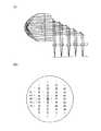
本実施形態によるプリズムによると、図3に示すように、光源1、2における入射角度による光強度は、図7に示す従来の反射ミラーによるミラー入射角度分布と比較して、光源1、2共に入射角度45°近辺を中心にほぼ対称に分布することができるため、光源の違いによる色ムラの発生を低減することができる。
また、図2の(b)に示すように、光源からの光の投影レンズ瞳像の瞳上での偏りを低減することができるため、投影レンズによる取り込み色配分の差を少なくすることにより、色ムラの発生を低減できる。
【0019】
また、本実施形態のようなプリズム5の配置によると、光源1、2からの光は櫛形に分離されてお互いの隙間を補間するように合成することができる。すなわち、光源1、2の光を交互に配列することにより、光源の違いによる入射角度に応じた光強度の差を相殺することができる。また、前記プリズムのフライアイ6側からの見かけ上の幅dをフライアイの単セル幅fdの整数倍とすると共に、フライアイのセル境界fyと前記プリズムによる光の合成境界pyを一致させることにより、光源による投影像の照度差を低減することができる。
【0020】
なお、本実施形態においては、複数のプリズム5をほぼ等間隔に、かつ、階段上に配置しているが、本発明はこれに限定するものではなく、例えば、変形例1として、図4の(a)に示すように、可視光増反射アルミ蒸着、または、コールドミラー蒸着された反射層と透明層を交互に配置するガラス基板26、27をパラボラリフレクタの開口部に対して45°傾向させて「ハの字」状であって該ガラス基板26、27を交互に対向させて、かつ、ほぼ平行に2列並設させるものであってもよい。
図4の(b)および(c)は、変形例1の反射ミラー26、27の構成を示す詳細図である。
【0021】
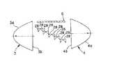
また、変形例2として、図5に示すように、プリズムの傾斜面28bをパラボラリフレクタ3の開口部3aに対してほぼ平行に対向させ、もう一方の傾斜面を光路方向に向けて配置する全反射プリズム28と、傾斜面28cをパラボラリフレクタ4の開口部4aに対してほぼ平行に対向させ、もう一方の傾斜面28bを光路方向に向けて配置する全反射プリズム28を連結し、前記実施形態のように、連続的に階段状に配置するようにしたものであってもよい。
【0022】
前記変形例1、2の何れの場合においても、光源1、2からの2つの光を混ぜ合わせる効果により、光源1、2の照度差や片側1灯出の点灯時に、光の色分離ミラー、色合成プリズムおよび投射レンズへの入射光角度特性の偏りを、図3に示すものと同様に光量分布を改善することができる。
【0023】
さらに、その他の例として、複数の光源を使用した投射型表示装置において、その光源を任意または規則的に点灯および消灯自在とする光源制御手段を備えるものであってもよい。この場合には、複数の光源のON/OFFの組み合わせによる調光システムが可能になり、さらに光量分布の改善を図ることができる。
【0024】
【発明の効果】
以上説明した通り本発明によれば、投射型表示装置において、複数の光源と複数のリフレクタを備え、プリズムなどを用いた複数の分割反射手段を備えて、複数の光源の光を混ぜ合わせることにより、色分離・反射ミラーの入射角度分布や投射レンズへの入射角度分布を偏りのない分布にすることができ、従って、投影像の色ムラの低減を図ることができるという効果がある。
また、プリズムを有効に使用することにより、さらに簡単な構成で、投影像の色ムラの低減を図ることができるという優れた効果を有する。
【図面の簡単な説明】
【図1】(a)は本発明の実施形態に係る投射型表示装置の光学部品の構成を示す概略図、(b)は前記光学部品のひとつの三角柱プリズムの詳細図である。
【図2】(a)は本実施形態の三角柱プリズムによる光路の進行を示す説明図、(b)は本実施形態の三角柱プリズムによる光の強度分布を示す説明図である。
【図3】本実施形態のミラー入射角度分布を示すグラフである。
【図4】(a)は本実施形態の変形例1の投射型表示装置の光学部品の構成を示す概略図、(b)は変形例1の反射ミラー26の構成を示す詳細図、(c)は変形例1の反射ミラー27の構成を示す詳細図である。
【図5】本実施形態の変形例2の投射型表示装置の光学部品の構成を示す概略図である。
【図6】従来の投射型表示装置の光学部品の構成を示す概略図である。
【図7】従来のミラー入射角度分布を示すグラフである。
【図8】(a)は従来の投射型表示装置の光路の進行を示す説明図、(b)は従来の反射ミラーによる光の強度分布を示す説明図である。
【符号の説明】
1、2 光源
3、4 パラボラリフレクタ
5 三角柱プリズム
5a 直角部
5b、5c 傾斜面
5d 底面
6、7 フライアイズレンズ
8 偏光素子
9〜14 コンデンサーレンズ
10〜20 色分離・反射ミラー
21〜23 映像信号用ライトバルブ
24 色合成プリズム
25 投写レンズ
26、27 ガラス基板
26a、27a 反射層
26b、27b 透明層
28 全反射プリズム
29 反射鏡[0001]
BACKGROUND OF THE INVENTION
The present invention relates to a projection type liquid crystal projector, and more particularly to angle control of illumination light of a liquid crystal display device of a liquid crystal projector.
[0002]
[Prior art]
Conventionally, a liquid crystal display device such as a liquid crystal projector irradiates a liquid crystal light valve with light emitted from a light source lamp, and the liquid crystal light valve modulates the irradiated light according to a display image before projecting. A projected image is formed on the projection surface via an optical system.
However, since the modulation processing of the irradiation light in the liquid crystal light valve uses only a specific polarization component corresponding to the image information, even if the liquid crystal light valve is irradiated with the light emitted from the light source lamp as it is, the polarization direction is not changed. Different light components are not utilized. Therefore, in order to brighten the projected image, it is necessary to increase the luminance of the light source using a light source lamp having a high wattage.
[0003]
Therefore, Japanese Patent Laid-Open No. 11-96803 and “Monthly Display” VOL. 5 No. As disclosed in US Pat. No. 4, etc., a light source device for a projection type projector using a plurality of illumination light sources has been proposed.
Here, the light source device will be described with reference to the drawings. FIG. 6 is a schematic diagram showing the configuration of optical components of a conventional projection display device.
For example, as shown in FIG. 5, the configuration of the light source device is reflected by the
[0004]
Reflected light from each of the
[0005]
[Problems to be solved by the invention]
However, according to such a configuration, the incident light angle characteristics to the color separation / reflection mirrors 15 to 20, the
[0006]
Here, the comparison of the incident angle distribution will be described with reference to the drawings.
FIG. 7 is a graph showing the incident angle distribution of the mirror by the conventional reflecting mirror, FIG. 8A is an explanatory diagram showing the progress of the optical path by the conventional reflecting mirror, and FIG. 7B is the light intensity distribution by the conventional reflecting mirror. It is explanatory drawing shown.
The mirror incident angle distribution by the conventional reflecting mirror represents the light intensity according to the incident angle of the incident angle distribution of the light from the
[0007]
Next, as shown in FIGS. 8A and 8B, the intensity distribution of light from the
[0008]
The present invention has been made in view of the above-described conventional problems, and color unevenness can be reduced without biasing the respective angular distributions of the color separation mirror, the color synthesis prism unit, and the projection lens unit according to the light source. An object is to provide an improved projection display device.
[0009]
[Means for Solving the Problems]
In order to achieve the above object, the present invention collects light emitted from a plurality of light sources in a light valve such as a liquid crystal panel via a predetermined optical path such as a condenser lens via an integrator such as a fly-eye lens. and light,a projection display apparatus that converts the image information in the light valve, comprising a plurality of light sources provided with a plurality of reflectors for condensing light of the light source, with the reflector Inthe projection type display device provided with the split reflection means for splitting and reflecting the collected light in the same direction by a plurality of prisms arranged in a stepped shape, the split reflection meanshas a right angle portion toward the optical path direction. It is composed of a plurality of right triangular prisms having a reflective film on two surfaces sandwiching the right angle portion. The right triangular prisms are discretely arranged, and adjacent prisms are arranged in the optical path direction. The height of the prism and arranged shifted by substantially the same dimensions, the reflected light width due to the divided reflecting means, which is afeature and be shallto an integral multiple of a single cell width of the fly-eye lens.
[0010]
Further, thepresent invention condenses light emitted from a plurality of light sources through a predetermined optical path such as a condenser lens via an integrator unit such as a fly-eye lens, and collects the light on a light valve such as a liquid crystal panel. A projection-type display device that converts image information with a light valve, comprising a plurality of light sources, a plurality of reflectors for condensing the light from the light sources, and the light collected by the reflectors In the projection type display device provided with split reflection means for splitting and reflecting in the same direction by a plurality of prisms arranged in a staircase shape, the light source includes a first light source and a second light source, and the reflector includes The split reflector includes an inclined surface of the prism opposed in parallel to the opening of the first reflector, and the other inclined surface. A total reflection prism arranged in the path direction and a total reflection prism arranged with the inclined surface facing the opening of the second reflector in parallel and the other inclined surface arranged in the optical path direction; continuouslymade withstaggered heights of the prisms and by substantially the samedimensions,the reflected light width due to the divided reflecting means,it isan integral multiple of a single cell width of the fly-eye lens.
Further, thepresent invention condenses light emitted froma plurality of light sources through a predetermined optical path such as a condenser lens via an integrator unit such as a fly-eye lens, and collects the light on a light valve such as a liquid crystal panel. In a projection display device that converts light image information to video information, the projection display device includes a plurality of light sources, a plurality of reflectors for condensing the light of the light sources, and a plurality of lights collected by the reflector. And a split reflection means for split reflection in substantially the same direction, the split reflection means alternatelyarranges reflective layers and transparent layers on the glass plate, and the glass plate is opened in the reflector. The glass substrate is alternately opposed to each other and arranged in parallel in two rows, and the reflected light width by the divided reflecting means is set to fly-eye. lens Itis an integral multiple of a single cell width.
[0011]
According to the present invention, it is possible to increase the luminance of irradiation light by providing a plurality of light sources and a plurality of reflectors for condensing light from the light sources. Furthermore, by providing split reflection means to split and reflect the light collected by the reflector into a plurality of strips in almost the same direction, the incident angle distribution of the color separation / reflection mirror and the incidence to the projection lens Since the angular distribution can be made uniform, it is possible to improve the color unevenness of the projected image.
[0012]
Also, by making the reflected light width by the split reflection means an integral multiple of the single cell width of the fly-eye lens, the distribution of the incident angle of the color separation / reflecting mirror and the incident angle on the projection lens is made uniform. it ispossible.
In addition, the divisional reflecting means is provided with a reflection film on two surfaces sandwiching the right angle portion of the prism, and the prisms are arranged in an array, so that a plurality of small reflecting mirrors are used to save space with a simple configuration. Can be realized.
Further, by using a glass plate having a reflection mirror layer as the split reflection means, the same effects as described above can be obtained at a low cost.
[0013]
DETAILED DESCRIPTION OF THE INVENTION
Hereinafter, embodiments of the present invention will be described in detail with reference to the drawings.
FIG. 1 is a schematic diagram showing the configuration of an optical component of a projection display device according to an embodiment of the present invention, (a) is a front view showing details of a prism of this embodiment, and (a) of FIG. 2 is this embodiment. FIG. 5B is an explanatory diagram showing the light intensity distribution by the triangular prism of the present embodiment.
[0014]
In the present embodiment, as shown in FIG. 1A, the light emitted from the two
[0015]
The
[0016]
As shown in FIG. 1B, the
The
Further, the
[0017]
Next, the operation of this embodiment will be described.
First, the light beams emitted from the
[0018]
According to the prism according to the present embodiment, as shown in FIG. 3, the light intensity depending on the incident angle in the
Further, as shown in FIG. 2B, since the deviation of the projection lens pupil image of light from the light source on the pupil can be reduced, by reducing the difference in the color distribution taken in by the projection lens, The occurrence of color unevenness can be reduced.
[0019]
Further, according to the arrangement of the
[0020]
In the present embodiment, the plurality of
FIGS. 4B and 4C are detailed views showing the configuration of the reflection mirrors 26 and 27 of the first modification.
[0021]
Further, as a second modification, as shown in FIG. 5, the inclined surface 28b of the prism is opposed substantially in parallel to the opening 3a of the
[0022]
In any case of the first and second modified examples, due to the effect of mixing the two lights from the
[0023]
Furthermore, as another example, a projection display device using a plurality of light sources may include light source control means for arbitrarily or regularly turning on and off the light sources. In this case, a dimming system by a combination of ON / OFF of a plurality of light sources is possible, and the light quantity distribution can be further improved.
[0024]
【The invention's effect】
As described above, according to the present invention, the projection display device includes a plurality of light sources and a plurality of reflectors, includes a plurality of divided reflection means using a prism or the like, and mixes light from a plurality of light sources. In addition, the incident angle distribution of the color separation / reflection mirror and the incident angle distribution to the projection lens can be made uniform, and thus there is an effect that the color unevenness of the projected image can be reduced.
Also it has an excellent effect that by effectively usingflop rhythm, further simple configuration, it is possible to reduce the color nonuniformity of the projected image.
[Brief description of the drawings]
FIG. 1A is a schematic diagram showing a configuration of an optical component of a projection display device according to an embodiment of the present invention, and FIG. 1B is a detailed view of one triangular prism of the optical component.
FIGS. 2A and 2B are explanatory views showing the progress of an optical path by the triangular prism of the present embodiment, and FIG. 2B is an explanatory view showing the light intensity distribution by the triangular prism of the present embodiment.
FIG. 3 is a graph showing a mirror incident angle distribution of the present embodiment.
4A is a schematic diagram illustrating the configuration of an optical component of a projection display device according to a first modification of the present embodiment, FIG. 4B is a detailed diagram illustrating the configuration of the reflecting
FIG. 5 is a schematic diagram illustrating a configuration of optical components of a projection display device according to a second modification of the embodiment.
FIG. 6 is a schematic view showing a configuration of optical components of a conventional projection display device.
FIG. 7 is a graph showing a conventional mirror incident angle distribution.
FIG. 8A is an explanatory diagram showing the progress of an optical path of a conventional projection display device, and FIG. 8B is an explanatory diagram showing a light intensity distribution by a conventional reflecting mirror.
[Explanation of symbols]
DESCRIPTION OF
Claims (3)
Translated fromJapanese前記分割反射手段は、光路方向に向けて直角部分を配置し、該直角部を挟んだ2面に反射膜が施された複数の直角三角柱プリズムから成り、
前記直角三角柱プリズムを離散的に配置し、隣接するプリズム同士を光路方向でプリズムの高さとほぼ同寸法ずつずらして配置し、前記分割反射手段による反射光幅を、フライアイレンズの単セル幅の整数倍とすることを特徴とする投射型表示装置。Light emitted from a plurality of light sources is condensed on a light valve such as a liquid crystal panel via a predetermined optical path such as a condenser lens via an integrator such as a fly-eye lens, and is converted into video information by the light valve. A projection-type display devicefor conversion, comprisinga plurality of light sources, comprising a plurality of reflectors for condensing the light from the light sources, and arranging the light condensed by the reflectors in a stepped mannerin a projection displayapparatus including a dividing reflecting means for dividing reflected in the same direction in a plurality ofprisms,
The split reflecting means is composed of a plurality of right triangular prisms having a right angle portion in the direction of the optical path and having a reflecting film on two surfaces sandwiching the right angle portion,
The right triangular prisms are discretely arranged, and adjacent prisms are arranged in the optical path direction so as to be shifted by approximately the same size as the prism height, and the reflected light width by the divided reflecting means is equal to the single cell width of the fly-eye lens. A projection display device characterizedby beingan integer multiple .
前記光源は、第1の光源と第2の光源を備え、
前記リフレクタは、第1のリフレクタと第2のリフレクタを備え、
前記分割反射手段は、前記プリズムの傾斜面を前記第1のリフレクタの開口部に対して平行に対向させ、もう一方の傾斜面を光路方向に向けて配置する全反射プリズムと、傾斜面を第2のリフレクタの開口部に対して平行に対向させ、もう一方の傾斜面を光路方向に向けて配置する全反射プリズムを連結し、連続的にプリズムの高さとほぼ同寸法ずつずらして配置してなり、前記分割反射手段による反射光幅を、フライアイレンズの単セル幅の整数倍とすることを特徴とする投射型表示装置。Light emitted from a plurality of light sources is condensed on a light valve such as a liquid crystal panel via a predetermined optical path such as a condenser lens via an integrator such as a fly-eye lens, and is converted into video information by the light valve. A projection-type display device for conversion, comprising a plurality of light sources, comprising a plurality of reflectors for condensing the light from the light sources, and arranging the light condensed by the reflectors in a stepped manner In the projection type display device provided with the division reflecting means for dividing and reflecting in the same direction by a plurality of prisms,
The light source includes a first light source and a second light source,
The reflector includes a first reflector and a second reflector,
The split reflecting means includes a total reflection prism in which the inclined surface of the prism is opposed in parallel to the opening of the first reflector and the other inclined surface is disposed in the optical path direction, and the inclined surface is a first reflecting surface. Two total reflection prisms that face each other in parallel with the opening of the reflector 2 and that have the other inclined surface facing the optical path direction are connected and continuouslyshifted by approximately the same size as the prism height. DoRi, the divided reflected light width due to the reflection means, the projection type display device comprising aninteger multiple and be Rukotosingle cell width of the fly-eye lens.
複数の光源を備え、前記光源の光を集光するための複数のリフレクタを備えると共に、前記リフレクタで集光された光を複数の短冊状に、かつ、ほぼ同一方向に分割反射するための分割反射手段を備え、
前記分割反射手段は、ガラス板に反射層と透明層を交互に配置し、前記ガラス板を前記リフレクタの開口部に対して45°傾向させてハの字状であって該ガラス基板を交互に対向させて、かつ、平行に2列並設配置して、該分割反射手段による反射光幅を、フライアイレンズの単セル幅の整数倍とすることを特徴とする投射型表示装置。Light emitted from a plurality of light sources is condensed on a light valve such as a liquid crystal panel via a predetermined optical path such as a condenser lens via an integrator such as a fly-eye lens, and is converted into video information by the light valve. In the projection type display device adapted to convert,
A plurality of light sources, a plurality of reflectors for collecting light from the light sources, and a plurality of reflectors for dividing and reflecting the light collected by the reflectors in a plurality of strips and in substantially the same direction With reflection means,
The divisional reflection means includes a reflective plate and a transparent layer arranged alternately on a glass plate, and the glass plate is inclined in a 45 ° shape with respect to the opening of the reflector, and the glass substrate is alternately arranged. A projection type display device characterizedin that two rows are arranged in parallel so asto face each other, and the reflected light width by the divided reflection means is an integral multiple of the single cell width of the fly-eye lens .
Priority Applications (4)
| Application Number | Priority Date | Filing Date | Title |
|---|---|---|---|
| JP34931799AJP3821622B2 (en) | 1999-12-08 | 1999-12-08 | Projection display |
| EP00310918AEP1107611B1 (en) | 1999-12-08 | 2000-12-08 | Projection type display |
| US09/732,973US6517212B2 (en) | 1999-12-08 | 2000-12-08 | Projection type display |
| DE60041802TDE60041802D1 (en) | 1999-12-08 | 2000-12-08 | Projection display device |
Applications Claiming Priority (1)
| Application Number | Priority Date | Filing Date | Title |
|---|---|---|---|
| JP34931799AJP3821622B2 (en) | 1999-12-08 | 1999-12-08 | Projection display |
Publications (2)
| Publication Number | Publication Date |
|---|---|
| JP2001166274A JP2001166274A (en) | 2001-06-22 |
| JP3821622B2true JP3821622B2 (en) | 2006-09-13 |
Family
ID=18402965
Family Applications (1)
| Application Number | Title | Priority Date | Filing Date |
|---|---|---|---|
| JP34931799AExpired - Fee RelatedJP3821622B2 (en) | 1999-12-08 | 1999-12-08 | Projection display |
Country Status (4)
| Country | Link |
|---|---|
| US (1) | US6517212B2 (en) |
| EP (1) | EP1107611B1 (en) |
| JP (1) | JP3821622B2 (en) |
| DE (1) | DE60041802D1 (en) |
Cited By (1)
| Publication number | Priority date | Publication date | Assignee | Title |
|---|---|---|---|---|
| JP2012507757A (en)* | 2008-11-06 | 2012-03-29 | プロジェクションデザイン エイエス | High-intensity image projector using segmented mirrors |
Families Citing this family (18)
| Publication number | Priority date | Publication date | Assignee | Title |
|---|---|---|---|---|
| CA2386479C (en)* | 2001-05-15 | 2009-01-13 | Research In Motion Limited | Light source system for a color flat panel display |
| JP3693999B2 (en) | 2003-02-14 | 2005-09-14 | Necビューテクノロジー株式会社 | Liquid crystal panel driving circuit and driving method for liquid crystal projector |
| TW587195B (en)* | 2003-02-21 | 2004-05-11 | Benq Corp | Light source of a projector |
| WO2004088413A1 (en)* | 2003-03-28 | 2004-10-14 | Sanyo Electric Co . Ltd | Light mixing member, multi-lamp lighting equipment and projection video display |
| EP1471746A3 (en)* | 2003-03-31 | 2006-07-12 | Barco N.V. | Projection device and lamp source system for such projection device |
| DE10345431B4 (en)* | 2003-09-30 | 2009-10-22 | Carl Zeiss Jena Gmbh | Device for the homogeneous multicolor illumination of a surface |
| JP4514440B2 (en)* | 2003-12-01 | 2010-07-28 | 三洋電機株式会社 | Projection display device |
| TWI303010B (en)* | 2005-05-19 | 2008-11-11 | Benq Corp | Projector having a detachable light module |
| JP4961167B2 (en)* | 2005-07-15 | 2012-06-27 | 三洋電機株式会社 | Illumination device and projection display device |
| TWI285785B (en)* | 2005-11-23 | 2007-08-21 | Benq Corp | Light source apparatus for optical projection system |
| TWI307782B (en)* | 2006-05-16 | 2009-03-21 | Delta Electronics Inc | Projector apparatus with multi-light sources and light coupling module thereof |
| TWI327675B (en)* | 2007-01-09 | 2010-07-21 | Coretronic Corp | Projection apparatus |
| JP2008216840A (en)* | 2007-03-07 | 2008-09-18 | Mitsubishi Electric Corp | Projection display |
| JP2009109935A (en)* | 2007-11-01 | 2009-05-21 | Seiko Epson Corp | projector |
| JP2010097056A (en)* | 2008-10-17 | 2010-04-30 | Seiko Epson Corp | Display apparatus |
| JP5633138B2 (en)* | 2008-12-24 | 2014-12-03 | セイコーエプソン株式会社 | Lighting device and projector |
| TWI447435B (en)* | 2011-04-29 | 2014-08-01 | Delta Electronics Inc | Light source system |
| US8905578B2 (en) | 2011-09-26 | 2014-12-09 | Projectdesign AG | Laser array illumination for bright projectors |
Family Cites Families (19)
| Publication number | Priority date | Publication date | Assignee | Title |
|---|---|---|---|---|
| US3450461A (en)* | 1963-11-12 | 1969-06-17 | Victor Company Of Japan | Color picture projecting system |
| US3770344A (en)* | 1969-05-20 | 1973-11-06 | Ricoh Kk | Light source system for overhead projectors |
| US4394717A (en)* | 1981-02-02 | 1983-07-19 | Ciba-Geigy Ag | Illumination system for copying apparatus |
| US5300942A (en)* | 1987-12-31 | 1994-04-05 | Projectavision Incorporated | High efficiency light valve projection system with decreased perception of spaces between pixels and/or hines |
| JP3158484B2 (en)* | 1991-05-23 | 2001-04-23 | 日本電信電話株式会社 | Projection display device |
| JPH06242397A (en)* | 1993-02-18 | 1994-09-02 | Chinon Ind Inc | Projection type display device |
| BE1007993A3 (en)* | 1993-12-17 | 1995-12-05 | Philips Electronics Nv | LIGHTING SYSTEM FOR A COLOR IMAGE PROJECTION DEVICE AND circular polarizer SUITABLE FOR USE IN SUCH A LIGHTING SYSTEM AND COLOR IMAGE PROJECTION DEVICE CONTAINING SUCH LIGHTING SYSTEM WITH circular polarizer. |
| JP2827951B2 (en)* | 1994-05-16 | 1998-11-25 | 松下電器産業株式会社 | Projection display device |
| US5765934A (en)* | 1995-08-04 | 1998-06-16 | Mitsubishi Denki Kabushiki Kaisha | Projection type display |
| US6109752A (en)* | 1996-08-26 | 2000-08-29 | Seiko Epson Corporation | Lighting device and projector |
| JP3791103B2 (en)* | 1997-03-24 | 2006-06-28 | セイコーエプソン株式会社 | Light source device and projection display device |
| JPH11149061A (en)* | 1997-09-12 | 1999-06-02 | Minolta Co Ltd | Light source device and illumination device |
| JP4090094B2 (en)* | 1997-09-19 | 2008-05-28 | 株式会社長野光学研究所 | Light source device |
| JPH11119151A (en)* | 1997-10-20 | 1999-04-30 | Minolta Co Ltd | Light source device and projection device |
| JP3661392B2 (en)* | 1998-02-18 | 2005-06-15 | セイコーエプソン株式会社 | Polarized illumination device and projection display device |
| JPH11271668A (en)* | 1998-03-20 | 1999-10-08 | Matsushita Electric Ind Co Ltd | Illumination optical device and projection display device |
| US6193393B1 (en)* | 1998-09-10 | 2001-02-27 | International Business Machines Corporation | Apparatus and method for intensifying illumination brightness by time-superposing multiple pulsed light sources |
| JP2000171901A (en)* | 1998-09-28 | 2000-06-23 | Matsushita Electric Ind Co Ltd | Illumination optical device and projection display device |
| US6196699B1 (en)* | 1999-03-31 | 2001-03-06 | Philips Electronics North America Corp. | Dual lamp illumination system and projection system incorporating same |
- 1999
- 1999-12-08JPJP34931799Apatent/JP3821622B2/ennot_activeExpired - Fee Related
- 2000
- 2000-12-08EPEP00310918Apatent/EP1107611B1/ennot_activeExpired - Lifetime
- 2000-12-08DEDE60041802Tpatent/DE60041802D1/ennot_activeExpired - Lifetime
- 2000-12-08USUS09/732,973patent/US6517212B2/ennot_activeExpired - Fee Related
Cited By (1)
| Publication number | Priority date | Publication date | Assignee | Title |
|---|---|---|---|---|
| JP2012507757A (en)* | 2008-11-06 | 2012-03-29 | プロジェクションデザイン エイエス | High-intensity image projector using segmented mirrors |
Also Published As
| Publication number | Publication date |
|---|---|
| US6517212B2 (en) | 2003-02-11 |
| EP1107611A2 (en) | 2001-06-13 |
| US20020071103A1 (en) | 2002-06-13 |
| EP1107611A3 (en) | 2004-03-03 |
| DE60041802D1 (en) | 2009-04-30 |
| JP2001166274A (en) | 2001-06-22 |
| EP1107611B1 (en) | 2009-03-18 |
Similar Documents
| Publication | Publication Date | Title |
|---|---|---|
| JP3821622B2 (en) | Projection display | |
| US6402325B1 (en) | Illuminating optical system having multiple light sources and lenticular arrays for use with a projection-type display unit | |
| JP3635867B2 (en) | Projection type liquid crystal display device | |
| US6196699B1 (en) | Dual lamp illumination system and projection system incorporating same | |
| TW574590B (en) | Integrator type illumination optical system and projector having the same | |
| KR100231979B1 (en) | Single plate projection type color liquid crystal display device | |
| KR100353321B1 (en) | Optical unit and projection display device | |
| KR100395149B1 (en) | Projection-type display device and illumination optical system therefor | |
| JP2000047198A (en) | Liquid crystal optical modulation element and projection display device | |
| JP4148490B2 (en) | Projection type display using polarization beam splitter | |
| US6527393B1 (en) | Illumination optical system and projector using same | |
| TWI255349B (en) | Optical system of a projector display and a projector device equipped with this optical system | |
| JP3692653B2 (en) | Projection display | |
| JP2000056266A (en) | Optical device | |
| US20050110956A1 (en) | Illumination device and projector equipped therewith | |
| JPH1039258A (en) | Single polarization conversion element and projection display device | |
| JP3893872B2 (en) | Polarization conversion element and projector | |
| JP2004053641A (en) | Polarizing illumination optical system and projection display device using same | |
| JP3510849B2 (en) | Projection type video display | |
| JP3687351B2 (en) | Video display device | |
| JP4534443B2 (en) | Optical unit and projection display device | |
| JP4046335B2 (en) | Polarized illumination optical system and projection display device using the same | |
| JP3930981B2 (en) | Optical unit and projection display device | |
| JPH10111486A (en) | Display device, liquid crystal panel for display device, and projection display device | |
| JP3543552B2 (en) | Projection display device |
Legal Events
| Date | Code | Title | Description |
|---|---|---|---|
| A521 | Written amendment | Free format text:JAPANESE INTERMEDIATE CODE: A523 Effective date:20031126 | |
| A911 | Transfer to examiner for re-examination before appeal (zenchi) | Free format text:JAPANESE INTERMEDIATE CODE: A911 Effective date:20031217 | |
| A912 | Re-examination (zenchi) completed and case transferred to appeal board | Free format text:JAPANESE INTERMEDIATE CODE: A912 Effective date:20040220 | |
| A61 | First payment of annual fees (during grant procedure) | Free format text:JAPANESE INTERMEDIATE CODE: A61 Effective date:20060620 | |
| R150 | Certificate of patent or registration of utility model | Free format text:JAPANESE INTERMEDIATE CODE: R150 | |
| FPAY | Renewal fee payment (event date is renewal date of database) | Free format text:PAYMENT UNTIL: 20100630 Year of fee payment:4 | |
| FPAY | Renewal fee payment (event date is renewal date of database) | Free format text:PAYMENT UNTIL: 20100630 Year of fee payment:4 | |
| FPAY | Renewal fee payment (event date is renewal date of database) | Free format text:PAYMENT UNTIL: 20110630 Year of fee payment:5 | |
| FPAY | Renewal fee payment (event date is renewal date of database) | Free format text:PAYMENT UNTIL: 20120630 Year of fee payment:6 | |
| LAPS | Cancellation because of no payment of annual fees |