JP3820184B2 - Replacing the secondary battery - Google Patents
Replacing the secondary batteryDownload PDFInfo
- Publication number
- JP3820184B2 JP3820184B2JP2002157768AJP2002157768AJP3820184B2JP 3820184 B2JP3820184 B2JP 3820184B2JP 2002157768 AJP2002157768 AJP 2002157768AJP 2002157768 AJP2002157768 AJP 2002157768AJP 3820184 B2JP3820184 B2JP 3820184B2
- Authority
- JP
- Japan
- Prior art keywords
- battery
- secondary battery
- replacement
- battery module
- module
- Prior art date
- Legal status (The legal status is an assumption and is not a legal conclusion. Google has not performed a legal analysis and makes no representation as to the accuracy of the status listed.)
- Expired - Fee Related
Links
Images


Classifications
- H—ELECTRICITY
- H01—ELECTRIC ELEMENTS
- H01M—PROCESSES OR MEANS, e.g. BATTERIES, FOR THE DIRECT CONVERSION OF CHEMICAL ENERGY INTO ELECTRICAL ENERGY
- H01M10/00—Secondary cells; Manufacture thereof
- H01M10/42—Methods or arrangements for servicing or maintenance of secondary cells or secondary half-cells
- H01M10/4207—Methods or arrangements for servicing or maintenance of secondary cells or secondary half-cells for several batteries or cells simultaneously or sequentially
- H—ELECTRICITY
- H01—ELECTRIC ELEMENTS
- H01M—PROCESSES OR MEANS, e.g. BATTERIES, FOR THE DIRECT CONVERSION OF CHEMICAL ENERGY INTO ELECTRICAL ENERGY
- H01M10/00—Secondary cells; Manufacture thereof
- H01M10/42—Methods or arrangements for servicing or maintenance of secondary cells or secondary half-cells
- H01M10/425—Structural combination with electronic components, e.g. electronic circuits integrated to the outside of the casing
- H—ELECTRICITY
- H01—ELECTRIC ELEMENTS
- H01M—PROCESSES OR MEANS, e.g. BATTERIES, FOR THE DIRECT CONVERSION OF CHEMICAL ENERGY INTO ELECTRICAL ENERGY
- H01M10/00—Secondary cells; Manufacture thereof
- H01M10/34—Gastight accumulators
- H01M10/345—Gastight metal hydride accumulators
- H—ELECTRICITY
- H01—ELECTRIC ELEMENTS
- H01M—PROCESSES OR MEANS, e.g. BATTERIES, FOR THE DIRECT CONVERSION OF CHEMICAL ENERGY INTO ELECTRICAL ENERGY
- H01M10/00—Secondary cells; Manufacture thereof
- H01M10/42—Methods or arrangements for servicing or maintenance of secondary cells or secondary half-cells
- H01M10/44—Methods for charging or discharging
- H01M10/446—Initial charging measures
- Y—GENERAL TAGGING OF NEW TECHNOLOGICAL DEVELOPMENTS; GENERAL TAGGING OF CROSS-SECTIONAL TECHNOLOGIES SPANNING OVER SEVERAL SECTIONS OF THE IPC; TECHNICAL SUBJECTS COVERED BY FORMER USPC CROSS-REFERENCE ART COLLECTIONS [XRACs] AND DIGESTS
- Y02—TECHNOLOGIES OR APPLICATIONS FOR MITIGATION OR ADAPTATION AGAINST CLIMATE CHANGE
- Y02E—REDUCTION OF GREENHOUSE GAS [GHG] EMISSIONS, RELATED TO ENERGY GENERATION, TRANSMISSION OR DISTRIBUTION
- Y02E60/00—Enabling technologies; Technologies with a potential or indirect contribution to GHG emissions mitigation
- Y02E60/10—Energy storage using batteries
Landscapes
- Engineering & Computer Science (AREA)
- Manufacturing & Machinery (AREA)
- Chemical & Material Sciences (AREA)
- Chemical Kinetics & Catalysis (AREA)
- Electrochemistry (AREA)
- General Chemical & Material Sciences (AREA)
- Microelectronics & Electronic Packaging (AREA)
- Secondary Cells (AREA)
- Arrangement Or Mounting Of Propulsion Units For Vehicles (AREA)
Description
Translated fromJapanese【0001】
【発明の属する技術分野】
本発明は、二次電池を電気的に直列もしくは並列に複数個接続して構成された組電池のうち、一部の二次電池が劣化、寿命もしくは故障した場合における二次電池の交換方法に関し、特に、電気自動車(PEV)やハイブリッド車両(HEV)に搭載される二次電池の交換方法に関する。
【0002】
【従来の技術】
最近では、電気自動車(PEV)や、エンジンと電動機を備えたいわゆるハイブリッド車両(HEV)において、電動機を駆動する際の主電源として、その高いエネルギー密度(すなわち、コンパクトにエネルギーを蓄積できる)と高い出力密度の点から、ニッケル−水素(Ni−MH)二次電池が主に使用されている。かかるPEVやHEVでは、電動機に対して十分な出力を供給できるように、例えば、複数の単電池を内部接続してモノブロック方式の電池モジュールを構成し、複数の電池モジュールを組み合わせて組電池として用いる。
【0003】
このように複数の電池モジュールが結合されて、PEVやHEVに搭載されるNi−MH二次電池は、その使用環境が適切であればより長時間にわたり使用可能となるが、二次電池の個体差や二次電池を構成する部品の不具合により、複数の電池モジュールのうちの1つずつが異常や寿命に到るのが一般的である。異常判定された、または寿命に至った電池モジュールは、新しい電池モジュールと交換され、再び組電池に構成されて、使用されることになる。
【0004】
【発明が解決しようとする課題】
しかしながら、複数の電池モジュールで構成された組電池から、異常判定された、または寿命に至った電池モジュールを取り除き、新しい電池モジュールを組み込んだ組電池を車両に塔載した場合、交換して組電池に新しく組み込まれた電池モジュール(以下、新電池モジュールと称する)と、今まで使用されていた組電池の中の電池モジュール(以下、旧電池モジュール)との特性差に起因して、以下の問題が発生する。
(1)図5に示すように、車両走行中に、新電池モジュールの電圧値(V60)と旧電池モジュールの電圧値(V61)との差(ΔV)が大きくなり、電池の電子制御ユニット(以下、電池ECUと略称する)が、電池保護のための「電圧バラツキ異常」を誤って検出してしまったり、
(2)図6に示すように、各電池モジュール毎に残存容量(SOC:State of Charge)を算出する場合に、新電池モジュールのSOC値(SOC70)と旧電池モジュールのSOC値(SOC71)との差(ΔSOC)が大きくなり、電池ECUが、電池保護のための「SOCバラツキ異常」を誤って検出する可能性がある。
【0005】
上記の問題は、使用履歴のある旧電池モジュールは、メモリー効果が蓄積しているため、図7に示すように、旧電池モジュールの電圧特性(V81)と交換時に組み込まれる新電池モジュールの電圧特性(V80)とが整合しないことに起因している。
【0006】
本発明は、かかる点に鑑みてなされたものであり、その目的は、低コストで電池交換ができるとともに、電池交換後に、誤った異常検出をすることなく、組電池全体としての性能を最大限に発揮できる二次電池の交換方法を提供することにある。
【0007】
【課題を解決するための手段】
前記の目的を達成するため、本発明に係る二次電池の交換方法は、二次電池を電気的に直列もしくは並列に複数個接続した組電池の一部の二次電池を交換用電池と交換する二次電池の交換方法において、交換対象電池を予めメモリー効果を付与した交換用電池と交換することを特徴とする。
【0008】
この方法によれば、交換対象電池を取り除いた後、今まで使用されていた二次電池が有するメモリー効果とほぼ同様のメモリー効果が新しい二次電池に付与された交換用電池を組み込むことで、使用履歴のある二次電池の電圧特性と未使用状態にある二次電池の電圧特性の差を解消し、組電池全体としての電圧特性を均一化することができる。これにより、電池交換を行った組電池を車両に塔載しても、誤った異常検出をすることなく、組電池全体としての性能を最大限に発揮することが可能になる。
【0011】
また、二次電池にメモリー効果を付与する手法としては、サイクル充放電を行うこと、特に、二次電池の残存容量(SOC)の変化幅を電池容量の中間範囲内に限定してサイクル充放電を行うことが好ましい。この場合、中間範囲は20%から80%であることが好ましい。
【0012】
サイクル充放電は、例えば充放電レートを0.2Cから10C(2Cから5Cが好ましい)に、電池温度を25℃から30℃に設定し、5から100のサイクル数で行う。また、SOCの変化幅を20%から80%に限定した理由は、これよりもSOCの変化幅を大きくすると、完全放電および完全充電に近くなり、二次電池にメモリー効果を付与することができなくなるためである。
【0013】
さらに、二次電池にメモリー効果を付与する別の手法としては、二次電池の初期の残存容量を40%以上に設定した後、電池温度を常温よりも高い温度に維持して2週間以上放置することが好ましい。
【0014】
この場合、初期の残存容量は、中程度よりも高い40%から90%、保存温度は、常温よりも高く自己放電量が大きくなる25℃から55℃、保存期間は、自己放電でSOCが20%以下にならない範囲で長い2から12週間が、二次電池にメモリー効果を付与するのに好ましい。
【0015】
【発明の実施の形態】
なお、本発明の「二次電池」は、組電池として構成される個々の単電池または複数の単電池を内部接続したモノブロック方式の電池モジュールを意味する。また、本発明の「二次電池」は、これを電気的に直列もしくは並列に複数個接続して構成された組電池内に含まれるものに限らず、組電池をさらに直列または並列に組み合わせた組電池システム内のものも含む。
【0016】
また、本実施形態では、アルカリ二次電池の一例として、Ni−MH二次電池について説明する。Ni−MH二次電池として、特に、直方体状の6個の電槽をその短側面で相互に一体的に連結してなる一体電槽を形成し、かつ各電槽の上面開口を蓋体にて一体的に閉鎖し、電槽間の短側面の上端部で隣接する単電池を内部接続したもの(以下、電池モジュールと称する)を例とする。
【0017】
以下、本発明の好適な実施の形態について、図面を参照して説明する。
【0018】
図1は、本発明の一実施形態による二次電池の交換処理ルーチンを示すフローチャートである。
【0019】
図1において、まず、交換用電池モジュールとして、冷蔵して輸送され保管されている電池モジュールの中から、交換対象ではない全ての電池モジュールよりも容量ランクの大きい、すなわち組み入れたときに最大容量ランクとなる品を選定する(S10)。次に、選定した交換用電池モジュールに対して電池交換前処理を施す(S11)。この電池交換前処理S11では、出荷前に、交換用電池モジュールに対して、図2に示すように、SOCの変化幅を、HEVのように残存容量が中間域で常時使用されていたという使用履歴を考慮して、40%から60%に限定し、2C(例えば、電池容量が6.5Ahである電池モジュールの場合、電流値13A)の充放電レートで、電池温度を25℃〜30℃に維持し、30サイクルのサイクル充放電を行うこと、初期SOCを70%に設定した後、電池温度を45℃に維持し、4週間放置することのうち少なくとも1つを実施して、交換用電池モジュールにメモリー効果を付与する。
【0020】
このメモリー効果の付与により、未使用状態にある交換用電池モジュールの電圧特性と使用履歴のある電池モジュールとの電圧特性との整合性をとることができる。
【0021】
ここで、電池モジュールの交換には、不良と判定された電池モジュールを交換するだけでなく、以前に不良電池モジュールを交換した場合、定期的に電池モジュールを交換するときに、前回交換しなかった電池モジュールのみを交換したり、組電池に劣化のバラツキがあることが分かっている場合に、定期的に劣化し易い電池モジュールを交換することなどが含まれる。
【0022】
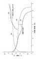
図3は、6個の単電池を内部接続した新電池モジュールに対してサイクル充放電を行った場合の充電時および放電時の電圧特性を示すグラフである。図3において、V30、V31はそれぞれ初期から3サイクル目の充電時および放電時のモジュール電圧を表し、V32、V33はそれぞれ500サイクル後の充電時および放電時のモジュール電圧を表している。図3に示すように、サイクル充放電により、充電メモリー効果および放電メモリー効果が発生している。
【0023】
図4は、6個の単電池を内部接続した新電池モジュールを充電設定および放電設定した後、40℃の環境で20日間放置した場合の充電時および放電時の電圧特性を示すグラフである。図4において、V40、V41はそれぞれ放置前の充電時および放電時のモジュール電圧を、V42、V43はそれぞれ充電設定した後に放置した場合の充電時および放電時のモジュール電圧を、V44、V45はそれぞれ放電設定した後に放置した場合の充電時および放電時のモジュール電圧を表している。図4に示すように、放置により、充電メモリー効果および放電メモリー効果が発生している。
【0024】
次に、電池交換前処理S11を施した交換用電池モジュールを出荷し、交換対象電池モジュールと交換して(S12)、電池パック全体に対して電池交換後処理を施す(S13)。この電池交換後処理S13では、電池容量の100%以上の過充電を行い、交換した電池モジュールと他の電池モジュールの残存容量を揃えるとともに、交換用電池モジュールが長期間放置されていた場合に増大している内部抵抗値を回復させ、電池パック全体としての性能が十分に発揮できるようにする。
【0025】
なお、交換対象電池モジュールの中には、故障して異常モジュールとして特定されているものと、電池特性を回復させることにより再使用可能なものとがあり、この再使用可能な交換対象電池モジュールを再び電池パックとして組み立て(リビルト)、新品相当品として出荷することにより、交換用電池パックの価格の低減と廃棄物の大幅な低減を図ることができる。
【0026】
【発明の効果】
以上説明したように、本発明によれば、低コストで電池交換ができるとともに、電池交換後に、誤った異常検出をすることなく、組電池全体としての性能を最大限に発揮させることが可能になる、という格別な効果を奏する。
【図面の簡単な説明】
【図1】 本発明の一実施形態による二次電池の交換処理ルーチンを示すフローチャート
【図2】 サイクル充放電時におけるSOCの変化幅を示す図
【図3】 新電池モジュールに対してサイクル充放電を行った場合の充電時および放電時の電圧特性を示すグラフ
【図4】 新電池モジュールを充電設定および放電設定した後、40℃の環境で20日間放置した場合の充電時および放電時の電圧特性を示すグラフ
【図5】 従来における新電池モジュールと旧電池モジュールのモジュール電圧の時間変化を示すグラフ
【図6】 従来における新電池モジュールと旧電池モジュールのモジュールSOCの時間変化を示すグラフ
【図7】 従来における新電池モジュールと旧電池モジュールの電圧特性を示すグラフ[0001]
BACKGROUND OF THE INVENTION
The present invention relates to a method of replacing secondary batteries when some of the secondary batteries are deteriorated, have a lifetime, or are out of battery packs configured by connecting a plurality of secondary batteries in series or in parallel. In particular, the present invention relates to a method for replacing a secondary battery mounted on an electric vehicle (PEV) or a hybrid vehicle (HEV).
[0002]
[Prior art]
Recently, in an electric vehicle (PEV) and a so-called hybrid vehicle (HEV) equipped with an engine and an electric motor, as a main power source for driving the electric motor, its high energy density (that is, energy can be stored compactly) and high From the viewpoint of power density, nickel-hydrogen (Ni-MH) secondary batteries are mainly used. In such PEVs and HEVs, for example, a single block type battery module is configured by internally connecting a plurality of single cells so that a sufficient output can be supplied to the electric motor, and a plurality of battery modules are combined to form an assembled battery. Use.
[0003]
In this way, a Ni-MH secondary battery mounted on a PEV or HEV by combining a plurality of battery modules can be used for a longer time if the usage environment is appropriate. In general, one of a plurality of battery modules reaches an abnormality or a life due to a difference or a defect of a component constituting the secondary battery. The battery module that has been determined to be abnormal or has reached the end of its life is replaced with a new battery module, configured again into an assembled battery, and used.
[0004]
[Problems to be solved by the invention]
However, when a battery module that has been determined to be abnormal or has reached the end of its life is removed from an assembled battery that is composed of a plurality of battery modules, and an assembled battery that incorporates a new battery module is mounted on a vehicle, the assembled battery must be replaced. Due to the difference in characteristics between the battery module newly installed in the battery (hereinafter referred to as the new battery module) and the battery module (hereinafter referred to as the old battery module) in the assembled battery used so far, the following problems Will occur.
(1) As shown in FIG. 5, while the vehicle is running, the difference (ΔV) between the voltage value (V60) of the new battery module and the voltage value (V61) of the old battery module increases, and the battery electronic control unit ( (Hereinafter abbreviated as “battery ECU”) may erroneously detect “voltage variation abnormality” for battery protection,
(2) As shown in FIG. 6, when calculating the remaining capacity (SOC: State of Charge) for each battery module, the SOC value (SOC70) of the new battery module and the SOC value (SOC71) of the old battery module Difference (ΔSOC) increases, and the battery ECU may erroneously detect “SOC variation abnormality” for battery protection.
[0005]
The above problem is that the old battery module with a history of use has a memory effect, so as shown in FIG. 7, the voltage characteristic (V81) of the old battery module and the voltage characteristic of the new battery module incorporated at the time of replacement are shown. This is because (V80) does not match.
[0006]
The present invention has been made in view of such a point, and the object thereof is to replace the battery at a low cost and to maximize the performance of the assembled battery as a whole without performing erroneous abnormality detection after the battery replacement. It is in providing the replacement | exchange method of the secondary battery which can be exhibited in this.
[0007]
[Means for Solving the Problems]
In order to achieve the above-described object, the secondary battery replacement method according to the present invention includes replacing a part of secondary batteries of a battery assembly in which a plurality of secondary batteries are electrically connected in series or in parallel with a replacement battery. In the secondary battery replacement method, the replacement target battery is replaced with a replacement battery previously provided with a memory effect.
[0008]
According to this method, after removing the battery to be replaced, by incorporating a replacement battery in which a memory effect substantially the same as the memory effect of the secondary battery used so far is provided to the new secondary battery, It is possible to eliminate the difference between the voltage characteristics of a secondary battery having a history of use and the voltage characteristics of a secondary battery in an unused state, and to make the voltage characteristics of the assembled battery uniform. As a result, even if the assembled battery after battery replacement is mounted on a vehicle, the performance of the entire assembled battery can be maximized without erroneously detecting an abnormality.
[0011]
In addition, as a technique for imparting a memory effect to the secondary battery, cycle charge / discharge is performed, and in particular, the change width of the remaining capacity (SOC) of the secondary battery is limited to an intermediate range of the battery capacity. It is preferable to carry out. In this case, the intermediate range is preferably 20% to 80%.
[0012]
Cycle charge / discharge is performed at a cycle number of 5 to 100, for example, by setting the charge / discharge rate from 0.2 C to 10 C (preferably 2 C to 5 C) and the battery temperature from 25 ° C. to 30 ° C. Moreover, the reason for limiting the SOC change range from 20% to 80% is that if the SOC change range is made larger than this, it becomes close to complete discharge and full charge, and a memory effect can be imparted to the secondary battery. This is because it disappears.
[0013]
Furthermore, as another method for imparting a memory effect to the secondary battery, the initial remaining capacity of the secondary battery is set to 40% or more, and then the battery temperature is maintained at a temperature higher than room temperature and left for two weeks or more. It is preferable to do.
[0014]
In this case, the initial remaining capacity is 40% to 90%, which is higher than the middle level, the storage temperature is 25 ° C to 55 ° C where the self-discharge amount is higher than normal temperature and the self-discharge amount is large, and the storage period is 20% due to self-discharge. A long period of 2 to 12 weeks within a range of not more than% is preferable for imparting a memory effect to the secondary battery.
[0015]
DETAILED DESCRIPTION OF THE INVENTION
The “secondary battery” of the present invention means a single block type battery module in which individual cells or a plurality of unit cells configured as an assembled battery are internally connected. In addition, the “secondary battery” of the present invention is not limited to those included in the assembled battery formed by connecting a plurality of the batteries in series or in parallel, and the assembled batteries are further combined in series or in parallel. Also includes those in the assembled battery system.
[0016]
In the present embodiment, a Ni-MH secondary battery will be described as an example of an alkaline secondary battery. As the Ni-MH secondary battery, in particular, an integrated battery case is formed by integrally connecting six rectangular parallelepiped battery cases at their short sides, and the upper surface opening of each battery case is used as a lid. For example, a single cell (hereinafter referred to as a battery module) in which adjacent cells are internally connected at the upper end of the short side surface between the battery cases is taken as an example.
[0017]
DESCRIPTION OF EXEMPLARY EMBODIMENTS Hereinafter, preferred embodiments of the invention will be described with reference to the drawings.
[0018]
FIG. 1 is a flowchart showing a secondary battery replacement processing routine according to an embodiment of the present invention.
[0019]
In FIG. 1, first, among the battery modules that are transported and stored refrigerated as replacement battery modules, the capacity rank is larger than all battery modules that are not subject to replacement, that is, the maximum capacity rank when incorporated. The product to be selected is selected (S10). Next, a battery replacement pretreatment is performed on the selected replacement battery module (S11). In this battery replacement pre-processing S11, as shown in FIG. 2, the change width of the SOC is used for the replacement battery module before shipping, and the remaining capacity is always used in the intermediate region as in HEV. Considering the history, the battery temperature is limited to 40% to 60%, and the battery temperature is 25 ° C. to 30 ° C. at a charge / discharge rate of 2C (for example, a current value of 13A in the case of a battery module having a battery capacity of 6.5Ah). The battery is charged and discharged for 30 cycles, the initial SOC is set to 70%, the battery temperature is maintained at 45 ° C., and the battery is left for 4 weeks. Adds a memory effect to the battery module.
[0020]
By applying this memory effect, it is possible to achieve consistency between the voltage characteristics of the replacement battery module in the unused state and the voltage characteristics of the battery module having a history of use.
[0021]
Here, the replacement of the battery module not only replaces the battery module determined to be defective, but also if the defective battery module was previously replaced, it was not replaced last time when the battery module was periodically replaced For example, it is possible to replace only the battery module or periodically replace a battery module that is likely to deteriorate when it is known that the assembled battery has a variation in deterioration.
[0022]
FIG. 3 is a graph showing voltage characteristics at the time of charge and discharge when cycle charge / discharge is performed on a new battery module in which six unit cells are internally connected. In FIG. 3, V30 and V31 respectively represent module voltages at the time of charging and discharging in the third cycle from the initial stage, and V32 and V33 respectively represent module voltages at the time of charging and discharging after 500 cycles. As shown in FIG. 3, a charge memory effect and a discharge memory effect are generated by cycle charge / discharge.
[0023]
FIG. 4 is a graph showing voltage characteristics during charging and discharging when a new battery module internally connected with six single cells is set for charging and discharging and then left in an environment of 40 ° C. for 20 days. In FIG. 4, V40 and V41 are module voltages at the time of charging and discharging before leaving, V42 and V43 are module voltages at the time of charging and discharging when left after being set for charging, and V44 and V45 are respectively The module voltage at the time of charging and discharging when left after setting the discharge is shown. As shown in FIG. 4, the charge memory effect and the discharge memory effect are generated by being left unattended.
[0024]
Next, the replacement battery module subjected to the battery replacement pre-processing S11 is shipped and replaced with a replacement target battery module (S12), and the battery replacement process is performed on the entire battery pack (S13). In this battery replacement post-processing S13, overcharge of 100% or more of the battery capacity is performed, the remaining capacity of the replaced battery module and the other battery modules are made uniform, and the increase occurs when the replacement battery module is left unattended for a long time. The internal resistance value is restored and the performance of the battery pack as a whole can be fully exhibited.
[0025]
In addition, some replacement target battery modules are identified as abnormal modules due to failure, and others are reusable by restoring battery characteristics. By assembling (rebuilding) the battery pack again and shipping it as a new equivalent, it is possible to reduce the price of the replacement battery pack and greatly reduce waste.
[0026]
【The invention's effect】
As described above, according to the present invention, the battery can be replaced at low cost, and the performance of the entire assembled battery can be maximized without erroneously detecting the abnormality after the battery replacement. Has the special effect of becoming.
[Brief description of the drawings]
FIG. 1 is a flowchart showing a secondary battery replacement processing routine according to an embodiment of the present invention. FIG. 2 is a diagram showing a change range of SOC during cycle charge / discharge. FIG. 3 is a cycle charge / discharge for a new battery module. Fig. 4 is a graph showing the voltage characteristics during charging and discharging when performing charging. Fig. 4 Voltages during charging and discharging when the new battery module is left in a 40 ° C environment for 20 days after being set for charging and discharging. Graph showing characteristics [Fig. 5] Graph showing time change of module voltage of conventional new battery module and old battery module [Fig. 6] Graph showing time change of module SOC of conventional new battery module and old battery module [Fig. 7] A graph showing voltage characteristics of a conventional new battery module and an old battery module
Claims (5)
Translated fromJapanesePriority Applications (3)
| Application Number | Priority Date | Filing Date | Title |
|---|---|---|---|
| JP2002157768AJP3820184B2 (en) | 2002-05-30 | 2002-05-30 | Replacing the secondary battery |
| US10/448,389US20030224241A1 (en) | 2002-05-30 | 2003-05-30 | Secondary cell replacing method |
| US12/615,095US7998609B2 (en) | 2002-05-30 | 2009-11-09 | Secondary cell replacing method |
Applications Claiming Priority (1)
| Application Number | Priority Date | Filing Date | Title |
|---|---|---|---|
| JP2002157768AJP3820184B2 (en) | 2002-05-30 | 2002-05-30 | Replacing the secondary battery |
Publications (2)
| Publication Number | Publication Date |
|---|---|
| JP2003346909A JP2003346909A (en) | 2003-12-05 |
| JP3820184B2true JP3820184B2 (en) | 2006-09-13 |
Family
ID=29561526
Family Applications (1)
| Application Number | Title | Priority Date | Filing Date |
|---|---|---|---|
| JP2002157768AExpired - Fee RelatedJP3820184B2 (en) | 2002-05-30 | 2002-05-30 | Replacing the secondary battery |
Country Status (2)
| Country | Link |
|---|---|
| US (2) | US20030224241A1 (en) |
| JP (1) | JP3820184B2 (en) |
Cited By (1)
| Publication number | Priority date | Publication date | Assignee | Title |
|---|---|---|---|---|
| US8362749B2 (en) | 2008-05-19 | 2013-01-29 | Panasonic Ev Energy Co., Ltd. | Method for exchanging rechargeable batteries |
Families Citing this family (67)
| Publication number | Priority date | Publication date | Assignee | Title |
|---|---|---|---|---|
| JP4134704B2 (en)* | 2002-12-02 | 2008-08-20 | トヨタ自動車株式会社 | Replacing the secondary battery |
| US9255955B2 (en) | 2003-09-05 | 2016-02-09 | Midtronics, Inc. | Method and apparatus for measuring a parameter of a vehicle electrical system |
| US9018958B2 (en) | 2003-09-05 | 2015-04-28 | Midtronics, Inc. | Method and apparatus for measuring a parameter of a vehicle electrical system |
| JP2005238969A (en)* | 2004-02-26 | 2005-09-08 | Mitsubishi Heavy Ind Ltd | On-vehicle electricity storage device, and electricity storage device replacing stand |
| US9496720B2 (en) | 2004-08-20 | 2016-11-15 | Midtronics, Inc. | System for automatically gathering battery information |
| JP5319081B2 (en)* | 2007-05-22 | 2013-10-16 | プライムアースEvエナジー株式会社 | Manufacturing method of battery pack with controller |
| JP5096806B2 (en)* | 2007-06-20 | 2012-12-12 | プライムアースEvエナジー株式会社 | Manufacturing method of battery pack |
| JP5011007B2 (en)* | 2007-07-04 | 2012-08-29 | プライムアースEvエナジー株式会社 | Battery pack and manufacturing method thereof |
| JP5096817B2 (en)* | 2007-07-10 | 2012-12-12 | プライムアースEvエナジー株式会社 | Manufacturing method of reconfigurable battery pack |
| US9274157B2 (en) | 2007-07-17 | 2016-03-01 | Midtronics, Inc. | Battery tester for electric vehicle |
| GB2463829B (en) | 2007-07-17 | 2012-11-21 | Midtronics Inc | Battery tester for electric vehicle |
| US9588185B2 (en) | 2010-02-25 | 2017-03-07 | Keith S. Champlin | Method and apparatus for detecting cell deterioration in an electrochemical cell or battery |
| WO2011109343A2 (en) | 2010-03-03 | 2011-09-09 | Midtronics, Inc. | Monitor for front terminal batteries |
| US9166261B2 (en)* | 2010-03-31 | 2015-10-20 | Primearth Ev Energy Co., Ltd. | Method for reusing secondary battery |
| WO2011132300A1 (en)* | 2010-04-23 | 2011-10-27 | トヨタ自動車株式会社 | Method for restoring secondary battery, system for restoring secondary battery and vehicle equipped with same |
| US9229062B2 (en) | 2010-05-27 | 2016-01-05 | Midtronics, Inc. | Electronic storage battery diagnostic system |
| US10046649B2 (en) | 2012-06-28 | 2018-08-14 | Midtronics, Inc. | Hybrid and electric vehicle battery pack maintenance device |
| US20110300416A1 (en) | 2010-06-03 | 2011-12-08 | Bertness Kevin I | Battery pack maintenance for electric vehicle |
| US8738309B2 (en)* | 2010-09-30 | 2014-05-27 | Midtronics, Inc. | Battery pack maintenance for electric vehicles |
| US11740294B2 (en) | 2010-06-03 | 2023-08-29 | Midtronics, Inc. | High use battery pack maintenance |
| US9419311B2 (en) | 2010-06-18 | 2016-08-16 | Midtronics, Inc. | Battery maintenance device with thermal buffer |
| CN103079869B (en)* | 2010-06-23 | 2015-06-10 | 丰田自动车株式会社 | Vehicle control device and vehicle control method |
| US9201120B2 (en) | 2010-08-12 | 2015-12-01 | Midtronics, Inc. | Electronic battery tester for testing storage battery |
| JP2012113856A (en)* | 2010-11-22 | 2012-06-14 | Toyota Motor Corp | Method of replacing power supply stack, control device, and control program |
| CN102381172B (en)* | 2011-09-22 | 2014-03-12 | 上海中科深江电动车辆有限公司 | Electrical storage device and electric vehicle carrying electrical storage device |
| WO2013070850A2 (en) | 2011-11-10 | 2013-05-16 | Midtronics, Inc. | Battery pack tester |
| JP5553177B2 (en)* | 2011-11-24 | 2014-07-16 | トヨタ自動車株式会社 | Secondary battery reuse method, vehicle drive power supply, and vehicle |
| US11325479B2 (en) | 2012-06-28 | 2022-05-10 | Midtronics, Inc. | Hybrid and electric vehicle battery maintenance device |
| US9851411B2 (en) | 2012-06-28 | 2017-12-26 | Keith S. Champlin | Suppressing HF cable oscillations during dynamic measurements of cells and batteries |
| US9244100B2 (en) | 2013-03-15 | 2016-01-26 | Midtronics, Inc. | Current clamp with jaw closure detection |
| JP5741619B2 (en)* | 2013-03-21 | 2015-07-01 | トヨタ自動車株式会社 | Secondary battery management system, secondary battery management device, and secondary battery management method |
| US9312575B2 (en) | 2013-05-16 | 2016-04-12 | Midtronics, Inc. | Battery testing system and method |
| US10843574B2 (en) | 2013-12-12 | 2020-11-24 | Midtronics, Inc. | Calibration and programming of in-vehicle battery sensors |
| EP2897229A1 (en) | 2014-01-16 | 2015-07-22 | Midtronics, Inc. | Battery clamp with endoskeleton design |
| JP6048448B2 (en)* | 2014-05-22 | 2016-12-21 | トヨタ自動車株式会社 | Method for determining reusable product application of used secondary battery and reconfiguring assembled battery reassembled product |
| US10473555B2 (en) | 2014-07-14 | 2019-11-12 | Midtronics, Inc. | Automotive maintenance system |
| US10222397B2 (en) | 2014-09-26 | 2019-03-05 | Midtronics, Inc. | Cable connector for electronic battery tester |
| WO2016123075A1 (en) | 2015-01-26 | 2016-08-04 | Midtronics, Inc. | Alternator tester |
| US9966676B2 (en) | 2015-09-28 | 2018-05-08 | Midtronics, Inc. | Kelvin connector adapter for storage battery |
| US10608353B2 (en) | 2016-06-28 | 2020-03-31 | Midtronics, Inc. | Battery clamp |
| US11054480B2 (en) | 2016-10-25 | 2021-07-06 | Midtronics, Inc. | Electrical load for electronic battery tester and electronic battery tester including such electrical load |
| US12320857B2 (en) | 2016-10-25 | 2025-06-03 | Midtronics, Inc. | Electrical load for electronic battery tester and electronic battery tester including such electrical load |
| US11088402B2 (en) | 2017-01-12 | 2021-08-10 | StoreDot Ltd. | Extending cycling lifetime of fast-charging lithium ion batteries |
| US10122042B2 (en)* | 2017-01-12 | 2018-11-06 | StoreDot Ltd. | Increasing cycling lifetime of fast-charging lithium ion batteries |
| US10833521B2 (en)* | 2017-01-12 | 2020-11-10 | StoreDot Ltd. | Formation method for preparing a fast-charging lithium ion cell |
| US11152602B2 (en)* | 2017-01-12 | 2021-10-19 | StoreDot Ltd. | Using formation parameters to extend the cycling lifetime of lithium ion batteries |
| JP7032110B2 (en)* | 2017-11-21 | 2022-03-08 | トヨタ自動車株式会社 | Exchange charge setting device and exchange charge setting system |
| JP6911747B2 (en)* | 2017-12-25 | 2021-07-28 | トヨタ自動車株式会社 | Battery information processing device, battery manufacturing support device, assembled battery, battery information processing method, and assembled battery manufacturing method |
| JP6745867B2 (en)* | 2017-12-29 | 2020-08-26 | ゴゴロ インク | System and related methods for managing batteries |
| CN108680868B (en)* | 2018-05-28 | 2020-09-11 | 天津市捷威动力工业有限公司 | A kind of battery pack cycle test consistency analysis method |
| US11513160B2 (en) | 2018-11-29 | 2022-11-29 | Midtronics, Inc. | Vehicle battery maintenance device |
| CN109622426A (en)* | 2018-12-27 | 2019-04-16 | 银隆新能源股份有限公司 | A kind of battery consistency screening technique and battery consistency screening plant |
| US11228195B2 (en) | 2019-04-21 | 2022-01-18 | StoreDot Ltd. | Lithium ion devices, operated with set operative capacity |
| US11566972B2 (en) | 2019-07-31 | 2023-01-31 | Midtronics, Inc. | Tire tread gauge using visual indicator |
| US11214171B2 (en)* | 2019-09-13 | 2022-01-04 | Ford Global Technologies, Llc | Mixed battery pack control |
| US11545839B2 (en) | 2019-11-05 | 2023-01-03 | Midtronics, Inc. | System for charging a series of connected batteries |
| US11668779B2 (en) | 2019-11-11 | 2023-06-06 | Midtronics, Inc. | Hybrid and electric vehicle battery pack maintenance device |
| US11474153B2 (en) | 2019-11-12 | 2022-10-18 | Midtronics, Inc. | Battery pack maintenance system |
| DE102020216599A1 (en) | 2019-12-31 | 2021-07-01 | Midtronics, Inc. | Intelligent module interface for a battery maintenance device |
| US11973202B2 (en) | 2019-12-31 | 2024-04-30 | Midtronics, Inc. | Intelligent module interface for battery maintenance device |
| US11486930B2 (en) | 2020-01-23 | 2022-11-01 | Midtronics, Inc. | Electronic battery tester with battery clamp storage holsters |
| US11133690B1 (en)* | 2020-06-02 | 2021-09-28 | Inventus Power, Inc. | Large-format battery management system |
| CN112290109B (en)* | 2020-10-30 | 2022-03-15 | 重庆长安新能源汽车科技有限公司 | Lithium ion battery balance maintenance method based on cloud platform |
| JP7739812B2 (en)* | 2021-07-27 | 2025-09-17 | トヨタ自動車株式会社 | How to replace the battery block in a battery pack |
| US12330513B2 (en) | 2022-02-14 | 2025-06-17 | Midtronics, Inc. | Battery maintenance device with high voltage connector |
| US12392833B2 (en) | 2022-05-09 | 2025-08-19 | Midtronics, Inc. | Electronic battery tester |
| US20240408950A1 (en)* | 2023-06-12 | 2024-12-12 | Ford Global Technologies, Llc | Electrified vehicle including battery pack with modular configuration |
Family Cites Families (9)
| Publication number | Priority date | Publication date | Assignee | Title |
|---|---|---|---|---|
| JPH02101937A (en) | 1988-10-06 | 1990-04-13 | Victor Co Of Japan Ltd | Power supply |
| JP2979939B2 (en)* | 1993-12-27 | 1999-11-22 | 株式会社日立製作所 | Operation method of secondary battery system |
| JP3674144B2 (en)* | 1996-04-30 | 2005-07-20 | ヤマハ発動機株式会社 | Electric vehicle power supply method and apparatus |
| JP3351683B2 (en)* | 1996-06-21 | 2002-12-03 | 日野自動車株式会社 | In-vehicle battery control device |
| KR980006710A (en)* | 1996-06-29 | 1998-03-30 | 김광호 | Battery charger to prevent memory effect |
| JP3750318B2 (en)* | 1997-11-14 | 2006-03-01 | 日産自動車株式会社 | Module charger / discharger |
| JPH11317243A (en) | 1998-04-30 | 1999-11-16 | Nissan Motor Co Ltd | Capacity calculation method when replacing battery for automobile |
| JP4001708B2 (en)* | 2000-04-28 | 2007-10-31 | 松下電器産業株式会社 | Replacing the secondary battery |
| US6586909B1 (en)* | 2001-12-21 | 2003-07-01 | Ron Trepka | Parallel battery charging device |
- 2002
- 2002-05-30JPJP2002157768Apatent/JP3820184B2/ennot_activeExpired - Fee Related
- 2003
- 2003-05-30USUS10/448,389patent/US20030224241A1/ennot_activeAbandoned
- 2009
- 2009-11-09USUS12/615,095patent/US7998609B2/ennot_activeExpired - Fee Related
Cited By (1)
| Publication number | Priority date | Publication date | Assignee | Title |
|---|---|---|---|---|
| US8362749B2 (en) | 2008-05-19 | 2013-01-29 | Panasonic Ev Energy Co., Ltd. | Method for exchanging rechargeable batteries |
Also Published As
| Publication number | Publication date |
|---|---|
| US20100052616A1 (en) | 2010-03-04 |
| JP2003346909A (en) | 2003-12-05 |
| US20030224241A1 (en) | 2003-12-04 |
| US7998609B2 (en) | 2011-08-16 |
Similar Documents
| Publication | Publication Date | Title |
|---|---|---|
| JP3820184B2 (en) | Replacing the secondary battery | |
| JP4134704B2 (en) | Replacing the secondary battery | |
| US9166261B2 (en) | Method for reusing secondary battery | |
| EP1150132B1 (en) | Method of replacing secondary battery | |
| CN110509817B (en) | Vehicle and battery equalization control method and device | |
| CN102056761B (en) | Charging control device and vehicles equipped with it | |
| US10181733B2 (en) | Apparatus and method of balancing voltages between battery racks | |
| JP5519371B2 (en) | Reuse method of secondary battery | |
| CN109655753B (en) | Estimation method of SOC of battery pack | |
| KR20190088845A (en) | Battery management system and battery cell array | |
| KR20120135295A (en) | Method for screening used secondary battery, rebuilt battery pack, vehicle and battery operated device incorporating same, and method for manufacturing rebuilt battery pack | |
| JP2009277627A (en) | Secondary battery exchanging method | |
| JP3367382B2 (en) | Lithium ion secondary battery | |
| Sanghai et al. | Refurbished and repower: second life of batteries from electric vehicles for stationary application | |
| JP4956881B2 (en) | How to replace an abnormal battery | |
| JP7652741B2 (en) | Battery control device, power storage system, and battery control method | |
| JP4615771B2 (en) | Assembled battery | |
| Hobbs et al. | Development of optimized fast charge algorithms for lead acid batteries | |
| Chou et al. | Battery Pack Reliability and Endurance Enhancement for Electric Vehicles by Dynamic Reconfiguration | |
| Ahir et al. | Impact of battery cell imbalance on the voltage behavior of commercial Ni-MH EV/HEV battery modules | |
| KR20250124645A (en) | Apparatus for controlling vehicle and method thereof | |
| CN119582403A (en) | A multi-battery device and method for extending usage time and battery life | |
| KR20110001205U (en) | Circuit for equlization of voltage of batteries | |
| JP2008218370A (en) | Five-cell lead-acid battery |
Legal Events
| Date | Code | Title | Description |
|---|---|---|---|
| A621 | Written request for application examination | Free format text:JAPANESE INTERMEDIATE CODE: A621 Effective date:20041006 | |
| A977 | Report on retrieval | Free format text:JAPANESE INTERMEDIATE CODE: A971007 Effective date:20051212 | |
| A131 | Notification of reasons for refusal | Free format text:JAPANESE INTERMEDIATE CODE: A131 Effective date:20060330 | |
| A521 | Request for written amendment filed | Free format text:JAPANESE INTERMEDIATE CODE: A523 Effective date:20060515 | |
| TRDD | Decision of grant or rejection written | ||
| A01 | Written decision to grant a patent or to grant a registration (utility model) | Free format text:JAPANESE INTERMEDIATE CODE: A01 Effective date:20060613 | |
| A61 | First payment of annual fees (during grant procedure) | Free format text:JAPANESE INTERMEDIATE CODE: A61 Effective date:20060616 | |
| R150 | Certificate of patent or registration of utility model | Free format text:JAPANESE INTERMEDIATE CODE: R150 Ref document number:3820184 Country of ref document:JP Free format text:JAPANESE INTERMEDIATE CODE: R150 | |
| FPAY | Renewal fee payment (event date is renewal date of database) | Free format text:PAYMENT UNTIL: 20090623 Year of fee payment:3 | |
| FPAY | Renewal fee payment (event date is renewal date of database) | Free format text:PAYMENT UNTIL: 20100623 Year of fee payment:4 | |
| R250 | Receipt of annual fees | Free format text:JAPANESE INTERMEDIATE CODE: R250 | |
| FPAY | Renewal fee payment (event date is renewal date of database) | Free format text:PAYMENT UNTIL: 20110623 Year of fee payment:5 | |
| R250 | Receipt of annual fees | Free format text:JAPANESE INTERMEDIATE CODE: R250 | |
| FPAY | Renewal fee payment (event date is renewal date of database) | Free format text:PAYMENT UNTIL: 20110623 Year of fee payment:5 | |
| FPAY | Renewal fee payment (event date is renewal date of database) | Free format text:PAYMENT UNTIL: 20120623 Year of fee payment:6 | |
| R250 | Receipt of annual fees | Free format text:JAPANESE INTERMEDIATE CODE: R250 | |
| FPAY | Renewal fee payment (event date is renewal date of database) | Free format text:PAYMENT UNTIL: 20130623 Year of fee payment:7 | |
| R250 | Receipt of annual fees | Free format text:JAPANESE INTERMEDIATE CODE: R250 | |
| FPAY | Renewal fee payment (event date is renewal date of database) | Free format text:PAYMENT UNTIL: 20130623 Year of fee payment:7 | |
| R250 | Receipt of annual fees | Free format text:JAPANESE INTERMEDIATE CODE: R250 | |
| R250 | Receipt of annual fees | Free format text:JAPANESE INTERMEDIATE CODE: R250 | |
| R250 | Receipt of annual fees | Free format text:JAPANESE INTERMEDIATE CODE: R250 | |
| R250 | Receipt of annual fees | Free format text:JAPANESE INTERMEDIATE CODE: R250 | |
| R250 | Receipt of annual fees | Free format text:JAPANESE INTERMEDIATE CODE: R250 | |
| R250 | Receipt of annual fees | Free format text:JAPANESE INTERMEDIATE CODE: R250 | |
| R250 | Receipt of annual fees | Free format text:JAPANESE INTERMEDIATE CODE: R250 | |
| R250 | Receipt of annual fees | Free format text:JAPANESE INTERMEDIATE CODE: R250 | |
| LAPS | Cancellation because of no payment of annual fees |