JP3818204B2 - Radar equipment - Google Patents
Radar equipmentDownload PDFInfo
- Publication number
- JP3818204B2 JP3818204B2JP2002109532AJP2002109532AJP3818204B2JP 3818204 B2JP3818204 B2JP 3818204B2JP 2002109532 AJP2002109532 AJP 2002109532AJP 2002109532 AJP2002109532 AJP 2002109532AJP 3818204 B2JP3818204 B2JP 3818204B2
- Authority
- JP
- Japan
- Prior art keywords
- signal
- radar
- time
- change point
- transmission
- Prior art date
- Legal status (The legal status is an assumption and is not a legal conclusion. Google has not performed a legal analysis and makes no representation as to the accuracy of the status listed.)
- Expired - Fee Related
Links
- 230000005540biological transmissionEffects0.000claimsdescription32
- 238000005259measurementMethods0.000claimsdescription17
- 238000001514detection methodMethods0.000claimsdescription6
- 230000007274generation of a signal involved in cell-cell signalingEffects0.000description6
- 238000010586diagramMethods0.000description5
- 230000004069differentiationEffects0.000description3
- 230000000630rising effectEffects0.000description3
- 238000013075data extractionMethods0.000description2
- 230000008034disappearanceEffects0.000description2
- 238000012544monitoring processMethods0.000description2
- 238000007493shaping processMethods0.000description2
- 238000004904shorteningMethods0.000description2
Images


Landscapes
- Traffic Control Systems (AREA)
- Radar Systems Or Details Thereof (AREA)
Description
Translated fromJapanese【0001】
【発明の属する技術分野】
本発明は、パルス状のレーダ波を送受信してターゲットの検出を行うレーダ装置に関する。
【0002】
【従来の技術】
従来より、レーダ波を送受信してターゲットを検出するレーダ装置の一つとして、パルス方式のレーダ装置(以下「パルスレーダ」と称する)が知られている。
【0003】
ここで図3は、パルスレーダ100の一般的な構成を表すブロック図である。
図3に示すように、パルスレーダは、送信アンテナ11,スイッチ12,発振器13からなる送信部110と、受信アンテナ21,ローノイズアンプ22,ミキサ23,ローカル発振器24,IFアンプ25,検波器26,コンパレータ29からなる受信部120と、パルス発生器31,時間差計測回路32からなる制御部130とにより構成されている。
【0004】
そして、送信部110では、制御部130のパルス発生器31が発生させた送信パルス信号Psに従ってスイッチ12が作動し、その送信パルス信号Psのパルス幅の期間だけ、発振器13が生成した高周波信号を送信アンテナ11に供給することにより、送信アンテナ11にパルス状のレーダ波を送信させる。
【0005】
また、受信部120では、受信アンテナ21が受信したレーダ波の受信信号を、ローノイズアンプ22が増幅し、これをローカル発振器24からのローカル信号とミキサ23にて混合することにより、中間周波数帯の信号(IF信号)にダウンコンバートする。そのIF信号を、IFアンプ25にて増幅した後、検波器26が包絡線検波を行うことで復調し、更にこの復調した信号をコンパレータ29にて波形整形することで受信パルス信号Prを生成する。
【0006】
また、制御部130では、パルス発生器31が、送信パルス信号Psを送信部110に供給すると共に時間差計測回路32にも供給し、時間差計測回路32は、パルス発生器31からの送信パルス信号Psと、受信部120からの受信パルス信号Prとの時間差を、レーダ波がターゲットまでの距離を往復するのに要した往復時間として計測する。
【0007】
そして、この往復時間の計測結果tから、次式(1)を用いてターゲットまでの距離Rを求めている。
R=C・(t−t0)/2 (1)
但し、Cは光速でC=3×10⁸m/s、t0は回路内の信号遅延である。
【0008】
【発明が解決しようとする課題】
ところで、パルスレーダを、例えば、周辺監視用車載レーダとして使用する場合は、衝突判定を行う必要があるため、高い距離分解能(少なくとも数十cm)が必要とされる。そして、パルスレーダでは、レーダ波(送信パルス信号Ps)のパルス幅を短くするほど距離分解能を高めることができるが、その一方で、パルス幅を短くするほどレーダ波の占有帯域幅は増大する。例えば、10cm程度の距離分解能を得ようとすると、その占有帯域幅は数GHzにも達する。
【0009】
これに対して、特定小電力無線局移動体検知センサ用無線設備に関する規格(ARIB STD−T73)では、このような車載レーダに適用される24GHz帯での帯域条件が76MHz以下となっている。
つまり、この帯域条件を満たそうとすると、距離分解能が数mオーダーとなってしまい、車載レーダ等、高い分解能を必要とする用途には、使用することができないという問題があった。
【0010】
即ち、二つのターゲットが存在し、各ターゲットまでの距離差が距離分解能より短い場合、図4に示すように、これらのターゲットからの反射波は、送信パルス信号Psのパルス幅より短い時間間隔で受信され、その受信信号を検波器26にて復調してなる復調信号は、各ターゲットからの信号が互いに重なり合ったものとなる。そして、この信号を、コンパレータ29にて波形整形すると、パルス幅の大きい単一の受信パルス信号Prが生成され、遅れて受信した反射波の受信タイミングが消失してしまい、その反射元となったターゲットの距離を検出できないのである。
【0011】
本発明は、上記問題点を解決するために、パルス状のレーダ波を送受信することにより、ターゲットの距離を検出するレーダ装置において、レーダ波の占有帯域幅を増大させることなく、距離分解能を向上させることを目的とする。
【0012】
【課題を解決するための手段】
上記目的を達成するための発明である請求項1記載のレーダ装置では、送受信手段が、入力された送信パルス信号に従ってパルス状のレーダ波を送信し、受信したレーダ波に基づく復調信号を生成すると、変化点検出手段が、その復調信号の信号レベルの変化点を検出し、計時手段が、送信パルス信号によるレーダ波の送信タイミングから、変化点検出手段にて検出された変化点までの時間を計測する。そして、時間データ抽出手段が、その計測結果の中を、送信パルス信号のパルス幅だけ時間差を有するもの同士で組合せ、組み合わされた一対の計測結果のうち値の小さい方を、ターゲットまでのレーダ波の往復時間を表す時間データとして抽出する。
【0013】
つまり、送信パルス信号のパルス幅より短い間隔で受信された二つのレーダ波に基づく復調信号は、二つのパルスを合成した波形を有しており、先に受信したレーダ波の受信タイミングで信号が立ち上がり、後で受信したレーダ波の受信タイミングで信号レベルが変化し、その後、先に受信したレーダ波の消失タイミングで信号レベルが再び変化し、後で受信したレーダ波の消失タイミングで信号が立ち下がる。
【0014】
このように、復調信号の信号レベルが変化する変化点には、両レーダ波の受信タイミングが含まれているため、計時手段に、これらの変化点のタイミングで計測を行わせることにより、距離分解能以下の距離差にある複数のターゲットの距離を個々に検出することが可能となる。
【0015】
従って、本発明のレーダ装置によれば、レーダ波のパルス幅を短くしてレーダ波の占有帯域幅を増大させることなく、実質的な距離分解能を向上させることができる。
【0016】
なお、復調信号は、各パルスの立ち上がりエッジと立ち下がりエッジにて変化点が現れるため、対になる相手のない孤立した変化点はノイズであると考えられるが、本発明のレーダ装置によれば、時間データ抽出手段がこれを除去するため、時間データの信頼性を向上させることができる。
【0017】
また、変化点検出手段としては、例えば請求項2記載のように、微分回路を用いることができる。
【0018】
【発明の実施の形態】
以下に本発明の実施形態を図面と共に説明する。
図1は、本発明が適用された周辺監視用車載レーダ(以下単に「レーダ装置」という)の構成を示すブロック図である。なお、本実施形態のレーダ装置は、図3に示す従来装置とは、一部構成が異なっているだけであるため、同一の構成部分については同一符号を付して説明を省略し、構成の相異する部分を中心に説明する。
【0019】
本実施形態のレーダ装置1は、図1に示すように、送信アンテナ11,スイッチ12,発振器13からなる送信部10と、受信アンテナ21,ローノイズアンプ22,ミキサ23,ローカル発振器24,IFアンプ25,検波器26,微分回路27,トリガ信号生成回路28からなる受信部20と、パルス発生器31,時間差計測回路32,往復時間選択部33からなる制御部30とにより構成されている。
【0020】
つまり、従来装置100と比較して、受信部20では、コンパレータ29の代わりに微分回路27,トリガ信号生成回路28が設けられ、制御部30では、往復時間選択部33が追加されている。
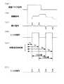
そして、図2に示すように、受信部20では、検波器26によって復調された復調信号を、微分回路27が微分することにより、復調信号の信号レベルが瞬時的に変化する変化点を表す微分信号を生成し、トリガ信号生成回路28が、この微分信号が表す変化点のタイミング毎に信号レベルが反転するトリガ信号を生成する。
【0021】
このトリガ信号に基づき、制御部30の時間差計測回路32では、送信パルス信号Psの立ち上がりエッジから、トリガ信号の信号レベルが反転する各エッジ(即ち、復調信号の変化点)までの時間(T1〜T4)をそれぞれ測定し、その測定結果に基づき、往復時間選択部33は、各測定結果を、両者の時間差が送信パルス信号Psのパルス幅とほぼ同じとなるようなもの同士で組み合わせ、その組み合わせた一対の測定時間のうち値の小さい方を、レーダ波がターゲットまでの距離を往復するのに要した往復時間を表す時間データとして抽出する。
【0022】
即ち、図2では、T1とT3、T2とT4が組み合わされ、そのうち値の小さいT1,T2が、時間データとして抽出されることになる。
以上説明したように、本実施形態のレーダ装置1では、レーダ波の受信信号(IF信号)を復調してなる復調信号を、単純に波形整形するのではなく、復調信号の信号レベルが変化する変化点を抽出し、この変化点のタイミングで、時間の計測を行うようにされている。つまり、複数のレーダ波が重なり合って受信された時には、レーダ波の重なりが始まったタイミング(即ち、後で受信したレーダ波の受信タイミング)や重なりが終わったタイミング(即ち、先に受信したレーダ波が消滅したタイミング)も、この変化点として検出される。
【0023】
このように、本実施形態のレーダ装置1によれば、複数のレーダ波が重なり合って受信されたとしても、各レーダ波の受信タイミングを個別に抽出でき、それぞれについて時間測定を行うことが可能なため、レーダ波(送信パルス信号Ps)のパルス幅を短くすることなく、実質的な距離分解能を向上させることができる。
【0024】
しかも本実施形態のレーダ装置1では、送信パルス信号Psのパルス幅分の時間差を有する測定結果を組み合わせることにより、組み合わせる相手のない孤立したタイミングがノイズとして除去されるため、時間データの信頼性を向上させることができる。
【0025】
なお、本実施形態において、トリガ信号生成回路28は、微分信号のタイミングで信号レベルが反転するトリガ信号を生成しているが、例えば、図2(f)に示すように、微分信号を整流して波形整形することで生成される信号を、トリガ信号としてもよい。但し、この場合、時間差計測回路32は、トリガ信号の立ち上がりエッジのみを時間差計測に用いるように構成する必要がある。
【0026】
また、上記実施形態において、送信部10及び受信部20の受信アンテナ21〜検波器26までの構成が送受信手段、微分回路27,トリガ信号生成回路28が変化点検出手段、時間差計測回路32が計時手段、往復時間選択部33が時間データ抽出手段に相当する。
【図面の簡単な説明】
【図1】 実施形態のレーダ装置の構成を表すブロック図である。
【図2】 主要部の動作を説明するためのタイミング図である。
【図3】 従来装置の構成を表すブロック図である。
【図4】 従来装置の問題点を説明するためのタイミング図である。
【符号の説明】
1…レーダ装置、10…送信部、11…送信アンテナ、12…スイッチ、13…発振器、20…受信部、21…受信アンテナ、22…ローノイズアンプ、23…ミキサ、24…ローカル発振器、25…IFアンプ、26…検波器、27…微分回路、28…トリガ信号生成回路、28…波形整形回路、29…コンパレータ、30…制御部、31…パルス発生器、32…時間差計測回路、33…往復時間選択部。[0001]
BACKGROUND OF THE INVENTION
The present invention relates to a radar apparatus that detects a target by transmitting and receiving pulsed radar waves.
[0002]
[Prior art]
Conventionally, a pulse-type radar device (hereinafter referred to as “pulse radar”) is known as one of radar devices that detect a target by transmitting and receiving radar waves.
[0003]
Here, FIG. 3 is a block diagram showing a general configuration of the pulse radar 100.
As shown in FIG. 3, the pulse radar includes a
[0004]
In the
[0005]
Further, in the receiving unit 120, the radar signal received by the
[0006]
In the control unit 130, the
[0007]
And the distance R to a target is calculated | required from the measurement result t of this round-trip time using following Formula (1).
R = C · (t−t0) / 2 (1)
However, C is the speed of light, C = 3 × 10⁸ m / s, and t0 is a signal delay in the circuit.
[0008]
[Problems to be solved by the invention]
By the way, when the pulse radar is used as, for example, an on-vehicle radar for periphery monitoring, it is necessary to perform a collision determination, and thus high distance resolution (at least several tens of centimeters) is required. In the pulse radar, the distance resolution can be increased as the pulse width of the radar wave (transmission pulse signal Ps) is shortened, while the occupied bandwidth of the radar wave is increased as the pulse width is shortened. For example, when trying to obtain a distance resolution of about 10 cm, the occupied bandwidth reaches several GHz.
[0009]
On the other hand, in the standard (ARIB STD-T73) regarding the radio equipment for the specific low power radio station mobile object detection sensor, the band condition in the 24 GHz band applied to such an in-vehicle radar is 76 MHz or less.
In other words, if this band condition is satisfied, the distance resolution is on the order of several meters, and there is a problem that it cannot be used for applications that require high resolution such as in-vehicle radar.
[0010]
That is, when there are two targets and the distance difference to each target is shorter than the distance resolution, the reflected waves from these targets are transmitted at a time interval shorter than the pulse width of the transmission pulse signal Ps as shown in FIG. A demodulated signal that is received and demodulated by the
[0011]
In order to solve the above problems, the present invention improves the distance resolution without increasing the occupied bandwidth of the radar wave in the radar device that detects the target distance by transmitting and receiving pulsed radar waves. The purpose is to let you.
[0012]
[Means for Solving the Problems]
In the radar apparatus according to
[0013]
That is, the demodulated signal based on two radar waves received at an interval shorter than the pulse width of the transmission pulse signal has a waveform obtained by combining the two pulses, and the signal is received at the reception timing of the previously received radar wave. The signal level changes at the reception timing of the radar wave that was received later, and then the signal level changed again at the disappearance timing of the radar wave that was received earlier, and the signal rises at the disappearance timing of the radar wave that was received later. Go down.
[0014]
In this way, the change point where the signal level of the demodulated signal changes includes the reception timing of both radar waves, so that the time resolution is measured at the timing of these change points, so that the distance resolution It becomes possible to individually detect the distances of a plurality of targets having the following distance difference.
[0015]
Therefore, according to the radar apparatus of the present invention, it is possible to improve the substantial distance resolution without shortening the pulse width of the radar wave and increasing the occupied bandwidth of the radar wave.
[0016]
In the demodulated signal, change points appear at the rising edge and falling edge of each pulse. Therefore, it is considered that an isolated change point with no counterpart is a noise,but according to the radar apparatus of the present invention, Since the time data extraction means removes this, the reliability ofthe time data can be improved.
[0017]
As the change point detecting means, for example, a differentiating circuit can be used as described in
[0018]
DETAILED DESCRIPTION OF THE INVENTION
Embodiments of the present invention will be described below with reference to the drawings.
FIG. 1 is a block diagram showing a configuration of an on-vehicle monitoring radar (hereinafter simply referred to as “radar device”) to which the present invention is applied. Note that the radar apparatus of this embodiment is only partially different from the conventional apparatus shown in FIG. 3, and therefore, the same components are denoted by the same reference numerals and the description thereof is omitted. The description will focus on the differences.
[0019]
As shown in FIG. 1, the
[0020]
That is, as compared with the conventional apparatus 100, the receiving
As shown in FIG. 2, in the receiving
[0021]
Based on this trigger signal, the time
[0022]
That is, in FIG. 2, T1 and T3 and T2 and T4 are combined, and T1 and T2 having a small value are extracted as time data.
As described above, in the
[0023]
Thus, according to the
[0024]
Moreover, in the
[0025]
In the present embodiment, the trigger signal generation circuit 28 generates a trigger signal whose signal level is inverted at the timing of the differential signal. For example, as shown in FIG. The signal generated by shaping the waveform may be used as a trigger signal. However, in this case, the time
[0026]
Moreover, in the said embodiment, the structure from the receiving antenna 21-the
[Brief description of the drawings]
FIG. 1 is a block diagram illustrating a configuration of a radar apparatus according to an embodiment.
FIG. 2 is a timing chart for explaining the operation of the main part.
FIG. 3 is a block diagram showing a configuration of a conventional apparatus.
FIG. 4 is a timing diagram for explaining problems of the conventional device.
[Explanation of symbols]
DESCRIPTION OF
Claims (2)
Translated fromJapanese該送受信手段が生成する復調信号の信号レベルの変化点を検出する変化点検出手段と、
前記送信パルス信号によるレーダ波の送信タイミングから、前記変化点検出手段が検出した各変化点までの時間を計測する計時手段と、
該計時手段での計測結果を、前記送信パルス信号のパルス幅だけ時間差を有するもの同士で組合せ、組み合わされた一対の計測結果のうち値の小さい方を、ターゲットまでのレーダ波の往復時間を表す時間データとして抽出する時間データ抽出手段と、
を備えることを特徴とするレーダ装置。Transmitting and receiving means for transmitting a pulsed radar wave by inputting a transmission pulse signal and generating a demodulated signal obtained by demodulating the received signal when receiving the radar wave;
Change point detection means for detecting a change point of the signal level of the demodulated signal generated by the transmission / reception means;
Time measuring means for measuring the time from the transmission timing of the radar wave by the transmission pulse signal to each change point detected by the change point detection means;
The measurement results of the time measuring meansare combined with those having a time difference by the pulse width of the transmission pulse signal, and the smaller value of the paired measurement results represents the round trip time of the radar waveto the target. Time data extracting meansfor extracting as time data;
A radar apparatus comprising:
Priority Applications (1)
| Application Number | Priority Date | Filing Date | Title |
|---|---|---|---|
| JP2002109532AJP3818204B2 (en) | 2002-04-11 | 2002-04-11 | Radar equipment |
Applications Claiming Priority (1)
| Application Number | Priority Date | Filing Date | Title |
|---|---|---|---|
| JP2002109532AJP3818204B2 (en) | 2002-04-11 | 2002-04-11 | Radar equipment |
Publications (2)
| Publication Number | Publication Date |
|---|---|
| JP2003302463A JP2003302463A (en) | 2003-10-24 |
| JP3818204B2true JP3818204B2 (en) | 2006-09-06 |
Family
ID=29392971
Family Applications (1)
| Application Number | Title | Priority Date | Filing Date |
|---|---|---|---|
| JP2002109532AExpired - Fee RelatedJP3818204B2 (en) | 2002-04-11 | 2002-04-11 | Radar equipment |
Country Status (1)
| Country | Link |
|---|---|
| JP (1) | JP3818204B2 (en) |
Families Citing this family (6)
| Publication number | Priority date | Publication date | Assignee | Title |
|---|---|---|---|---|
| JP4443939B2 (en)* | 2004-01-13 | 2010-03-31 | 日本信号株式会社 | Reception time measuring device and distance measuring device using the same |
| US7492311B2 (en) | 2004-02-24 | 2009-02-17 | Tdk Corporation | Pulse wave radar device |
| JP4994023B2 (en)* | 2006-12-25 | 2012-08-08 | 富士重工業株式会社 | Pulse radar, automotive radar and landing assist radar |
| KR100971773B1 (en)* | 2009-11-13 | 2010-07-21 | 엘아이지넥스원 주식회사 | Signal discriminating method of elint receiver |
| US10451713B2 (en)* | 2016-09-16 | 2019-10-22 | Analog Devices, Inc. | Interference handling in time-of-flight depth sensing |
| JP7039309B2 (en)* | 2018-02-07 | 2022-03-22 | 株式会社東芝 | Radar and guidance system |
- 2002
- 2002-04-11JPJP2002109532Apatent/JP3818204B2/ennot_activeExpired - Fee Related
Also Published As
| Publication number | Publication date |
|---|---|
| JP2003302463A (en) | 2003-10-24 |
Similar Documents
| Publication | Publication Date | Title |
|---|---|---|
| CA1332458C (en) | Distance and level measuring system | |
| JP4492628B2 (en) | Interference judgment method, FMCW radar | |
| JP4854003B2 (en) | Ranging system | |
| US5115242A (en) | In-furnace slag level measuring apparatus | |
| US20060066485A1 (en) | Wireless tracking system based upon phase differences | |
| JP4302746B2 (en) | Combined mode radar device | |
| JP2008122137A (en) | Radar equipment | |
| JP3818204B2 (en) | Radar equipment | |
| JP2008089505A (en) | Radar equipment | |
| JP4630735B2 (en) | Radio station distance measurement method | |
| JP3611115B2 (en) | Ranging device and radar device equipped with the ranging device | |
| JP2006226847A (en) | Wireless sensing device and wireless sensing method | |
| JP2017173114A (en) | Distance measuring system and distance measuring method | |
| JP4937805B2 (en) | RADIO COMMUNICATION DEVICE AND DISTANCE MEASURING METHOD IN RADIO COMMUNICATION DEVICE | |
| JP3619811B2 (en) | Pulse radar equipment | |
| JP2019194627A (en) | Radar signal processor and radar device | |
| JP2016125945A (en) | Radar signal processor and radar device | |
| JP2000171556A (en) | Radar equipment for vehicles | |
| JP2006125947A (en) | Radar system | |
| KR100643939B1 (en) | Radar device and radar distance measuring method | |
| JP4609742B2 (en) | Subsurface radar exploration device and exploration data collection method | |
| JP2003222673A (en) | Distance measuring device and distance measuring method | |
| JP2006275658A (en) | Pulse-wave radar device | |
| JPH11183613A (en) | Radar equipment for vehicles | |
| JP2962983B2 (en) | CW Doppler measurement radar device |
Legal Events
| Date | Code | Title | Description |
|---|---|---|---|
| A621 | Written request for application examination | Free format text:JAPANESE INTERMEDIATE CODE: A621 Effective date:20040608 | |
| A977 | Report on retrieval | Free format text:JAPANESE INTERMEDIATE CODE: A971007 Effective date:20051003 | |
| A131 | Notification of reasons for refusal | Free format text:JAPANESE INTERMEDIATE CODE: A131 Effective date:20060207 | |
| A521 | Written amendment | Free format text:JAPANESE INTERMEDIATE CODE: A523 Effective date:20060329 | |
| TRDD | Decision of grant or rejection written | ||
| A01 | Written decision to grant a patent or to grant a registration (utility model) | Free format text:JAPANESE INTERMEDIATE CODE: A01 Effective date:20060523 | |
| A61 | First payment of annual fees (during grant procedure) | Free format text:JAPANESE INTERMEDIATE CODE: A61 Effective date:20060605 | |
| R150 | Certificate of patent (=grant) or registration of utility model | Free format text:JAPANESE INTERMEDIATE CODE: R150 | |
| FPAY | Renewal fee payment (prs date is renewal date of database) | Free format text:PAYMENT UNTIL: 20090623 Year of fee payment:3 | |
| FPAY | Renewal fee payment (prs date is renewal date of database) | Free format text:PAYMENT UNTIL: 20100623 Year of fee payment:4 | |
| FPAY | Renewal fee payment (prs date is renewal date of database) | Free format text:PAYMENT UNTIL: 20100623 Year of fee payment:4 | |
| FPAY | Renewal fee payment (prs date is renewal date of database) | Free format text:PAYMENT UNTIL: 20110623 Year of fee payment:5 | |
| FPAY | Renewal fee payment (prs date is renewal date of database) | Free format text:PAYMENT UNTIL: 20110623 Year of fee payment:5 | |
| FPAY | Renewal fee payment (prs date is renewal date of database) | Free format text:PAYMENT UNTIL: 20120623 Year of fee payment:6 | |
| FPAY | Renewal fee payment (prs date is renewal date of database) | Free format text:PAYMENT UNTIL: 20120623 Year of fee payment:6 | |
| FPAY | Renewal fee payment (prs date is renewal date of database) | Free format text:PAYMENT UNTIL: 20130623 Year of fee payment:7 | |
| FPAY | Renewal fee payment (prs date is renewal date of database) | Free format text:PAYMENT UNTIL: 20140623 Year of fee payment:8 | |
| R250 | Receipt of annual fees | Free format text:JAPANESE INTERMEDIATE CODE: R250 | |
| LAPS | Cancellation because of no payment of annual fees |