JP3817287B2 - Endoscope device - Google Patents
Endoscope deviceDownload PDFInfo
- Publication number
- JP3817287B2 JP3817287B2JP33940595AJP33940595AJP3817287B2JP 3817287 B2JP3817287 B2JP 3817287B2JP 33940595 AJP33940595 AJP 33940595AJP 33940595 AJP33940595 AJP 33940595AJP 3817287 B2JP3817287 B2JP 3817287B2
- Authority
- JP
- Japan
- Prior art keywords
- recording
- image
- switch
- endoscope apparatus
- endoscope
- Prior art date
- Legal status (The legal status is an assumption and is not a legal conclusion. Google has not performed a legal analysis and makes no representation as to the accuracy of the status listed.)
- Expired - Lifetime
Links
Images


Landscapes
- Instruments For Viewing The Inside Of Hollow Bodies (AREA)
- Endoscopes (AREA)
Description
Translated fromJapanese【0001】
【発明の属する技術分野】
本発明は、医用の内視鏡装置に係り、特に、体内に挿入される内視鏡スコープにより得られた画像を記録する際の操作が容易な内視鏡装置に関する。
【0002】
【従来の技術】
近年、医用の内視鏡装置には記録装置が複数接続され、前記内視鏡装置により得られた画像は、用途に応じて複数の記録装置に記録されるようになってきている。
【0003】
図8は、従来の内視鏡装置の外観を示す斜視図である。図8に示すように従来の内視鏡装置100は、体内に挿入される挿入部101と挿入部101の先端部分の向きを動かす操作部103から成る内視鏡スコープ105と、内視鏡スコープ105により得られた画像を画像処理する内視鏡装置本体107と、内視鏡装置本体107により画像処理された画像を表示するモニタ109と、内視鏡装置本体107に接続される図示しない複数の記録装置から成り、内視鏡スコープ105により得られた画像は、内視鏡装置本体107で画像処理された後、用途に応じて複数の記録装置に記録される。
【0004】
図9は、内視鏡装置100の機能及び構成を示すブロック図である。図9に示すように内視鏡装置100は、内視鏡スコープ105に設けられ、画像記録用の記録スイッチ111a,111bと画像を静止(フリーズ)させるフリーズ用のフリーズスイッチ111cと、内視鏡装置本体107に設けられ、光源113と光源113のON/OFFの制御及び制御回路125からの信号を基に照明の明るさを調整する絞り141を制御する光源制御回路115と内視鏡スコープ105の先端に設けられた固体撮像素子153の駆動および画像処理を行うビデオ処理回路117と記録スイッチ111a,111b、フリーズスイッチ111cのON/OFF動作に対応させてスイッチ信号を発生するスイッチ信号発生回路119とビデオ処理回路117により画像処理された画像を一時保持するメモリ121とモニタ109等の接続端子であるインターフェース123と光源制御回路115、ビデオ処理回路117、スイッチ信号発生回路119、メモリ121およびインターフェース123を制御する制御回路125とオペレータにより入力される情報に応じて制御回路125を操作するキーボード127と、インターフェース123に接続される撮影装置129と電子ファイリング装置131とビデオプリンタ133と、を備えている。
【0005】
次に、従来の内視鏡装置100の動作を説明する。まず光源113から照射された光は、明るさを調整する絞り141、集光レンズ143および可視光外の赤外成分を除去する赤外カットフィルタ145を通ってライトガイド147に導かれ、内視鏡スコープ105先端にある照明レンズ149により拡散されて体内を照明する。
【0006】
また画像は、内視鏡スコープ105の先端にある対物レンズ151により、内視鏡スコープ105内に設けられた固体撮像素子153の撮像領域に結像され、ビデオ処理回路117から出力される駆動信号により読み出される。固体撮像素子153から読み出された画像信号は、ビデオ処理回路117により画像処理され、メモリ121を経てインターフェース123に出力される。
【0007】
ここでフリーズスイッチ111cがONされると、スイッチ信号発生回路119は、スイッチ111cがONされたことを示す信号を制御回路125に出力する。そして制御回路125は、メモリ121に対し、画像をフリーズさせる信号を出力する。これにより、その時点の画像はメモリ121に保持され、その後、モニタ109とインターフェース123に出力される。
【0008】
次いで、記録スイッチ111aまたは記録スイッチ111bがONされると、スイッチ信号発生回路119は、その旨を示す信号を制御回路125に出力する。そして制御回路125は、ONされた記録スイッチ111aまたは記録スイッチ111bに対応させて撮影装置129、電子ファイリング装置131またはビデオプリンタ133に画像をインターフェース123を介して記録させる。
【0009】
これにより、ONされた記録スイッチ111aまたは記録スイッチ111bに対応した記録装置(撮影装置129、電子ファイリング装置131またはビデオプリンタ133)に画像が記録される。なお、撮影装置129と電子ファイリング装置131には同一の画像が記録され、ビデオプリンタ133には撮影装置129と電子ファイリング装置131に記録される画像のうち、特に所見のある画像のみがハードコピー作成のためにプリントアウトされて記録される。
【0010】
【発明が解決しようとする課題】
従来の内視鏡装置では、同一の静止画像を二つの記録装置に記録する場合、それぞれの記録装置に対応した二つの異なるスイッチ操作が必要であり、記録操作が煩雑であるという問題があった。
【0011】
本発明は上記事情に鑑みて成されたものであり、その課題は、同一静止画像を複数の記録装置に記録させる場合でもその操作を簡単に行うことが可能な内視鏡装置を提供することにある。
【0012】
【課題を解決するための手段】
本発明に係る内視鏡装置は、上述した課題を解決するために、請求項1に記載したように、被検体の体腔内の画像を撮像する撮像手段と、この撮像手段により撮像された画像を記録する少なくとも第1及び第2の画像記録手段と、少なくとも第1及び第2の画像記録用の記録指示信号を発生する入力手段と、前記第1又は第2の記録指示信号に従って、前記第1の画像記録手段に前記画像を記録する第1の記録制御手段と、前記第2の記録指示信号に従って前記第2の画像記録手段に記録すべき画像の識別情報を登録する登録手段と、を備えるものである。
【0013】
また、本願請求項2記載の発明は、上述した課題を解決するために、請求項1に記載の内視鏡装置において、前記登録手段に登録された画像の識別情報に対応する画像を前記第1の画像記録手段から読出して前記第2の画像記録手段に記録させる第2の記録制御手段と、を備えるものである。
【0014】
さらに、本願請求項3記載の発明は、上述した課題を解決するために、請求項1又は2記載の内視鏡装置において、前記入力手段は、少なくとも2種類の長さの異なるストロークを識別し、この識別結果に応じて少なくとも第1及び第2の記録指示信号を発生させるスイッチであることを特徴とするものである。
【0015】
また、本願請求項4記載の発明は、上述した課題を解決するために、請求項1又は2に記載の内視鏡装置において、前記入力手段は、少なくとも2種類の押圧時間を識別し、この識別結果に応じて少なくとも第1及び第2の記録指示信号を発生させるスイッチであることを特徴とするものである。
【0016】
本願の内視鏡装置によれば、入力手段は、例えば、内視鏡スコープ等の撮像手段に設けられた2段押しの押しボタンスイッチとすることができ、1つの押しボタンを操作するストローク(この場合、押し込みの深さ)の長短により、2種類の記録指示信号を発生させることができる。制御手段は、この2種類の記録指示信号に基づいて画像を記録すべき記録装置を選択して画像を記録させる。このため、同一静止画像を複数の記録装置に記録させる場合でもその操作を1つの押しボタンスイッチで簡単に行うことができる。
【0017】
また、入力手段は、単純な押しボタンスイッチと該スイッチの押された時間を判定するスイッチ信号発生回路との組み合わせとすることも可能であり、スイッチ信号発生回路は、内視鏡スコープに設けられた押しボタンスイッチがONされている時間を判定し、この時間の長短により2種類の記録指示信号を発生させることができる。制御手段は、この2種類の記録指示信号に基づいて画像を記録すべき記録装置を選択して画像を記録させる。このため、同一静止画像を複数の記録装置に記録させる場合でもその操作を1つの押しボタンスイッチで簡単に行うことができる。
【0018】
また、入力手段により発生された記録指示信号を受信した制御手段は、記録指示信号を受信したことまたは記録指示信号に基づいた動作を開始ないし完了したことを報知手段により術者に音声または表示により報知することができ、術者は容易に入力手段の操作を確認することができる。
【0019】
さらに、複数の記録装置のうち、第1の記録装置が記録及び読出しが可能な記録装置であり、かつ第2の記録装置に記録される画像は全て第1の記録装置にも記録される場合、第2の記録指示信号に従って第2の画像記録手段に記録すべき画像の識別情報を登録手段に登録しておき、内視鏡スコープによる観察終了後、該登録手段に登録された識別情報に対応する画像を第1の画像記録手段から読出して第2の画像記録手段に記録させることができる。
【0020】
【発明の実施の形態】
本発明に係る内視鏡装置の実施の形態について添付図面を参照して詳細に説明する。
【0021】
図1は、内視鏡装置の第1参考例を示すブロック図である。なお、第1参考例の内視鏡装置10の外観構成は、図8に示す従来の内視鏡装置100と外観構成は同一であるので、図示および説明は省略する。
【0022】
図1に示すように第1参考例の内視鏡装置10は、内視鏡スコープ105に設けられ、ストロークの長短により二つの接点13a,13bを制御可能な画像記録用の記録スイッチ11と画像を静止(フリーズ)させるフリーズ用のフリーズスイッチ111cと、内視鏡装置本体107に設けられ、光源113と光源113のON/OFFを制御する光源制御回路115と内視鏡スコープ105の先端に設けられた固体撮像素子153の駆動および画像処理を行うビデオ処理回路117と記録スイッチ11,フリーズスイッチ111cのON/OFF動作に対応させてスイッチ信号を発生するスイッチ信号発生回路119とビデオ処理回路117により画像処理された画像を一時保持するメモリ121とモニタ109等の接続端子であるインターフェース123と光源制御回路115、ビデオ処理回路117、スイッチ信号発生回路119、メモリ121およびインターフェース123を制御する制御回路125と、オペレータにより入力される情報に応じて制御回路125を操作するキーボード127と、インターフェース123に接続される撮影装置129と電子ファイリング装置131とビデオプリンタ133と、を備えている。
【0023】
図1に示された入力手段は、ストロークの長短により二つの接点13a,13bを制御可能な画像記録用の記録スイッチ11として実現されている。記録スイッチ11は、例えば2段押しの押しボタンスイッチであり、記録スイッチ11が短いストロークで1段押されると接点13aがONし、さらに長いストロークまで2段押されると接点13a及び接点13bが共にONするものである。
【0024】
スイッチ信号発生回路119は、例えばローパスフィルタとシュミットトリガ回路を直列接続して構成したチャッタリング除去機能を備え、それぞれ接点13a及び接点13bのON/OFFに対応するとともにノイズが除去されたスイッチ信号を制御回路125に出力する。
【0025】
そして制御回路125は、接点13aのON状態に対応するスイッチ信号を受けると、撮影装置129と電子ファイリング装置131に画像をインターフェース123を介して記録させる。また、制御回路125は、接点13bのON状態に対応するスイッチ信号を受けると、ビデオプリンタ133に画像をインターフェース123を介して記録させる。
【0026】
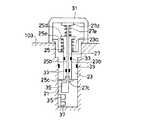
図2は、記録スイッチ11を示す断面図である。図2に示すように記録スイッチ11は、内視鏡スコープ105の操作部103に設けられた所定の深さの挿入孔21に配置され、中央部にばね受け23aを有し、かつ、中心部に貫通孔23bが設けられたガイド23と、ガイド23の貫通孔23bに摺動可能に挿入され、中心部に貫通孔25bが設けられ、一端にストッパー25c、他端に皿部25dを有し、皿部25dとばね受け23aの間に配置されたばね25eにより付勢されたシャフト25と、シャフト25の貫通孔25bに摺動可能に挿入され、一端にストッパー27c、他端に皿部27dを有し、皿部27dと皿部25dの間に配置されたばね27eにより付勢されたシャフト27とを備える。
【0027】
また、ストッパー25cの下側には接点29-1を配置したL字形の接点受け25fが設けられている。さらに挿入孔21の底部には接点29-2が配置されている。なお、皿部27dの上面側にはシャフト27を保護するゴムキャップ31が設けられている。
【0028】
また、挿入孔21とガイド23との境界、ガイド23とシャフト25との境界およびシャフト25とシャフト27との境界にはOリング33が設けられている。
【0029】
また、ばね25eとばね27eの付勢力の関係は、(ばね25eの付勢力)>(ばね27eの付勢力)になっている。
【0030】
このため、ゴムキャップ31を押し込むとばね27eのみ縮み、シャフト27が押し下げられ、接点29-1がONされる。さらにゴムキャップ31を押し込むと、シャフト27によりシャフト27が押し下げられ、接点29-2がONされる。
【0031】
なお、記録スイッチ11としては、図3に示すように挿入孔21の底部の側面にフォトインタラプタ35、37を深さ方向に並べて配置し、さらにシャフト27のフォトインタラプタ35,37側に遮光板39を設けた機構としても良い。なお、図2に示す記録スイッチ11と同一部材には同一符号を付して説明は省略する。この場合、フォトインタラプタ35,37を遮光したか否かでその出力電圧変化をスイッチ信号発生回路119が判定する。
【0032】
また、記録スイッチ11は、図2、図3に示すものに限らず、図4(a)に示すようにレバー41を上下に動かす、または、図4(b)に示すようにレバー43を上下にスライドする形式のものでもよい。いずれの形式でも長さの異なる複数のストロークを識別し、この識別結果に応じて、図示しない複数の接点をそれぞれON/OFFさせることができる。また、押圧により電気抵抗が変化する導電ゴムを用いて記録スイッチ11を構成しても良い。
【0033】
このように第1参考例に示された内視鏡装置10は、2種類の長さの異なるストロークを識別し、該識別結果に応じて二つの接点13a,13bをONさせる画像記録用の記録スイッチ11を内視鏡スコープ105に設け、ONされた接点13に対応した記録装置に画像を記録させるようにしているので、画像を複数の記録装置に記録させる場合でもその操作を簡単に行うことが可能となる。
【0034】
図5(a)は、内視鏡装置の第2参考例を示す要部ブロック図である。なお、第2参考例に示された内視鏡装置50は、図1に示す第1参考例の内視鏡装置10と記録スイッチ51とスイッチ信号発生回路59以外は同一であるので内視鏡スコープ105とスイッチ信号発生回路59のみ示す。
【0035】
第2参考例の内視鏡装置50は、少なくとも2種類の押圧時間を識別し該識別結果に基づいて少なくとも2種類の記録指示信号を発生する入力手段を内視鏡スコープに設けた場合の実施の形態であり、図1に示す内視鏡装置10の記録スイッチ11とスイッチ信号発生回路119に換えて、記録スイッチ51とスイッチ信号発生回路59を設けたことにより実現されている。
【0036】
記録スイッチ51は、図5(a)に示すように接点53が一つの通常の押しボタンスイッチである。
【0037】
また、スイッチ信号発生回路59は、図5(b)に示すように二つのスイッチ信号発生部55a,55bと、判定部57とから成る。スイッチ信号発生部55aは、記録スイッチ51が押され、接点53がONされると、その旨を示す信号を制御回路125に出力する。
【0038】
スイッチ信号発生部55bは、判定部57により記録スイッチ51の接点53が予め設定されている設定時間より長くONされていると判定されたとき、その旨を示す信号を制御回路125に出力する。なお、スイッチ信号発生部55a,55bは、第1参考例のスイッチ信号発生回路119と同様なチャッタリング除去機能を備えてもよい。
【0039】
これにより、制御回路125は、記録スイッチ51の接点53がONされている時間に対応した記録装置に画像を記録させる。
【0040】
このように、第2参考例の内視鏡装置50は、記録スイッチ51の接点53が予め設定されている設定時間より長くONされているか否かを判定する判定部57を設け、記録スイッチ51の接点がONされている時間に応じた記録装置に画像を記録させるようにしているので、画像を複数の記録装置に記録させる場合でもその操作を簡単に行うことが可能となる。
【0041】
図6は、内視鏡装置の第3参考例を示すブロック図である。第3参考例の内視鏡装置は、報知手段としてスピーカ135が追加されている以外は図1の内視鏡装置の構成と同様の構成を有するので、重複する構成要素の説明は省略する。
【0042】
本参考例においては、入力手段である記録スイッチ11によりON/OFF制御される接点13a及び13bに対応する信号をスイッチ信号発生回路119が発生し、これを制御回路125が認識したときに、対応する記録装置に画像を記録させるとともに、応答信号としてスピーカ135を鳴動して術者に報知するものである。また、スピーカ135を鳴動して術者に報知するタイミングは、スイッチ信号を制御回路125が認識したとき以外に、制御回路125から、各記録装置129、131、133に対して画像の記録指示を出力したとき、または各記録装置129、131、133からの画像記録動作の完了信号を制御回路125が受信したときを選んでも良い。
【0043】
このスピーカ135による報知音は、記録指示信号の種類に応じて変更するのが望ましい。例えば、接点13aがONされたときは「ピッ」、接点13bがONされたときは「ピッ、ピッ」というように、音の回数を変えるか、音の高さまたは音の長さを変えてもよい。これにより入力手段からの操作の確認が容易となり、誤操作を防止することができる。
【0044】
なお、本参考例の変形例として、スピーカ135に変えて表示により術者に報知する表示手段を内視鏡本体装置(例えば、キーボード127上、モニタ109の外枠等)や操作部103に設けてもよいし、モニタ109の表示画像に重畳して報知のための表示を行ってもよい。モニタ109に表示する場合には、それぞれの記録装置に対応する表示マークを制御回路125によりメモリ121上に発生させることにより、モニタ109に表示される。
【0045】
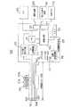
図7は、本発明に係る内視鏡装置の実施の形態を示すブロック図である。本実施の形態に示された内視鏡装置は、第2の画像記録手段に記録すべき画像の識別情報を登録するための登録手段としてメモリB(符号122)を図1の構成に追加したものである。なお、従来のメモリ121は、メモリB122と区別するために、本実施例ではメモリA121と呼ぶがその内容には変化がない。
【0046】
本実施の形態に示された内視鏡装置は、画像の識別情報を登録するための登録手段としてメモリB122が追加されていることと、制御回路125の動作以外は図1に示された内視鏡装置の構成と同様の構成であるので、重複する構成要素の説明は省略する。
【0047】
本実施の形態に係る内視鏡装置においては、入力手段は第1参考例に示された内視鏡装置と同様であり、記録スイッチ11が押されると、そのストロークに応じて接点13aが単独で、あるいは接点13aと接点13bとが共にONとなる。
【0048】
記録スイッチ11が短いストロークで1段押され、接点13aが単独でONした場合、接点13aに対応したスイッチ信号がスイッチ信号発生回路119から出力され、これを受けた制御回路125は、メモリA121に保持された画像をインターフェース123を介して撮影装置129と電子ファイリング装置131に記録させる。
【0049】
記録スイッチ11がさらに長いストロークまで2段押されると、接点13aのON状態に加えて接点13bがONの状態となり、接点13bのON状態に対応するスイッチ信号を制御回路125が受けると、このときの画像の識別情報をメモリB122に記憶させる。この識別情報は、接点13aがONしたときに記録された電子ファイリング装置131における画像番号であってもよいし、画像の電子ファイリング装置131内におけるアドレスであってもよい。
【0050】
こうして内視鏡スコープ105の操作中は、ビデオプリンタ133に記録すべき画像の識別情報だけをメモリB122に登録しておく。そして、内視鏡スコープの操作が終了した後、例えばキーボード127からの指示によって、メモリB122に登録された画像の識別情報を読出し、該当する画像を電子ファイリング装置131から読出して、インターフェース123を介してビデオプリンタ133に記録させる。
【0051】
これにより、ビデオプリンタに出力すべき画像の指示速度がビデオプリンタの出力速度に限定されることや、ビデオプリンタのエラー等による観察中断が無くなり、内視鏡スコープによる観察及び画像収集を短時間で終了させることができる。
【0052】
なお、第1参考例及び第2参考例に示された内視鏡装置10,50の記録スイッチ11,51は、内視鏡スコープ105の操作部103に設けた場合を示したが、操作部103の操作は基本的に左手片手操作であり、中指で送気、送水スイッチ111d、人差し指で吸引スイッチ111eとフリーズスイッチ111cを操作するため、記録スイッチ11,51は親指で操作できる位置にある方が操作性は良くなる。
【0053】
また、第2参考例の内視鏡装置において説明したように、少なくとも2種類の押圧時間を識別し該識別結果に基づいて少なくとも2種類の記録指示信号を発生する入力手段である記録スイッチ51とスイッチ信号発生回路59を第3及び第4の実施の形態に用いることもできる。
【0054】
また、本発明の実施の形態及び参考例においては、一つのスイッチが異なる長さの2つのストロークにより2種類の記録指示信号を発生させる例を示したが、異なる3つ以上のストロークを識別して3種類以上の記録指示信号を発生し、3以上の画像記録装置を制御するように拡張することもできる。
【0055】
さらに、固体撮像素子が先端部にある電子内視鏡に限らず、硬性鏡やファイバースコープの接眼部に固体撮像素子を配置してモニタ上に出画するスコープカメラでも本発明は適用することができる。
【0056】
また、この内視鏡装置においては、入力手段により記録指示信号が発生されたことまたは記録指示信号に従って画像記録手段に画像を記録する動作の開始ないし完了を音声及びまたは表示により術者に報知する報知手段をさらに具備したことにより、操作の確認を行なうことができる。
【0057】
【発明の効果】
本発明に係る内視鏡装置によれば、例えば、第1の画像記録手段として画像ファイリング装置、第2の画像記録手段としてビデオプリンタを用いる場合、内視鏡スコープを操作して観察を行う時には、ビデオプリンタに出力すべき画像の識別情報を登録手段に登録しておき、観察終了後に画像ファイル装置から登録された画像をビデオプリンタに出力することができる。このため、ビデオプリンタに出力すべき画像の指示速度がビデオプリンタの出力速度に限定されることや、ビデオプリンタのエラー等による観察中断が無くなり、内視鏡スコープによる観察及び画像収集を短時間で終了させることができ、被検者の苦痛を軽減し、検査効率を高めることができるという効果がある。
【0058】
また、少なくとも2種類の長さの異なるストロークを識別し該識別結果に基づいて少なくとも2種類の記録指示信号を発生する入力手段を内視鏡スコープに設け、記録指示信号の種類に応じて、画像の記録と画像の識別情報の登録をさせるようにしているので、その操作を簡単に行うことができるという効果がある。
【0059】
さらに、本発明によれば、少なくとも2種類の押圧時間を識別し該識別結果に基づいて少なくとも2種類の記録指示信号を発生する入力手段を内視鏡スコープに設け、記録指示信号の種類に応じて、画像の記録と画像の識別情報の登録をさせるようにしているので、画像を複数の記録装置に記録させる場合でもその操作を簡単に行うことがができるという効果がある。
【図面の簡単な説明】
【図1】内視鏡装置の第1参考例を示すブロック図である。
【図2】 図1に示す内視鏡装置の記録スイッチを示す断面図である。
【図3】 フォトインタラプタを用いた記録スイッチを示す断面図である。
【図4】 図2と図3に示す記録スイッチ以外の記録スイッチを示す平面図である。
【図5】内視鏡装置の第2参考例を示す要部ブロック図である。
【図6】内視鏡装置の第3参考例を示すブロック図である。
【図7】 本発明に係る内視鏡装置の実施の形態を示すブロック図である。
【図8】 従来の内視鏡装置の外観を示す斜視図である。
【図9】 従来の内視鏡装置の構成を示すブロック図である。
【符号の説明】
10,50…内視鏡装置、11,51…記録スイッチ、13,53…接点、21…挿入孔、23…ガイド、23a…ばね受け、23b,25b…貫通孔、25,27…シャフト、25c,27c…ストッパー、25d,27d…皿部、25e,27e…ばね、25f…接点受け、29-1,29-2…接点、31…ゴムキャップ、33…Oリング、35,37…フォトインタラプタ、39…遮光板、41…レバー、55a,55b,59…スイッチ信号発生回路、57…判定部、101…挿入部、103…操作部、105…内視鏡スコープ、107…内視鏡装置本体、109…モニタ、111a,111b…記録スイッチ、113…光源、115…光源制御回路、117…ビデオ処理回路、119…スイッチ信号発生回路、121,122…メモリ、123…インターフェース、125…制御回路、127…キーボード、129…撮影装置、131…電子ファイリング装置、133…ビデオプリンタ、135…スピーカ。[0001]
BACKGROUND OF THE INVENTION
The present invention relates to a medical endoscope apparatus, and more particularly to an endoscope apparatus that can be easily operated when recording an image obtained by an endoscope scope inserted into a body.
[0002]
[Prior art]
In recent years, a plurality of recording apparatuses are connected to a medical endoscope apparatus, and an image obtained by the endoscope apparatus is recorded on a plurality of recording apparatuses depending on applications.
[0003]
FIG. 8 is a perspective view showing an appearance of a conventional endoscope apparatus. As shown in FIG. 8, a
[0004]
FIG. 9 is a block diagram illustrating the function and configuration of the
[0005]
Next, the operation of the
[0006]
The image is also stored in the
[0007]
When the
[0008]
Next, when the
[0009]
As a result, an image is recorded in the recording device (the
[0010]
[Problems to be solved by the invention]
TraditionalIn the endoscope apparatus, when the same still image is recorded in two recording apparatuses, two different switch operations corresponding to the respective recording apparatuses are necessary, and there is a problem that the recording operation is complicated.
[0011]
The present invention has been made in view of the above circumstances, and an object thereof is to provide an endoscope apparatus that can easily perform the operation even when the same still image is recorded in a plurality of recording apparatuses. It is in.
[0012]
[Means for Solving the Problems]
In order to solve the above-described problem, an endoscope apparatus according to the present invention, as described in
[0013]
Also,The invention described in
[0014]
further,The invention of claim 3 of the present application isIn order to solve the above-mentioned problem, claim 1 or 2In the endoscope apparatus ofThe input means is a switch for identifying at least two types of strokes having different lengths and generating at least first and second recording instruction signals according to the identification result..
[0015]
Also,The invention according to claim 4 of the present application isIn order to solve the above-mentioned problem, the
[0016]
Endoscopic device of the present applicationAccording to the present invention, the input means can be, for example, a two-stage push button switch provided in an imaging means such as an endoscope scope, and the stroke for operating one push button (in this case, the depth of push-in) 2), two kinds of recording instruction signals can be generated. The control means selects a recording apparatus to record an image based on the two types of recording instruction signals and records the image. Therefore, even when the same still image is recorded on a plurality of recording devices, the operation can be easily performed with one push button switch.
[0017]
Further, the input means can be a combination of a simple push button switch and a switch signal generation circuit for determining a time when the switch is pressed. The switch signal generation circuit is provided in the endoscope scope. It is possible to determine the time during which the push button switch is ON, and generate two types of recording instruction signals depending on the length of this time. The control means selects a recording apparatus to record an image based on the two types of recording instruction signals and records the image. Therefore, even when the same still image is recorded on a plurality of recording devices, the operation can be easily performed with one push button switch.
[0018]
Further, the control means that has received the recording instruction signal generated by the input means notifies the operator by voice or display that the recording instruction signal has been received or that the operation based on the recording instruction signal has been started or completed. Notification can be made, and the surgeon can easily confirm the operation of the input means.
[0019]
Further, among the plurality of recording devices, the first recording device is a recording device capable of recording and reading, and all images recorded on the second recording device are also recorded on the first recording device. The identification information of the image to be recorded in the second image recording means is registered in the registration means in accordance with the second recording instruction signal, and after the observation by the endoscope scope is completed, the identification information registered in the registration means is added to the identification information registered in the registration means. Corresponding images can be read from the first image recording means and recorded on the second image recording means.
[0020]
DETAILED DESCRIPTION OF THE INVENTION
Embodiments of an endoscope apparatus according to the present invention will be described with reference to the accompanying drawings.This will be described in detail.
[0021]
FIG. 1 shows a first reference example of an endoscope apparatus.FIG. In addition,First reference exampleSince the external configuration of the
[0022]
As shown in FIG.First reference
[0023]
Shown in FIG.The input means is realized as a
[0024]
The switch
[0025]
When the
[0026]
FIG. 2 is a cross-sectional view showing the
[0027]
Further, an L-shaped
[0028]
An O-
[0029]
The relationship between the urging forces of the
[0030]
Therefore, when the
[0031]
As shown in FIG. 3, the
[0032]
The
[0033]
in this wayShown in the first reference
[0034]
FIG. 5 (a)Second reference example of an endoscopic deviceIt is a principal part block diagram which shows. In addition,Shown in the second reference
[0035]
Second reference
[0036]
The
[0037]
The switch
[0038]
When it is determined by the
[0039]
As a result, the
[0040]
in this way,Second reference
[0041]
FIG. 6 shows a third reference example of the endoscope apparatus.FIG.Endoscopic device of the third reference example1 except that a
[0042]
Reference example, The switch
[0043]
The notification sound from the
[0044]
In addition,Reference exampleAs a modification of the above, display means for notifying the surgeon by display instead of the
[0045]
FIG. 7 relates to the present invention.Embodiment of endoscope apparatusFIG.The endoscope apparatus shown in the present embodiment isA memory B (reference numeral 122) is added to the configuration of FIG. 1 as registration means for registering identification information of an image to be recorded in the second image recording means. The
[0046]
The endoscope apparatus shown in the present embodiment isExcept for the addition of the memory B122 as registration means for registering the image identification information and the operation of the control circuit 125.Of the endoscope apparatus shown in FIG.Since the configuration is the same as the configuration, description of the overlapping components is omitted.
[0047]
In the endoscope apparatus according to the present embodiment,Input meansEndoscopic device shown in the first reference exampleWhen the
[0048]
When the
[0049]
When the
[0050]
Thus, only the identification information of the image to be recorded on the
[0051]
As a result, the instruction speed of the image to be output to the video printer is limited to the output speed of the video printer, and there is no interruption of observation due to an error of the video printer, and observation and image collection by the endoscope scope can be performed in a short time. Can be terminated.
[0052]
In addition,Shown in the first reference example and the second reference exampleAlthough the recording switches 11 and 51 of the
[0053]
Also,In the endoscope apparatus of the second reference exampleAs described above, the
[0054]
Also,In the embodiments and reference examples of the present invention,Although an example in which one switch generates two types of recording instruction signals by two strokes having different lengths has been shown, three or more types of recording instruction signals are generated by identifying three or more different strokes. The image recording apparatus can be extended to control.
[0055]
Furthermore, the present invention is applicable not only to an electronic endoscope having a solid-state image pickup device at the tip, but also to a scope camera in which a solid-state image pickup device is placed on the eyepiece of a rigid mirror or fiberscope and displayed on a monitor. Can do.
[0056]
Further, in this endoscope apparatus, the operator is notified by voice and / or display that the recording instruction signal is generated by the input means or the start or completion of the operation of recording an image on the image recording means in accordance with the recording instruction signal. By further providing the notification means, the operation can be confirmed.
[0057]
【The invention's effect】
According to the endoscope apparatus according to the present invention, for example, when an image filing device is used as the first image recording unit and a video printer is used as the second image recording unit, the endoscope scope is operated for observation. Should output to a video printerThe image identification informationIt is possible to output the registered image from the image file device to the video printer after registration in the registration means. For this reason, the instruction speed of the image to be output to the video printer is limited to the output speed of the video printer, and the observation interruption due to the error of the video printer is eliminated. It is possible to end the test, and it is possible to reduce the pain of the subject and increase the examination efficiency.
[0058]
Also, an input means for identifying at least two types of strokes having different lengths and generating at least two types of recording instruction signals based on the identification result is provided in the endoscope scope, and an image is displayed in accordance with the type of recording instruction signal. Recording and registration of image identification information is performed, so that the operation can be easily performed.
[0059]
Furthermore, according to the present invention, an input means for identifying at least two types of pressing times and generating at least two types of recording instruction signals based on the identification results is provided in the endoscope scope, and according to the types of recording instruction signals. Thus, since the image is recorded and the identification information of the image is registered, there is an effect that the operation can be easily performed even when the image is recorded in a plurality of recording devices.
[Brief description of the drawings]
[Figure 1]First reference example of an endoscopic deviceFIG.
FIG. 2 is a cross-sectional view showing a recording switch of the endoscope apparatus shown in FIG.
FIG. 3 is a cross-sectional view showing a recording switch using a photo interrupter.
4 is a plan view showing a recording switch other than the recording switches shown in FIGS. 2 and 3. FIG.
[Figure 5]Second reference example of an endoscopic deviceIt is a principal part block diagram which shows.
[Fig. 6]Third reference example of an endoscopic deviceFIG.
FIG. 7 relates to the present invention.Embodiment of endoscope apparatusFIG.
FIG. 8 is a perspective view showing an appearance of a conventional endoscope apparatus.
FIG. 9 is a block diagram showing a configuration of a conventional endoscope apparatus.
[Explanation of symbols]
DESCRIPTION OF
Claims (4)
Translated fromJapaneseこの撮像手段により撮像された画像を記録する少なくとも第1及び第2の画像記録手段と、
少なくとも第1及び第2の画像記録用の記録指示信号を発生する入力手段と、
前記第1又は第2の記録指示信号に従って、前記第1の画像記録手段に前記画像を記録する第1の記録制御手段と、
前記第2の記録指示信号に従って前記第2の画像記録手段に記録すべき画像の識別情報を登録する登録手段と、
を備えることを特徴とする内視鏡装置。An imaging means for imaging an image of the body cavity of the subject;
At least first and second image recording means for recording images picked up by the image pickup means;
Input means for generating recording instruction signals forat least first and second image recording;
First recording control means for recording the image on the first image recording means in accordance withthe first or second recording instruction signal;
Registration means for registering identification information of an image to be recorded in the second image recording means in accordance withthe second recording instruction signal;
An endoscope apparatus comprising:
を備えることを特徴とする請求項1に記載の内視鏡装置。Second recording control means for reading an image corresponding to the identification information of the image registered in the registration means from the first image recording means and recording the image on the second image recording means;
The endoscope apparatus according to claim 1, further comprising:
Priority Applications (1)
| Application Number | Priority Date | Filing Date | Title |
|---|---|---|---|
| JP33940595AJP3817287B2 (en) | 1995-01-10 | 1995-12-26 | Endoscope device |
Applications Claiming Priority (3)
| Application Number | Priority Date | Filing Date | Title |
|---|---|---|---|
| JP7-1649 | 1995-01-10 | ||
| JP164995 | 1995-01-10 | ||
| JP33940595AJP3817287B2 (en) | 1995-01-10 | 1995-12-26 | Endoscope device |
Publications (2)
| Publication Number | Publication Date |
|---|---|
| JPH08243079A JPH08243079A (en) | 1996-09-24 |
| JP3817287B2true JP3817287B2 (en) | 2006-09-06 |
Family
ID=26334918
Family Applications (1)
| Application Number | Title | Priority Date | Filing Date |
|---|---|---|---|
| JP33940595AExpired - LifetimeJP3817287B2 (en) | 1995-01-10 | 1995-12-26 | Endoscope device |
Country Status (1)
| Country | Link |
|---|---|
| JP (1) | JP3817287B2 (en) |
Families Citing this family (3)
| Publication number | Priority date | Publication date | Assignee | Title |
|---|---|---|---|---|
| EP1119193A3 (en) | 2000-01-19 | 2010-11-24 | Sony Corporation | Data processing device for a video camera-recorder with integrated printer, and method for operating the printer |
| JP2006167139A (en)* | 2004-12-15 | 2006-06-29 | Pentax Corp | Electronic endoscope system and electronic endoscope |
| JP4731250B2 (en)* | 2005-08-30 | 2011-07-20 | Hoya株式会社 | Electronic endoscope device |
- 1995
- 1995-12-26JPJP33940595Apatent/JP3817287B2/ennot_activeExpired - Lifetime
Also Published As
| Publication number | Publication date |
|---|---|
| JPH08243079A (en) | 1996-09-24 |
Similar Documents
| Publication | Publication Date | Title |
|---|---|---|
| JP3631257B2 (en) | Electronic endoscope device | |
| JP3730672B2 (en) | Electronic endoscope device | |
| JP3887453B2 (en) | Endoscope device | |
| JP3482238B2 (en) | Endoscope imaging device | |
| JP2004166761A (en) | Vibrating object observing system and vocal cord observing processing apparatus | |
| WO2006085415A1 (en) | Endoscope device | |
| JP3817287B2 (en) | Endoscope device | |
| JP2005181365A (en) | Imaging apparatus | |
| JP4408456B2 (en) | Information processing device | |
| JP6594727B2 (en) | Endoscope | |
| JP2002290783A (en) | Electronic endoscope device | |
| JP3506968B2 (en) | Endoscope device | |
| US20030063208A1 (en) | Image pick-up apparatus | |
| JP4578608B2 (en) | Endoscope system | |
| US7525594B2 (en) | Camera having mode-selecting power-controlling buttons | |
| JPH09331472A (en) | Display controller | |
| US20030112348A1 (en) | Electronic image capture device with frame-and video-specific capture buttons | |
| JP2010050953A (en) | Imaging device, reproduction device and image reproduction program | |
| JP2000023901A (en) | Endoscope | |
| JP4648576B2 (en) | Electronic endoscope device | |
| JP2003325444A (en) | Electronic endoscope device and video signal processing device | |
| JP4423681B2 (en) | Information processing apparatus and recording medium | |
| JP4813178B2 (en) | Endoscope device | |
| US20010030684A1 (en) | Electronic endoscope | |
| JP3831566B2 (en) | Electronic endoscope device |
Legal Events
| Date | Code | Title | Description |
|---|---|---|---|
| A131 | Notification of reasons for refusal | Free format text:JAPANESE INTERMEDIATE CODE: A131 Effective date:20040106 | |
| A521 | Written amendment | Free format text:JAPANESE INTERMEDIATE CODE: A523 Effective date:20040308 | |
| A131 | Notification of reasons for refusal | Free format text:JAPANESE INTERMEDIATE CODE: A131 Effective date:20051004 | |
| A521 | Written amendment | Free format text:JAPANESE INTERMEDIATE CODE: A523 Effective date:20051205 | |
| TRDD | Decision of grant or rejection written | ||
| A01 | Written decision to grant a patent or to grant a registration (utility model) | Free format text:JAPANESE INTERMEDIATE CODE: A01 Effective date:20060606 | |
| A61 | First payment of annual fees (during grant procedure) | Free format text:JAPANESE INTERMEDIATE CODE: A61 Effective date:20060612 | |
| FPAY | Renewal fee payment (event date is renewal date of database) | Free format text:PAYMENT UNTIL: 20100616 Year of fee payment:4 | |
| FPAY | Renewal fee payment (event date is renewal date of database) | Free format text:PAYMENT UNTIL: 20100616 Year of fee payment:4 | |
| FPAY | Renewal fee payment (event date is renewal date of database) | Free format text:PAYMENT UNTIL: 20110616 Year of fee payment:5 | |
| FPAY | Renewal fee payment (event date is renewal date of database) | Free format text:PAYMENT UNTIL: 20120616 Year of fee payment:6 | |
| FPAY | Renewal fee payment (event date is renewal date of database) | Free format text:PAYMENT UNTIL: 20130616 Year of fee payment:7 | |
| EXPY | Cancellation because of completion of term |