JP3815448B2 - Information collection device and pulse meter - Google Patents
Information collection device and pulse meterDownload PDFInfo
- Publication number
- JP3815448B2 JP3815448B2JP2003075838AJP2003075838AJP3815448B2JP 3815448 B2JP3815448 B2JP 3815448B2JP 2003075838 AJP2003075838 AJP 2003075838AJP 2003075838 AJP2003075838 AJP 2003075838AJP 3815448 B2JP3815448 B2JP 3815448B2
- Authority
- JP
- Japan
- Prior art keywords
- body motion
- pulse wave
- pulse
- motion detection
- sensor
- Prior art date
- Legal status (The legal status is an assumption and is not a legal conclusion. Google has not performed a legal analysis and makes no representation as to the accuracy of the status listed.)
- Expired - Fee Related
Links
- 230000033001locomotionEffects0.000claimsdescription214
- 238000001514detection methodMethods0.000claimsdescription184
- 238000004458analytical methodMethods0.000claimsdescription52
- 210000000707wristAnatomy0.000claimsdescription24
- 230000001133accelerationEffects0.000claimsdescription11
- 238000012545processingMethods0.000claimsdescription10
- 230000008859changeEffects0.000claimsdescription8
- 238000000034methodMethods0.000claimsdescription5
- 230000008569processEffects0.000claimsdescription5
- 238000006073displacement reactionMethods0.000claimsdescription4
- 230000003044adaptive effectEffects0.000description34
- 238000010586diagramMethods0.000description33
- 238000010248power generationMethods0.000description24
- 238000006243chemical reactionMethods0.000description18
- 230000005540biological transmissionEffects0.000description17
- 230000004048modificationEffects0.000description17
- 238000012986modificationMethods0.000description17
- 230000003321amplificationEffects0.000description16
- 238000003199nucleic acid amplification methodMethods0.000description16
- 239000000758substrateSubstances0.000description16
- 230000015572biosynthetic processEffects0.000description12
- 238000003786synthesis reactionMethods0.000description12
- 239000003990capacitorSubstances0.000description11
- 230000006870functionEffects0.000description10
- 238000009532heart rate measurementMethods0.000description8
- 230000007246mechanismEffects0.000description6
- 230000004907fluxEffects0.000description3
- 238000001228spectrumMethods0.000description3
- 230000002194synthesizing effectEffects0.000description3
- 239000008280bloodSubstances0.000description2
- 210000004369bloodAnatomy0.000description2
- 210000004204blood vesselAnatomy0.000description2
- 238000004891communicationMethods0.000description2
- 239000006059cover glassSubstances0.000description2
- 230000000694effectsEffects0.000description2
- 239000000284extractSubstances0.000description2
- 230000003247decreasing effectEffects0.000description1
- 230000005484gravityEffects0.000description1
- 239000004973liquid crystal related substanceSubstances0.000description1
- 239000000463materialSubstances0.000description1
- 239000000203mixtureSubstances0.000description1
- 230000003287optical effectEffects0.000description1
- 230000035699permeabilityEffects0.000description1
- 238000005070samplingMethods0.000description1
- 230000009466transformationEffects0.000description1
- 238000004804windingMethods0.000description1
Images


Classifications
- A—HUMAN NECESSITIES
- A61—MEDICAL OR VETERINARY SCIENCE; HYGIENE
- A61B—DIAGNOSIS; SURGERY; IDENTIFICATION
- A61B5/00—Measuring for diagnostic purposes; Identification of persons
- A61B5/68—Arrangements of detecting, measuring or recording means, e.g. sensors, in relation to patient
- A61B5/6801—Arrangements of detecting, measuring or recording means, e.g. sensors, in relation to patient specially adapted to be attached to or worn on the body surface
- A61B5/6802—Sensor mounted on worn items
- A61B5/681—Wristwatch-type devices
- A—HUMAN NECESSITIES
- A61—MEDICAL OR VETERINARY SCIENCE; HYGIENE
- A61B—DIAGNOSIS; SURGERY; IDENTIFICATION
- A61B5/00—Measuring for diagnostic purposes; Identification of persons
- A61B5/02—Detecting, measuring or recording for evaluating the cardiovascular system, e.g. pulse, heart rate, blood pressure or blood flow
- A61B5/024—Measuring pulse rate or heart rate
- A61B5/02416—Measuring pulse rate or heart rate using photoplethysmograph signals, e.g. generated by infrared radiation
- A—HUMAN NECESSITIES
- A61—MEDICAL OR VETERINARY SCIENCE; HYGIENE
- A61B—DIAGNOSIS; SURGERY; IDENTIFICATION
- A61B5/00—Measuring for diagnostic purposes; Identification of persons
- A61B5/72—Signal processing specially adapted for physiological signals or for diagnostic purposes
- A61B5/7203—Signal processing specially adapted for physiological signals or for diagnostic purposes for noise prevention, reduction or removal
- A61B5/7207—Signal processing specially adapted for physiological signals or for diagnostic purposes for noise prevention, reduction or removal of noise induced by motion artifacts
- A61B5/721—Signal processing specially adapted for physiological signals or for diagnostic purposes for noise prevention, reduction or removal of noise induced by motion artifacts using a separate sensor to detect motion or using motion information derived from signals other than the physiological signal to be measured
Landscapes
- Health & Medical Sciences (AREA)
- Life Sciences & Earth Sciences (AREA)
- Engineering & Computer Science (AREA)
- Surgery (AREA)
- Animal Behavior & Ethology (AREA)
- Veterinary Medicine (AREA)
- Public Health (AREA)
- Physics & Mathematics (AREA)
- General Health & Medical Sciences (AREA)
- Biophysics (AREA)
- Pathology (AREA)
- Biomedical Technology (AREA)
- Heart & Thoracic Surgery (AREA)
- Medical Informatics (AREA)
- Molecular Biology (AREA)
- Signal Processing (AREA)
- Physiology (AREA)
- Cardiology (AREA)
- Computer Vision & Pattern Recognition (AREA)
- Artificial Intelligence (AREA)
- Psychiatry (AREA)
- Measuring Pulse, Heart Rate, Blood Pressure Or Blood Flow (AREA)
- Measurement Of The Respiration, Hearing Ability, Form, And Blood Characteristics Of Living Organisms (AREA)
Description
Translated fromJapanese【0001】
【発明が属する技術分野】
本発明は、情報収集装置および脈拍計に係り、特に人体の一部に装着して歩行中あるいは走行中の脈拍を測定するために用いられる情報収集装置および脈拍計に関する。
【従来の技術】
従来より、人体の一部に装着して歩行中あるいは走行中の脈拍を測定する脈波計が知られている。
例えば、特許文献1には、腕時計型の脈拍計が開示されている。
上記特許文献1に開示されている脈拍計は、加速度センサにより検出した体動信号の周波数分析結果に基づいて体動信号の高調波成分のすべてに相当する周波数成分を脈波信号の周波数分析結果から除去し、体動信号の高調波成分が除去された脈波信号の周波数分析結果のなかから最大のパワーを有する周波数成分を抽出し、当該抽出した周波数成分に基づいて脈拍数を算出するという構成を採っていた。
【0002】
【特許文献1】
特許第2816944号公報
【0003】
【発明が解決しようとする課題】
上記従来の脈拍計においては、体動成分の検出を加速度センサにより行っていたため、加速度が小さい動作については脈波信号への影響が大きい場合でも検出できず、正しい脈波成分を抽出することができないという不具合があった。
腕時計型の脈拍形においてこのような加速度が小さい動作としては、手を握ったり開いたりする動作がある。手を握ったり開いたりする動作を行うと、手首の直径は数ミリオーダーで変化することとなる。
この影響は、脈波成分には大きく現れるが、体動成分には現れない。このため、脈波成分を正確に抽出することができず、正しい脈拍を計測することができない場合が生じるという問題点があった。
そこで、本発明の目的は、加速度が小さい体動成分が発生した場合でも、確実に脈波成分から体動成分を確実に除去して正確に脈拍数算出を行うための情報収集装置および脈拍計を提供することにある。
【0005】
【課題を解決するための手段】
上記課題を解決するため、人体に装着して脈拍に関する情報を収集する情報収集装置において、装着部位の生体表面の形状変化に伴って発生する体動成分を検出し第1体動検出信号を出力する第1体動検出部と、前記人体の動きに伴って発生する体動成分を検出し第2体動検出信号を出力する第2体動検出部と、脈波成分を検出し脈波検出信号を出力する脈波検出部と、を備え、前記人体の動きが検出される場合には、前記第2体動検出信号に基づいて前記脈波検出信号から体動成分を除去し、前記人体の動きが検出されない場合には、前記第1体動検出信号に基づいて前記脈波検出信号から体動成分を除去する、ことを特徴としている。
上記構成によれば、第1体動検出部は、装着部位の生体表面の形状変化に伴って発生する体動成分を検出し第1体動検出信号を出力する。
第2体動検出部、前記人体の動きに伴って発生する体動成分を検出し第2体動検出信号を出力する。
脈波検出部は、脈波成分を検出し脈波検出信号を出力する。
そして、情報収集装置は、前記人体の動きが検出される場合には、前記第2体動検出信号に基づいて前記脈波検出信号から体動成分を除去し、前記人体の動きが検出されない場合には、前記第1体動検出信号に基づいて前記脈波検出信号から体動成分を除去する。
【0006】
これらの場合において、前記生体表面は、手首の表面であるようにしてもよい。
また、前記第1体動検出部は、圧力センサ、荷重センサあるいは変位センサのいずれかを備えるようにしてもよい。
さらに、前記第2体動検出部は、加速度センサを備えるようにしてもよい。
さらにまた、前記脈波検出部は、脈波センサを備え、前記脈波センサの近傍に前記体動検出部の検出位置を配置するようにしてもよい。
また、前記脈波検出部は、脈波センサを備え、前記脈波センサに対し、装着部位の背面側あるいは同一面側であって前記脈波センサの検出位置を通る同一軸上近傍に前記第1体動検出部および前記第2体動検出部の検出位置を配置するようにしてもよい。
【0007】
また、脈拍計は、上述した情報収集装置から収集した情報を受信する受信部と、受信した情報に含まれる前記第1体動検出信号、前記第2体動検出信号および脈波検出信号に基づいて脈拍数を算出する脈拍数算出部と、を備えたことを特徴としている。
上記構成によれば、受信部は、上述した情報収集装置から収集した情報を受信する。
これにより、脈拍数算出部は、受信した情報に含まれる前記第1体動検出信号、前記第2体動検出信号および脈波検出信号に基づいて脈拍数を算出する。
【0008】
この場合において、収集した情報を外部に送信する送信部を備えるようにしてもよい。
また、前記脈拍数算出部は、前記体動検出信号を周波数分析し第1周波数分析データを生成する第1周波数分析部と、前記脈波検出信号を周波数分析し、第2周波数分析データを生成する第2周波数分析部と、前記第2周波数分析データに対する前記第1周波数分析データの減算処理を行う除去処理部を備えるようにしてもよい。
【0012】
【発明の実施の形態】
次に本発明の好適な実施の形態について図面を参照して説明する。
[1]第1実施形態
図1は、第1実施形態の脈拍測定システムの概要構成図である。
脈拍測定システム10は、大別すると、ユーザの腕に装着されるセンサモジュール11と、PDA(Personal Digital Assistant )、携帯電話などとして構成されるとともに、センサモジュール11と無線を介して接続される携帯装置12と、を備えている。
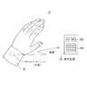
図2はセンサモジュールの装着状態説明図である。
センサモジュール11は、サポータ15により手首に密着するように装着される。サポータ15は、伸縮性を有し、手首を挿入することにより、手首にフィットしてセンサモジュール11を手首の手の甲側に密着させる(図1参照)。
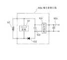
図3は、センサモジュールおよび携帯装置の概要構成ブロック図である。
センサモジュール11は、大別すると、脈波センサ21と、脈波信号増幅回路22と、体動センサ23と、体動信号増幅回路24と、A/D変換回路27と、無線送信回路28と、を備えている。
【0013】
脈波センサ21は、LED(Light Emitting Diode)およびPD(Photo Detector)を備えており、血管内を流れる血液の心拍による脈流に対応する脈波検出信号を脈波信号増幅回路22に出力する。
脈波信号増幅回路22は、入力された脈波検出信号を所定の増幅率で増幅して増幅脈波信号としてA/D変換回路27に出力する。
体動センサ23は、センサモジュール11の装着部位の形状変化、具体的には、手を握ったり開いたりすることによる手首径の変化を検出するためのセンサであり、体動検出信号を体動信号増幅回路24に出力する。この場合において、体動センサは、荷重センサ、圧力センサあるいは変位センサなどで構成することが可能であるが、以下の説明においては、荷重センサを用いる場合を例とする。
【0014】
体動信号増幅回路24は、入力された体動検出信号を所定の増幅率で増幅して増幅体動信号としてA/D変換回路27に出力する。
A/D変換回路27は、入力された増幅脈波信号をアナログ/ディジタル変換して脈波検出データとして無線送信回路28に出力する。またA/D変換回路27は、入力された増幅体動信号をアナログ/ディジタル変換して体動検出データとして無線送信回路28に出力する。
無線送信回路28は、入力された脈波検出データおよび体動検出データに基づいて搬送波を変調し、携帯装置12側に送信する。
【0015】
ここで、センサモジュール11の機械的構成について説明する。
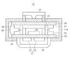
図4は、センサモジュール11の概略断面図である。
センサモジュール11は、図4中、下側をユーザの腕に密着させるようになっている。このため、センサモジュール11のケーシング11Aの下側には、カバーガラス30に保護された状態で脈波センサ21を構成するLED31およびPD32が第1基板33に載置されている。そして第1基板33は、ケーシング11Aに支持されている。第1基板33の上部側には、無線送信回路28および各種回路素子34、35、電池支え36、37が載置されている。
第1基板33には、フレキシブル配線板38を介して第2基板39が接続されている。この第2基板39は、ケーシング11Aに支持されている。
第2基板39の下部側には、各種回路素子40、41が載置されている。
さらに電池支え36、37に支持されて電源42が当接されている。
また、ケーシング11Aの上部側には、体動センサ23が支持されており、この体動センサ23は、電気的に第2基板39に接続されている。
【0016】
次に携帯装置12の構成について説明する。
一方、携帯装置12は、図3に示すように、大別すると、無線受信回路51と、MPU52と、RAM53と、ROM54と、表示装置55と、操作部56と、を備えている。
無線受信回路51は、センサモジュール11の無線送信回路28から送信された脈波検出データおよび体動検出データを受信し、MPU52に出力する。
MPU52は、携帯装置12を制御する。
RAM53は、各種データを一時的に格納する。
ROM54は、MPU52の用いる各種制御プログラムなどをあらかじめ記憶している。
表示装置55は、液晶ディスプレイなどを備え、MPU52の制御下で脈拍数データなどの各種データを表示する。
操作部56は、操作ボタンなどの操作子を備え、データの入力やコマンドの入力などを行う。
【0017】
次に脈波検出データおよび体動検出データを受信したMPUにおける脈拍数算出処理について説明する。
図5は、MPU52が受信した脈波検出データの周波数分析結果の説明図である。
また、図6はMPU52が受信した体動検出データの周波数分析結果の説明図である。
まず、MPU52は、無線受信回路51を介して脈波検出データおよび体動検出データを受信すると、順次RAM53に格納する。
続いてMPU52は、RAM53に所定数のデータが格納されると、RAM53に格納した脈波検出データおよび体動検出データをそれぞれ順次読み出し、FFTを施して周波数分析を行う。
【0018】
図7は、周波数分析後の脈波検出データと周波数分析後の体動検出データとの差である差データの説明図である。
MPU52は、周波数分析後の脈波検出データと周波数分析後の体動検出データとを比較し、同一の周波数成分の差を求めて差データを生成する。
図8は、差データの周波数分析結果の説明図である。
これにより、得られた差データとしての周波数分析結果は、実質的に脈波センサの出力信号(脈波成分+体動成分)から、例えば、手を握ったり開いたりする動作による手首の変形(手首の径の増減)に起因する体動成分を除去したもの、すなわち、主として脈波成分に対応する脈波データとなる。
さらにMPU52は、得られた脈波データから最大の周波数成分を脈拍スペクトルとして、その周波数から脈拍数を算出する。
そしてMPU52は、表示装置55に脈拍数を表示することとなる。
以上の説明のように、本第1実施形態によれば、手を握ったり開いたりする動作による手首の変形(手首の径の増減)に代表される装着部位の変形に起因して発生する体動成分を確実に検出して把握できる。このため、装着部位の変形に起因する体動成分を確実に除去でき、正確な脈波成分検出、ひいては、正確な脈拍数の測定が行える。
【0019】
[1.1]第1変形例
以上の説明においては、脈波検出データから体動検出データを周波数分析(FFT)を行う前に差し引いて差データを算出する構成としていたが、本第1変形例は、脈波検出データおよび体動検出データを周波数分析を行ってから、差データを算出する場合の変形例である。以下、第1変形例について説明する。
本第1変形例においては、MPU52は、RAM53に格納した脈波検出データおよび体動検出データのそれぞれについて周波数分析(FFT)を行う。
次にMPU52は、周波数分析後の脈波検出データと周波数分析後の体動検出データとの差である差データを求める。
そして得られた差データから脈波の高調波成分を抽出し、その周波数から脈拍数を算出することとなる。
【0020】
次により具体的な脈拍数算出処理について説明する。
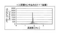
図9は、脈波検出データの周波数分析結果の説明図である。
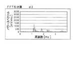
また、図10は体動検出データの周波数分析結果の説明図である。
まず、MPU52は、RAM53に格納した脈波検出データおよび体動検出データをそれぞれ順次読み出し、FFTを施して周波数分析を行う。
図11は、周波数分析後の脈波検出データと周波数分析後の体動検出データとの差である差データの説明図である。
次にMPU52は、周波数分析後の脈波検出データと周波数分析後の体動検出データとを比較し、同一の周波数成分の差を求めて差データを生成する。
【0021】
これにより、得られた差データとしての周波数分析結果は、実質的に脈波センサの出力信号(脈波成分+体動成分)から、例えば、手を握ったり開いたりする動作による手首の変形(手首の径の増減)に起因する体動成分を除去したもの、すなわち、主として脈波成分に対応する脈波データとなる。
さらにMPU52は、得られた脈波データから最大の周波数成分を脈拍スペクトルとして、その周波数から脈拍数を算出する。
そしてMPU52は、表示装置55に脈拍数を表示することとなる。
以上の説明のように、本第1変形例によっても、手を握ったり開いたりする動作による手首の変形(手首の径の増減)に代表される装着部位の変形に起因して発生する体動成分を確実に検出して把握できる。このため、体動成分を確実に除去でき、正確な脈波成分検出、ひいては、正確な脈拍数の測定が行える。
【0022】
[1.2]第2変形例
以上の説明においては、MPUの内部処理として脈波検出データから体動検出データを周波数分析(FFT)を行う前あるいは行った後に差し引いて差データを算出する構成としていたが、本第2変形例は、適応フィルタを用いて脈波検出データから体動成分を除去する場合の変形例である。
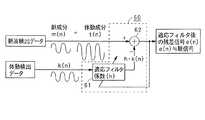
図12に適応フィルタの一例の概要構成ブロック図を示す。
適応フィルタ60は、大別するとフィルタ係数生成部61と、合成部62と、を備えている。
フィルタ係数生成部61は、体動成分除去部として機能しており、合成部62が前回出力したフィルタ適用後のデータに基づいて適応フィルタ係数hを生成する。そして入力された体動成分検出信号として機能する体動検出データ(=k(n))に適応フィルタ係数hを適用して体動除去データ(=h・k(n))を生成して合成部62に出力する。
【0023】
合成部62は、除去処理部として機能しており、前回抽出した脈波検出データ(=脈波成分+体動成分)と体動除去データを合成し、今回の脈波検出データに含まれる体動成分を実質的に除去(減算)して、脈波成分を抽出する。
次に本第2変形例におけるより具体的な脈拍数算出処理について説明する。
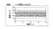
図13は、脈波検出データの一例を時系列順に並べてグラフ化したものである。
また、図14は図13の脈波検出データに対応する体動検出データを同一の時間軸で時系列順に並べてグラフ化したものである。
まず、MPU52は、RAM53に格納した脈波検出データおよび体動検出データを順次読み出し、あるサンプリングタイミングにおける脈波検出データを合成部62に出力する。
【0024】
また、MPU52は、各脈波検出データに対応する圧力検出データをフィルタ係数生成部61に出力する。
これによりフィルタ係数生成部31は、合成部62が前回出力したフィルタ適用後のデータに基づいて適応フィルタ係数hを生成する。そして入力された体動成分検出信号として機能する圧力検出データ(=k(n))に適応フィルタ係数hを適用して体動除去データ(=h・k(n))を合成部62に出力する。
これにより合成部62は、今回の脈波データと体動除去データとを合成して、今回の脈波検出データに含まれる体動成分を実質的に除去(減算)して、脈波成分を抽出して差データ(=フィルタ適用後のデータ)を出力する。
【0025】
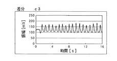
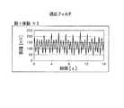
図15は、図13の脈波検出データおよび図14の体動検出データに対して適応フィルタを適用して得られた差データを時系列順に並べてグラフ化したものである。
次にMPU52は、差データに対しFFTを施す。
図16は、図15の差データにFFTを施して得られた周波数分析結果である。
これにより、得られた周波数分析結果は、実質的に脈波センサの出力信号(脈波成分+体動成分)から、手を握ったり開いたりする動作による手首の変形(手首の径の増減)に代表される装着部位の変形に起因して発生する体動成分を除去したもの、すなわち、主として脈波成分に対応する脈波データとなる。
さらにMPU52は、主として脈波成分を含む、得られた脈波データから最大の周波数成分を脈拍スペクトルとして、その周波数から脈拍数を算出する。
そしてMPU52は、表示装置55に脈拍数を表示することとなる。
以上の説明のように、本第2変形例によっても、手を握ったり開いたりする動作による手首の変形(手首の径の増減)に代表される装着部位の変形に起因して発生する体動成分を確実に検出して把握できる。このため、体動成分を確実に除去でき、正確な脈波成分検出、ひいては、正確な脈拍数の測定が行える。
【0026】
[2]第2実施形態
図17は、第2実施形態のセンサモジュールおよび携帯装置の概要構成ブロック図である。図17において、図3の第1実施形態と同様の部分には同一の符号を付している。
センサモジュール11は、大別すると、脈波センサ21と、脈波信号増幅回路22と、第1体動センサ23と、第1体動信号増幅回路24と、第2体動センサ25と、第2体動信号増幅回路26と、A/D変換回路27と、無線送信回路28と、を備えている。
脈波センサ21は、LED(Light Emitting Diode)およびPD(Photo Detector)を備えており、血管内を流れる血液の心拍による脈流に対応する脈波検出信号を脈波信号増幅回路22に出力する。
【0027】
脈波信号増幅回路22は、入力された脈波検出信号を所定の増幅率で増幅して増幅脈波信号としてA/D変換回路27に出力する。
第1体動センサ23は、センサモジュール11の装着部位の形状変化、具体的には、手を握ったり開いたりすることによる手首径の変化を検出するためのセンサであり、第1体動検出信号を第1体動信号増幅回路24に出力する。この場合において、第1体動センサは、荷重センサ、圧力センサあるいは変位センサなどで構成することが可能であるが、以下の説明においては、荷重センサを用いる場合を例とする。
第1体動信号増幅回路24は、入力された第1体動検出信号を所定の増幅率で増幅して第1増幅体動信号としてA/D変換回路27に出力する。
第2体動センサ25は、ユーザの腕振りなどの腕の動きに伴って発生する体動成分を検出するためのセンサであり、第2体動検出信号を第2体動信号増幅回路26に出力する。
【0028】
第2体動信号増幅回路26は、入力された第2体動検出信号を所定の増幅率で増幅して第2体動信号としてA/D変換回路27に出力する。
A/D変換回路27は、入力された増幅脈波信号をアナログ/ディジタル変換して脈波検出データとして無線送信回路28に出力する。またA/D変換回路27は、増幅された第1体動信号をアナログ/ディジタル変換して第1体動検出データとして無線送信回路28に出力する。さらにA/D変換回路27は、増幅された第2体動信号をアナログ/ディジタル変換して第2体動検出データとして無線送信回路28に出力する。
【0029】
無線送信回路28は、入力された脈波検出データ、第1体動検出データあるいは第2体動検出データに基づいて搬送波を変調し、携帯装置12側に送信する。
図18は、センサモジュールの概略断面図である。図18において、図4と同様の部分には同一の符号を付すものとする。
センサモジュール11Xは、図18中、下側をユーザの腕に密着させるようになっている。このため、センサモジュール11Xのケーシング11Aの下側には、カバーガラス30に保護された状態で脈波センサ21を構成するLED31およびPD32が第1基板33に載置されている。そして第1基板33は、ケーシング11Aに支持されている。第1基板33の上部側には、第2体動センサ25として機能する加速度センサ、各種回路素子34、35および電池支え36、37が載置されている。
【0030】
第1基板33には、フレキシブル配線板38を介して第2基板39が接続されている。この第2基板39は、ケーシング11Aに支持されている。
第2基板39の上部側には、無線送信回路28および各種回路素子40、41が載置されている。
さらに電池支え36、37に支持されて電源42が当接されている。
また、ケーシング11Aの上部側には、第1体動センサ23が支持されており、この第1体動センサ23は、導通部材43、44を介して電気的に第2基板39に接続されている。
【0031】
本第2実施形態では、適応フィルタを用いて脈波検出データから体動成分を除去している。
図19は適応フィルタの一例の概要構成ブロック図である。
適応フィルタ70は、大別するとフィルタ係数制御部71と、第1適応フィルタ係数生成部72と、第2適応フィルタ係数生成部73と、合成部74と、を備えている。
ここで、フィルタ係数制御部71、第1適応フィルタ係数生成部72および第2適応フィルタ係数生成部73は体動成分除去部として機能している。
フィルタ係数制御部71は、合成部74が前回出力したフィルタ適用後のデータに基づいて適応フィルタ係数hを生成して第1適応フィルタ係数生成部72および第2適応フィルタ係数生成部73に適応フィルタ係数hを出力する。
【0032】
これにより、第1適応フィルタ係数生成部72は体動センサ23が出力した体動検出信号(第1体動検出信号)をA/D変換することにより得られる第1体動検出データに適応フィルタ係数hを適用して第1体動除去データを生成して合成部74に出力する。
一方、第2適応フィルタ係数生成部73は加速度センサ45が出力した体動検出信号(第2体動検出信号)をA/D変換することにより得られる第2体動検出データに適応フィルタ係数hを適用して第2体動除去データを生成して合成部74に出力する。
合成部74は、除去処理部として機能しており、脈波検出データ(=脈波成分+体動成分)、第1体動除去データおよび第2体動除去データを合成し、今回の脈波検出データに含まれる体動成分を実質的に除去(減算)して、脈波成分を抽出する。そして、第1実施形態の第2変形例と同様の処理により脈拍数の算出表示を行う。
【0033】
[2.1]変形例
次に第2実施形態の変形例について説明する。
本変形例は、上記第2実施形態が脈波検出データ(=脈波成分+体動成分)、第1体動検出データおよび第2体動検出データの全てを用いて脈波成分を抽出していたのに対し、本第1変形例は、装着部の形状変化に起因する体動成分に相当する第1体動検出データの影響は安静時には大きいが、運動(歩行、走行)時には小さく、逆に第2体動検出データの影響は安静時には小さいが、運動(歩行、走行)時には大きいことを利用する変形例である。
大きな体動がない場合、すなわち、安静時には、脈波検出データおよび第1体動検出データを用いて脈波成分を抽出する。一方、大きな体動がある場合、すなわち、運動時には、脈波検出データおよび第2体動検出データを用いて脈波成分を抽出する。
【0034】
従って、適応フィルタ係数生成部を一つ設けるだけでよいので、装置構成および処理が簡略化されるのである。
図20は適応フィルタの一例の概要構成ブロック図である。
適応フィルタ80は、大別すると、体動有無判定部81と、データ切換部82と、フィルタ係数生成部83と、合成部84と、を備えている。
体動有無判定部81は、第2体動検出データに基づいて大きな体動があるか否かを判別し、切換信号をデータ切換部82に出力する。
この結果、大きな体動がないと判別された場合には、切換信号によりデータ切換部82は、第1体動検出データ側に切り替わる。
従って、フィルタ係数生成部83は、合成部84が前回出力したフィルタ適用後のデータに基づいて適応フィルタ係数hを生成する。そして入力された体動成分検出信号として機能する第1体動検出データ(=k(n))に適応フィルタ係数hを適用して第1体動除去データ(=h・k(n))を生成して合成部84に出力する。
【0035】
合成部84は、除去処理部として機能しており、前回抽出した脈波検出データ(=脈波成分+体動成分)と第1体動除去データを合成し、今回の脈波検出データに含まれる体動成分を実質的に除去(減算)して、脈波成分を抽出する。
一方、体動有無判定部81により、大きな体動があると判別された場合には、切換信号によりデータ切換部82は、第2体動検出データ側に切り替わる。
従ってフィルタ係数生成部83は、合成部84が前回出力したフィルタ適用後のデータに基づいて適応フィルタ係数hを生成する。そして入力された体動成分検出信号として機能する第2体動検出データ(=k(n))に適応フィルタ係数hを適用して第2体動除去データ(=h・k(n))を生成して合成部84に出力する。
合成部84は、除去処理部として機能しており、前回抽出した脈波検出データ(=脈波成分+体動成分)と第2体動除去データを合成し、今回の脈波検出データに含まれる体動成分を実質的に除去(減算)して、脈波成分を抽出する。
以上の説明のように本第2実施形態の変形例によれば、装置構成を簡略化し、処理を簡素化して確実に脈波成分を抽出することができる。この結果、正確に脈拍数を検出することができる。
【0036】
[3]応用例
次に本発明の脈拍測定システムの応用例を説明する。
図21は、脈拍測定システムの応用例の説明図である。
図21に示すように、ユーザが自宅にいる場合には、腕にセンサモジュール11を装着するとともに、自宅内に携帯装置12と同様の構成を有し、電話回線などのネットワークを介して脈拍数データの送信先である病院などと接続されている据え置き装置12Aを動作状態としておく。
これによりセンサモジュール11により検出された脈波検出データおよび体動検出データは、無線送信回路28を介して、据え置き装置12Aの無線受信回路を介して受信され、病院側にネットワークを介して通知される。
【0037】
また、ユーザが外出している場合には、腕にセンサモジュール11を装着するとともに、携帯装置12を携帯する。
これによりセンサモジュール11により検出された脈波検出データおよび体動検出データは、無線送信回路28を介して、携帯装置12の無線受信回路51を介して受信され、脈拍数データがRAM53内に格納される。
その後、形態装置12を据え置き装置に図示しない通信インターフェースを介して据え置き装置12Aに接続することにより電話回線などのネットワークを介して脈拍数データが病院側に通知される。
【0038】
[4]実施形態の変形例
[4.1]第1変形例
以上の説明においては、センサモジュールの電源として電池を用いる場合について説明したが、電池に代えて小型の発電装置を用いるようにすることも可能である。
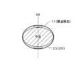
図22は、発電装置の構成を示す平面図、図23は図22の発電装置の概略側断面図である。
発電装置90は、発電機構部90a、電圧制御回路90b及びコンデンサ90cから構成されている。
発電機構部90aは、ユーザの手の振りなどによる回転錘91の回転によって発電を行うように構成されている。
即ち、図22および図23に示すように、発電機構部90aは、ベース92及びカバー93からなるケースを備え、このケース内にはベース92に固定された回転軸91aを中心として回転する回転錘91が設けられている。この回転錘91は、その重心が回転軸91a位置から大きくずれた位置となるような形状をなしている。さらに、回転錘91には歯車91bが固定されており、回転錘91の回転と共に歯車91bも回転するようになっている。
【0039】
また、上記ケース内には、歯車91bの回転に伴って回転する中間車94、及びこの中間車の回転に伴って回転する発電ロータ95が設けられている。これらの歯車91b、中間車94によって一般に輪列機構と称される回転運動伝達機構が形成されている。
発電ロータ95は、その回転軸と、この回転軸に直交する方向にN極とS極を有し回転軸に固定された永久磁石とから構成されている。さらに、発電ロータ95を両端部に間に挟むように略C字型の高透磁率材からなるステータ96が配置され、このステータ96の中央部分に導線が巻回されてコイル97が形成されている。
また、ベース92と回転錘91との間には回転錘91の回転を支持するベアリング98が配置されている。
また、ベース92の回転軸91aの周囲の空き領域には、電圧制御回路90b及びコンデンサ90cが配置されている。
【0040】
上述した発電機構部90aでは、次のようにして発電が行われる。即ち、ユーザの腕の振りなどにより回転錘91が回転すると、この回転運動が発電ロータ95に伝達されて発電ロータ95が回転する。
発電ロータ95が回転すると、発電ロータ95の永久磁石が回転し、永久磁石の両磁極は回転に伴ってステータ96の両端部と交互に対向し、対向した瞬間に永久磁石のN極から発せられた磁束はステータ96内を通ってS極に至る。これにより、コイル97の巻回軸に沿って瞬時に磁束が通過する。また、コイル97内を通過する磁束は、発電ロータ95の回転に同期して反転する。これにより、コイル97にはレンツの法則に基づく誘導起電力が発生して発電が行われ、コイル97の両端からは回転錘91の回転に伴って交流電力が出力される。
電圧制御回路90bは、図24に示すように、リミッタ回路101、ダイオード102、コンデンサ103及び昇圧回路104から構成されている。
リミッタ回路101は、コイル97に並列に接続され、所定の上限値を超えてコイル97の誘起電流が出力されないようにしている。これにより、大きな誘起電流が発生した場合も、後段に接続された回路の破壊等が防止される。
【0041】
ダイオード102とコンデンサ103は直列接続されて、この直列回路がリミッタ回路101に並列接続されている。このダイオード102によってコイル97に発生した誘起電流は整流され、コンデンサ103に一時的に蓄積される。
昇圧回路104は、周知のように入力電圧を所定倍して出力する回路で、その入力側はコンデンサ103の両端に接続されている。これにより、コンデンサ103に蓄積された電圧が、昇圧回路104によって昇圧されて出力される。
昇圧回路104の出力側にはコンデンサ90cが並列接続され、昇圧回路74から出力された電力はコンデンサ90cに蓄積される。
また、コンデンサ90cには、図示しない二次電池が接続されているので、昇圧回路104の出力によって二次電池も充電され、これらコンデンサ90c及び二次電池に蓄積された電気エネルギーが電源として供給される。
【0042】
従って、センサモジュール11は、ユーザが装着している際の運動エネルギーを利用して発電された電力によって駆動するので、半永久的な使用が可能になり、従来のような電池交換を行う必要がない。
また、センサモジュール11では、発電装置90と二次電池を併用することにより、非発電状態においても、機能を十分に発揮することができる。さらに、二次電池は発電装置90によって充電されるので、発電された電気エネルギーのうちセンサモジュールで消費できない分の電気エネルギーを有効に利用することができる。
また、発電装置90は、従来例の圧電素子を用いた発電装置に見られるようなクラックによる故障が生ずることなく、長時間安定した発電が可能となり、信頼性及び耐久性に優れている。
また、ステータ46に代えて、図25に示すように、発電ロータ45が挿入される略円形状の開口部96aを有した一体形状のステータ96Aを用いても良い。
さらに上記構成をピッチ計あるいは歩数計に採用することにより、電池交換の必要がなく、半永久的に使用が可能なピッチ計あるいは歩数計を構成することも可能である。
【0043】
[4.2]第2変形例
以上の説明においては、図2に示したように、センサモジュール11内に脈波検出センサおよび体動検出センサを設けていたが、図26に示すように、センサモジュール11内には脈波検出センサのみを設け、手首(装着部位)を介して対称な位置、すなわち、手首を介して同一軸AX上に体動検出センサ23(25)を設けるように構成することも可能である。
【0044】
[4.3]第3変形例
以上の説明においては、制御用プログラムが制御部5のROM310内にあらかじめ記憶されている場合について説明したが、各種磁気ディスク、光ディスク、メモリカードなどの記録媒体に制御用プログラムをあらかじめ記録し、これらの記録媒体から読み込み、インストールするように構成することも可能である。また、インターネット、LANなどのネットワークを介して制御用プログラムをダウンロードし、インストールして実行するように構成することも可能である。
【0045】
【発明の効果】
本発明によれば脈波センサと体動センサそれぞれの周波数分析結果から脈波成分を抽出するに際し、加速度が小さい体動成分が発生した場合でも、確実に脈波成分から体動成分を確実に除去して正確に脈拍数算出を行え、脈拍検出精度を向上させることができる。
【図面の簡単な説明】
【図1】第1実施形態の脈拍測定システムの概要構成図である。
【図2】センサモジュールの装着状態説明図である。
【図3】センサモジュールおよび携帯装置の概要構成ブロック図である。
【図4】センサモジュールの概略断面図である。
【図5】MPUが受信した脈波検出データの周波数分析結果の説明図である。
【図6】MPUが受信した体動検出データの周波数分析結果の説明図である。
【図7】周波数分析後の脈波検出データと周波数分析後の体動検出データとの差である差データの説明図である。
【図8】図8は、差データの周波数分析結果の説明図である。
【図9】脈波検出データの周波数分析結果の説明図である。
【図10】体動検出データの周波数分析結果の説明図である。
【図11】周波数分析後の脈波検出データと周波数分析後の体動検出データとの差である差データの説明図である。
【図12】適応フィルタの一例の概要構成ブロック図である。
【図13】脈波検出データの一例を時系列順に並べてグラフ化したものである。
【図14】図13の脈波検出データに対応する体動検出データを同一の時間軸で時系列順に並べてグラフ化したものである。
【図15】図13の脈波検出データおよび図14の体動検出データに対して適応フィルタを適用して得られた差データを時系列順に並べてグラフ化したものである。
【図16】図15の差データにFFTを施して得られた周波数分析結果である。
【図17】第2実施形態のセンサモジュールおよび携帯装置の概要構成ブロック図である。
【図18】センサモジュールの概略断面図である。
【図19】適応フィルタの一例の概要構成ブロック図である。
【図20】適応フィルタの一例の概要構成ブロック図である。
【図21】脈拍測定システムの応用例の説明図である。
【図22】発電装置の構成を示す平面図である。
【図23】図22における矢視方向に見た発電装置の概略側断面図である。
【図24】電圧制御回路の概要構成図である。
【図25】ロータの変形例の説明図である。
【図26】手首を介して同一軸上に体動検出センサを設けた場合の説明図である。
【符号の説明】
10…脈拍測定システム、11…センサモジュール、12…携帯装置、15…サポータ、21…脈波センサ、22…脈波信号増幅回路、23…体動センサ、24…体動信号増幅回路、25…体動センサ、26…体動信号増幅回路、27…A/D変換回路、28…無線送信回路、45…加速度センサ、51…無線受信回路、52…MPU、53…RAM、54…ROM、55…表示装置、56…操作部。[0001]
[Technical field to which the invention belongs]
The present invention relates to an information collection device and a pulse meter, and more particularly to an information collection device and a pulse meter that are worn on a part of a human body and used to measure a pulse during walking or running.
[Prior art]
2. Description of the Related Art Conventionally, a pulse wave meter is known that is mounted on a part of a human body and measures a pulse during walking or running.
For example,
The pulsometer disclosed in the above-mentioned
[0002]
[Patent Document 1]
Japanese Patent No. 2816944
[0003]
[Problems to be solved by the invention]
In the above-described conventional pulse meter, the body motion component is detected by the acceleration sensor. Therefore, the motion with low acceleration cannot be detected even when the influence on the pulse wave signal is large, and the correct pulse wave component can be extracted. There was a bug that it was not possible.
As an operation with such a small acceleration in a wristwatch type pulse shape, there is an operation of holding or opening a hand. When the hand is held or opened, the wrist diameter changes on the order of several millimeters.
This effect appears greatly in the pulse wave component but does not appear in the body motion component. For this reason, there has been a problem that the pulse wave component cannot be extracted accurately and the correct pulse cannot be measured.
Therefore, an object of the present invention is to provide an information collection device and a pulse meter for accurately calculating a pulse rate by reliably removing a body motion component from a pulse wave component even when a body motion component with small acceleration occurs. Is to provide.
[0005]
[Means for Solving the Problems]
In order to solve the above-mentioned problem, in an information collecting apparatus that is worn on a human body and collects information on a pulse, a body movement component generated in accordance with a change in the shape of the living body surface of the wearing site is detected and a first body movement detection signal is output. A first body motion detecting unit, a second body motion detecting unit for detecting a body motion component generated in accordance with the movement of the human body and outputting a second body motion detection signal, and detecting a pulse wave component to detect a pulse wave A pulse wave detection unit that outputs a signal, and when the movement of the human body is detected, a body movement component is removed from the pulse wave detection signal based on the second body movement detection signal, and the human body When no movement is detected, a body motion component is removed from the pulse wave detection signal based on the first body motion detection signal.
According to the above configuration, the first body motion detection unit detects a body motion component that is generated along with a change in the shape of the living body surface of the wearing site, and outputs a first body motion detection signal.
A second body motion detection unit detects a body motion component generated with the movement of the human body and outputs a second body motion detection signal.
The pulse wave detection unit detects a pulse wave component and outputs a pulse wave detection signal.
When the movement of the human body is detected, the information collecting device removes a body movement component from the pulse wave detection signal based on the second body movement detection signal, and the movement of the human body is not detected. The body motion component is removed from the pulse wave detection signal based on the first body motion detection signal.
[0006]
In these cases, the living body surface may be a wrist surface.
The first body motion detection unit may include any one of a pressure sensor, a load sensor, and a displacement sensor.
Furthermore, the second body motion detection unit may include an acceleration sensor.
Furthermore, the pulse wave detection unit may include a pulse wave sensor, and the detection position of the body motion detection unit may be disposed in the vicinity of the pulse wave sensor.
Further, the pulse wave detection unit includes a pulse wave sensor, and the pulse wave sensor is located on the back side or the same surface side of the wearing site, on the same axis and passing through the detection position of the pulse wave sensor. You may make it arrange | position the detection position of a 1 body motion detection part and a said 2nd body motion detection part.
[0007]
The pulse meter is based on the receiving unit that receives the information collected from the information collecting device described above, and the first body motion detection signal, the second body motion detection signal, and the pulse wave detection signal included in the received information. And a pulse rate calculation unit for calculating the pulse rate.
According to the above configuration, the receiving unit receives information collected from the information collecting apparatus described above.
Thereby, the pulse rate calculation unit calculates the pulse rate based on the first body motion detection signal, the second body motion detection signal, and the pulse wave detection signal included in the received information.
[0008]
In this case, a transmitter that transmits the collected information to the outside may be provided.
In addition, the pulse rate calculation unit performs frequency analysis on the body motion detection signal to generate first frequency analysis data, and performs frequency analysis on the pulse wave detection signal to generate second frequency analysis data. And a removal processing unit that performs a subtraction process on the first frequency analysis data with respect to the second frequency analysis data.
[0012]
DETAILED DESCRIPTION OF THE INVENTION
Next, preferred embodiments of the present invention will be described with reference to the drawings.
[1] First embodiment
FIG. 1 is a schematic configuration diagram of a pulse measurement system according to the first embodiment.
The
FIG. 2 is an explanatory diagram of the mounting state of the sensor module.
The
FIG. 3 is a schematic configuration block diagram of the sensor module and the portable device.
The
[0013]
The
The pulse wave
The
[0014]
The body motion
The A /
The
[0015]
Here, the mechanical configuration of the
FIG. 4 is a schematic cross-sectional view of the
The
A
Further, the
A
[0016]
Next, the configuration of the
On the other hand, as illustrated in FIG. 3, the
The
The
The
The
The
The
[0017]
Next, a pulse rate calculation process in the MPU that has received the pulse wave detection data and the body motion detection data will be described.
FIG. 5 is an explanatory diagram of the frequency analysis result of the pulse wave detection data received by the
FIG. 6 is an explanatory diagram of the frequency analysis result of the body motion detection data received by the
First, when the
Subsequently, when a predetermined number of data is stored in the
[0018]
FIG. 7 is an explanatory diagram of difference data which is a difference between pulse wave detection data after frequency analysis and body motion detection data after frequency analysis.
The
FIG. 8 is an explanatory diagram of the frequency analysis result of the difference data.
As a result, the frequency analysis result as the obtained difference data is substantially derived from the output signal (pulse wave component + body motion component) of the pulse wave sensor, for example, by deforming the wrist by the operation of grasping and opening the hand ( The pulse wave data corresponding to the pulse wave component is mainly obtained by removing the body motion component resulting from the increase or decrease of the wrist diameter.
Further, the
Then, the
As described above, according to the first embodiment, the body generated due to the deformation of the wearing portion represented by the deformation of the wrist (increase or decrease in the diameter of the wrist) due to the operation of grasping or opening the hand. Dynamic components can be detected and grasped reliably. For this reason, the body motion component resulting from the deformation | transformation of a mounting | wearing site | part can be removed reliably, and an exact pulse wave component detection and by extension, an exact pulse rate measurement can be performed.
[0019]
[1.1] First modification
In the above description, the difference data is calculated by subtracting the body motion detection data from the pulse wave detection data before performing the frequency analysis (FFT). However, in the first modification, the pulse wave detection data and the body It is a modification in the case of calculating difference data after performing frequency analysis on motion detection data. Hereinafter, the first modification will be described.
In the first modification, the
Next, the
Then, the harmonic component of the pulse wave is extracted from the obtained difference data, and the pulse rate is calculated from the frequency.
[0020]
Next, a specific pulse rate calculation process will be described.
FIG. 9 is an explanatory diagram of the frequency analysis result of the pulse wave detection data.
FIG. 10 is an explanatory diagram of the frequency analysis result of the body motion detection data.
First, the
FIG. 11 is an explanatory diagram of difference data, which is a difference between pulse wave detection data after frequency analysis and body motion detection data after frequency analysis.
Next, the
[0021]
As a result, the frequency analysis result as the obtained difference data is substantially derived from the output signal (pulse wave component + body motion component) of the pulse wave sensor, for example, by deforming the wrist by the operation of grasping and opening the hand ( The pulse wave data corresponding to the pulse wave component is mainly obtained by removing the body motion component resulting from the increase or decrease of the wrist diameter.
Further, the
Then, the
As described above, according to the first modified example, the body movement caused by the deformation of the wearing part represented by the deformation of the wrist (increase / decrease in the diameter of the wrist) by the operation of grasping and opening the hand. Components can be detected and grasped reliably. For this reason, a body motion component can be removed reliably, and an accurate pulse wave component detection and an accurate pulse rate measurement can be performed.
[0022]
[1.2] Second modification
In the above description, as the internal processing of the MPU, the difference data is calculated by subtracting the body motion detection data from the pulse wave detection data before or after performing the frequency analysis (FFT). These are the modifications in the case of removing a body motion component from pulse wave detection data using an adaptive filter.
FIG. 12 shows a schematic configuration block diagram of an example of the adaptive filter.
The
The filter
[0023]
The synthesizing
Next, a more specific pulse rate calculation process in the second modification will be described.
FIG. 13 is a graph showing an example of pulse wave detection data arranged in chronological order.
FIG. 14 is a graph in which body motion detection data corresponding to the pulse wave detection data of FIG. 13 is arranged in time series on the same time axis.
First, the
[0024]
Further, the
As a result, the filter
Thereby, the
[0025]
FIG. 15 is a graph in which difference data obtained by applying an adaptive filter to the pulse wave detection data of FIG. 13 and the body motion detection data of FIG. 14 are arranged in chronological order.
Next, the
FIG. 16 shows the frequency analysis result obtained by performing FFT on the difference data of FIG.
As a result, the obtained frequency analysis result is substantially deformed from the output signal (pulse wave component + body motion component) of the pulse wave sensor by deforming the wrist by grasping and opening the hand (increasing or decreasing the wrist diameter). The body motion component generated due to the deformation of the wearing part represented by the above is removed, that is, the pulse wave data mainly corresponding to the pulse wave component.
Further, the
Then, the
As described above, according to the second modified example, body movement caused by deformation of the wearing part represented by wrist deformation (increase / decrease in wrist diameter) due to the operation of grasping and opening the hand. Components can be detected and grasped reliably. For this reason, a body motion component can be removed reliably, and an accurate pulse wave component detection and, consequently, an accurate pulse rate can be measured.
[0026]
[2] Second embodiment
FIG. 17 is a schematic configuration block diagram of the sensor module and the portable device of the second embodiment. In FIG. 17, the same components as those in the first embodiment in FIG.
The
The
[0027]
The pulse wave
The first
The first body motion
The second
[0028]
The second body motion
The A /
[0029]
The
FIG. 18 is a schematic cross-sectional view of the sensor module. In FIG. 18, the same parts as those in FIG. 4 are denoted by the same reference numerals.
The
[0030]
A
On the upper side of the
Further, the
In addition, a first
[0031]
In the second embodiment, the body motion component is removed from the pulse wave detection data using an adaptive filter.
FIG. 19 is a schematic block diagram of an example of an adaptive filter.
The
Here, the filter
The filter
[0032]
Accordingly, the first adaptive filter
On the other hand, the second adaptive filter
The synthesizing
[0033]
[2.1] Modification
Next, a modification of the second embodiment will be described.
In this modification, the second embodiment extracts a pulse wave component using all of the pulse wave detection data (= pulse wave component + body motion component), the first body motion detection data, and the second body motion detection data. In contrast, in the first modified example, the influence of the first body motion detection data corresponding to the body motion component caused by the shape change of the wearing portion is large at rest, but small at the time of exercise (walking, running), On the contrary, the second body motion detection data is a modified example using the fact that the influence of the second body motion detection data is small at rest, but is large at the time of exercise (walking, running).
When there is no large body motion, that is, at rest, a pulse wave component is extracted using the pulse wave detection data and the first body motion detection data. On the other hand, when there is a large body motion, that is, during exercise, a pulse wave component is extracted using the pulse wave detection data and the second body motion detection data.
[0034]
Accordingly, since only one adaptive filter coefficient generation unit needs to be provided, the apparatus configuration and processing are simplified.
FIG. 20 is a schematic block diagram of an example of an adaptive filter.
The
The body movement presence /
As a result, when it is determined that there is no large body movement, the
Therefore, the filter
[0035]
The synthesizing
On the other hand, when the body movement presence /
Therefore, the filter
The
As described above, according to the modification of the second embodiment, the apparatus configuration can be simplified, the processing can be simplified, and the pulse wave component can be reliably extracted. As a result, the pulse rate can be accurately detected.
[0036]
[3] Application examples
Next, an application example of the pulse measurement system of the present invention will be described.
FIG. 21 is an explanatory diagram of an application example of the pulse measurement system.
As shown in FIG. 21, when the user is at home, the
Thereby, the pulse wave detection data and the body motion detection data detected by the
[0037]
When the user is out, the
Thereby, the pulse wave detection data and the body motion detection data detected by the
Thereafter, by connecting the
[0038]
[4] Modification of embodiment
[4.1] First modification
In the above description, the case where a battery is used as the power source of the sensor module has been described. However, a small power generator may be used instead of the battery.
22 is a plan view showing the configuration of the power generation apparatus, and FIG. 23 is a schematic side sectional view of the power generation apparatus of FIG.
The
The
That is, as shown in FIGS. 22 and 23, the
[0039]
Further, an
The
A bearing 98 that supports the rotation of the
In addition, a
[0040]
In the
When the
The
The
[0041]
The
The
A
In addition, since a secondary battery (not shown) is connected to the
[0042]
Therefore, since the
Moreover, in the
Further, the
Further, instead of the stator 46, as shown in FIG. 25, an
Further, by adopting the above configuration in a pitch meter or a pedometer, it is possible to configure a pitch meter or a pedometer that can be used semi-permanently without the need for battery replacement.
[0043]
[4.2] Second modification
In the above description, the pulse wave detection sensor and the body motion detection sensor are provided in the
[0044]
[4.3] Third modification
In the above description, the case where the control program is stored in advance in the ROM 310 of the
[0045]
【The invention's effect】
According to the present invention, when extracting a pulse wave component from the frequency analysis result of each of the pulse wave sensor and the body motion sensor, even if a body motion component with a small acceleration is generated, the body motion component is reliably ensured from the pulse wave component. By removing the pulse rate, the pulse rate can be calculated accurately, and the pulse detection accuracy can be improved.
[Brief description of the drawings]
FIG. 1 is a schematic configuration diagram of a pulse measurement system according to a first embodiment.
FIG. 2 is an explanatory diagram of a mounting state of a sensor module.
FIG. 3 is a schematic configuration block diagram of a sensor module and a portable device.
FIG. 4 is a schematic cross-sectional view of a sensor module.
FIG. 5 is an explanatory diagram of a frequency analysis result of pulse wave detection data received by the MPU.
FIG. 6 is an explanatory diagram of frequency analysis results of body motion detection data received by an MPU.
FIG. 7 is an explanatory diagram of difference data which is a difference between pulse wave detection data after frequency analysis and body motion detection data after frequency analysis.
FIG. 8 is an explanatory diagram of frequency analysis results of difference data.
FIG. 9 is an explanatory diagram of a frequency analysis result of pulse wave detection data.
FIG. 10 is an explanatory diagram of a frequency analysis result of body motion detection data.
FIG. 11 is an explanatory diagram of difference data, which is a difference between pulse wave detection data after frequency analysis and body motion detection data after frequency analysis.
FIG. 12 is a schematic configuration block diagram of an example of an adaptive filter.
FIG. 13 is a graph showing an example of pulse wave detection data arranged in chronological order.
14 is a graph in which body motion detection data corresponding to the pulse wave detection data of FIG. 13 is arranged in time series on the same time axis.
15 is a graph in which difference data obtained by applying an adaptive filter to the pulse wave detection data of FIG. 13 and the body motion detection data of FIG. 14 are arranged in chronological order.
FIG. 16 is a frequency analysis result obtained by performing FFT on the difference data in FIG. 15;
FIG. 17 is a schematic configuration block diagram of a sensor module and a portable device according to a second embodiment.
FIG. 18 is a schematic cross-sectional view of a sensor module.
FIG. 19 is a schematic configuration block diagram of an example of an adaptive filter.
FIG. 20 is a schematic configuration block diagram of an example of an adaptive filter.
FIG. 21 is an explanatory diagram of an application example of a pulse measurement system.
FIG. 22 is a plan view showing the configuration of the power generation device.
23 is a schematic sectional side view of the power generator as viewed in the direction of the arrow in FIG.
FIG. 24 is a schematic configuration diagram of a voltage control circuit.
FIG. 25 is an explanatory diagram of a modified example of the rotor.
FIG. 26 is an explanatory diagram when a body motion detection sensor is provided on the same axis through the wrist.
[Explanation of symbols]
DESCRIPTION OF
Claims (9)
Translated fromJapanese装着部位の生体表面の形状変化に伴って発生する体動成分を検出し第1体動検出信号を出力する第1体動検出部と、
前記人体の動きに伴って発生する体動成分を検出し第2体動検出信号を出力する第2体動検出部と、
脈波成分を検出し脈波検出信号を出力する脈波検出部と、
を備え、
前記人体の動きが検出される場合には、前記第2体動検出信号に基づいて前記脈波検出信号から体動成分を除去し、
前記人体の動きが検出されない場合には、前記第1体動検出信号に基づいて前記脈波検出信号から体動成分を除去する、
ことを特徴とする情報収集装置。In an information collection device that is worn on the human body and collects information about the pulse,
A first body motion detection unit that detects a body motion component generated with a change in the shape of the living body surface of the wearing site and outputs a first body motion detection signal;
A second body motion detection unit that detects a body motion component generated in accordance with the movement of the human body and outputs a second body motion detection signal;
A pulse wave detector that detects a pulse wave component and outputs a pulse wave detection signal;
With
When the movement of the human body is detected, a body motion component is removed from the pulse wave detection signal based on the second body motion detection signal,
When the movement of the human body is not detected, a body motion component is removed from the pulse wave detection signal based on the first body motion detection signal.
An information collecting apparatus characterized by that.
前記生体表面は、手首の表面であることを特徴とする情報収集装置。The information collection device according to claim 1,
The information collecting apparatus according to claim 1, wherein the surface of the living body is a surface of a wrist.
前記第1体動検出部は、圧力センサ、荷重センサあるいは変位センサのいずれかを備えたことを特徴とする情報収集装置。In the information gathering device according to claim 1 or 2,
The information collecting apparatus according to claim 1, wherein the first body motion detection unit includes any one of a pressure sensor, a load sensor, and a displacement sensor.
前記第2体動検出部は、加速度センサを備えたことを特徴とする情報収集装置。The information collection device according to any one of claims 1 to 3,
The information gathering apparatus, wherein the second body motion detection unit includes an acceleration sensor.
前記脈波検出部は、脈波センサを備え、
前記脈波センサの近傍に前記体動検出部の検出位置を配置したことを特徴とする情報収集装置。The information collection device according to any one of claims 1 to 4,
The pulse wave detection unit includes a pulse wave sensor,
An information collecting apparatus, wherein a detection position of the body motion detection unit is arranged in the vicinity of the pulse wave sensor.
前記脈波検出部は、脈波センサを備え、
前記脈波センサに対し、装着部位の背面側あるいは同一面側であって前記脈波センサの検出位置を通る同一軸上近傍に前記第1体動検出部および前記第2体動検出部の検出位置を配置したことを特徴とする情報収集装置。The information collection device according to claim 5,
The pulse wave detection unit includes a pulse wave sensor,
Detection of the first body motion detection unit and the second body motion detection unit in the vicinity of the same axis passing through the detection position of the pulse wave sensor on the back surface side or the same surface side of the wearing site with respect to the pulse wave sensor An information collecting apparatus characterized by arranging a position.
受信した情報に含まれる前記第1体動検出信号、前記第2体動検出信号および脈波検出信号に基づいて脈拍数を算出する脈拍数算出部と、
を備えたことを特徴とする脈拍計。A receiving unit for receiving information collected from the information collecting apparatus according to claim 1;
A pulse rate calculator that calculates a pulse rate based on the first body motion detection signal, the second body motion detection signal, and the pulse wave detection signal included in the received information;
A pulse meter characterized by comprising:
収集した情報を外部に送信する送信部を備えたことを特徴とする脈拍計。The pulse meter according to claim 7,
A pulse meter comprising a transmitter for transmitting the collected information to the outside.
前記脈拍数算出部は、前記体動検出信号を周波数分析し第1周波数分析データを生成する第1周波数分析部と、
前記脈波検出信号を周波数分析し、第2周波数分析データを生成する第2周波数分析部と、
前記第2周波数分析データに対する前記第1周波数分析データの減算処理を行う除去処理部を備えたことを特徴とする脈拍計。In the pulse meter according to claim 7 or 8,
The pulse rate calculation unit performs a frequency analysis on the body motion detection signal and generates first frequency analysis data;
A frequency analysis of the pulse wave detection signal, a second frequency analysis unit for generating second frequency analysis data;
A pulse meter, comprising: a removal processing unit that performs a subtraction process on the first frequency analysis data with respect to the second frequency analysis data.
Priority Applications (3)
| Application Number | Priority Date | Filing Date | Title |
|---|---|---|---|
| JP2003075838AJP3815448B2 (en) | 2003-03-19 | 2003-03-19 | Information collection device and pulse meter |
| US10/803,088US20040236233A1 (en) | 2003-03-19 | 2004-03-18 | Information-gathering device and pulse meter |
| CN200410039955.4ACN1275570C (en) | 2003-03-19 | 2004-03-19 | Information collector and pulse meter |
Applications Claiming Priority (1)
| Application Number | Priority Date | Filing Date | Title |
|---|---|---|---|
| JP2003075838AJP3815448B2 (en) | 2003-03-19 | 2003-03-19 | Information collection device and pulse meter |
Publications (3)
| Publication Number | Publication Date |
|---|---|
| JP2004283228A JP2004283228A (en) | 2004-10-14 |
| JP2004283228A5 JP2004283228A5 (en) | 2005-09-02 |
| JP3815448B2true JP3815448B2 (en) | 2006-08-30 |
Family
ID=33291051
Family Applications (1)
| Application Number | Title | Priority Date | Filing Date |
|---|---|---|---|
| JP2003075838AExpired - Fee RelatedJP3815448B2 (en) | 2003-03-19 | 2003-03-19 | Information collection device and pulse meter |
Country Status (3)
| Country | Link |
|---|---|
| US (1) | US20040236233A1 (en) |
| JP (1) | JP3815448B2 (en) |
| CN (1) | CN1275570C (en) |
Families Citing this family (39)
| Publication number | Priority date | Publication date | Assignee | Title |
|---|---|---|---|---|
| JP3815448B2 (en)* | 2003-03-19 | 2006-08-30 | セイコーエプソン株式会社 | Information collection device and pulse meter |
| US7993276B2 (en)* | 2004-10-15 | 2011-08-09 | Pulse Tracer, Inc. | Motion cancellation of optical input signals for physiological pulse measurement |
| US20070049836A1 (en)* | 2004-12-07 | 2007-03-01 | Yu-Yu Chen | Electronic wristwatch-type exercise signal detecting apparatus |
| US20060122521A1 (en)* | 2004-12-07 | 2006-06-08 | Yu-Yu Chen | Electronic wristwatch-type exercise signal detecting apparatus |
| WO2006067690A2 (en)* | 2004-12-22 | 2006-06-29 | Philips Intellectual Property & Standards Gmbh | Device for measuring a user´s heart rate |
| DE102005019753A1 (en)* | 2005-04-28 | 2006-11-09 | Braun Gmbh | Sphygmomanometer and chip card for this |
| WO2007072425A2 (en)* | 2005-12-20 | 2007-06-28 | Koninklijke Philips Electronics, N.V. | Device for detecting and warning of a medical condition |
| CN1985751B (en)* | 2005-12-21 | 2010-05-05 | 香港理工大学 | Wearable physiological sign detector, physiological sign telemetering and alarming system |
| EP1908401A1 (en)* | 2006-10-06 | 2008-04-09 | ETA SA Manufacture Horlogère Suisse | Method and device for measuring the heartbeat during rythmic sport practice |
| JP5060186B2 (en)* | 2007-07-05 | 2012-10-31 | 株式会社東芝 | Pulse wave processing apparatus and method |
| JP5076962B2 (en)* | 2008-02-25 | 2012-11-21 | セイコーエプソン株式会社 | Biological information processing apparatus, control method and control program for biological information processing apparatus |
| AU2009246442B2 (en)* | 2008-05-14 | 2015-02-12 | Heartmiles, Llc. | Physical activity monitor and data collection unit |
| EP2347360A1 (en)* | 2008-08-20 | 2011-07-27 | Espenusa Holding, LLC | Physical activity tracking and rewards allocation system |
| JP5315948B2 (en)* | 2008-11-19 | 2013-10-16 | 富士通株式会社 | Pulse rate calculation program, pulse rate calculation device, pulse rate calculation method, and portable terminal device |
| JP5369726B2 (en)* | 2009-02-02 | 2013-12-18 | セイコーエプソン株式会社 | Pulsation detection device and pulsation detection method |
| KR100997444B1 (en)* | 2009-11-17 | 2010-11-30 | (주)에이치쓰리시스템 | Photoplethysmography apparatus |
| US20120283535A1 (en)* | 2009-11-30 | 2012-11-08 | Israel Sarussi | Method and system for pulse measurement |
| CN102389295A (en) | 2010-07-12 | 2012-03-28 | 罗姆股份有限公司 | Wireless plethysmogram sensor unit, a processing unit for plethysmogram and a plethysmogram system |
| JP2012019811A (en)* | 2010-07-12 | 2012-02-02 | Rohm Co Ltd | Biological data measuring device |
| JP5716466B2 (en)* | 2011-03-10 | 2015-05-13 | セイコーエプソン株式会社 | Filter device and pulsation detection device |
| JP5742441B2 (en)* | 2011-05-06 | 2015-07-01 | セイコーエプソン株式会社 | Biological information processing device |
| US9109902B1 (en) | 2011-06-13 | 2015-08-18 | Impact Sports Technologies, Inc. | Monitoring device with a pedometer |
| JP6116017B2 (en)* | 2012-01-16 | 2017-04-19 | ヴァレンセル, インコーポレイテッドValencell, Inc. | Reduction of physiological measurement error by inertia rhythm |
| WO2013109389A1 (en) | 2012-01-16 | 2013-07-25 | Valencell, Inc. | Physiological metric estimation rise and fall limiting |
| JP5821658B2 (en)* | 2012-01-25 | 2015-11-24 | オムロンヘルスケア株式会社 | Measuring apparatus and measuring method |
| JP5454593B2 (en)* | 2012-01-26 | 2014-03-26 | トヨタ自動車株式会社 | Heart rate signal processing apparatus and heart rate signal processing method |
| CN102885617B (en)* | 2012-11-01 | 2015-01-07 | 刘维明 | Physical fitness detection device for power supply by using human motion and detection method |
| CN102988036B (en)* | 2012-12-26 | 2014-08-06 | 中国科学院自动化研究所 | Method for measuring pulse rate |
| WO2014109982A2 (en) | 2013-01-09 | 2014-07-17 | Valencell Inc. | Cadence detection based on inertial harmonics |
| CN104055505B (en)* | 2013-03-18 | 2019-03-22 | 精工爱普生株式会社 | Bioinformation detecting device |
| CN104055494A (en)* | 2014-06-20 | 2014-09-24 | 张新瑜 | Running device suitable for middle-aged and aged people |
| US9179849B1 (en) | 2014-07-25 | 2015-11-10 | Impact Sports Technologies, Inc. | Mobile plethysmographic device |
| JP2017051554A (en)* | 2015-09-11 | 2017-03-16 | 株式会社東芝 | Pulse wave measuring device, pulse wave measuring system, and signal processing method |
| JP2017104239A (en)* | 2015-12-08 | 2017-06-15 | ルネサスエレクトロニクス株式会社 | Electronic device |
| JP6260630B2 (en)* | 2016-02-04 | 2018-01-17 | セイコーエプソン株式会社 | Biological information detection device |
| WO2017208645A1 (en)* | 2016-05-31 | 2017-12-07 | 国立大学法人九州大学 | Flow volume measuring device, flow volume measuring method, pressure measuring device, and pressure measuring method |
| CN105997043B (en)* | 2016-06-24 | 2018-11-20 | 中国科学院电子学研究所 | A kind of pulse frequency extracting method based on wrist wearable device |
| CN111481169B (en)* | 2019-12-13 | 2023-03-07 | 重庆工商大学 | Children monitoring system based on from electricity generation mechanism |
| CN111528825A (en)* | 2020-05-14 | 2020-08-14 | 浙江大学 | Photoelectric volume pulse wave signal optimization method |
Family Cites Families (12)
| Publication number | Priority date | Publication date | Assignee | Title |
|---|---|---|---|---|
| JPH0315502U (en)* | 1989-06-28 | 1991-02-15 | ||
| GB9011887D0 (en)* | 1990-05-26 | 1990-07-18 | Le Fit Ltd | Pulse responsive device |
| DE59306200D1 (en)* | 1992-12-05 | 1997-05-22 | Avl Medical Instr Ag | SENSOR AND DEVICE FOR MEASURING BLOOD PRESSURE |
| US5778882A (en)* | 1995-02-24 | 1998-07-14 | Brigham And Women's Hospital | Health monitoring system |
| JPH08317912A (en)* | 1995-03-23 | 1996-12-03 | Seiko Instr Inc | Pulse meter |
| JP3523978B2 (en)* | 1997-03-18 | 2004-04-26 | セイコーエプソン株式会社 | Pulse meter |
| EP1405593B1 (en)* | 1997-09-05 | 2011-08-10 | Seiko Epson Corporation | Optical diagnostic measurement device |
| JP2000051164A (en)* | 1998-08-07 | 2000-02-22 | Seiko Instruments Inc | Pulse wave detector |
| JP3543778B2 (en)* | 2000-10-16 | 2004-07-21 | オムロンヘルスケア株式会社 | Pedometer |
| EP1297784B8 (en)* | 2001-09-28 | 2011-01-12 | CSEM Centre Suisse d'Electronique et de Microtechnique SA - Recherche et Développement | Method and device for pulse rate detection |
| JP3801163B2 (en)* | 2003-03-07 | 2006-07-26 | セイコーエプソン株式会社 | Body motion detection device, pitch meter, pedometer, wristwatch type information processing device, control method, and control program |
| JP3815448B2 (en)* | 2003-03-19 | 2006-08-30 | セイコーエプソン株式会社 | Information collection device and pulse meter |
- 2003
- 2003-03-19JPJP2003075838Apatent/JP3815448B2/ennot_activeExpired - Fee Related
- 2004
- 2004-03-18USUS10/803,088patent/US20040236233A1/ennot_activeAbandoned
- 2004-03-19CNCN200410039955.4Apatent/CN1275570C/ennot_activeExpired - Fee Related
Also Published As
| Publication number | Publication date |
|---|---|
| CN1275570C (en) | 2006-09-20 |
| JP2004283228A (en) | 2004-10-14 |
| CN1531901A (en) | 2004-09-29 |
| US20040236233A1 (en) | 2004-11-25 |
Similar Documents
| Publication | Publication Date | Title |
|---|---|---|
| JP3815448B2 (en) | Information collection device and pulse meter | |
| JP6020174B2 (en) | Mobile communication device and communication method | |
| JP3936833B2 (en) | Body motion sensing device and body motion sensing system | |
| EP0729726B1 (en) | Pulse rate meter | |
| CN101596107B (en) | Method for realizing detection of heart rate by mobile terminal and mobile terminal thereof | |
| CN110383021A (en) | Use the blood pressure measuring system of resistance-type force sensor array | |
| WO2007072239A3 (en) | Apparatus for monitoring a person's heart rate and/or heart rate variation; wristwatch comprising the same | |
| WO2015004914A1 (en) | Biometric information detection device | |
| EP1962685A4 (en) | METHOD AND APPARATUS FOR MEASURING AND ANALYZING MOVEMENTS OF A HUMAN BEING OR ANIMAL USING SOUND SIGNALS | |
| WO2017074713A1 (en) | Non-invasive continuous blood pressure monitoring with reduced motion artifacts | |
| JPH11276448A (en) | Signal extraction device and signal extraction method | |
| JP2013244287A (en) | Specimen information processor | |
| JP2010000286A (en) | Biological information collecting device | |
| JP4021137B2 (en) | Body motion sensing device | |
| Li et al. | Machine learning-assisted wearable triboelectric-electromagnetic vibration sensor for monitoring human rehabilitation training | |
| JP2000051164A (en) | Pulse wave detector | |
| CA3207258A1 (en) | Cardiovascular monitoring system | |
| JP4044376B2 (en) | Temperature measurement method, object detection method and object detection apparatus for vibration type level sensor | |
| Beyaz et al. | A turbine-based MEMS sensor for spirometry with wearable devices | |
| JP2011250945A (en) | Gait analysis method, system, and apparatus | |
| JP2008200432A (en) | Vibration detecting device | |
| KR20100073843A (en) | Apparatus for measuring bio-information using energy harvest | |
| US11715362B2 (en) | Integrated sensing and actuation module for wristband enabling identification and/or compensation for band tightness | |
| JP2005131426A (en) | Pulse meter, pulse meter control method, wristwatch type information device, control program, and recording medium | |
| CN206102633U (en) | Remote consultation system |
Legal Events
| Date | Code | Title | Description |
|---|---|---|---|
| A521 | Request for written amendment filed | Free format text:JAPANESE INTERMEDIATE CODE: A523 Effective date:20050228 | |
| A621 | Written request for application examination | Free format text:JAPANESE INTERMEDIATE CODE: A621 Effective date:20050228 | |
| A977 | Report on retrieval | Free format text:JAPANESE INTERMEDIATE CODE: A971007 Effective date:20051220 | |
| A131 | Notification of reasons for refusal | Free format text:JAPANESE INTERMEDIATE CODE: A131 Effective date:20051227 | |
| A521 | Request for written amendment filed | Free format text:JAPANESE INTERMEDIATE CODE: A523 Effective date:20060216 | |
| TRDD | Decision of grant or rejection written | ||
| A01 | Written decision to grant a patent or to grant a registration (utility model) | Free format text:JAPANESE INTERMEDIATE CODE: A01 Effective date:20060516 | |
| A61 | First payment of annual fees (during grant procedure) | Free format text:JAPANESE INTERMEDIATE CODE: A61 Effective date:20060529 | |
| R150 | Certificate of patent or registration of utility model | Free format text:JAPANESE INTERMEDIATE CODE: R150 | |
| FPAY | Renewal fee payment (event date is renewal date of database) | Free format text:PAYMENT UNTIL: 20100616 Year of fee payment:4 | |
| FPAY | Renewal fee payment (event date is renewal date of database) | Free format text:PAYMENT UNTIL: 20110616 Year of fee payment:5 | |
| FPAY | Renewal fee payment (event date is renewal date of database) | Free format text:PAYMENT UNTIL: 20110616 Year of fee payment:5 | |
| FPAY | Renewal fee payment (event date is renewal date of database) | Free format text:PAYMENT UNTIL: 20120616 Year of fee payment:6 | |
| FPAY | Renewal fee payment (event date is renewal date of database) | Free format text:PAYMENT UNTIL: 20130616 Year of fee payment:7 | |
| FPAY | Renewal fee payment (event date is renewal date of database) | Free format text:PAYMENT UNTIL: 20130616 Year of fee payment:7 | |
| S531 | Written request for registration of change of domicile | Free format text:JAPANESE INTERMEDIATE CODE: R313531 | |
| R350 | Written notification of registration of transfer | Free format text:JAPANESE INTERMEDIATE CODE: R350 | |
| LAPS | Cancellation because of no payment of annual fees |