JP3815029B2 - Wireless communication device - Google Patents
Wireless communication deviceDownload PDFInfo
- Publication number
- JP3815029B2 JP3815029B2JP04954798AJP4954798AJP3815029B2JP 3815029 B2JP3815029 B2JP 3815029B2JP 04954798 AJP04954798 AJP 04954798AJP 4954798 AJP4954798 AJP 4954798AJP 3815029 B2JP3815029 B2JP 3815029B2
- Authority
- JP
- Japan
- Prior art keywords
- unit
- wireless communication
- communication unit
- image
- image data
- Prior art date
- Legal status (The legal status is an assumption and is not a legal conclusion. Google has not performed a legal analysis and makes no representation as to the accuracy of the status listed.)
- Expired - Fee Related
Links
- 230000005540biological transmissionEffects0.000description5
- 230000005236sound signalEffects0.000description5
- 238000010586diagramMethods0.000description4
- 230000009977dual effectEffects0.000description3
- 239000000284extractSubstances0.000description3
- 238000000034methodMethods0.000description2
- 230000003044adaptive effectEffects0.000description1
- 230000000694effectsEffects0.000description1
- 238000009434installationMethods0.000description1
Images

Landscapes
- Telephone Function (AREA)
- Telephonic Communication Services (AREA)
- Facsimile Transmission Control (AREA)
- Mobile Radio Communication Systems (AREA)
Description
Translated fromJapanese【0001】
【発明の属する技術分野】
本発明は、無線通信する画像データを、通信回線を介して通信する無線通信装置に関する。
【0002】
【従来の技術】
従来から、無線通信装置として、親機と子機が無線接続されているコードレス電話機が、一般家庭に普及しているが、近時では、子機をファクシミリ装置とする一方、親機側に通信回線を接続したシステムが開発されており、これによれば、ファクシミリ装置は画像の読取機能(スキャナ機能)と画像の記録機能(プリンタ機能)を備えるだけでよいため、小型化が図れ、また、配線を気にせず設置場所の移動が自由にできるようになっている。
【0003】
【発明が解決しようとする課題】
ところが、上記したファクシミリ通信する場合の無線通信装置の親機側は、予め、通信回線(電話回線)を接続してファクシミリ通信をする機能と、子機であるファクシミリ装置と無線通信する機能とを備えていなければならなかった。また、子機であるPHS等の音声通信装置によって、親機を介した通話をも可能とする場合、親機の構成及び制御が複雑になっていた。
【0004】
本発明は、このような事情に鑑みてなされたものであり、通信回線を接続する画像通信部に対し無線通信部を簡易に接続できる構成とし、通信制御が複雑にならずに済むようにした無線通信装置を提供することを目的とする。
【0005】
【課題を解決するための手段】
上記目的を達成するために、本発明の請求項1に記載の無線通信装置は、画像データを電話回線などの通信回線を通じて通信する画像通信部には外付け電話機を接続するための電話端子と、画像データを無線通信部との間で送受するための画像端子とを備えており、この画像通信部に、上記電話端子と上記画像端子とを通じて、画像データを無線通信する無線通信部を接続した構成とされ、無線通信部には、画像データを記憶する記憶手段を備える一方、画像通信部には、無線通信部の記憶手段を、バスを通じて直接アクセスする制御手段を備えている。
すなわち、子機からこの装置を介して画像データを送信する場合には、無線通信部が無線受信した画像データを画像通信部が通信回線に送出する一方、子機が外部から画像データをこの装置を介して受信する場合には、画像通信部が通信回線を通じて受信した画像データを、無線通信部が子機に対して無線送信する。
【0006】
ここに、無線通信部は、記憶手段としてデュアルポートRAMなどを備えた基板(オプションボード)などで構成される。画像通信部は、接続された基板のデュアルポートRAMをアクセスし、通信回線を介して通信する画像データをやりとりする。
【0007】
請求項2では、画像通信部は、無線通信部を、電話端子とアナログ信号ラインとを通じて接続する音声通信手段を更に備えており、音声通信手段は、無線通信部によるアナログ信号ライン及び通信回線を通じた音声通信を制御する。
【0009】
【発明の実施の形態】
以下に、本発明の実施の形態について、図面とともに説明する。
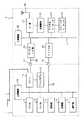
図1は、無線通信装置の要部構成を示したブロック図である。この装置は、無線通信の親機として機能するとともに、通信回線として電話回線Lを接続し、この回線Lを通じた画像データ通信(ファクシミリ通信)と、音声通話とを可能とする。なお、これらの通信、通話は、この装置を介して、無線通信により子機側でも可能になっている。
【0010】
図において、1は電話回線Lを接続する画像通信部、2はこの画像通信部1に接続される無線通信部である。ここでは、画像通信部1は、既存のファクシミリ装置で構成されているが、これには限定されず、子機による通信、通話の中継機能を果たすだけのものであってもよく、この場合は、ファクシミリ装置からスキャナ機能とプリンタ機能を取り除くことができる。また、一方の無線通信部2は、通信基板として構成され、画像通信部1にオプションとして接続できるようになっている。
【0011】
画像通信部1と無線通信部2は、電話端子T1と画像端子T2とで接続されている。ここに、電話端子T1は、従来、ファクシミリ装置(1)が外付け電話機を接続するために設けている端子であり、モジュラジャックを差し込み、コネクタ接続するだけで、電話機による電話回線Lを通じた通話を可能とするものである。このように、無線通信部2は、既存の電話端子T1を用いて、画像通信部1に接続できるので、画像通信部1の構成が複雑にならずに済む。
【0012】
画像通信部1において、10はCPU等で制御手段を構成し、バス18で接続された各部を制御する主制御部、11は電話回線Lの閉結、開放などを制御するNCU、12は電話回線Lを通じてファクシミリ通信するため、信号を変調、復調するFAXモデム、13は主制御部10が各部を制御するために必要なソフトウェアプログラムなどを記憶したROM、14は必要なデータを記憶するために使用されるRAM、15はファクシミリ送信する画像を原稿から読み取る読取部、16は受信した画像データを所定の記録紙に記録(印字出力)する記録部、17はテンキーや発信キー等で構成され、各種操作や電話番号等を入力するための操作部である。なお、この操作部17には、入力された電話番号等を表示する表示手段を含んでいる。
【0013】
一方、無線通信部2において、20はCPU等で構成され、バス27で接続された各部を制御する主制御部、21はアンテナA2を接続して、アンテナA2から子機に信号を送信するとともに、子機から信号を受信するRF部、22は子機に送信するデータを、例えばπ/4シフトQPSK(4相位相変調)方式により変調する一方、子機から受信したデータを同方式により復調する変復調部、23はTDMA(時分割多元接続)方式に適合したデータの作成、及び子機から受信したデータから必要なデータを抽出するチャネルコーデック、24は子機に送信するデータをADPCM(適応差分パルス符号変調)方式により符号化し、子機からの受信データを同方式により復号するADPCMコーデック、25は音声通話のため、アナログ信号を入出力するためのアナログI/F(インタフェース)部、26は記憶手段を構成し、通信する画像データ(デジタルデータ)の他、画像通信部1との間で制御データをやり取りするため、双方からのデータ入出力を可能とするデュアルポートRAM(以下、「DPRAM」という。)である。
【0014】
画像通信部1の主制御部10は、無線通信部2のDPRAM26を、バス18を介して直接アクセスできるようになっており、また、画像通信部1において音声通信手段を構成するNCU11は、無線通信部2のアナログI/F部25を、アナログ信号ライン28を介して接続する。
画像通信部1は、子機から無線通信部2を介して行われる、電話回線Lに対する画像通信時には、バス18を介してDPRAM26をアクセスし、このDPRAM26を介在させて画像データを送受する一方、通話時には、アナログI/F部25からアナログ信号である音声信号を、アナログ信号ライン28、電話端子T1を介して送受することにより、NCU11から電話回線Lを通じ、通話を可能とする。
【0015】
このように、画像通信部1(ファクシミリ装置)は、無線通信部2(無線通信基板)を接続することにより、無線通信による音声通信と画像通信とを実現する、PIAFS(PHS Internet Access Forum Standard)に容易に対応できる。
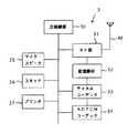
次に、無線通信の子機の構成について、図2のブロック図とともに説明する。ここには、子機3として、音声通話を可能とする無線式のファクシミリ装置の構成を示している。
【0016】
図において、30はCPU等で構成され、以下の各部を制御する主制御部、31はアンテナA3を接続して、アンテナA3から信号を親機側(無線通信部2)に送信するとともに、親機側から信号を受信するRF部、32は親機側に送信するデータを変調する一方、親機側から受信したデータを復調する変復調部、33はTDMA方式に適合したデータの作成、及び親機側から受信したデータからの必要なデータの抽出を行うチャネルコーデック、34は親機側に送信するデータをADPCM方式により符号化し、親機側からの受信データを同方式により復号するADPCMコーデック、35は通話機能を果たすマイク及びスピーカ、36は画像を読み取るスキャナ、37は受信した画像データを記録紙に印字出力するプリンタである。また、子機3には、図示していないが、テンキーや発信キー等で構成され、各種操作や電話番号等を入力するための操作手段なども備える。
【0017】
なお、子機3としては、図示したような構成の装置以外に、無線通信機能を備えたスキャナやプリンタ、PHSなどを接続して無線通信を実現するパーソナルコンピュータなどでも構成できる。したがって、子機3では、画像通信部1を、電話回線Lを介した通信を行うための中継装置(モデム)として機能させる以外に、読取部15を作動させてスキャナとして機能させたり、記録部16を作動させてプリンタとして機能させたりすることもできる。
【0018】
子機3からファクシミリ送信する場合は、主制御部30は、スキャナ36から読み取った画像データを基に、チャネルコーデック33で送信データを作成し、変復調部32で変調して、RF部31からアンテナA3を通じて親機側に送出する。すると、無線通信の親機となる無線通信部2は、この画像データをアンテナA2を通じてRF部21で受信し、変復調部22で復調し、チャネルコーデック23でデータを抽出して、DPRAM26に格納する。その後、画像通信部1は、DPRAM26をアクセスして画像データを取り出し、この画像データを、FAXモデム12、NCU11を介して、電話回線Lに送出する。一方、ファクシミリ受信の場合は、画像データはファクシミリ送信とは逆のルートを経由することになり、子機3では画像データを受信すると、プリンタ37からその画像を印字出力する。
【0019】
また、子機3が電話回線Lを通じて通話する場合は、主制御部30は、マイク(35)から入力された音声をADPCMコーデック34によって符号化し、チャネルコーデック33で送信データを作成し、変復調部32で変調して、RF部31からアンテナA3を通じて親機側に送出する。また、逆のルートを経由して音声信号を受信するときは、ADPCMコーデック34によって復号した音声をスピーカ(35)から出力する。
【0020】
無線通信部2は、子機3からの音声信号を、アンテナA2を通じてRF部21で受信したときは、変復調部22で復調し、チャネルコーデック23でデータを抽出し、ADPCMコーデック24で復号した後、アナログI/F部25からアナログ信号ライン28を介して出力し、画像通信部1では、その音声信号をNCU11によって接続された電話回線Lを通じて送出する。電話回線Lを通じて音声信号を受けたときには、画像通信部1と無線通信部2内の逆のルートを経由することによって、子機3に対して音声信号が送出され、子機3による通話を実現する。
【0021】
次に、図3に、本発明装置の画像通信部1と無線通信部2の動作をフローチャート(100〜107)で示す。
通話であるときは、画像通信部1は、電話回線LとNCU11、アナログ信号ライン28を接続し、無線通信部2はアナログI/F部25によって音声信号を入出力するとともに、子機3に対して音声信号を無線で通信する(100のYes,101,102)。
【0022】
一方、画像通信であり、電話回線Lを通じて画像データを送信するときは、無線通信部2は子機3からのデータを受け、そのデータをDPRAM26に格納する。画像通信部1はDPRAM26から画像データを読み出し、その画像データをFAXモデム12で変調した後、NCU11を介して電話回線Lに出力する(100のNo,103のYes,104,105)。
【0023】
また、電話回線Lを通じて画像データを受信するときは、画像通信部1は、電話回線Lから受信した画像データの信号を、FAXモデム12で復調した後、DPRAM26に格納する。無線通信部2は、DPRAM26から画像データを読み出して、子機3に対して送出する(100のNo,103のNo,106,107)。
【0024】
【発明の効果】
以上の説明からも理解できるように、本発明の請求項1に記載の無線通信装置は、画像データを無線通信する無線通信部を、通信回線を接続する画像通信部に接続すれば、画像通信部が、無線通信部の記憶手段を直接アクセスすることにより、画像データをやり取りし、この装置を介した子機での無線の画像通信を可能にする。したがって、既存の画像通信部に対して簡易な構成で無線通信部を接続できる。
【0025】
請求項2では、画像通信部は、無線通信部をアナログ信号ラインを介して接続し、音声信号は、このアナログ信号ラインを通じて送受され、画像データとは別の経路でやりとりされるので、画像通信部では、複雑な制御が必要なく、処理負担が小さくなってその構成を簡易にできる。
【図面の簡単な説明】
【図1】本発明の無線通信装置の要部構成の一例を示すブロック図である。
【図2】子機の要部構成の一例を示すブロック図である。
【図3】図1に示した無線通信装置の基本動作を示すフローチャートである。
【符号の説明】
1・・・画像通信部
10・・・主制御部
11・・・NCU
18・・・バス
2・・・無線通信部
20・・・主制御部
25・・・アナログI/F部
26・・・DPRAM
27・・・バス
28・・・アナログ信号ライン
T1・・・電話端子
T2・・・画像端子
L・・・通信回線(電話回線)
3・・・子機[0001]
BACKGROUND OF THE INVENTION
The present invention relates to a wireless communication apparatus that communicates image data for wireless communication via a communication line.
[0002]
[Prior art]
Conventionally, cordless telephones in which the master unit and slave units are wirelessly connected as wireless communication devices have been widely used in ordinary homes. Recently, however, the slave units are used as facsimile devices while communicating with the master unit. A system connected to a line has been developed. According to this system, the facsimile apparatus only needs to have an image reading function (scanner function) and an image recording function (printer function). The installation location can be moved freely without worrying about wiring.
[0003]
[Problems to be solved by the invention]
However, the base unit side of the wireless communication apparatus in the case of the above-described facsimile communication has a function of performing a facsimile communication by connecting a communication line (telephone line) in advance and a function of performing a wireless communication with a facsimile apparatus as a slave unit. I had to have. In addition, when a voice communication device such as PHS which is a slave unit can also make a call via the master unit, the configuration and control of the master unit are complicated.
[0004]
The present invention has been made in view of such circumstances, and has a configuration in which a wireless communication unit can be easily connected to an image communication unit that connects a communication line so that communication control is not complicated. An object is to provide a wireless communication device.
[0005]
[Means for Solving the Problems]
In order to achieve the above object, a wireless communication apparatus according to
That is, when image data is transmitted from the slave unit via this device, the image communication unit sends the image data wirelessly received by the wireless communication unit to the communication line, while the slave unit transmits image data from the outside to this device. When the image data is received via the wireless communication unit, the image communication unit wirelessly transmits the image data received through the communication line to the slave unit.
[0006]
Here, the wireless communication unit includes a board (option board) provided with a dual port RAM or the like as storage means. The image communication unit accesses the dual port RAM of the connected board and exchanges image data to be communicated via the communication line.
[0007]
According to a second aspect of the present invention, the image communication unit further includes a voice communication unit that connects the wireless communication unit through thetelephone terminal and the analog signal line, and the voice communication unit passes through the analog signal line and the communication line by the wireless communication unit. Control voice communication.
[0009]
DETAILED DESCRIPTION OF THE INVENTION
Embodiments of the present invention will be described below with reference to the drawings.
FIG. 1 is a block diagram showing a main configuration of a wireless communication apparatus. This apparatus functions as a base unit for wireless communication, and connects a telephone line L as a communication line, and enables image data communication (facsimile communication) and voice call through the line L. Note that these communications and calls can also be made on the slave unit side by wireless communication via this device.
[0010]
In the figure, 1 is an image communication unit for connecting a telephone line L, and 2 is a wireless communication unit connected to the
[0011]
The
[0012]
In the
[0013]
On the other hand, in the
[0014]
The main control unit 10 of the
The
[0015]
As described above, the image communication unit 1 (facsimile apparatus) realizes voice communication and image communication by wireless communication by connecting the wireless communication unit 2 (wireless communication board), and PIAFS (PHS Internet Access Forum Standard). Can be easily accommodated.
Next, the configuration of the wireless communication slave unit will be described with reference to the block diagram of FIG. Here, a configuration of a wireless facsimile machine that enables voice communication as the
[0016]
In the figure, 30 is composed of a CPU and the like, and is a main control unit for controlling the following units, 31 is connected to an antenna A3 and transmits a signal from the antenna A3 to the master unit side (wireless communication unit 2). An RF unit for receiving a signal from the machine side, 32 modulates data to be transmitted to the parent machine side, while a modem unit for demodulating data received from the parent machine side, 33 creates data suitable for the TDMA system, and A channel codec that extracts necessary data from data received from the machine side, and an ADPCM codec that encodes data to be transmitted to the parent machine side by the ADPCM system and decodes received data from the parent machine side by the same system,
[0017]
In addition to the device having the configuration shown in the figure, the
[0018]
When performing facsimile transmission from the
[0019]
When the
[0020]
When the RF signal is received by the
[0021]
Next, FIG. 3 is a flowchart (100 to 107) showing operations of the
In the case of a call, the
[0022]
On the other hand, when the image communication is performed and image data is transmitted through the telephone line L, the
[0023]
Further, when receiving image data through the telephone line L, the
[0024]
【The invention's effect】
As can be understood from the above description, the wireless communication apparatus according to
[0025]
According to the second aspect of the present invention, the image communication unit connects the wireless communication unit via the analog signal line, and the audio signal is transmitted / received through the analog signal line and is exchanged through a path different from the image data. In the unit, complicated control is not required, and the processing load is reduced, and the configuration can be simplified.
[Brief description of the drawings]
FIG. 1 is a block diagram illustrating an example of a main configuration of a wireless communication apparatus according to the present invention.
FIG. 2 is a block diagram showing an example of a configuration of a main part of a slave unit.
3 is a flowchart showing the basic operation of the wireless communication apparatus shown in FIG.
[Explanation of symbols]
DESCRIPTION OF
18 ...
27 ...
3 ... handset
Claims (2)
Translated fromJapaneseこの画像通信部に、上記電話端子と上記画像端子とを通じて、画像データを無線通信する無線通信部を接続した構成とされ、
上記無線通信部には、画像データを記憶する記憶手段を備える一方、
上記画像通信部には、上記無線通信部の記憶手段を、バスを通じて直接アクセスする制御手段を備えている無線通信装置。The image communication unit for communicating image data through a communication line such as a telephone line has a telephone terminal for connecting an external telephone and an image terminal for transmitting and receiving image data to and from the wireless communication unit. ,
The image communication unit is connected to a wireless communication unit that wirelessly communicates image data through the telephone terminal and the image terminal.
While the wireless communication unit includes storage means for storing image data,
The wireless communication apparatus, wherein the image communication unit includes a control unit that directly accesses the storage unit of the wireless communication unit through a bus.
上記音声通信手段は、上記無線通信部による上記アナログ信号ライン及び上記通信回線を通じた音声通信を制御する、請求項1に記載の無線通信装置。The image communication unit further includes voice communication means for connecting the wireless communication unit through thetelephone terminal and an analog signal line ,
The wireless communication apparatus according to claim 1, wherein the voice communication unit controls voice communication through the analog signal line and the communication line by the wireless communication unit.
Priority Applications (1)
| Application Number | Priority Date | Filing Date | Title |
|---|---|---|---|
| JP04954798AJP3815029B2 (en) | 1998-03-02 | 1998-03-02 | Wireless communication device |
Applications Claiming Priority (1)
| Application Number | Priority Date | Filing Date | Title |
|---|---|---|---|
| JP04954798AJP3815029B2 (en) | 1998-03-02 | 1998-03-02 | Wireless communication device |
Publications (2)
| Publication Number | Publication Date |
|---|---|
| JPH11252658A JPH11252658A (en) | 1999-09-17 |
| JP3815029B2true JP3815029B2 (en) | 2006-08-30 |
Family
ID=12834232
Family Applications (1)
| Application Number | Title | Priority Date | Filing Date |
|---|---|---|---|
| JP04954798AExpired - Fee RelatedJP3815029B2 (en) | 1998-03-02 | 1998-03-02 | Wireless communication device |
Country Status (1)
| Country | Link |
|---|---|
| JP (1) | JP3815029B2 (en) |
Families Citing this family (2)
| Publication number | Priority date | Publication date | Assignee | Title |
|---|---|---|---|---|
| US7099958B2 (en) | 2000-08-15 | 2006-08-29 | Fujitsu Limited | System for designing and performing web application |
| JP5019965B2 (en)* | 2007-06-15 | 2012-09-05 | 株式会社リコー | Image processing device, expansion board, and electrical equipment |
- 1998
- 1998-03-02JPJP04954798Apatent/JP3815029B2/ennot_activeExpired - Fee Related
Also Published As
| Publication number | Publication date |
|---|---|
| JPH11252658A (en) | 1999-09-17 |
Similar Documents
| Publication | Publication Date | Title |
|---|---|---|
| US5778314A (en) | Speech message recording and reproducing method and apparatus | |
| JPH0646123Y2 (en) | Facsimile transmitter / receiver | |
| JP3815029B2 (en) | Wireless communication device | |
| EP0416598A2 (en) | Facsimile apparatus | |
| JP3646353B2 (en) | Digital mobile phone device and facsimile device | |
| JPH0345072A (en) | Facsimile equipment | |
| JPS6348063A (en) | fax machine | |
| JPH0345070A (en) | facsimile machine | |
| JP3426858B2 (en) | Cordless telephone | |
| KR0149714B1 (en) | Transmission device of voice and image | |
| JPH1056674A (en) | Digital information transmission system | |
| JPH05110718A (en) | modem | |
| JP3142432B2 (en) | Data communication device, mobile communication device, information processing device | |
| JP2615105B2 (en) | Data transmission equipment | |
| JPH0456454A (en) | Cordless facsimile equipment | |
| JPH04329050A (en) | Registration information copying machine for simple dialing function | |
| JPH06233063A (en) | Facsimile equipment | |
| JP3475108B2 (en) | Telephones, cordless telephone system handsets, mobile phones | |
| JP3061982B2 (en) | Digital portable radio telephone equipment | |
| JPH0345066A (en) | facsimile machine | |
| JPH0491552A (en) | Facsimile equipment provided with telephoning function | |
| JPH0345071A (en) | Facsimile equipment | |
| JPH05284261A (en) | Facsimile equipment | |
| JPH05110733A (en) | Facsimile equipment | |
| JPH10173803A (en) | Facsimile machine |
Legal Events
| Date | Code | Title | Description |
|---|---|---|---|
| A621 | Written request for application examination | Free format text:JAPANESE INTERMEDIATE CODE: A621 Effective date:20040419 | |
| A977 | Report on retrieval | Free format text:JAPANESE INTERMEDIATE CODE: A971007 Effective date:20050830 | |
| A131 | Notification of reasons for refusal | Free format text:JAPANESE INTERMEDIATE CODE: A131 Effective date:20050906 | |
| A521 | Written amendment | Free format text:JAPANESE INTERMEDIATE CODE: A523 Effective date:20051104 | |
| TRDD | Decision of grant or rejection written | ||
| A01 | Written decision to grant a patent or to grant a registration (utility model) | Free format text:JAPANESE INTERMEDIATE CODE: A01 Effective date:20060516 | |
| A61 | First payment of annual fees (during grant procedure) | Free format text:JAPANESE INTERMEDIATE CODE: A61 Effective date:20060529 | |
| R150 | Certificate of patent or registration of utility model | Free format text:JAPANESE INTERMEDIATE CODE: R150 | |
| FPAY | Renewal fee payment (event date is renewal date of database) | Free format text:PAYMENT UNTIL: 20090616 Year of fee payment:3 | |
| FPAY | Renewal fee payment (event date is renewal date of database) | Free format text:PAYMENT UNTIL: 20120616 Year of fee payment:6 | |
| FPAY | Renewal fee payment (event date is renewal date of database) | Free format text:PAYMENT UNTIL: 20130616 Year of fee payment:7 | |
| FPAY | Renewal fee payment (event date is renewal date of database) | Free format text:PAYMENT UNTIL: 20130616 Year of fee payment:7 | |
| FPAY | Renewal fee payment (event date is renewal date of database) | Free format text:PAYMENT UNTIL: 20140616 Year of fee payment:8 | |
| LAPS | Cancellation because of no payment of annual fees |