JP3813006B2 - Titration control method - Google Patents
Titration control methodDownload PDFInfo
- Publication number
- JP3813006B2 JP3813006B2JP28284497AJP28284497AJP3813006B2JP 3813006 B2JP3813006 B2JP 3813006B2JP 28284497 AJP28284497 AJP 28284497AJP 28284497 AJP28284497 AJP 28284497AJP 3813006 B2JP3813006 B2JP 3813006B2
- Authority
- JP
- Japan
- Prior art keywords
- titration
- reagent
- chemical
- physical quantity
- change
- Prior art date
- Legal status (The legal status is an assumption and is not a legal conclusion. Google has not performed a legal analysis and makes no representation as to the accuracy of the status listed.)
- Expired - Fee Related
Links
- 238000004448titrationMethods0.000titleclaimsdescription137
- 238000000034methodMethods0.000titleclaimsdescription24
- 239000003153chemical reaction reagentSubstances0.000claimsdescription43
- 239000007788liquidSubstances0.000claimsdescription24
- 239000000126substanceSubstances0.000claimsdescription22
- 239000012085test solutionSubstances0.000claimsdescription20
- 238000006386neutralization reactionMethods0.000claimsdescription10
- 238000002835absorbanceMethods0.000claimsdescription3
- 239000013522chelantSubstances0.000claimsdescription3
- 230000033116oxidation-reduction processEffects0.000claimsdescription3
- 238000001556precipitationMethods0.000claimsdescription3
- HEMHJVSKTPXQMS-UHFFFAOYSA-MSodium hydroxideChemical compound[OH-].[Na+]HEMHJVSKTPXQMS-UHFFFAOYSA-M0.000description6
- QAOWNCQODCNURD-UHFFFAOYSA-NSulfuric acidChemical compoundOS(O)(=O)=OQAOWNCQODCNURD-UHFFFAOYSA-N0.000description4
- 230000000052comparative effectEffects0.000description4
- 238000005259measurementMethods0.000description4
- 238000001514detection methodMethods0.000description3
- 230000000694effectsEffects0.000description3
- 238000006243chemical reactionMethods0.000description2
- 239000003208petroleumSubstances0.000description2
- 238000007747platingMethods0.000description2
- 239000000243solutionSubstances0.000description2
- 238000003756stirringMethods0.000description2
- XLYOFNOQVPJJNP-UHFFFAOYSA-NwaterSubstancesOXLYOFNOQVPJJNP-UHFFFAOYSA-N0.000description2
- 238000004458analytical methodMethods0.000description1
- 230000003247decreasing effectEffects0.000description1
- 230000003111delayed effectEffects0.000description1
- 238000010586diagramMethods0.000description1
- 238000005342ion exchangeMethods0.000description1
- 239000000463materialSubstances0.000description1
- 230000035484reaction timeEffects0.000description1
- 238000004904shorteningMethods0.000description1
Images

Landscapes
- Investigating Or Analyzing Non-Biological Materials By The Use Of Chemical Means (AREA)
- Automatic Analysis And Handling Materials Therefor (AREA)
- Investigating Or Analyzing Materials By The Use Of Electric Means (AREA)
Description
Translated fromJapanese【0001】
【発明の属する技術分野】
本発明は、一般に、食品の酸度、塩分測定、メッキ液の濃度管理、石油の中和価測定などにて利用可能な滴定制御方法に関し、特に被検液の反応速度に応じた滴定を自動的に行うことのできる滴定制御方法に関するものである。
【0002】
【従来の技術】
従来、被検液に滴定試薬を少量ずつ滴加し、被検液の濃度を測定する滴定は、化学成分の濃度を測定するために有効で、汎用性の高い分析方法であり、食品の酸度、塩分測定、メッキ液の濃度管理、石油の中和価測定など様々の産業分野で利用されている。
【0003】
滴定を行う場合、被検液に対して滴定試薬を滴加し、被検液の化学量又は物理量変化をセンサにより検出し、滴定の終点を自動的に判別する自動滴定装置が実用化されている。このような自動滴定装置で滴定の終点を判断する場合、
(1)滴定試薬の滴加量に対して被検液の化学量又は物理量変化が直線的に変化せず、特に滴定の終点付近において変化量が大きくなる場合があること、
(2)被検液の化学量又は物理量変化を検出するセンサのレスポンスが実際の変化に対して遅れる場合があること、
(3)滴定の種類によっては化学反応の反応時間が異なること、
(4)被検液と滴定試薬を混合するためにある程度時間を要すること、
などの問題があり、滴定試薬を一定の速度で滴加すると、終点の検出を見間違うことがあった。
【0004】
この場合、滴定試薬の1回の滴加量を極力少なくしたり、滴定試薬の滴加間隔を十分にとることにより終点の検出が確実に行えるが、滴定が終了するまでの時間が長くなり、迅速性を損なう要因となっていた。
【0005】
【発明が解決しようとする課題】
そこで、上記問題を解決するために、被検液の化学量又は物理量変化が大きい場合には滴定試薬の滴加量を少なくし、その変化量が小さい場合には滴定試薬の滴加量を大きくするというフィードバック制御により、なるべく滴定時間を短くする方法や、濃度がある程度分かっている被検液の場合には予め予備滴加してから滴定を行う方法などを採用し、できるだけ滴定時間を短くするための工夫が成されてきたが、それだけでは不十分な場合があった。又、これらの場合においてもセンサのレスポンスなどを考慮し、滴定試薬を滴加してから次の滴加を行うまでの間隔をある程度余裕を持って設定する必要があり、滴定時間を長くする要因になっていた。
【0006】
従って、本発明の目的は、被検液に滴定試薬を滴加し、被検液の化学量又は物理量の変化をセンサにより検出し、その変化量に応じて常に適切な間隔にて滴定試薬を滴加し、滴定時間の短縮を達成することができ、更には、終点付近で変化が大きくなった場合でも、終点の検出を確実におこない、高精度にて滴定を行うことのできる滴定制御方法を提供することである。
【0007】
【課題を解決するための手段】
上記目的は本発明に係る滴定制御方法にて達成される。要約すれば、本発明は、被検液に滴定試薬を少量ずつ滴加し、被検液の化学量又は物理量の変化をセンサにて測定する滴定における制御方法であって、滴定試薬を滴加して所定の待ち時間経過した後の被検液の化学量又は物理量変化の大きさに応じて、次に滴定試薬を滴加した後の前記センサによる被検液の化学量又は物理量検出のための待ち時間の大きさを制御するようにしたことを特徴とする滴定制御方法である。
【0008】
本発明の一実施態様によると、前記被検液の化学量又は物理量変化が大きい場合には、次に滴定試薬を滴加した後の被検液の化学量又は物理量検出のための待ち時間を大きくし、前記被検液の化学量又は物理量変化が小さい場合には前記待ち時間を小さくする。
【0009】
本発明によれば、前記滴定は、中和滴定、非水中和滴定、酸化還元滴定、沈殿滴定、キレート滴定又は温度滴定であり、前記滴定に使用するセンサは、pH電極、ORP電極、電導度電極、イオン電極、吸光度センサ又は温度センサであり、前記被検液の化学量又は物理量は、液の電気的な量、呈色又は温度である。
【0010】
【発明の実施の形態】
以下、本発明に係る滴定制御方法を図面に則して更に詳しく説明する。
【0011】
実施例1
本発明の滴定制御方法は、中和滴定、非水中和滴定、酸化還元滴定、沈殿滴定、キレート滴定、温度滴定などのあらゆる滴定に適用することができ、検出に用いるセンサとしては、pH電極、ORP電極、電導度電極、イオン電極、吸光度センサ、温度センサなど、滴定に使用できる全てのセンサを使用することができる。
【0012】
本実施例では、本発明の滴定制御方法を、センサとしてpH電極を用いた硫酸の水酸化ナトリウムによる中和滴定に適用するものとして説明する。
【0013】
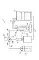
図1に、本発明を実施する自動滴定装置の概略構成を示す。自動滴定装置1は、被検液Lを収容する被検液容器2を備え、この容器2内にはpH電極3と比較電極4が挿入され、各電極3、4は、それぞれリード線5、6にて自動滴定装置本体7に接続されている。又、容器2内には、撹拌子8が配置され、スターラ9により回転可能とされる。
【0014】
又、自動滴定装置1は、更に、シリンジ10及びこのシリンジ10に嵌合したピストン11を備え、ピストン11は、ピストン11に連結された駆動装置12によりシリンジ10内を往復動可能とされる。駆動装置12は、装置本体7にケーブル14にて接続され、装置本体7からの信号により駆動制御される。前記シリンジ10は、滴定試薬Aを収容した滴定試薬容器15に、導入管16、3方コックの第1の弁13a及び第2の弁13b、更に、導入管17を介して接続されている。従って、駆動装置12によりピストン11を駆動することにより、容器15内の滴定試薬Aは、導入管16、3方コックの第1の弁13a及び第2の弁13b、そして、導入管17を介してシリンジ10内へと導入される。又、前記3方コック13の第3の弁13cは、導入管18を介して、容器2内に挿入されたノズル19に接続されている。
【0015】
次に図2を参照して、上記構成の自動滴定装置1を使用して、本発明の制御方法に従って中和滴定を行う場合について説明する。
【0016】
本実施例では、先ず、滴定試薬容器15に滴定試薬Aとして0.1N水酸化ナトリウムを入れ、3方コック13を切り換えて弁13a、13bを開とし、滴定試薬容器15とシリンジ10とを導入管16、17にて接続する。次いで、駆動装置12を付勢し、ピストン11を図面にて下方へと動かし、滴定試薬Aをシリンジ10内に導入する。滴定試薬導入後、3方コック13を切り換えて、弁13b、13cを開とし、シリンジ10とノズル19とを導入管17、18を介して接続する。次いで、駆動装置12でピストン11を図面にて上方へと駆動して、シリンジ10の上方に溜まった空気をノズル19から捨て、シリンジ10、導入管17、18及びノズル19を滴定試薬で満たす。
【0017】
次いで、被検液容器2に被検液Lとして、本実施例では約0.1Nの硫酸をホールピペットで10ml正確に秤量して入れ、イオン交換水約50mlを加えた。容器2内に配置した撹拌子8をスターラ9により回転し、被検液Lとイオン交換水とを良く撹拌する。スターラ9は滴定の間常に回転させておく。この状態で、先ず、pH電極3と比較電極4からの信号に基づき装置本体7で、被検液Lの電気的な量、本実施例では電位E1を検出し、この電位を保存する(ステップ1、2)。
【0018】
電位E1を検出した後、駆動装置12によりピストン11を上方に動かして、滴定試薬Aを所定量M、容器2内へと滴加する(ステップ3)。滴定試薬Aの滴加量Mも電位変化により制御することができるが、本発明の効果を明確にするために、本実施例では、1回の滴加量Mを0.1mlに固定して滴定を行った。待ち時間TINT を所定の時間T1に設定し(ステップ4)、滴定試薬滴加T1後の被検液電位E2を検出し、この電位を保存する(ステップ5、6、7)。
【0019】
次いで、(前回保存した電位E1−今回保存した電位E2)の絶対値ESと、予め設定された電位変化ES1とを比較し、(E1−E2)の絶対値ESが電位変化ES1に対して、ES<ES1の場合には、前にステップ4で設定した待ち時間T1を所定時間△T、例えば1秒短くする(ステップ9)。逆に、ES≧ES1の場合には、待ち時間T1を所定時間△T、例えば1秒長くする(ステップ10)。
【0020】
このとき、微分値(滴定試薬滴加毎の電位変化量)から滴定の終点を判断し(ステップ11)、終点と判断すると、滴定作業を終了する。もし、終点でないと判断したときは、上記ステップ3に戻り、再度滴定試薬Aを所定量Mだけ被検液容器2内へと滴加する(ステップ3)。待ち時間TINT は、上記ステップ9、10に基づき、T1−△Tか、或いはT1+△Tに再設定されており(ステップ4)、今回は、滴定試薬滴加後T1−△T或いはT1+△T経過後の被検液電位E3を検出し、この電位を保存する(ステップ5、6、7)。
【0021】
次いで、(前回保存した電位E2−今回保存した電位E3)の絶対値ESと、予め設定された電位変化ES1とを比較し(ステップ8)、(E2−E3)の絶対値ESが電位変化ES1に対して、ES<ES1の場合には、待ち時間T1−△T或いはT1+△Tに、所定時間△Tだけ加えるか或いは引くことにより(ステップ9、10)、前にステップ4にて設定した待ち時間TINT を設定し直す。
【0022】
続いて、前回と同様に、滴定の終点を判断し、滴定を終了するか、或いは、ステップ3に戻って、上記手順に従って滴定作業を続ける。
【0023】
このようにして滴定を行うと、電位変化ESが大きい場合には、待ち時間TINT を長くし、電位変化ESが小さい場合には、待ち時間TINT を短くすることができるために、終点付近で変化量が大きくなっても、滴定試薬を入れすぎたりすることがなくなり、常に最短の待ち時間で滴定を行うことができ、滴定終了までの時間を短くすることができる。
【0024】
本実施例では、これに限定されるものではないが、上記待ち時間T1は3秒とし、調整時間△Tは1秒とし、電位ES1として2mVを設定することにより好結果を得ることができた。
【0025】
本実施例における滴定試薬Aの総滴加量と滴定時間を表1に示す。表1の値は、滴定を5回行ったときの平均値である。
【0026】
比較例1
実施例1で説明した自動滴定装置を使用し、待ち時間T1を3秒に固定して滴定した以外は、実施例1で説明したと同じ材料及び方法にて滴定を行った。
【0027】
比較例における滴定試薬Aの総滴加量と滴定時間を表1に示す。表1の値は、滴定を5回行ったときの平均値である。
【0028】
【表1】
表1にて、CV値(%)とは、測定値に対する繰り返し性を意味し、
CV値(%)=(標準偏差)÷(滴定試薬滴加量平均(ml))×100
にて求められる。
【0030】
表1に示す結果から、本発明に基づく実施例1と、比較例1とは、滴定試薬滴加量平均値はほぼ一致しており、又、繰り返し性を示すCV値は、共に0.25%以下であり、終点検出が正確に繰り返し性良く行われていることが分かった。一方、滴定時間は、実施例1では、2分13秒であるのに対して、比較例1では5分27秒と2倍以上の滴定時間を必要としており、本発明の滴定制御方法は、滴定時間を大幅に短縮し得ることが分かった。
【0031】
【発明の効果】
以上説明したように、本発明の滴定制御方法は、滴定試薬を滴加して所定の待ち時間経過した後の被検液の化学量又は物理量変化の大きさに応じて、次に滴定試薬を滴加した後のセンサによる被検液の化学量又は物理量検出のための待ち時間の大きさを制御する構成とされるので、
(1)被検液に滴定試薬を滴加し、被検液の化学量又は物理量の変化をセンサにより検出し、その変化量に応じて常に適切な間隔にて滴定試薬を滴加することができ、滴定時間の短縮を達成することができる。更には、
(2)終点付近で変化が大きくなった場合でも、終点の検出を確実におこない、高精度にて滴定を行うことができる。
という効果を奏し得る。
【図面の簡単な説明】
【図1】本発明の滴定制御方法を実施するための自動滴定装置の概略構成図である。
【図2】本発明の滴定制御方法の作動を説明するフロー図である。
【符号の説明】
1 自動滴定装置
2 被検液容器
3 pH電極
4 比較電極
7 装置本体
10 シリンジ
11 ピストン
12 駆動装置
13 3方コック
15 滴定試薬容器[0001]
BACKGROUND OF THE INVENTION
The present invention generally relates to a titration control method that can be used in food acidity, salinity measurement, plating solution concentration management, petroleum neutralization value measurement, etc., and in particular, titration according to the reaction rate of a test solution is automatically performed. The present invention relates to a titration control method that can be performed.
[0002]
[Prior art]
Traditionally, titration in which a titration reagent is added in small amounts to a test solution and the concentration of the test solution is measured is an effective and versatile analytical method for measuring the concentration of chemical components. It is used in various industrial fields such as salinity measurement, plating solution concentration control, and petroleum neutralization value measurement.
[0003]
When titration is performed, an automatic titration device that puts a titration reagent into a test solution, detects the chemical or physical quantity change of the test solution with a sensor, and automatically determines the end point of the titration has been put into practical use. Yes. When judging the end point of titration with such an automatic titrator,
(1) The change in the chemical or physical quantity of the test solution does not change linearly with respect to the titration reagent, and the change may be particularly large near the end point of the titration.
(2) The response of the sensor that detects a change in the chemical or physical quantity of the test solution may be delayed with respect to the actual change.
(3) Depending on the type of titration, the reaction time of the chemical reaction varies,
(4) It takes a certain amount of time to mix the test solution and the titration reagent,
When the titration reagent was added dropwise at a constant rate, the end point detection was sometimes mistaken.
[0004]
In this case, the end point can be reliably detected by reducing the titration amount of the titration reagent as much as possible or by taking a sufficient interval between the titration reagents, but the time until the titration ends is increased. It was a factor that impeded speediness.
[0005]
[Problems to be solved by the invention]
Therefore, in order to solve the above problem, the titration amount of the titration reagent is decreased when the chemical amount or physical quantity change of the test solution is large, and the titration amount of the titration reagent is increased when the change amount is small. By using feedback control, the titration time can be shortened as much as possible, and in the case of a test solution whose concentration is known to some extent, the titration time can be shortened as much as possible by adopting a method of performing preliminary titration in advance. Ingenuity has been made, but it was not enough. Also in these cases, it is necessary to set the interval between the addition of the titration reagent and the next addition with a certain margin in consideration of the response of the sensor. It was.
[0006]
Therefore, an object of the present invention is to add a titration reagent to a test solution, detect a change in the chemical or physical quantity of the test solution with a sensor, and always add a titration reagent at an appropriate interval according to the change amount. Titration control method that can achieve titration by shortening the titration time, and even if the change near the end point is large, the end point can be detected reliably and titration can be performed with high accuracy. Is to provide.
[0007]
[Means for Solving the Problems]
The above object is achieved by the titration control method according to the present invention. In summary, the present invention is a titration control method in which a titration reagent is added to a test solution little by little, and a change in the chemical amount or physical quantity of the test solution is measured by a sensor. In order to detect the chemical quantity or physical quantity of the test liquid by the sensor after the titration reagent is added dropwise according to the magnitude of the change in the chemical quantity or physical quantity of the test liquid after a predetermined waiting time has elapsed. The titration control method is characterized in that the waiting time is controlled.
[0008]
According to one embodiment of the present invention, when the change in the chemical quantity or physical quantity of the test liquid is large, the waiting time for detecting the chemical quantity or physical quantity of the test liquid after adding the titration reagent next is added. The waiting time is reduced when the chemical amount or physical quantity change of the test solution is small.
[0009]
According to the present invention, the titration is neutralization titration, non-aqueous neutralization titration, oxidation-reduction titration, precipitation titration, chelate titration, or temperature titration, and the sensors used for the titration are pH electrode, ORP electrode, conductivity It is an electrode, an ion electrode, an absorbance sensor, or a temperature sensor, and the chemical quantity or physical quantity of the test liquid is the electrical quantity, color, or temperature of the liquid.
[0010]
DETAILED DESCRIPTION OF THE INVENTION
Hereinafter, the titration control method according to the present invention will be described in more detail with reference to the drawings.
[0011]
Example 1
The titration control method of the present invention can be applied to all titrations such as neutralization titration, non-aqueous neutralization titration, oxidation-reduction titration, precipitation titration, chelate titration, temperature titration, and the sensor used for detection includes a pH electrode, Any sensor that can be used for titration, such as an ORP electrode, a conductivity electrode, an ion electrode, an absorbance sensor, and a temperature sensor can be used.
[0012]
In the present embodiment, the titration control method of the present invention will be described as applied to neutralization titration of sulfuric acid with sodium hydroxide using a pH electrode as a sensor.
[0013]
FIG. 1 shows a schematic configuration of an automatic titration apparatus for carrying out the present invention. The
[0014]
The
[0015]
Next, with reference to FIG. 2, the case where neutralization titration is performed according to the control method of the present invention using the
[0016]
In this embodiment, first, 0.1N sodium hydroxide is added as a titration reagent A to the
[0017]
Next, about 0.1 ml of sulfuric acid of about 0.1 N was accurately weighed with a whole pipette as a test liquid L in the test
[0018]
After detecting the potential E1, the
[0019]
Next, the absolute value ES of (previously stored potential E1-currently stored potential E2) is compared with a preset potential change ES1, and the absolute value ES of (E1-E2) is compared to the potential change ES1. If ES <ES1, the waiting time T1 previously set in
[0020]
At this time, the end point of the titration is determined from the differential value (the amount of potential change for each addition of the titration reagent) (step 11). If it is determined that it is not the end point, the process returns to step 3 above, and the titration reagent A is again dropped into the test
[0021]
Next, the absolute value ES of (previously stored potential E2−currently stored potential E3) is compared with a preset potential change ES1 (step 8), and the absolute value ES of (E2-E3) is the potential change ES1. On the other hand, if ES <ES1, previously set in
[0022]
Subsequently, as in the previous time, the end point of the titration is determined, and the titration is finished, or the process returns to step 3 and the titration operation is continued according to the above procedure.
[0023]
When titration is performed in this manner, the waiting time TINT can be lengthened when the potential change ES is large, and the waiting time TINT can be shortened when the potential change ES is small. Even if the amount of change becomes large, the titration reagent is not excessively added, the titration can always be performed with the shortest waiting time, and the time until the end of the titration can be shortened.
[0024]
In the present embodiment, although not limited to this, good results could be obtained by setting the waiting time T1 to 3 seconds, the adjustment time ΔT to 1 second, and setting the potential ES1 to 2 mV. .
[0025]
Table 1 shows the total titration amount and titration time of titration reagent A in this example. The values in Table 1 are average values when titration is performed 5 times.
[0026]
Comparative Example 1
Titration was performed using the same material and method as described in Example 1 except that the automatic titration apparatus described in Example 1 was used and titration was performed with the waiting time T1 fixed at 3 seconds.
[0027]
Table 1 shows the total titration amount and titration time of the titration reagent A in the comparative example. The values in Table 1 are average values when titration is performed 5 times.
[0028]
[Table 1]
In Table 1, CV value (%) means repeatability with respect to the measured value,
CV value (%) = (standard deviation) ÷ (average titer addition amount (ml)) × 100
Is required.
[0030]
From the results shown in Table 1, Example 1 based on the present invention and Comparative Example 1 have substantially the same titration reagent titration amount, and both CV values indicating repeatability are 0.25. It was found that the end point detection was performed accurately and with good repeatability. On the other hand, the titration time in Example 1 is 2 minutes and 13 seconds, whereas in Comparative Example 1, the titration time is 5 minutes and 27 seconds, which is twice as long as the titration control method of the present invention. It has been found that the titration time can be significantly reduced.
[0031]
【The invention's effect】
As described above, according to the titration control method of the present invention, the titration reagent is added next according to the chemical amount or the physical quantity change of the test liquid after the titration reagent is added and a predetermined waiting time elapses. Since it is configured to control the waiting time for detecting the chemical quantity or physical quantity of the test liquid by the sensor after dropping,
(1) A titration reagent is added dropwise to a test solution, a change in the chemical or physical quantity of the test solution is detected by a sensor, and the titration reagent is always added at appropriate intervals according to the change amount. And a reduction in titration time can be achieved. Furthermore,
(2) Even when the change becomes large in the vicinity of the end point, the end point can be reliably detected and titration can be performed with high accuracy.
It can have the effect.
[Brief description of the drawings]
FIG. 1 is a schematic configuration diagram of an automatic titration apparatus for carrying out a titration control method of the present invention.
FIG. 2 is a flowchart for explaining the operation of the titration control method of the present invention.
[Explanation of symbols]
DESCRIPTION OF
Claims (3)
Translated fromJapanesePriority Applications (1)
| Application Number | Priority Date | Filing Date | Title |
|---|---|---|---|
| JP28284497AJP3813006B2 (en) | 1997-09-30 | 1997-09-30 | Titration control method |
Applications Claiming Priority (1)
| Application Number | Priority Date | Filing Date | Title |
|---|---|---|---|
| JP28284497AJP3813006B2 (en) | 1997-09-30 | 1997-09-30 | Titration control method |
Publications (2)
| Publication Number | Publication Date |
|---|---|
| JPH11108917A JPH11108917A (en) | 1999-04-23 |
| JP3813006B2true JP3813006B2 (en) | 2006-08-23 |
Family
ID=17657813
Family Applications (1)
| Application Number | Title | Priority Date | Filing Date |
|---|---|---|---|
| JP28284497AExpired - Fee RelatedJP3813006B2 (en) | 1997-09-30 | 1997-09-30 | Titration control method |
Country Status (1)
| Country | Link |
|---|---|
| JP (1) | JP3813006B2 (en) |
Families Citing this family (7)
| Publication number | Priority date | Publication date | Assignee | Title |
|---|---|---|---|---|
| JP4526905B2 (en)* | 2004-08-31 | 2010-08-18 | 京都電子工業株式会社 | Automatic titrator |
| JP5641646B2 (en) | 2010-11-22 | 2014-12-17 | 株式会社堀場製作所 | Titration device |
| CN107741469A (en)* | 2017-10-30 | 2018-02-27 | 王梓任 | An automatic titration chemical analysis system and its application method |
| JP7272970B2 (en)* | 2019-07-15 | 2023-05-12 | 王飛 | SPECTRAL POTENTIAL TEMPERATURE MULTI-DIMENSIONAL TITRATION ANALYZER AND ITS USAGE |
| CN113917072A (en)* | 2021-10-11 | 2022-01-11 | 聚光科技(杭州)股份有限公司 | Detection method based on reaction process control |
| CN115586297A (en)* | 2022-09-27 | 2023-01-10 | 内蒙古电力(集团)有限责任公司内蒙古电力科学研究院分公司 | Efficient and accurate component titration device |
| FR3145805B3 (en)* | 2023-02-09 | 2025-02-14 | Eurosmart | System for monitoring the evolution of at least one characteristic of a reactive mixture in a container. |
- 1997
- 1997-09-30JPJP28284497Apatent/JP3813006B2/ennot_activeExpired - Fee Related
Also Published As
| Publication number | Publication date |
|---|---|
| JPH11108917A (en) | 1999-04-23 |
Similar Documents
| Publication | Publication Date | Title |
|---|---|---|
| CN102012389B (en) | Quantitative analyzing method and quantitative analyzer using sensor | |
| JP5641646B2 (en) | Titration device | |
| US7349760B2 (en) | System and method for sensing and controlling the concentration of a chemical agent in a solution | |
| CN212228867U (en) | Online analysis intelligent management and control system for aluminum oxidation tank liquid | |
| CN111323531A (en) | Titration device and titration method for combining speed and speed in automatic titration process | |
| JP3813006B2 (en) | Titration control method | |
| US3717435A (en) | Process and apparatus for measuring and controlling the concentration of chemical compounds in solutions | |
| CN211955365U (en) | Automatic titration outfit that fast and slow combines among titration process | |
| US11885781B2 (en) | Titration apparatus and titration method | |
| US5186895A (en) | Method and apparatus for automatic analysis of fluid composition involving a time-dependent variation thereof | |
| US5518933A (en) | Method of analyzing washings for free acids and ions | |
| JP6126387B2 (en) | Electrolyte analyzer with double tube structure sample suction nozzle | |
| PT2409146E (en) | Method and device for determining a foreign substance content in a matrix | |
| JP2001296305A (en) | Automatic analyzer and automatic analysis method for sample solution | |
| JP4474628B2 (en) | Automatic titrator | |
| Borges et al. | Automatic stepwise potentiometric titration in a monosegmented flow system | |
| Almeida et al. | Automatic flow titrator based on a multicommutated unsegmented flow system for alkalinity monitoring in wastewaters | |
| US20210033562A1 (en) | Method for calibrating an analytical measuring device and measuring point for analyzing a process medium and for calibrating an analytical measuring device | |
| CN221765378U (en) | Automatic titration device with back titration function | |
| CA1132660A (en) | Method of measuring with redox- or ion-sensitive electrodes | |
| JPH0365489B2 (en) | ||
| JP2017151071A (en) | Titration control method and automatic titration apparatus | |
| JPH03137562A (en) | Automatic titrator | |
| Maciak et al. | Computerized technique in organic microelemental analysis: Part II. Automatic determination of sulfur in organic compounds | |
| CN210720302U (en) | Automatic titration detection device |
Legal Events
| Date | Code | Title | Description |
|---|---|---|---|
| A621 | Written request for application examination | Free format text:JAPANESE INTERMEDIATE CODE: A621 Effective date:20040910 | |
| A977 | Report on retrieval | Free format text:JAPANESE INTERMEDIATE CODE: A971007 Effective date:20060403 | |
| TRDD | Decision of grant or rejection written | ||
| A01 | Written decision to grant a patent or to grant a registration (utility model) | Free format text:JAPANESE INTERMEDIATE CODE: A01 Effective date:20060516 | |
| A61 | First payment of annual fees (during grant procedure) | Free format text:JAPANESE INTERMEDIATE CODE: A61 Effective date:20060530 | |
| R150 | Certificate of patent or registration of utility model | Free format text:JAPANESE INTERMEDIATE CODE: R150 | |
| FPAY | Renewal fee payment (event date is renewal date of database) | Free format text:PAYMENT UNTIL: 20090609 Year of fee payment:3 | |
| FPAY | Renewal fee payment (event date is renewal date of database) | Free format text:PAYMENT UNTIL: 20100609 Year of fee payment:4 | |
| FPAY | Renewal fee payment (event date is renewal date of database) | Free format text:PAYMENT UNTIL: 20100609 Year of fee payment:4 | |
| FPAY | Renewal fee payment (event date is renewal date of database) | Free format text:PAYMENT UNTIL: 20110609 Year of fee payment:5 | |
| FPAY | Renewal fee payment (event date is renewal date of database) | Free format text:PAYMENT UNTIL: 20110609 Year of fee payment:5 | |
| FPAY | Renewal fee payment (event date is renewal date of database) | Free format text:PAYMENT UNTIL: 20120609 Year of fee payment:6 | |
| FPAY | Renewal fee payment (event date is renewal date of database) | Free format text:PAYMENT UNTIL: 20130609 Year of fee payment:7 | |
| FPAY | Renewal fee payment (event date is renewal date of database) | Free format text:PAYMENT UNTIL: 20130609 Year of fee payment:7 | |
| R250 | Receipt of annual fees | Free format text:JAPANESE INTERMEDIATE CODE: R250 | |
| R250 | Receipt of annual fees | Free format text:JAPANESE INTERMEDIATE CODE: R250 | |
| R250 | Receipt of annual fees | Free format text:JAPANESE INTERMEDIATE CODE: R250 | |
| LAPS | Cancellation because of no payment of annual fees |