JP3811291B2 - Endoscope system - Google Patents
Endoscope systemDownload PDFInfo
- Publication number
- JP3811291B2 JP3811291B2JP18780398AJP18780398AJP3811291B2JP 3811291 B2JP3811291 B2JP 3811291B2JP 18780398 AJP18780398 AJP 18780398AJP 18780398 AJP18780398 AJP 18780398AJP 3811291 B2JP3811291 B2JP 3811291B2
- Authority
- JP
- Japan
- Prior art keywords
- endoscope
- module
- end portion
- treatment
- distal end
- Prior art date
- Legal status (The legal status is an assumption and is not a legal conclusion. Google has not performed a legal analysis and makes no representation as to the accuracy of the status listed.)
- Expired - Fee Related
Links
- 238000011282treatmentMethods0.000claimsdescription72
- 238000003780insertionMethods0.000claimsdescription32
- 230000037431insertionEffects0.000claimsdescription32
- 230000005540biological transmissionEffects0.000claimsdescription14
- 230000002093peripheral effectEffects0.000claimsdescription7
- 230000006978adaptationEffects0.000claimsdescription2
- 230000007423decreaseEffects0.000claimsdescription2
- 238000007689inspectionMethods0.000claimsdescription2
- 210000003750lower gastrointestinal tractAnatomy0.000description7
- 238000001574biopsyMethods0.000description5
- 239000012212insulatorSubstances0.000description5
- 238000011084recoveryMethods0.000description5
- 210000002438upper gastrointestinal tractAnatomy0.000description5
- 238000005286illuminationMethods0.000description3
- 238000004519manufacturing processMethods0.000description3
- 239000000463materialSubstances0.000description3
- 238000000034methodMethods0.000description3
- 210000000436anusAnatomy0.000description2
- 230000008878couplingEffects0.000description2
- 238000010168coupling processMethods0.000description2
- 238000005859coupling reactionMethods0.000description2
- 210000001198duodenumAnatomy0.000description2
- 230000000694effectsEffects0.000description2
- 229920001971elastomerPolymers0.000description2
- 239000000806elastomerSubstances0.000description2
- 238000012277endoscopic treatmentMethods0.000description2
- 210000003238esophagusAnatomy0.000description2
- 210000002429large intestineAnatomy0.000description2
- 239000011347resinSubstances0.000description2
- 229920005989resinPolymers0.000description2
- 210000002784stomachAnatomy0.000description2
- XLYOFNOQVPJJNP-UHFFFAOYSA-NwaterSubstancesOXLYOFNOQVPJJNP-UHFFFAOYSA-N0.000description2
- 230000009471actionEffects0.000description1
- 230000008859changeEffects0.000description1
- 238000004140cleaningMethods0.000description1
- 210000001072colonAnatomy0.000description1
- 239000003086colorantSubstances0.000description1
- 239000012141concentrateSubstances0.000description1
- 238000010586diagramMethods0.000description1
- 238000002674endoscopic surgeryMethods0.000description1
- 238000001839endoscopyMethods0.000description1
- 210000001035gastrointestinal tractAnatomy0.000description1
- 230000006872improvementEffects0.000description1
- 238000012986modificationMethods0.000description1
- 230000004048modificationEffects0.000description1
- 230000003287optical effectEffects0.000description1
- 238000004659sterilization and disinfectionMethods0.000description1
- 238000003860storageMethods0.000description1
- 230000001225therapeutic effectEffects0.000description1
- 210000001835visceraAnatomy0.000description1
- 238000005406washingMethods0.000description1
Images


Landscapes
- Surgical Instruments (AREA)
- Endoscopes (AREA)
Description
Translated fromJapanese【0001】
【発明の属する技術分野】
本発明は、内視鏡検査や内視鏡下手術において使用する内視鏡と、処置用の器材とを備えた内視鏡システムに関する。
【0002】
【従来の技術】
従来より、細長の挿入部を体腔内に挿入することにより、体腔内臓器などを観察したり、必要に応じて処置用チャンネル内に挿通した処置用の器材(処置具とも記載する)を用いて各種治療処置のできる医療用の内視鏡が広く利用されている。
【0003】
前記処置用の器材は、内視鏡の処置具用チャンネルの直径寸法が細径(3mm程度)で長尺(2m程度)な管腔内に挿通可能なように細長な構造になっている。このため、この細長な処置用の器材を内視鏡の処置用チャンネルに挿入する際、折れたり、破損したりするおそれがあるので、医療者は処置用の器材を処置用チャンネルに挿入するために細心の注意を払わなければならなかった。
【0004】
例えば、特開昭64−80335号公報には前記処置具の挿入時の破損を防止するため、処置用の器材に適度な弾力性を有する部材を用いたり、先端形状を滑らかにすることで挿入性を向上させるようにした内視鏡が示されている。
【0005】
また、経内視鏡的に処置を行う場合、内視鏡と処置具とが独立しているため、医療者は両手を用いて、複雑な内視鏡の操作と処置具の操作とを行ったり、介添え者を含む数人で内視鏡と処置具との操作を行わなければならないので、熟練した操作技術を必要にしていた。
【0006】
【発明が解決しようとする課題】
しかしながら、前記特開昭64−80335号公報に示されているように材料的な改善や形状を曲面にすることでは根本的な解決にならず、特に特殊な材料を使用する場合には材料の入手が困難なことや製造方法が複雑になって大量生産するには不向きで、処置具が高価になるなどといった問題があった。
【0007】
また、処置後に、細長な処置用の器材の洗滌、消毒などの後処理を行う際、洗滌し難く、後処理に時間がかかるという問題があるとともに、後処理後に処置具を保管、管理をする際、処置具が細長であるため保管スペースが大きくなるという問題があった。
【0008】
さらに、処置具の破損を防止し、内視鏡下での操作が容易で、小さなスペースで保管が可能な内視鏡システムを提供するために、複数の異なる内視鏡に複数種類の内視鏡用モジュールを使用する内視鏡システムも考えられるが、どの内視鏡用モジュールとどの内視鏡とが組合せ可能であるか否かを判断し難くなるという問題がある。
【0009】
本発明は上述した事情に鑑みてなされたものであり、どの内視鏡用モジュールとどの内視鏡とが同じグループであるか否かを、容易に判別することが可能な内視鏡システムを提供することを目的にしている。
【0010】
【課題を解決するための手段】
前記目的を達成するため本発明の一態様による内視鏡システムは、処置手段を備えた複数種類の内視鏡用モジュールと、この内視鏡用モジュールを内視鏡挿入部の先端部に着脱自在に取り付け可能な複数種類の内視鏡とを有する内視鏡システムにおいて、前記内視鏡用モジュールは、内視鏡先端部を外嵌配置する内部空間部を有するモジュール本体と、
先端側に処置又は検査用の処置手段を有し、後端側にモジュール側接続具を設け、このモジュール側接続部の基端部に係合部を有して、前記モジュール本体に対して進退自在に設けられたモジュールと、を備え、内視鏡は、挿入部先端面に開口する操作用チャンネルと、前記操作用チャンネル内に進退自在に挿入した、前記内視鏡用モジュールのモジュール側接続具を配置する内視鏡側接続具と、前記内視鏡側接続具から後方側に延出され挿入部内を挿通して内視鏡操作部のワイヤ操作部に接続される伝達ワイヤと、前記内視鏡側接続具に設けて前記モジュール側接続具の基端部に設けられている係合部に係合する被係合部と、を備え、前記複数種類の内視鏡用モジュール及び前記複数種類の内視鏡のそれぞれに、内視鏡モジュールと内視鏡との組み合わせが可能であるか否かを告知する組み合わせ適合手段を設けている。
【0011】
この構成によれば、処置手段を有する複数の内視鏡用モジュールと複数の内視鏡との中から適合する内視鏡用モジュールと内視鏡とを選択して、内視鏡用モジュールを内視鏡の挿入部先端部に取り付けて内視鏡的処置が行え、内視鏡用モジュールを内視鏡挿入部から取り外した状態で保管が可能である。
【0012】
【発明の実施の形態】
以下、図面を参照して本発明の実施の形態を説明する。
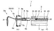
図1ないし図4は本発明の第1実施形態に係り、図1は内視鏡システムの概略構成を示す説明図、図2は内視鏡用モジュールの1つである切開モジュールを示す説明図、図3は内視鏡の先端部及び内視鏡用モジュールの構造を示す説明断面図、図4は切開モジュールを装着した内視鏡の作用を示す図である。
【0013】
図1に示すように本実施形態の内視鏡システム1は、2つの電子内視鏡(以下第1の内視鏡、第2の内視鏡等と記載する)2,65、光源装置3、ビデオプロセッサ4、モニタ5及び処置手段である処置具を備え前記内視鏡2に着脱自在な複数の例えば内視鏡用モジュール6A,6B,6C,6Dを備えた第1の内視鏡用モジュール群6と、処置手段である処置具を備え前記内視鏡65に着脱自在な複数の例えば内視鏡用モジュール61,62,63,64を備えた第2の内視鏡用モジュール群60とで主に構成されている。
【0014】
前記第1の内視鏡1は、細長で可撓性を有する挿入部11と、この挿入部11の基端部に連設する操作部12と、この操作部12の側方から延出する可撓性を有するユニバーサルコード13とで構成されている。前記ユニバーサルコード13の端部には前記光源装置3に着脱自在に接続されるコネクタ14が設けられている。このコネクタ14の側部には信号コード15が接続されるようになっており、この信号コード15の図示しない電気コネクタを介して前記ビデオプロセッサ4に着脱自在に接続されるようになっている。
【0015】
前記第2の内視鏡65は、前記第1の内視鏡1と同様に細長で可撓性を有する挿入部66と、操作部67と、ユニバーサルコード68とで構成され、このユニバーサルコード68の端部にはコネクタ69が設けられている。このコネクタ69の側部には信号コード70が接続されるようになっており、この信号コード70の図示しない電気コネクタを介して前記ビデオプロセッサ4に着脱自在に接続されるようになっている。
なお、このビデオプロセッサ4には内視鏡画像を表示するモニタ5が接続されている。
【0016】
前記第1の内視鏡用モジュール群6の各内視鏡用モジュールは、弾性を有するエラストマーで略筒状に形成されたモジュール本体7と、処置又は検査の目的により異なる処置手段と、この処置手段を前記内視鏡2に取り付けるモジュール側接続具8とで構成されており、本実施形態においては前記処置手段としてスネア9aを備えた切開モジュール6A、把持部材9bを備えた把持モジュール6B、生検鉗子9cを備えた生検モジュール6C、バスケット型回収具9dを備えた回収モジュール6Dがそれぞれ用意されている。なお、前記モジュール本体7は、高周波を使用した処置時に電流が内視鏡2側に漏れて検査者に漏電することを防止するため少なくとも本体外表面に絶縁体を設けた構成、又は本体全体を絶縁体である樹脂部材で形成する構成になっている。
【0017】
一方、前記第2の内視鏡用モジュール群60の各内視鏡用モジュールも前記第1の内視鏡用モジュール群6と同様に、弾性を有するエラストマーで略筒状に形成されたモジュール本体71と、処置又は検査の目的により異なる処置手段と、この処置手段を前記内視鏡65に取り付けるモジュール側接続具75とで構成されており、前記処置手段としては例えば、スネア9aを備えた切開モジュール61、把持部材9bを備えた把持モジュール62、生検鉗子9cを備えた生検モジュール63、バスケット型回収具9dを備えた回収モジュール64が用意されている。なお、前記モジュール本体71は、高周波を使用した処置時に電流が内視鏡65側に漏れて検査者に漏電することを防止するため少なくとも本体外表面に絶縁体を設けた構成、又は本体全体を絶縁体である樹脂部材で形成する構成になっている。
【0018】
また、前記内視鏡2の挿入部11の先端には前記第1の内視鏡用モジュール群6のモジュール本体7を配置する先端部16が設けてあり、この先端部16からは前記第1の内視鏡用モジュール群6の各内視鏡用モジュール6A,6B,6C,6Dに設けられているモジュール側接続具8と一体的に接続される内視鏡側接続具21が設けてある。この内視鏡側接続具21の基端部からは伝達ワイヤ22が延出しており、この伝達ワイヤ22は挿入部11内を通って前記操作部12に設けられている操作ノブ17に接続されている。この操作ノブ17を操作することによって、先端部16に配設された第1の内視鏡用モジュール群6の内視鏡用モジュールの処置手段が操作されるようになっている。
【0019】
一方、前記内視鏡65の挿入部66の先端には前記第2の内視鏡用モジュール群60のモジュール本体71を配置する先端部80が設けてあり、この先端部80からは前記第2の内視鏡用モジュール群60の各内視鏡用モジュール61,62,63,64に設けられているモジュール側接続具75と一体的に接続される内視鏡側接続具81が設けてある。この内視鏡側接続具81の基端部からは伝達ワイヤ82が延出しており、この伝達ワイヤ82は挿入部66内を通って前記操作部67に設けられている操作ノブ85に接続されている。この操作ノブ85を操作することによって、先端部80に配設された第2の内視鏡用モジュール群60の内視鏡用モジュールの処置手段が操作されるようになっている。
【0020】
前記モジュール本体7の外表面には組合せ適合手段になる指標部7cが設けられており、この指標部7cには前記第1の内視鏡2に対応することを示す内視鏡2の機種名を略した記号等が表記されるようになっている。また、前記第1の内視鏡2の操作部12の外表面には組合せ適合手段になる指標部19が設けられており、この指標部19にはこの第1の内視鏡2の機種名を示す記号が表記されている。
【0021】
一方、前記モジュール本体71の外表面には指標部72が設けられており、この指標部72には前記第2の内視鏡65に対応することを示す内視鏡65の機種名を略した記号が表記されるようになっている。また、前記第2の内視鏡65の操作部67の外表面には指標部86が設けられており、この指標部86にはこの第2の内視鏡65の機種名を示す記号が表記されている。
【0022】
図2を参照して第1の内視鏡用モジュールと内視鏡の先端部16との関係を説明する。なお、本図は第1の内視鏡用モジュール群6のうち、スネア9aを備えた切開モジュール6Aである。
図に示すように内視鏡2の先端部16の先端面には前記伝達ワイヤ22が挿通配置される操作用チャンネル18の開口が設けられるとともに、このチャンネル開口以外の部分であり、図示しない観察光学系の前面に配置された観察窓41や体腔内を照らす照明光を照射する照明窓42、汚物の吸引や処置具の挿通を行う処置用チャンネル43、前記観察窓41や照明窓42を洗浄する水や空気を噴出する送気・送水ノズル51を配置する略D字形状の凸部52が形成されている。
【0023】
一方、第1の内視鏡用モジュール群6の切開モジュール61のモジュール本体7の先端面には前記内視鏡2の先端部16に形成した凸部52を嵌入する略D字形状のD字開口53が形成されている。このため、前記モジュール本体7を先端部16の所定位置まで装着することにより、前記凸部52が前記モジュール本体7のD字開口53に嵌入する。このとき、モジュール本体7の先端面と凸部52の先端面とが略同一面になる。なお、この先端部16の少なくとも凸部52の先端面には絶縁体が設けられている。
【0024】
前記モジュール本体7の指標部7cには例えば前記第1の内視鏡2の機種名であるGIF−250という記号を省略して表すG−250という記号が記されている。このため、前記図1で示した第1の内視鏡2の指標部19にはこの第1の内視鏡2の機種名を示す記号であるGIF−250の文字が記されている。
【0025】
なお、符号7bは後述する処置具挿通孔であり、符号8bは後述する処置用操作チューブであり、符号8cは後述する連結部材であり、符号8dは後述するストッパ部である。
【0026】
図3(a)の切開モジュールの断面図及び図3(b)の先端部の断面図を参照して切開モジュール及び内視鏡の先端部の構成を説明する。
同図(a)に示すように切開モジュール6Aを構成するスネア9aに設けられているモジュール側接続具8の基端部には雄ネジ部8aが形成されている。また、モジュール本体7にはこのモジュール本体7を前記先端部16に外嵌固定によって配置するため前記先端部16の外径寸法よりも内径寸法を小径に形成して内周面が先端部16の外周面に密着するようにした連結手段となる内部空間部7aと、前記スネア9aなどの処置手段を配置する処置具挿通孔7bが長手軸方向に平行に形成されている。
【0027】
前記切開モジュール6Aは、先端部に輪状に形成した切開部31を備え、後端部に前記モジュール側接続具8を設けたスネア9aと、前記モジュール本体7の処置具挿通孔7bに配置されてモジュール本体7に対して進退自在で、手元側方向への抜け止めとなるストッパ部8dを有するとともに、前記モジュール側接続具8が進退自在に配置される透孔を有するパイプ形状の処置用操作チューブ8bと、この処置用操作チューブ8bの基端部に先端部を外嵌固定した基端部内周面に端面から先端側に向かって徐々に細径になるテーパー部を設けた連結部材8cとで構成されている。
【0028】
一方、図3(b)に示すように内視鏡2には操作用チャンネル18が形成されており、この操作用チャンネル18内には前記内視鏡側接続具21及び伝達ワイヤ22を進退自在に配置した操作チューブ23が進退自在に挿入配置されるようになっている。また、前記内視鏡側接続具21は筒状に形成されており、内孔には前記モジュール側接続具8の基端部に形成されている雄ネジ部8aと螺合する雌ネジ24が形成されている。なお、前記伝達ワイヤ22と操作チューブ23との基端部は、それぞれ前記操作部12に設けられている操作ノブ17に接続されており、それぞれ独立して進退操作可能になっている。
【0029】
ここで、切開モジュール6Aを内視鏡2の先端部16に装着する手順を図3(a),(b)を参照して説明する。
まず、伝達ワイヤ22の先端に設けられている内視鏡側接続具21を操作用チャンネル18内に配置されている操作チューブ23から突出させるとともに、スネア9aの後端部に配設されているモジュール側接続具8を連結部材8cから突出させる。そして、このモジュール側接続具8の雄ネジ部8aと前記内視鏡側接続具21の雌ネジ24とを螺合して、伝達ワイヤ22とスネア9aとを一体的に接続する。
【0030】
次に、前記操作チューブ23の先端部を切開モジュール6Aの連結部材8cのテーパ部に圧入する。このことによって、操作チューブ23と連結部材8cとが一体的に連結固定される。
【0031】
次いで、モジュール本体7の内部空間部7aを内視鏡2の先端部16に外嵌して圧入固定する。このとき、前記内視鏡2の操作用チャンネル18及びD字開口53とモジュール本体7の処置具挿通孔7b及び凸部52との位置を一致させてモジュール本体7を装着していく。そして、前記凸部52が前記モジュール本体7のD字開口53に嵌入してモジュール本体7の先端面と凸部52の先端面とを略同一面にしてモジュール本体7の先端部16への装着が完了する。
【0032】
なお、これまで第1の内視鏡2と第1の内視鏡用モジュール群6の切開モジュール6Aの着脱構造について述べたが他の内視鏡用モジュール6B,6C,6Dの着脱構造も同様であるとともに、前記第2の内視鏡65と前記第2の内視鏡用モジュール群60の内視鏡用モジュール61,62,63,64との着脱構造も前記第1の内視鏡2と第1の内視鏡用モジュール群6の各内視鏡用モジュール6A,6B,6C,6Dとの着脱構造と同様である。
【0033】
また、前記第1の内視鏡用モジュール群6に含まれる切開モジュール6A,把持モジュール6B,生検モジュール6C,回収モジュール6Dのモジュール本体7の指標部7cにはいずれも第1の内視鏡2と対応することを示す前記第1の内視鏡2を表すG−250という記号が記され、前記第2の内視鏡用モジュール群60に含まれる切開モジュール61,把持モジュール62,生検モジュール63,回収モジュール64のモジュール本体71の指標部75にはいずれも第2内視鏡65と対応することを示す前記第2内視鏡65の機種名であるCF−M250を表す省略記号であるC−250の記号が記されている。なお、前記第2の内視鏡65の指標部86には、この第2の内視鏡65の機種名を示すCF−M250の文字が記載されている。
【0034】
さらに、上述した実施形態においては内視鏡システム1として、第1の内視鏡2及びこの第1の内視鏡2に組み合わされる第1の内視鏡用モジュール群6からなるグループと、第2の内視鏡65及びこの第2の内視鏡65に組み合わされる第2の内視鏡用モジュール群60からなるグループの2つのグループを有する内視鏡システム1を示したが、内視鏡システム1は内視鏡及びこの内視鏡に組み合わされる内視鏡用モジュール群からなるグループを3つ以上有する構成であってもよい。そして、グループが異なる毎に、指標部に記載される記号、文字が異なっている。
【0035】
図4を参照して切開モジュール6Aを先端部16に装着した内視鏡2の操作及び作用を説明する。
まず、切開モジュール6Aを先端部16に装着した内視鏡2を例えば体腔内に挿入して切開モジュール6Aを患部近傍に配置する。
次に、切開したい患部37をスネア9aの切開部31内に配置する。続いて、操作ノブ17を操作し、操作チューブ23を先端面から突出させるように前進させていく。このことにより、連結部材8cを介して処置用操作チューブ8bが患部37側に押し出されていくので、スネア9aが処置用操作チューブ8b内に引き込まれた状態になって、切開部31が患部37の根元部を締め付けていく。
【0036】
そして、この状態で、今度はスネア9aを手元側に引き込むように、前記操作ノブ17を操作する。すると、前記スネア9aが処置用操作チューブ8b内に引き込まれていくことにより、患部37の根元部が切開部31によってさらに締め付けられた状態になる。
【0037】
次いで、この締め付け状態を保持して、切開モジュール6Aに高周波電流を流す。このことによって、患部37は根本から切断され、処置が完了する。そして、処置完了後、内視鏡2を体腔内から抜去し、切開モジュール6Aを内視鏡2から取り外す。その取り外し手順は、取付け時の逆であり、まずモジュール本体7を先端部16から取り外す。次に、操作チューブ23と連結部材8cとを取り外す。次いで、内視鏡側接続具21の雌ネジ24とモジュール側接続具8の雄ネジ部8aとの螺合を解除する。このことにより、内視鏡2と切開モジュール6Aとが分離される。この状態でそれぞれ洗滌・消毒を行い、その後保管する。
【0038】
このように、内視鏡とこの内視鏡に組み合わされる内視鏡用モジュール群とからなるグループを複数有する内視鏡システムにおいて、1つの内視鏡用モジュールを所定の内視鏡に装着する場合、グループの数だけ対応する内視鏡及び内視鏡用モジュールが存在するが、内視鏡及びこの内視鏡に組み合わされる内視鏡用モジュール群の各内視鏡用モジュールに、内視鏡とこの内視鏡に組み合わされる内視鏡用モジュール群とを表す記号や文字などの指標を設けたことにより、この指標を目視によって確認することによって、どの内視鏡用モジュールとどの内視鏡とが適合する組合せであるかを容易に判断することができる。
【0039】
このことにより、内視鏡と内視鏡用モジュール群との組合せを間違えることによって発生する装着不良や無理な装着によって必要十分な性能を発揮できない等の不都合が解消される。特に、第1の内視鏡が主に口から食道、胃、十二指腸等に挿入される上部消化管用で、第2の内視鏡が肛門から大腸などに挿入される下部消化管用である場合に、内視鏡と内視鏡用モジュールとの組合せを間違えることが防止される。
【0040】
なお、組合せ適合手段となる指標部を設け、その指標部に記号や文字を記載する代わりに、例えば第1の内視鏡用モジュール群のモジュール本体の色と、第2の内視鏡用モジュール群のモジュール本体の色とを異なる色、例えば、第1の内視鏡用モジュールのモジュール本体の色を黄色に着色し、第2の内視鏡用モジュール群のモジュール本体の色を緑色に着色し、モジュール群に対応する第1の内視鏡の先端部の色を黄色に着色し、第2の内視鏡の先端部の色を緑色に着色することによって、どの内視鏡用モジュールがどの内視鏡に適合するかを瞬時に判断することができる。このとき、モジュール本体及び内視鏡の先端部の全体を着色するようにしても部分的に着色するようにしてもよい。例えば、モジュール本体及び内視鏡の先端部が共に黒又は透明等で形成されていた場合には、モジュール本体に設けた指標部をそれぞれ黄色、緑色に着色し、内視鏡の指標部を黄色、緑色にそれぞれ着色する。
【0041】
また、前記第1の内視鏡2が主に口から食道、胃、十二指腸等に挿入される上部消化管用で、第2の内視鏡65が肛門から大腸などに挿入される下部消化管用である場合、内視鏡と内視鏡用モジュールとの組合せを間違えることを防止するために、上部用と下部用の内視鏡の外径寸法に差を付けるようにしてもよい。
【0042】
つまり、内視鏡用モジュールのモジュール本体7とモジュール本体71のサイズ及び内視鏡の先端部16と先端部80とのサイズとを明らかに異なるものにする。例えば、先端部16の外径を9mm、モジュール本体7のは外径を11mmとし、先端部80の外形を12mm、モジュール本体71の外径を14mmとした場合、たとえモジュール本体と先端部との色が同じ場合であっても、外径寸法の差が10%以上であれば、一見して違いを判別することができる。このことにより、色分けの必要がなくなるので製造がより容易になる。前記モジュール本体7及びモジュール本体71は外径だけでなく、嵌合部の寸法も先端部16,先端部80に合わせてサイズが異なっている。
【0043】
さらに、上部消化管用の内視鏡が下部消化管用の内視鏡より太径であることが場合によってはあるが、一般的に、上部消化管用の内視鏡は、下部消化管用の内視鏡よりも細い。このため、前記第1の内視鏡2が上部用で第2の内視鏡65が下部用とした場合、モジュール本体7とモジュール本体71、先端部16と先端部80とにサイズ差があるのは不自然でないので、そのサイズ差を10%以上の差にすることによって、どのモジュールがどの機種の内視鏡に適合するかの判断を容易にしている。
【0044】
図5は本発明の第2実施形態に係る内視鏡の挿入部の先端部とモジュール本体との他の構成を示す説明図である。
【0045】
前記図4に示したように切開モジュール6Aを先端部16に装着した内視鏡2で処置を行う場合、前記先端部16に装着したモジュール本体7には長手軸方向の負荷(外力)がかかることが多い。このため、前記モジュール本体7が先端部16に対して圧入によって固定される構成の場合、装着作業性を考慮していることからその固定強度をそれほど強固にすることができない。このため、万一モジュール本体7が先端部16から外れたときには雄ネジ部8aと雌ネジ24とが螺合接続されているのでこの切開モジュール6Aが完全に第1の内視鏡6から外れることはないが、十分な処置性能を発揮することができなくなったり、前記雄ネジ部8a及び雌ネジ24に負荷が集中して破壊されるおそれがある。
【0046】
このため、本実施形態においては使用中に内視鏡用モジュールが内視鏡から外れることを防止する内視鏡システムを提供するためモジュール本体を内視鏡の先端部に圧入するとともに、ねじによって螺合固定している。
つまり、図5に示すようにねじ90を用意する一方、モジュール本体7の側周面に長手軸に直交する向きに貫通して前記ねじ90が挿通する透孔91を形成し、第1の内視鏡2の先端部16の前記モジュール本体7の透孔91に対応する位置に前記ねじ90が螺合する雌ネジ92を設けている。このことによって、モジュール本体7を先端部16に完全に圧入した状態で前記透孔91と前記雌ネジ92とを一致させ、前記ねじ90を透孔91を介して雌ネジ92に螺合することによって、前記モジュール本体7が挿入軸長手方向に移動することを防止した状態で内視鏡2の先端部16に一体的に固定される。その他の構成及び作用は前記第1実施形態と同様であり、同部材には同符合を付して説明を省略する。
【0047】
このように、内視鏡の先端部にモジュール本体を圧入した後、ねじによってモジュール本体が内視鏡の先端部の長手軸方向に移動することを防止するように一体的に固定したことにより、モジュール本体と内視鏡の先端部とを強固に固定することができる。
【0048】
このことにより、内視鏡用モジュールが検査或いは処置中に内視鏡の先端部から外れることや位置ずれして性能を損ねることが防止される。
【0049】
なお、第1の内視鏡用モジュール群6の切開モジュール6Aと先端部16との着脱構造について述べたが他の内視鏡用モジュール6B,6C,6Dの着脱構造も同様である。また、前記第2の内視鏡65と前記第2の内視鏡用モジュール群60の内視鏡用モジュール61,62,63,64との着脱構造も前記第1の内視鏡2と第1の内視鏡用モジュール群6の各内視鏡用モジュール6A,6B,6C,6Dとの着脱構造と同様である。
【0050】
さらに、内視鏡が下部消化管用の場合、曲がりくねった大腸内に、挿入部の押し引きや捻り操作を頻繁に行いながら長い時間をかけて挿入が行われるので、上部消化管用の内視鏡よりも挿入部により過酷な負荷(外力)がかかるので、下部消化管用の内視鏡だけにねじを設ける構成にしてもよい。このことによって、下部消化管用の内視鏡と内視鏡用モジュールとのグループと、上部消化管用の内視鏡と内視鏡用モジュールとのグループとの違いを前記透孔及び雌ネジ部の有無によって視認することができる。
【0051】
又、ねじによる固定部を1つだけではなく複数設けるようにしてもよい。このことによって、固定強度をさらに強固にしてモジュール本体を内視鏡の先端部に固定することができるとともに、下部消化管用の内視鏡に複数のねじによる固定部を設けることによって、ねじによる固定部の数の違いによって内視鏡と内視鏡用モジュールとのグループの違いを視認できるようにしてもよい。
【0052】
さらに、ねじの長手軸方向に対する位置をグループ毎に変えることによって、グループの違いを視認することができるとともに、誤装着を防止することができる。
【0053】
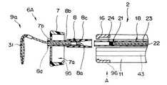
図6及び図7は本発明の第3実施形態に係り、図6は内視鏡の挿入部の先端部とモジュール本体との別の構成を示す説明図、図7は内視鏡の先端部を矢印A方向から見た図である。
【0054】
図6及び図7に示すように本実施形態においては内視鏡用モジュールが先端部から外れたり、位置ずれすることを防止するため、モジュール本体7の内周面の一部にロック手段となる突起部95を設ける一方、先端部16の外周面の一部に前記突起部95が挿入配置される溝部96を設けている。この溝部96は、先端面から長手軸方向に延出する直線溝部96aと、この直線溝部96aに対して略直交する位置決め用溝部97とで構成されている。
【0055】
このため、モジュール本体7を先端部16に装着するとき、前記モジュール本体7の突起部95と先端部16の直線溝部96aとを一致させた状態で、モジュール本体7を先端部16に装着し、このモジュール本体7を回転させることによって、突起部95が位置決め用溝部97に収まって、モジュール本体7の先端部16への装着が完了する。このことにより、モジュール本体7を先端部16に対して回転させるだけの簡単な作業でモジュール本体7を先端部16の長手軸方向にロックさせた状態にして外れや位置ずれを防止することができる。その他の構成及び作用・効果は上述した実施形態と同様であり、同部材には同符合を付して説明を省略する。
【0056】
なお、前記突起部が、直線溝部から位置決め用溝部に移るときに、クリック感やクリック音を発生させるようにすることにより、ユーザーはロックされたことを容易に確認することができる。
【0057】
また、内視鏡システムにおいて、一方の内視鏡と内視鏡用モジュールとに前記突起部及び溝部を設け、他方の内視鏡と内視鏡用モジュールとには前記突起部及び溝部を設けない構成にすることにより、内視鏡と内視鏡用モジュールとのグループを前記突起部及び溝部とで判別することができる。つまり、仮に、第1の内視鏡と第1の内視鏡用モジュール群のサイズと第2の内視鏡と第2の内視鏡用モジュール群とのサイズとが非常に似ていた場合でも、突起部及び溝部との有無によって、誤って、第1の内視鏡用モジュール群を第2の内視鏡に装着しようとしたとき、第2の内視鏡に突起部が通る溝が形成されていないので、装着することができず、誤装着しようとしたことをユーザーが認識して誤装着が防止される。
【0058】
さらに、誤装着を防止するため、第1の内視鏡2と第2の内視鏡65とでは内視鏡の中心軸に対する伝達ワイヤ22を挿通配置する操作用チャンネル18の相対位置を変える構成であってもよい。このとき、モジュール本体7とモジュール本体71に設ける処置具挿通孔7bの中心軸に対する相対位置は前記内視鏡に対応して異なっている。
【0059】
このことにより、仮に、先端部とモジュール本体のサイズが略同じ場合でも雄ネジ部と雌ネジとの位置が対応するグループ以外の組合せでは一致することがないので装着不能になって誤装着しようとしたことをユーザーが認識して誤装着が防止される。
【0060】
なお、本発明は、以上述べた実施形態のみに限定されるものではなく、発明の要旨を逸脱しない範囲で種々変形実施可能である。
【0061】
[付記]
以上詳述したような本発明の上記実施形態によれば、以下の如き構成を得ることができる。
【0062】
(1)処置手段を有する複数種類の内視鏡用モジュールと、この内視鏡用モジュールを内視鏡の挿入部先端部に取り付ける連結手段を有する複数種類の内視鏡とを具備する内視鏡システムにおいて、
前記複数種類の内視鏡用モジュール及び前記複数種類の内視鏡、それぞれに、内視鏡用モジュールと内視鏡との組合せが可能であるか否かを告知する組合せ適合手段を設けた内視鏡システム。
【0063】
(2)前記組合せ適合手段は、内視鏡用モジュールと内視鏡との組合せが可能であるか否かを目視にて認識することが可能な付記1記載の内視鏡システム。
【0064】
(3)前記組合せ適合手段は、内視鏡用モジュール及び内視鏡の外表面に記号、文字を設けて構成した付記2記載の内視鏡システム。
【0065】
(4)前記組合せ適合手段は、内視鏡用モジュール及び内視鏡の外表面の少なくとも一部を機種毎に色分けして形成した付記2記載の内視鏡システム。
【0066】
(5)前記組合せ適合手段は、内視鏡用モジュール及び内視鏡のサイズを機種毎に変えて構成した付記2記載の内視鏡システム。
【0067】
(6)前記組合せ適合手段は、内視鏡用モジュールと内視鏡との接続部付近の形状を機種毎に変えて構成した付記2記載の内視鏡システム。
【0068】
(7)前記組合せ適合手段は、内視鏡用モジュールと内視鏡とが不適合な組合せの場合、内視鏡用モジュールと内視鏡との接続が不可能である付記1記載の内視鏡システム。
【0069】
(8)前記連結手段にねじによる固定部を少なくとも1つ設けた付記1記載の内視鏡システム。
【0070】
(9)前記連結手段は、内視鏡と内視鏡用モジュール群とを組み合わせたグループ毎に異なる付記8記載の内視鏡システム。
【0071】
(10)前記連結手段のサイズが大きいほど接続強度を強くした付記1記載の内視鏡システム。
【0072】
(11)前記連結手段に、内視鏡用モジュールの挿入部先端部に対する長手軸方向の移動を規制するロック手段を設けた付記1記載の内視鏡システム。
【0073】
(12)前記ロック手段は1つの部材であり、この部材で軸方向の接続作業と周方向の接続作業とを行う付記11記載の内視鏡システム。
【0074】
(13)前記ロック手段は、規制状態になったとき、クリック感を伴う付記11記載の内視鏡システム。
【0075】
【発明の効果】
以上説明したように本発明によれば、どの内視鏡用モジュールとどの内視鏡とが同じグループであるか否かを、容易に判別することが可能な内視鏡システムを提供することができる。
【図面の簡単な説明】
【図1】図1ないし図4は本発明の第1実施形態に係り、図1は
内視鏡システムの概略構成を示す説明図
【図2】内視鏡用モジュールの1つである切開モジュールを示す説明図
【図3】内視鏡の先端部及び内視鏡用モジュールの構造を示す説明断面図
【図4】切開モジュールを装着した内視鏡の作用を示す図
【図5】本発明の第2実施形態に係る内視鏡の挿入部の先端部とモジュール本体との他の構成を示す説明図
【図6】図6及び図7は本発明の第3実施形態に係り、図6は内視鏡の挿入部の先端部とモジュール本体との別の構成を示す説明図
【図7】内視鏡の先端部を矢印A方向から見た図
【符号の説明】
1…内視鏡システム
2…第1の内視鏡
6…第1の内視鏡用モジュール群
7…モジュール本体
7c…指標部
19…指標部
60…第2の内視鏡用モジュール群
65…第2の内視鏡
71…モジュール本体
72…指標部
86…指標部[0001]
BACKGROUND OF THE INVENTION
The present invention relates to an endoscope system including an endoscope used in endoscopy and endoscopic surgery, and treatment equipment.
[0002]
[Prior art]
Conventionally, by inserting an elongated insertion portion into a body cavity, the internal organs of the body cavity are observed, and a treatment device (also referred to as a treatment tool) inserted into a treatment channel as necessary is used. Medical endoscopes capable of various therapeutic treatments are widely used.
[0003]
The treatment instrument has an elongated structure so that the treatment instrument channel of the endoscope has a small diameter (about 3 mm) and can be inserted into a long (about 2 m) lumen. For this reason, since there is a possibility that the elongated treatment device may be broken or broken when inserted into the treatment channel of the endoscope, the medical practitioner inserts the treatment device into the treatment channel. I had to pay close attention to.
[0004]
For example, in Japanese Patent Application Laid-Open No. 64-80335, in order to prevent breakage when the treatment instrument is inserted, a member having an appropriate elasticity is used for the treatment equipment, or the tip shape is made smooth. An endoscope that improves the performance is shown.
[0005]
In addition, when performing a treatment endoscopically, since the endoscope and the treatment tool are independent, the medical staff uses both hands to perform complicated endoscope operations and treatment tool operations. In addition, since several people including a caregiver have to operate the endoscope and the treatment tool, a skilled operation technique is required.
[0006]
[Problems to be solved by the invention]
However, as shown in the above-mentioned Japanese Patent Application Laid-Open No. 64-80335, the improvement of the material and the curved shape of the shape do not fundamentally solve the problem. In particular, when a special material is used, the material There are problems that it is difficult to obtain, is unsuitable for mass production due to complicated manufacturing methods, and treatment tools are expensive.
[0007]
In addition, after the treatment, when performing post-treatment such as washing and disinfection of slender treatment equipment, there is a problem that it is difficult to wash and it takes time for the post-treatment, and the treatment tool is stored and managed after the post-treatment. However, since the treatment tool is elongated, there is a problem that the storage space is increased.
[0008]
Furthermore, in order to provide an endoscope system that prevents the treatment tool from being damaged, is easy to operate under an endoscope, and can be stored in a small space, a plurality of types of endoscopes are provided for a plurality of different endoscopes. Although an endoscope system using a mirror module is also conceivable, there is a problem that it becomes difficult to determine which endoscope module and which endoscope can be combined.
[0009]
The present invention has been made in view of the above-described circumstances, and provides an endoscope system that can easily determine which endoscope module and which endoscope are in the same group. The purpose is to provide.
[0010]
[Means for Solving the Problems]
In order to achieve the above object, an endoscope system according to an aspect of the present invention includes a plurality of types of endoscope modules including treatment means, and the endoscope modules are attached to and detached from the distal end portion of the endoscope insertion portion. In an endoscope system having a plurality of types of endoscopes that can be freely attached,The endoscope module includes a module main body having an internal space portion in which an endoscope distal end portion is fitted and disposed;
A treatment means for treatment or inspection is provided on the front end side, a module side connection tool is provided on the rear end side, and an engagement portion is provided at the base end portion of the module side connection portion, so that the module main body is advanced and retracted. A module provided freely, and the endoscope includes an operation channel that opens at a distal end surface of the insertion portion, and a module-side connection of the endoscope module that is inserted into the operation channel so as to freely advance and retract. An endoscope-side connecting tool for arranging the tool, a transmission wire that extends rearward from the endoscope-side connecting tool, passes through the insertion portion, and is connected to the wire operation portion of the endoscope operation portion;An engaged portion that is provided on the endoscope-side connector and engages with an engaging portion that is provided at a base end portion of the module-side connector;Each of the plurality of types of endoscope modules and the plurality of types of endoscopes is provided with combination adapting means for notifying whether or not the combination of the endoscope module and the endoscope is possible.
[0011]
According to this configuration, an endoscopic module and an endoscope that are compatible are selected from among a plurality of endoscope modules having a treatment means and a plurality of endoscopes, and the endoscope module is selected. It can be attached to the distal end portion of the insertion portion of the endoscope to perform an endoscopic treatment, and can be stored in a state where the endoscope module is detached from the endoscope insertion portion.
[0012]
DETAILED DESCRIPTION OF THE INVENTION
Embodiments of the present invention will be described below with reference to the drawings.
1 to 4 relate to a first embodiment of the present invention, FIG. 1 is an explanatory view showing a schematic configuration of an endoscope system, and FIG. 2 is an explanatory view showing an incision module which is one of endoscope modules. FIG. 3 is an explanatory sectional view showing the structure of the distal end portion of the endoscope and the endoscope module, and FIG. 4 is a view showing the operation of the endoscope with the incision module attached.
[0013]
As shown in FIG. 1, the endoscope system 1 of the present embodiment includes two electronic endoscopes (hereinafter referred to as a first endoscope, a second endoscope, and the like) 2 and 65, and a light source device 3. For a first endoscope including a video processor 4, a monitor 5 and a treatment tool as a treatment means, and a plurality of
[0014]
The first endoscope 1 has an elongated and
[0015]
The
The video processor 4 is connected to a monitor 5 that displays an endoscopic image.
[0016]
Each of the endoscope modules in the first
[0017]
On the other hand, each of the endoscope modules in the second
[0018]
Further, a
[0019]
On the other hand, a
[0020]
The outer surface of the
[0021]
On the other hand, an
[0022]
The relationship between the first endoscope module and the
As shown in the figure, the distal end surface of the
[0023]
On the other hand, a substantially D-shaped D-shape in which a
[0024]
For example, the
[0025]
[0026]
With reference to the cross-sectional view of the incision module in FIG. 3A and the cross-sectional view of the distal end portion in FIG. 3B, the configuration of the incision module and the distal end portion of the endoscope will be described.
As shown in FIG. 6A, a male threaded
[0027]
The
[0028]
On the other hand, as shown in FIG. 3B, an
[0029]
Here, a procedure for mounting the
First, the
[0030]
Next, the distal end portion of the
[0031]
Next, the
[0032]
The attachment / detachment structure of the
[0033]
In addition, all of the
[0034]
Furthermore, in the above-described embodiment, the endoscope system 1 includes a group including the
[0035]
The operation and action of the
First, the
Next, the
[0036]
Then, in this state, the
[0037]
Next, a high-frequency current is passed through the
[0038]
As described above, in an endoscope system having a plurality of groups of an endoscope and an endoscope module group combined with the endoscope, one endoscope module is attached to a predetermined endoscope. In this case, there are endoscopes and endoscope modules corresponding to the number of groups, but each endoscope module in the endoscope and a group of endoscope modules combined with the endoscope is provided with an endoscope. By providing indicators such as symbols and characters representing the mirror and the endoscope module group to be combined with this endoscope, by confirming the indicators visually, which endoscope module and which endoscope It is possible to easily determine whether the mirror is a suitable combination.
[0039]
This eliminates inconveniences such as a mounting failure caused by a wrong combination of the endoscope and the endoscope module group and a necessary and sufficient performance due to an unreasonable mounting. In particular, when the first endoscope is for the upper gastrointestinal tract mainly inserted from the mouth into the esophagus, stomach, duodenum, etc., and the second endoscope is for the lower gastrointestinal tract inserted into the large intestine etc. from the anus Incorrect combination of the endoscope and the endoscope module is prevented.
[0040]
In addition, instead of providing an index portion serving as a combination adapting unit and writing a symbol or character in the index portion, for example, the color of the module body of the first endoscope module group and the second endoscope module A color different from the color of the module main body of the group, for example, the color of the module main body of the first endoscope module is colored yellow, and the color of the module main body of the second endoscope module group is colored green Then, the color of the tip of the first endoscope corresponding to the module group is colored yellow, and the color of the tip of the second endoscope is colored green. It is possible to instantly determine which endoscope is suitable. At this time, the entire module main body and the distal end portion of the endoscope may be colored or partially colored. For example, when both the module main body and the distal end of the endoscope are formed of black or transparent, the index portion provided on the module main body is colored yellow and green, respectively, and the index portion of the endoscope is yellow Colored green.
[0041]
The
[0042]
That is, the size of the module
[0043]
Furthermore, in some cases, the endoscope for the upper gastrointestinal tract is larger in diameter than the endoscope for the lower gastrointestinal tract, but in general, an endoscope for the upper gastrointestinal tract is generally an endoscope for the lower gastrointestinal tract. Thinner than. For this reason, when the
[0044]
FIG. 5 is an explanatory view showing another configuration of the distal end portion of the insertion portion and the module body of the endoscope according to the second embodiment of the present invention.
[0045]
As shown in FIG. 4, when a treatment is performed with the
[0046]
Therefore, in this embodiment, in order to provide an endoscope system that prevents the endoscope module from being detached from the endoscope during use, the module main body is press-fitted into the distal end portion of the endoscope, Screwed and fixed.
That is, as shown in FIG. 5, while the
[0047]
Thus, after the module main body is press-fitted into the distal end portion of the endoscope, it is integrally fixed so as to prevent the module main body from moving in the longitudinal axis direction of the distal end portion of the endoscope by a screw. The module main body and the distal end portion of the endoscope can be firmly fixed.
[0048]
This prevents the endoscope module from being detached from the distal end portion of the endoscope during the examination or treatment or being displaced to impair the performance.
[0049]
Although the attachment / detachment structure between the
[0050]
Furthermore, when the endoscope is for the lower gastrointestinal tract, insertion is performed over a long period of time while frequently pushing and pulling and twisting the insertion part into the tortuous colon. In addition, since a severe load (external force) is applied to the insertion portion, only the endoscope for the lower digestive tract may be provided with a screw. Accordingly, the difference between the group of the endoscope for the lower gastrointestinal tract and the module for the endoscope and the group of the endoscope for the upper gastrointestinal tract and the module for the endoscope can be determined. It can be visually recognized by the presence or absence.
[0051]
Moreover, you may make it provide not only one fixing part with a screw but multiple. As a result, the fixing strength can be further strengthened, and the module body can be fixed to the distal end portion of the endoscope, and the fixing portion by a plurality of screws can be fixed to the endoscope for the lower gastrointestinal tract. The difference in the group between the endoscope and the endoscope module may be made visible by the difference in the number of parts.
[0052]
Furthermore, by changing the position of the screw in the longitudinal axis direction for each group, it is possible to visually recognize the difference between the groups and to prevent erroneous mounting.
[0053]
6 and 7 relate to the third embodiment of the present invention, FIG. 6 is an explanatory view showing another configuration of the distal end portion of the insertion portion of the endoscope and the module body, and FIG. 7 is the distal end portion of the endoscope. It is the figure which looked at from the arrow A direction.
[0054]
As shown in FIGS. 6 and 7, in this embodiment, in order to prevent the endoscope module from being removed from the tip portion or displaced, a lock means is provided on a part of the inner peripheral surface of the
[0055]
For this reason, when the module
[0056]
When the protrusion moves from the linear groove to the positioning groove, the user can easily confirm that the protrusion is locked by generating a click feeling and a clicking sound.
[0057]
Further, in the endoscope system, the projection and the groove are provided in one endoscope and the endoscope module, and the projection and the groove are provided in the other endoscope and the endoscope module. By adopting the configuration, the group of the endoscope and the endoscope module can be discriminated by the protrusion and the groove. In other words, if the size of the first endoscope and the first endoscope module group is very similar to the size of the second endoscope and the second endoscope module group However, when the first endoscope module group is erroneously attached to the second endoscope depending on the presence or absence of the protrusion and the groove, there is a groove through which the protrusion passes through the second endoscope. Since it is not formed, it cannot be mounted, and the user recognizes that he / she tried to mount it incorrectly, thereby preventing erroneous mounting.
[0058]
Further, in order to prevent erroneous mounting, the
[0059]
As a result, even if the size of the tip and the module body are substantially the same, the positions of the male screw and the female screw will not match in a combination other than the corresponding group, so that it becomes impossible to install and tries to install incorrectly. The user recognizes that this is the case, and erroneous mounting is prevented.
[0060]
It should be noted that the present invention is not limited to the embodiments described above, and various modifications can be made without departing from the spirit of the invention.
[0061]
[Appendix]
According to the embodiment of the present invention as described above in detail, the following configuration can be obtained.
[0062]
(1) An endoscope comprising a plurality of types of endoscope modules having treatment means and a plurality of types of endoscopes having connecting means for attaching the endoscope module to the distal end portion of the insertion portion of the endoscope. In the mirror system,
An endoscope provided with combination adapting means for notifying whether the combination of the endoscope module and the endoscope is possible for each of the plurality of types of endoscope modules and the plurality of types of endoscopes. Endoscopic system.
[0063]
(2) The endoscope system according to supplementary note 1, wherein the combination adaptation unit can visually recognize whether or not the combination of the endoscope module and the endoscope is possible.
[0064]
(3) The endoscope system according to
[0065]
(4) The endoscope system according to
[0066]
(5) The endoscope system according to
[0067]
(6) The endoscope system according to
[0068]
(7) The endoscope according to appendix 1, wherein the combination adapting unit cannot connect the endoscope module and the endoscope when the endoscope module and the endoscope are incompatible combinations. system.
[0069]
(8) The endoscope system according to appendix 1, wherein the connecting means is provided with at least one fixing portion using screws.
[0070]
(9) The endoscope system according to
[0071]
(10) The endoscope system according to appendix 1, wherein the connection strength is increased as the size of the coupling means is increased.
[0072]
(11) The endoscope system according to appendix 1, wherein the coupling means is provided with a lock means for restricting movement in the longitudinal axis direction with respect to the distal end portion of the insertion portion of the endoscope module.
[0073]
(12) The endoscope system according to
[0074]
(13) The endoscope system according to
[0075]
【The invention's effect】
As described above, according to the present invention, it is possible to provide an endoscope system that can easily determine which endoscope module and which endoscope are in the same group. it can.
[Brief description of the drawings]
1 to 4 relate to a first embodiment of the present invention, and FIG.
Explanatory drawing which shows schematic structure of an endoscope system
FIG. 2 is an explanatory view showing an incision module which is one of the endoscope modules.
FIG. 3 is an explanatory cross-sectional view showing the structure of the distal end portion of the endoscope and the endoscope module.
FIG. 4 is a diagram showing an operation of an endoscope equipped with an incision module.
FIG. 5 is an explanatory view showing another configuration of the distal end portion of the insertion portion and the module body of the endoscope according to the second embodiment of the present invention.
6 and 7 relate to a third embodiment of the present invention, and FIG. 6 is an explanatory view showing another configuration of the distal end portion of the insertion portion of the endoscope and the module main body.
7 is a view of the distal end portion of the endoscope as viewed from the direction of arrow A. FIG.
[Explanation of symbols]
1. Endoscope system
2 ... First endoscope
6 ... First endoscope module group
7. Module body
7c: Indicator part
19 ... Indicator part
60 ... Second endoscope module group
65. Second endoscope
71 ... Module body
72: Indicator section
86 ... Indicator part
Claims (4)
Translated fromJapanese前記内視鏡用モジュールは、
内視鏡先端部を外嵌配置する内部空間部を有するモジュール本体と、
先端側に処置又は検査用の処置手段を有し、後端側にモジュール側接続具を設け、このモジュール側接続部の基端部に係合部を有して、前記モジュール本体に対して進退自在に設けられたモジュールと、
を備え、
内視鏡は、
挿入部先端面に開口する操作用チャンネルと、
前記操作用チャンネル内に進退自在に挿入した、前記内視鏡用モジュールのモジュール側接続具を配置する内視鏡側接続具と、
前記内視鏡側接続具から後方側に延出され挿入部内を挿通して内視鏡操作部のワイヤ操作部に接続される伝達ワイヤと、
前記内視鏡側接続具に設けて前記モジュール側接続具の基端部に設けられている係合部に係合する被係合部と、
を備え、
前記複数種類の内視鏡用モジュール及び前記複数種類の内視鏡のそれぞれに、内視鏡モジュールと内視鏡との組み合わせが可能であるか否かを告知する組み合わせ適合手段を設けたことを特徴とする内視鏡システム。Endoscope system having a plurality of types of endoscope modules provided with treatment means, and a plurality of types of endoscopes capable of detachably attaching the endoscope module to the distal end portion of the endoscope insertion portion In
The endoscope module is
A module main body having an internal space portion in which the distal end portion of the endoscope is externally fitted; and
A treatment means for treatment or inspection is provided on the front end side, a module side connection tool is provided on the rear end side, and an engagement portion is provided at the base end portion of the module side connection portion, so that the module main body is advanced and retracted. Freely provided modules,
With
The endoscope
An operation channel opening in the distal end surface of the insertion portion;
An endoscope-side connector for disposing a module-side connector of the endoscope module, which is inserted into the operation channel so as to freely advance and retract;
A transmission wire that extends rearward from the endoscope-side connector and is inserted through the insertion portion and connected to the wire operation portion of the endoscope operation portion;
An engaged portion that is provided on the endoscope-side connector and engages with an engaging portion that is provided at a proximal end portion of the module-side connector;
With
Each of the plurality of types of endoscope modules and the plurality of types of endoscopes is provided with combination adaptation means for notifying whether or not a combination of an endoscope module and an endoscope is possible. A featured endoscope system.
Priority Applications (2)
| Application Number | Priority Date | Filing Date | Title |
|---|---|---|---|
| JP18780398AJP3811291B2 (en) | 1998-07-02 | 1998-07-02 | Endoscope system |
| US09/128,320US6059719A (en) | 1997-08-06 | 1998-08-03 | Endoscope system |
Applications Claiming Priority (1)
| Application Number | Priority Date | Filing Date | Title |
|---|---|---|---|
| JP18780398AJP3811291B2 (en) | 1998-07-02 | 1998-07-02 | Endoscope system |
Publications (2)
| Publication Number | Publication Date |
|---|---|
| JP2000014632A JP2000014632A (en) | 2000-01-18 |
| JP3811291B2true JP3811291B2 (en) | 2006-08-16 |
Family
ID=16212521
Family Applications (1)
| Application Number | Title | Priority Date | Filing Date |
|---|---|---|---|
| JP18780398AExpired - Fee RelatedJP3811291B2 (en) | 1997-08-06 | 1998-07-02 | Endoscope system |
Country Status (1)
| Country | Link |
|---|---|
| JP (1) | JP3811291B2 (en) |
Cited By (1)
| Publication number | Priority date | Publication date | Assignee | Title |
|---|---|---|---|---|
| KR20190036781A (en) | 2017-09-28 | 2019-04-05 | (의료)길의료재단 | An assemble module type endoscope |
Families Citing this family (508)
| Publication number | Priority date | Publication date | Assignee | Title |
|---|---|---|---|---|
| US9060770B2 (en) | 2003-05-20 | 2015-06-23 | Ethicon Endo-Surgery, Inc. | Robotically-driven surgical instrument with E-beam driver |
| US20070084897A1 (en) | 2003-05-20 | 2007-04-19 | Shelton Frederick E Iv | Articulating surgical stapling instrument incorporating a two-piece e-beam firing mechanism |
| US8215531B2 (en) | 2004-07-28 | 2012-07-10 | Ethicon Endo-Surgery, Inc. | Surgical stapling instrument having a medical substance dispenser |
| US11890012B2 (en) | 2004-07-28 | 2024-02-06 | Cilag Gmbh International | Staple cartridge comprising cartridge body and attached support |
| US11998198B2 (en) | 2004-07-28 | 2024-06-04 | Cilag Gmbh International | Surgical stapling instrument incorporating a two-piece E-beam firing mechanism |
| US9072535B2 (en) | 2011-05-27 | 2015-07-07 | Ethicon Endo-Surgery, Inc. | Surgical stapling instruments with rotatable staple deployment arrangements |
| US9237891B2 (en) | 2005-08-31 | 2016-01-19 | Ethicon Endo-Surgery, Inc. | Robotically-controlled surgical stapling devices that produce formed staples having different lengths |
| US11484312B2 (en) | 2005-08-31 | 2022-11-01 | Cilag Gmbh International | Staple cartridge comprising a staple driver arrangement |
| US7669746B2 (en) | 2005-08-31 | 2010-03-02 | Ethicon Endo-Surgery, Inc. | Staple cartridges for forming staples having differing formed staple heights |
| US11246590B2 (en) | 2005-08-31 | 2022-02-15 | Cilag Gmbh International | Staple cartridge including staple drivers having different unfired heights |
| US7673781B2 (en) | 2005-08-31 | 2010-03-09 | Ethicon Endo-Surgery, Inc. | Surgical stapling device with staple driver that supports multiple wire diameter staples |
| US10159482B2 (en) | 2005-08-31 | 2018-12-25 | Ethicon Llc | Fastener cartridge assembly comprising a fixed anvil and different staple heights |
| US7934630B2 (en) | 2005-08-31 | 2011-05-03 | Ethicon Endo-Surgery, Inc. | Staple cartridges for forming staples having differing formed staple heights |
| US20070106317A1 (en) | 2005-11-09 | 2007-05-10 | Shelton Frederick E Iv | Hydraulically and electrically actuated articulation joints for surgical instruments |
| US11278279B2 (en) | 2006-01-31 | 2022-03-22 | Cilag Gmbh International | Surgical instrument assembly |
| US20120292367A1 (en) | 2006-01-31 | 2012-11-22 | Ethicon Endo-Surgery, Inc. | Robotically-controlled end effector |
| US8708213B2 (en) | 2006-01-31 | 2014-04-29 | Ethicon Endo-Surgery, Inc. | Surgical instrument having a feedback system |
| US11224427B2 (en) | 2006-01-31 | 2022-01-18 | Cilag Gmbh International | Surgical stapling system including a console and retraction assembly |
| US20110024477A1 (en) | 2009-02-06 | 2011-02-03 | Hall Steven G | Driven Surgical Stapler Improvements |
| US8820603B2 (en) | 2006-01-31 | 2014-09-02 | Ethicon Endo-Surgery, Inc. | Accessing data stored in a memory of a surgical instrument |
| US7845537B2 (en) | 2006-01-31 | 2010-12-07 | Ethicon Endo-Surgery, Inc. | Surgical instrument having recording capabilities |
| US8186555B2 (en) | 2006-01-31 | 2012-05-29 | Ethicon Endo-Surgery, Inc. | Motor-driven surgical cutting and fastening instrument with mechanical closure system |
| US11793518B2 (en) | 2006-01-31 | 2023-10-24 | Cilag Gmbh International | Powered surgical instruments with firing system lockout arrangements |
| US9861359B2 (en) | 2006-01-31 | 2018-01-09 | Ethicon Llc | Powered surgical instruments with firing system lockout arrangements |
| US20110295295A1 (en) | 2006-01-31 | 2011-12-01 | Ethicon Endo-Surgery, Inc. | Robotically-controlled surgical instrument having recording capabilities |
| US7753904B2 (en) | 2006-01-31 | 2010-07-13 | Ethicon Endo-Surgery, Inc. | Endoscopic surgical instrument with a handle that can articulate with respect to the shaft |
| US8236010B2 (en) | 2006-03-23 | 2012-08-07 | Ethicon Endo-Surgery, Inc. | Surgical fastener and cutter with mimicking end effector |
| US8992422B2 (en) | 2006-03-23 | 2015-03-31 | Ethicon Endo-Surgery, Inc. | Robotically-controlled endoscopic accessory channel |
| US8322455B2 (en) | 2006-06-27 | 2012-12-04 | Ethicon Endo-Surgery, Inc. | Manually driven surgical cutting and fastening instrument |
| US10568652B2 (en) | 2006-09-29 | 2020-02-25 | Ethicon Llc | Surgical staples having attached drivers of different heights and stapling instruments for deploying the same |
| US10130359B2 (en) | 2006-09-29 | 2018-11-20 | Ethicon Llc | Method for forming a staple |
| US7506791B2 (en) | 2006-09-29 | 2009-03-24 | Ethicon Endo-Surgery, Inc. | Surgical stapling instrument with mechanical mechanism for limiting maximum tissue compression |
| US11980366B2 (en) | 2006-10-03 | 2024-05-14 | Cilag Gmbh International | Surgical instrument |
| EP1949863B1 (en)* | 2006-12-14 | 2011-10-19 | Ethicon Endo-Surgery, Inc. | A tissue clamp for endolumenal local excision of tissue |
| US8684253B2 (en) | 2007-01-10 | 2014-04-01 | Ethicon Endo-Surgery, Inc. | Surgical instrument with wireless communication between a control unit of a robotic system and remote sensor |
| US11291441B2 (en) | 2007-01-10 | 2022-04-05 | Cilag Gmbh International | Surgical instrument with wireless communication between control unit and remote sensor |
| US8632535B2 (en) | 2007-01-10 | 2014-01-21 | Ethicon Endo-Surgery, Inc. | Interlock and surgical instrument including same |
| US8652120B2 (en) | 2007-01-10 | 2014-02-18 | Ethicon Endo-Surgery, Inc. | Surgical instrument with wireless communication between control unit and sensor transponders |
| US20080169333A1 (en) | 2007-01-11 | 2008-07-17 | Shelton Frederick E | Surgical stapler end effector with tapered distal end |
| US11039836B2 (en) | 2007-01-11 | 2021-06-22 | Cilag Gmbh International | Staple cartridge for use with a surgical stapling instrument |
| US7673782B2 (en) | 2007-03-15 | 2010-03-09 | Ethicon Endo-Surgery, Inc. | Surgical stapling instrument having a releasable buttress material |
| US8893946B2 (en) | 2007-03-28 | 2014-11-25 | Ethicon Endo-Surgery, Inc. | Laparoscopic tissue thickness and clamp load measuring devices |
| US11564682B2 (en) | 2007-06-04 | 2023-01-31 | Cilag Gmbh International | Surgical stapler device |
| US8931682B2 (en) | 2007-06-04 | 2015-01-13 | Ethicon Endo-Surgery, Inc. | Robotically-controlled shaft based rotary drive systems for surgical instruments |
| US8408439B2 (en) | 2007-06-22 | 2013-04-02 | Ethicon Endo-Surgery, Inc. | Surgical stapling instrument with an articulatable end effector |
| US7753245B2 (en) | 2007-06-22 | 2010-07-13 | Ethicon Endo-Surgery, Inc. | Surgical stapling instruments |
| US11849941B2 (en) | 2007-06-29 | 2023-12-26 | Cilag Gmbh International | Staple cartridge having staple cavities extending at a transverse angle relative to a longitudinal cartridge axis |
| US8561870B2 (en) | 2008-02-13 | 2013-10-22 | Ethicon Endo-Surgery, Inc. | Surgical stapling instrument |
| US8573465B2 (en) | 2008-02-14 | 2013-11-05 | Ethicon Endo-Surgery, Inc. | Robotically-controlled surgical end effector system with rotary actuated closure systems |
| JP5410110B2 (en) | 2008-02-14 | 2014-02-05 | エシコン・エンド−サージェリィ・インコーポレイテッド | Surgical cutting / fixing instrument with RF electrode |
| US11986183B2 (en) | 2008-02-14 | 2024-05-21 | Cilag Gmbh International | Surgical cutting and fastening instrument comprising a plurality of sensors to measure an electrical parameter |
| US8657174B2 (en) | 2008-02-14 | 2014-02-25 | Ethicon Endo-Surgery, Inc. | Motorized surgical cutting and fastening instrument having handle based power source |
| US8758391B2 (en) | 2008-02-14 | 2014-06-24 | Ethicon Endo-Surgery, Inc. | Interchangeable tools for surgical instruments |
| US9179912B2 (en) | 2008-02-14 | 2015-11-10 | Ethicon Endo-Surgery, Inc. | Robotically-controlled motorized surgical cutting and fastening instrument |
| US7866527B2 (en) | 2008-02-14 | 2011-01-11 | Ethicon Endo-Surgery, Inc. | Surgical stapling apparatus with interlockable firing system |
| US8636736B2 (en) | 2008-02-14 | 2014-01-28 | Ethicon Endo-Surgery, Inc. | Motorized surgical cutting and fastening instrument |
| US7819298B2 (en) | 2008-02-14 | 2010-10-26 | Ethicon Endo-Surgery, Inc. | Surgical stapling apparatus with control features operable with one hand |
| US9585657B2 (en) | 2008-02-15 | 2017-03-07 | Ethicon Endo-Surgery, Llc | Actuator for releasing a layer of material from a surgical end effector |
| US20090206131A1 (en) | 2008-02-15 | 2009-08-20 | Ethicon Endo-Surgery, Inc. | End effector coupling arrangements for a surgical cutting and stapling instrument |
| US11272927B2 (en) | 2008-02-15 | 2022-03-15 | Cilag Gmbh International | Layer arrangements for surgical staple cartridges |
| US7954686B2 (en) | 2008-09-19 | 2011-06-07 | Ethicon Endo-Surgery, Inc. | Surgical stapler with apparatus for adjusting staple height |
| PL3476312T3 (en) | 2008-09-19 | 2024-03-11 | Ethicon Llc | Surgical stapler with apparatus for adjusting staple height |
| US8210411B2 (en) | 2008-09-23 | 2012-07-03 | Ethicon Endo-Surgery, Inc. | Motor-driven surgical cutting instrument |
| US9050083B2 (en) | 2008-09-23 | 2015-06-09 | Ethicon Endo-Surgery, Inc. | Motorized surgical instrument |
| US9005230B2 (en) | 2008-09-23 | 2015-04-14 | Ethicon Endo-Surgery, Inc. | Motorized surgical instrument |
| US9386983B2 (en) | 2008-09-23 | 2016-07-12 | Ethicon Endo-Surgery, Llc | Robotically-controlled motorized surgical instrument |
| US11648005B2 (en) | 2008-09-23 | 2023-05-16 | Cilag Gmbh International | Robotically-controlled motorized surgical instrument with an end effector |
| US8608045B2 (en) | 2008-10-10 | 2013-12-17 | Ethicon Endo-Sugery, Inc. | Powered surgical cutting and stapling apparatus with manually retractable firing system |
| US8517239B2 (en) | 2009-02-05 | 2013-08-27 | Ethicon Endo-Surgery, Inc. | Surgical stapling instrument comprising a magnetic element driver |
| RU2525225C2 (en) | 2009-02-06 | 2014-08-10 | Этикон Эндо-Серджери, Инк. | Improvement of drive surgical suturing instrument |
| US8444036B2 (en) | 2009-02-06 | 2013-05-21 | Ethicon Endo-Surgery, Inc. | Motor driven surgical fastener device with mechanisms for adjusting a tissue gap within the end effector |
| US8453907B2 (en) | 2009-02-06 | 2013-06-04 | Ethicon Endo-Surgery, Inc. | Motor driven surgical fastener device with cutting member reversing mechanism |
| US8851354B2 (en) | 2009-12-24 | 2014-10-07 | Ethicon Endo-Surgery, Inc. | Surgical cutting instrument that analyzes tissue thickness |
| US8220688B2 (en) | 2009-12-24 | 2012-07-17 | Ethicon Endo-Surgery, Inc. | Motor-driven surgical cutting instrument with electric actuator directional control assembly |
| US8608046B2 (en) | 2010-01-07 | 2013-12-17 | Ethicon Endo-Surgery, Inc. | Test device for a surgical tool |
| US8783543B2 (en) | 2010-07-30 | 2014-07-22 | Ethicon Endo-Surgery, Inc. | Tissue acquisition arrangements and methods for surgical stapling devices |
| US8360296B2 (en) | 2010-09-09 | 2013-01-29 | Ethicon Endo-Surgery, Inc. | Surgical stapling head assembly with firing lockout for a surgical stapler |
| US9289212B2 (en) | 2010-09-17 | 2016-03-22 | Ethicon Endo-Surgery, Inc. | Surgical instruments and batteries for surgical instruments |
| US8632525B2 (en) | 2010-09-17 | 2014-01-21 | Ethicon Endo-Surgery, Inc. | Power control arrangements for surgical instruments and batteries |
| US8733613B2 (en) | 2010-09-29 | 2014-05-27 | Ethicon Endo-Surgery, Inc. | Staple cartridge |
| US11812965B2 (en) | 2010-09-30 | 2023-11-14 | Cilag Gmbh International | Layer of material for a surgical end effector |
| US9113862B2 (en) | 2010-09-30 | 2015-08-25 | Ethicon Endo-Surgery, Inc. | Surgical stapling instrument with a variable staple forming system |
| US9055941B2 (en) | 2011-09-23 | 2015-06-16 | Ethicon Endo-Surgery, Inc. | Staple cartridge including collapsible deck |
| US11298125B2 (en) | 2010-09-30 | 2022-04-12 | Cilag Gmbh International | Tissue stapler having a thickness compensator |
| RU2013119928A (en) | 2010-09-30 | 2014-11-10 | Этикон Эндо-Серджери, Инк. | A STAPLING SYSTEM CONTAINING A RETAINING MATRIX AND A LEVELING MATRIX |
| US8893949B2 (en) | 2010-09-30 | 2014-11-25 | Ethicon Endo-Surgery, Inc. | Surgical stapler with floating anvil |
| US9220501B2 (en) | 2010-09-30 | 2015-12-29 | Ethicon Endo-Surgery, Inc. | Tissue thickness compensators |
| US9314246B2 (en) | 2010-09-30 | 2016-04-19 | Ethicon Endo-Surgery, Llc | Tissue stapler having a thickness compensator incorporating an anti-inflammatory agent |
| US9364233B2 (en) | 2010-09-30 | 2016-06-14 | Ethicon Endo-Surgery, Llc | Tissue thickness compensators for circular surgical staplers |
| US9332974B2 (en) | 2010-09-30 | 2016-05-10 | Ethicon Endo-Surgery, Llc | Layered tissue thickness compensator |
| US11925354B2 (en) | 2010-09-30 | 2024-03-12 | Cilag Gmbh International | Staple cartridge comprising staples positioned within a compressible portion thereof |
| US9301752B2 (en) | 2010-09-30 | 2016-04-05 | Ethicon Endo-Surgery, Llc | Tissue thickness compensator comprising a plurality of capsules |
| US9232941B2 (en) | 2010-09-30 | 2016-01-12 | Ethicon Endo-Surgery, Inc. | Tissue thickness compensator comprising a reservoir |
| US12213666B2 (en) | 2010-09-30 | 2025-02-04 | Cilag Gmbh International | Tissue thickness compensator comprising layers |
| US9788834B2 (en) | 2010-09-30 | 2017-10-17 | Ethicon Llc | Layer comprising deployable attachment members |
| US9629814B2 (en) | 2010-09-30 | 2017-04-25 | Ethicon Endo-Surgery, Llc | Tissue thickness compensator configured to redistribute compressive forces |
| US9351730B2 (en) | 2011-04-29 | 2016-05-31 | Ethicon Endo-Surgery, Llc | Tissue thickness compensator comprising channels |
| US10945731B2 (en) | 2010-09-30 | 2021-03-16 | Ethicon Llc | Tissue thickness compensator comprising controlled release and expansion |
| US9301753B2 (en) | 2010-09-30 | 2016-04-05 | Ethicon Endo-Surgery, Llc | Expandable tissue thickness compensator |
| US9277919B2 (en) | 2010-09-30 | 2016-03-08 | Ethicon Endo-Surgery, Llc | Tissue thickness compensator comprising fibers to produce a resilient load |
| US9016542B2 (en) | 2010-09-30 | 2015-04-28 | Ethicon Endo-Surgery, Inc. | Staple cartridge comprising compressible distortion resistant components |
| US9386988B2 (en) | 2010-09-30 | 2016-07-12 | Ethicon End-Surgery, LLC | Retainer assembly including a tissue thickness compensator |
| US9307989B2 (en) | 2012-03-28 | 2016-04-12 | Ethicon Endo-Surgery, Llc | Tissue stapler having a thickness compensator incorportating a hydrophobic agent |
| US8695866B2 (en) | 2010-10-01 | 2014-04-15 | Ethicon Endo-Surgery, Inc. | Surgical instrument having a power control circuit |
| US9211122B2 (en) | 2011-03-14 | 2015-12-15 | Ethicon Endo-Surgery, Inc. | Surgical access devices with anvil introduction and specimen retrieval structures |
| US9044229B2 (en) | 2011-03-15 | 2015-06-02 | Ethicon Endo-Surgery, Inc. | Surgical fastener instruments |
| US8926598B2 (en) | 2011-03-15 | 2015-01-06 | Ethicon Endo-Surgery, Inc. | Surgical instruments with articulatable and rotatable end effector |
| AU2012250197B2 (en) | 2011-04-29 | 2017-08-10 | Ethicon Endo-Surgery, Inc. | Staple cartridge comprising staples positioned within a compressible portion thereof |
| US11207064B2 (en) | 2011-05-27 | 2021-12-28 | Cilag Gmbh International | Automated end effector component reloading system for use with a robotic system |
| US8833632B2 (en) | 2011-09-06 | 2014-09-16 | Ethicon Endo-Surgery, Inc. | Firing member displacement system for a stapling instrument |
| US9050084B2 (en) | 2011-09-23 | 2015-06-09 | Ethicon Endo-Surgery, Inc. | Staple cartridge including collapsible deck arrangement |
| US9044230B2 (en) | 2012-02-13 | 2015-06-02 | Ethicon Endo-Surgery, Inc. | Surgical cutting and fastening instrument with apparatus for determining cartridge and firing motion status |
| US9078653B2 (en) | 2012-03-26 | 2015-07-14 | Ethicon Endo-Surgery, Inc. | Surgical stapling device with lockout system for preventing actuation in the absence of an installed staple cartridge |
| MX358135B (en) | 2012-03-28 | 2018-08-06 | Ethicon Endo Surgery Inc | Tissue thickness compensator comprising a plurality of layers. |
| JP6224070B2 (en) | 2012-03-28 | 2017-11-01 | エシコン・エンド−サージェリィ・インコーポレイテッドEthicon Endo−Surgery,Inc. | Retainer assembly including tissue thickness compensator |
| US9198662B2 (en) | 2012-03-28 | 2015-12-01 | Ethicon Endo-Surgery, Inc. | Tissue thickness compensator having improved visibility |
| BR112014024098B1 (en) | 2012-03-28 | 2021-05-25 | Ethicon Endo-Surgery, Inc. | staple cartridge |
| US9101358B2 (en) | 2012-06-15 | 2015-08-11 | Ethicon Endo-Surgery, Inc. | Articulatable surgical instrument comprising a firing drive |
| US9408606B2 (en) | 2012-06-28 | 2016-08-09 | Ethicon Endo-Surgery, Llc | Robotically powered surgical device with manually-actuatable reversing system |
| US11278284B2 (en) | 2012-06-28 | 2022-03-22 | Cilag Gmbh International | Rotary drive arrangements for surgical instruments |
| US20140001231A1 (en) | 2012-06-28 | 2014-01-02 | Ethicon Endo-Surgery, Inc. | Firing system lockout arrangements for surgical instruments |
| US9028494B2 (en) | 2012-06-28 | 2015-05-12 | Ethicon Endo-Surgery, Inc. | Interchangeable end effector coupling arrangement |
| US9119657B2 (en) | 2012-06-28 | 2015-09-01 | Ethicon Endo-Surgery, Inc. | Rotary actuatable closure arrangement for surgical end effector |
| JP6290201B2 (en) | 2012-06-28 | 2018-03-07 | エシコン・エンド−サージェリィ・インコーポレイテッドEthicon Endo−Surgery,Inc. | Lockout for empty clip cartridge |
| US12383267B2 (en) | 2012-06-28 | 2025-08-12 | Cilag Gmbh International | Robotically powered surgical device with manually-actuatable reversing system |
| US9125662B2 (en) | 2012-06-28 | 2015-09-08 | Ethicon Endo-Surgery, Inc. | Multi-axis articulating and rotating surgical tools |
| US9101385B2 (en) | 2012-06-28 | 2015-08-11 | Ethicon Endo-Surgery, Inc. | Electrode connections for rotary driven surgical tools |
| US9289256B2 (en) | 2012-06-28 | 2016-03-22 | Ethicon Endo-Surgery, Llc | Surgical end effectors having angled tissue-contacting surfaces |
| US20140005718A1 (en) | 2012-06-28 | 2014-01-02 | Ethicon Endo-Surgery, Inc. | Multi-functional powered surgical device with external dissection features |
| BR112014032776B1 (en) | 2012-06-28 | 2021-09-08 | Ethicon Endo-Surgery, Inc | SURGICAL INSTRUMENT SYSTEM AND SURGICAL KIT FOR USE WITH A SURGICAL INSTRUMENT SYSTEM |
| US9282974B2 (en) | 2012-06-28 | 2016-03-15 | Ethicon Endo-Surgery, Llc | Empty clip cartridge lockout |
| US9072536B2 (en) | 2012-06-28 | 2015-07-07 | Ethicon Endo-Surgery, Inc. | Differential locking arrangements for rotary powered surgical instruments |
| US9561038B2 (en) | 2012-06-28 | 2017-02-07 | Ethicon Endo-Surgery, Llc | Interchangeable clip applier |
| US9386985B2 (en) | 2012-10-15 | 2016-07-12 | Ethicon Endo-Surgery, Llc | Surgical cutting instrument |
| US9386984B2 (en) | 2013-02-08 | 2016-07-12 | Ethicon Endo-Surgery, Llc | Staple cartridge comprising a releasable cover |
| US9468438B2 (en) | 2013-03-01 | 2016-10-18 | Eticon Endo-Surgery, LLC | Sensor straightened end effector during removal through trocar |
| BR112015021082B1 (en) | 2013-03-01 | 2022-05-10 | Ethicon Endo-Surgery, Inc | surgical instrument |
| RU2672520C2 (en) | 2013-03-01 | 2018-11-15 | Этикон Эндо-Серджери, Инк. | Hingedly turnable surgical instruments with conducting ways for signal transfer |
| US9345481B2 (en) | 2013-03-13 | 2016-05-24 | Ethicon Endo-Surgery, Llc | Staple cartridge tissue thickness sensor system |
| US9629629B2 (en) | 2013-03-14 | 2017-04-25 | Ethicon Endo-Surgey, LLC | Control systems for surgical instruments |
| US9808244B2 (en) | 2013-03-14 | 2017-11-07 | Ethicon Llc | Sensor arrangements for absolute positioning system for surgical instruments |
| US9572577B2 (en) | 2013-03-27 | 2017-02-21 | Ethicon Endo-Surgery, Llc | Fastener cartridge comprising a tissue thickness compensator including openings therein |
| US9332984B2 (en) | 2013-03-27 | 2016-05-10 | Ethicon Endo-Surgery, Llc | Fastener cartridge assemblies |
| US9795384B2 (en) | 2013-03-27 | 2017-10-24 | Ethicon Llc | Fastener cartridge comprising a tissue thickness compensator and a gap setting element |
| BR112015026109B1 (en) | 2013-04-16 | 2022-02-22 | Ethicon Endo-Surgery, Inc | surgical instrument |
| US9826976B2 (en) | 2013-04-16 | 2017-11-28 | Ethicon Llc | Motor driven surgical instruments with lockable dual drive shafts |
| US9574644B2 (en) | 2013-05-30 | 2017-02-21 | Ethicon Endo-Surgery, Llc | Power module for use with a surgical instrument |
| US9775609B2 (en) | 2013-08-23 | 2017-10-03 | Ethicon Llc | Tamper proof circuit for surgical instrument battery pack |
| MX369362B (en) | 2013-08-23 | 2019-11-06 | Ethicon Endo Surgery Llc | Firing member retraction devices for powered surgical instruments. |
| US9839428B2 (en) | 2013-12-23 | 2017-12-12 | Ethicon Llc | Surgical cutting and stapling instruments with independent jaw control features |
| US9642620B2 (en) | 2013-12-23 | 2017-05-09 | Ethicon Endo-Surgery, Llc | Surgical cutting and stapling instruments with articulatable end effectors |
| US20150173756A1 (en) | 2013-12-23 | 2015-06-25 | Ethicon Endo-Surgery, Inc. | Surgical cutting and stapling methods |
| US20150173749A1 (en) | 2013-12-23 | 2015-06-25 | Ethicon Endo-Surgery, Inc. | Surgical staples and staple cartridges |
| US9724092B2 (en) | 2013-12-23 | 2017-08-08 | Ethicon Llc | Modular surgical instruments |
| US9681870B2 (en) | 2013-12-23 | 2017-06-20 | Ethicon Llc | Articulatable surgical instruments with separate and distinct closing and firing systems |
| US9962161B2 (en) | 2014-02-12 | 2018-05-08 | Ethicon Llc | Deliverable surgical instrument |
| JP6462004B2 (en) | 2014-02-24 | 2019-01-30 | エシコン エルエルシー | Fastening system with launcher lockout |
| US20140166724A1 (en) | 2014-02-24 | 2014-06-19 | Ethicon Endo-Surgery, Inc. | Staple cartridge including a barbed staple |
| US10013049B2 (en) | 2014-03-26 | 2018-07-03 | Ethicon Llc | Power management through sleep options of segmented circuit and wake up control |
| US9913642B2 (en) | 2014-03-26 | 2018-03-13 | Ethicon Llc | Surgical instrument comprising a sensor system |
| BR112016021943B1 (en) | 2014-03-26 | 2022-06-14 | Ethicon Endo-Surgery, Llc | SURGICAL INSTRUMENT FOR USE BY AN OPERATOR IN A SURGICAL PROCEDURE |
| US12232723B2 (en) | 2014-03-26 | 2025-02-25 | Cilag Gmbh International | Systems and methods for controlling a segmented circuit |
| US20150272580A1 (en) | 2014-03-26 | 2015-10-01 | Ethicon Endo-Surgery, Inc. | Verification of number of battery exchanges/procedure count |
| US10004497B2 (en) | 2014-03-26 | 2018-06-26 | Ethicon Llc | Interface systems for use with surgical instruments |
| US20150297225A1 (en) | 2014-04-16 | 2015-10-22 | Ethicon Endo-Surgery, Inc. | Fastener cartridges including extensions having different configurations |
| CN106456159B (en) | 2014-04-16 | 2019-03-08 | 伊西康内外科有限责任公司 | Fastener Cartridge Assembly and Nail Retainer Cover Arrangement |
| US10470768B2 (en) | 2014-04-16 | 2019-11-12 | Ethicon Llc | Fastener cartridge including a layer attached thereto |
| BR112016023825B1 (en) | 2014-04-16 | 2022-08-02 | Ethicon Endo-Surgery, Llc | STAPLE CARTRIDGE FOR USE WITH A SURGICAL STAPLER AND STAPLE CARTRIDGE FOR USE WITH A SURGICAL INSTRUMENT |
| US10327764B2 (en) | 2014-09-26 | 2019-06-25 | Ethicon Llc | Method for creating a flexible staple line |
| CN106456176B (en) | 2014-04-16 | 2019-06-28 | 伊西康内外科有限责任公司 | Fastener Cartridge Including Extensions With Different Configurations |
| US10045781B2 (en) | 2014-06-13 | 2018-08-14 | Ethicon Llc | Closure lockout systems for surgical instruments |
| BR112017004361B1 (en) | 2014-09-05 | 2023-04-11 | Ethicon Llc | ELECTRONIC SYSTEM FOR A SURGICAL INSTRUMENT |
| US10135242B2 (en) | 2014-09-05 | 2018-11-20 | Ethicon Llc | Smart cartridge wake up operation and data retention |
| US11311294B2 (en) | 2014-09-05 | 2022-04-26 | Cilag Gmbh International | Powered medical device including measurement of closure state of jaws |
| US10105142B2 (en) | 2014-09-18 | 2018-10-23 | Ethicon Llc | Surgical stapler with plurality of cutting elements |
| US11523821B2 (en) | 2014-09-26 | 2022-12-13 | Cilag Gmbh International | Method for creating a flexible staple line |
| CN107427300B (en) | 2014-09-26 | 2020-12-04 | 伊西康有限责任公司 | Surgical suture buttresses and auxiliary materials |
| US10076325B2 (en) | 2014-10-13 | 2018-09-18 | Ethicon Llc | Surgical stapling apparatus comprising a tissue stop |
| US9924944B2 (en) | 2014-10-16 | 2018-03-27 | Ethicon Llc | Staple cartridge comprising an adjunct material |
| US11141153B2 (en) | 2014-10-29 | 2021-10-12 | Cilag Gmbh International | Staple cartridges comprising driver arrangements |
| US10517594B2 (en) | 2014-10-29 | 2019-12-31 | Ethicon Llc | Cartridge assemblies for surgical staplers |
| US9844376B2 (en) | 2014-11-06 | 2017-12-19 | Ethicon Llc | Staple cartridge comprising a releasable adjunct material |
| US10736636B2 (en) | 2014-12-10 | 2020-08-11 | Ethicon Llc | Articulatable surgical instrument system |
| US9943309B2 (en) | 2014-12-18 | 2018-04-17 | Ethicon Llc | Surgical instruments with articulatable end effectors and movable firing beam support arrangements |
| US9844374B2 (en) | 2014-12-18 | 2017-12-19 | Ethicon Llc | Surgical instrument systems comprising an articulatable end effector and means for adjusting the firing stroke of a firing member |
| US10188385B2 (en) | 2014-12-18 | 2019-01-29 | Ethicon Llc | Surgical instrument system comprising lockable systems |
| US9844375B2 (en) | 2014-12-18 | 2017-12-19 | Ethicon Llc | Drive arrangements for articulatable surgical instruments |
| MX389118B (en) | 2014-12-18 | 2025-03-20 | Ethicon Llc | SURGICAL INSTRUMENT WITH AN ANVIL THAT CAN BE SELECTIVELY MOVED ON A DISCRETE, NON-MOBILE AXIS RELATIVE TO A STAPLE CARTRIDGE. |
| US10085748B2 (en) | 2014-12-18 | 2018-10-02 | Ethicon Llc | Locking arrangements for detachable shaft assemblies with articulatable surgical end effectors |
| US9987000B2 (en) | 2014-12-18 | 2018-06-05 | Ethicon Llc | Surgical instrument assembly comprising a flexible articulation system |
| US10117649B2 (en) | 2014-12-18 | 2018-11-06 | Ethicon Llc | Surgical instrument assembly comprising a lockable articulation system |
| US9993258B2 (en) | 2015-02-27 | 2018-06-12 | Ethicon Llc | Adaptable surgical instrument handle |
| US11154301B2 (en) | 2015-02-27 | 2021-10-26 | Cilag Gmbh International | Modular stapling assembly |
| US10180463B2 (en) | 2015-02-27 | 2019-01-15 | Ethicon Llc | Surgical apparatus configured to assess whether a performance parameter of the surgical apparatus is within an acceptable performance band |
| US10159483B2 (en) | 2015-02-27 | 2018-12-25 | Ethicon Llc | Surgical apparatus configured to track an end-of-life parameter |
| US10441279B2 (en) | 2015-03-06 | 2019-10-15 | Ethicon Llc | Multiple level thresholds to modify operation of powered surgical instruments |
| US10548504B2 (en) | 2015-03-06 | 2020-02-04 | Ethicon Llc | Overlaid multi sensor radio frequency (RF) electrode system to measure tissue compression |
| US9808246B2 (en) | 2015-03-06 | 2017-11-07 | Ethicon Endo-Surgery, Llc | Method of operating a powered surgical instrument |
| US10617412B2 (en) | 2015-03-06 | 2020-04-14 | Ethicon Llc | System for detecting the mis-insertion of a staple cartridge into a surgical stapler |
| US10245033B2 (en) | 2015-03-06 | 2019-04-02 | Ethicon Llc | Surgical instrument comprising a lockable battery housing |
| US10045776B2 (en) | 2015-03-06 | 2018-08-14 | Ethicon Llc | Control techniques and sub-processor contained within modular shaft with select control processing from handle |
| US9901342B2 (en) | 2015-03-06 | 2018-02-27 | Ethicon Endo-Surgery, Llc | Signal and power communication system positioned on a rotatable shaft |
| US9924961B2 (en) | 2015-03-06 | 2018-03-27 | Ethicon Endo-Surgery, Llc | Interactive feedback system for powered surgical instruments |
| JP2020121162A (en) | 2015-03-06 | 2020-08-13 | エシコン エルエルシーEthicon LLC | Time dependent evaluation of sensor data to determine stability element, creep element and viscoelastic element of measurement |
| US9993248B2 (en) | 2015-03-06 | 2018-06-12 | Ethicon Endo-Surgery, Llc | Smart sensors with local signal processing |
| US9895148B2 (en) | 2015-03-06 | 2018-02-20 | Ethicon Endo-Surgery, Llc | Monitoring speed control and precision incrementing of motor for powered surgical instruments |
| US10687806B2 (en) | 2015-03-06 | 2020-06-23 | Ethicon Llc | Adaptive tissue compression techniques to adjust closure rates for multiple tissue types |
| US10433844B2 (en) | 2015-03-31 | 2019-10-08 | Ethicon Llc | Surgical instrument with selectively disengageable threaded drive systems |
| US10154841B2 (en) | 2015-06-18 | 2018-12-18 | Ethicon Llc | Surgical stapling instruments with lockout arrangements for preventing firing system actuation when a cartridge is spent or missing |
| US10835249B2 (en) | 2015-08-17 | 2020-11-17 | Ethicon Llc | Implantable layers for a surgical instrument |
| US10980538B2 (en) | 2015-08-26 | 2021-04-20 | Ethicon Llc | Surgical stapling configurations for curved and circular stapling instruments |
| MX2018002392A (en) | 2015-08-26 | 2018-08-01 | Ethicon Llc | Staple cartridge assembly comprising various tissue compression gaps and staple forming gaps. |
| RU2725081C2 (en) | 2015-08-26 | 2020-06-29 | ЭТИКОН ЭлЭлСи | Strips with surgical staples allowing the presence of staples with variable properties and providing simple loading of the cartridge |
| MX2022009705A (en) | 2015-08-26 | 2022-11-07 | Ethicon Llc | Surgical staples comprising hardness variations for improved fastening of tissue. |
| US10238390B2 (en) | 2015-09-02 | 2019-03-26 | Ethicon Llc | Surgical staple cartridges with driver arrangements for establishing herringbone staple patterns |
| MX2022006189A (en) | 2015-09-02 | 2022-06-16 | Ethicon Llc | Surgical staple configurations with camming surfaces located between portions supporting surgical staples. |
| US10363036B2 (en) | 2015-09-23 | 2019-07-30 | Ethicon Llc | Surgical stapler having force-based motor control |
| US10105139B2 (en) | 2015-09-23 | 2018-10-23 | Ethicon Llc | Surgical stapler having downstream current-based motor control |
| US10238386B2 (en) | 2015-09-23 | 2019-03-26 | Ethicon Llc | Surgical stapler having motor control based on an electrical parameter related to a motor current |
| US10327769B2 (en) | 2015-09-23 | 2019-06-25 | Ethicon Llc | Surgical stapler having motor control based on a drive system component |
| US10085751B2 (en) | 2015-09-23 | 2018-10-02 | Ethicon Llc | Surgical stapler having temperature-based motor control |
| US10076326B2 (en) | 2015-09-23 | 2018-09-18 | Ethicon Llc | Surgical stapler having current mirror-based motor control |
| US10299878B2 (en) | 2015-09-25 | 2019-05-28 | Ethicon Llc | Implantable adjunct systems for determining adjunct skew |
| US11890015B2 (en) | 2015-09-30 | 2024-02-06 | Cilag Gmbh International | Compressible adjunct with crossing spacer fibers |
| US10478188B2 (en) | 2015-09-30 | 2019-11-19 | Ethicon Llc | Implantable layer comprising a constricted configuration |
| US10433846B2 (en) | 2015-09-30 | 2019-10-08 | Ethicon Llc | Compressible adjunct with crossing spacer fibers |
| US10980539B2 (en) | 2015-09-30 | 2021-04-20 | Ethicon Llc | Implantable adjunct comprising bonded layers |
| US10292704B2 (en) | 2015-12-30 | 2019-05-21 | Ethicon Llc | Mechanisms for compensating for battery pack failure in powered surgical instruments |
| US10368865B2 (en) | 2015-12-30 | 2019-08-06 | Ethicon Llc | Mechanisms for compensating for drivetrain failure in powered surgical instruments |
| US10265068B2 (en) | 2015-12-30 | 2019-04-23 | Ethicon Llc | Surgical instruments with separable motors and motor control circuits |
| US10413291B2 (en) | 2016-02-09 | 2019-09-17 | Ethicon Llc | Surgical instrument articulation mechanism with slotted secondary constraint |
| US11213293B2 (en) | 2016-02-09 | 2022-01-04 | Cilag Gmbh International | Articulatable surgical instruments with single articulation link arrangements |
| BR112018016098B1 (en) | 2016-02-09 | 2023-02-23 | Ethicon Llc | SURGICAL INSTRUMENT |
| US10448948B2 (en) | 2016-02-12 | 2019-10-22 | Ethicon Llc | Mechanisms for compensating for drivetrain failure in powered surgical instruments |
| US10258331B2 (en) | 2016-02-12 | 2019-04-16 | Ethicon Llc | Mechanisms for compensating for drivetrain failure in powered surgical instruments |
| US11224426B2 (en) | 2016-02-12 | 2022-01-18 | Cilag Gmbh International | Mechanisms for compensating for drivetrain failure in powered surgical instruments |
| US11284890B2 (en) | 2016-04-01 | 2022-03-29 | Cilag Gmbh International | Circular stapling system comprising an incisable tissue support |
| JP7010838B2 (en) | 2016-04-01 | 2022-01-26 | エシコン エルエルシー | Surgical staple fasteners |
| US10413297B2 (en) | 2016-04-01 | 2019-09-17 | Ethicon Llc | Surgical stapling system configured to apply annular rows of staples having different heights |
| US10617413B2 (en) | 2016-04-01 | 2020-04-14 | Ethicon Llc | Closure system arrangements for surgical cutting and stapling devices with separate and distinct firing shafts |
| US10420552B2 (en) | 2016-04-01 | 2019-09-24 | Ethicon Llc | Surgical stapling system configured to provide selective cutting of tissue |
| US10531874B2 (en) | 2016-04-01 | 2020-01-14 | Ethicon Llc | Surgical cutting and stapling end effector with anvil concentric drive member |
| US10456137B2 (en) | 2016-04-15 | 2019-10-29 | Ethicon Llc | Staple formation detection mechanisms |
| US10405859B2 (en) | 2016-04-15 | 2019-09-10 | Ethicon Llc | Surgical instrument with adjustable stop/start control during a firing motion |
| US10357247B2 (en) | 2016-04-15 | 2019-07-23 | Ethicon Llc | Surgical instrument with multiple program responses during a firing motion |
| US11179150B2 (en) | 2016-04-15 | 2021-11-23 | Cilag Gmbh International | Systems and methods for controlling a surgical stapling and cutting instrument |
| US10492783B2 (en) | 2016-04-15 | 2019-12-03 | Ethicon, Llc | Surgical instrument with improved stop/start control during a firing motion |
| US11607239B2 (en) | 2016-04-15 | 2023-03-21 | Cilag Gmbh International | Systems and methods for controlling a surgical stapling and cutting instrument |
| US10828028B2 (en) | 2016-04-15 | 2020-11-10 | Ethicon Llc | Surgical instrument with multiple program responses during a firing motion |
| US10335145B2 (en) | 2016-04-15 | 2019-07-02 | Ethicon Llc | Modular surgical instrument with configurable operating mode |
| US10426467B2 (en) | 2016-04-15 | 2019-10-01 | Ethicon Llc | Surgical instrument with detection sensors |
| US20170296173A1 (en) | 2016-04-18 | 2017-10-19 | Ethicon Endo-Surgery, Llc | Method for operating a surgical instrument |
| US10363037B2 (en) | 2016-04-18 | 2019-07-30 | Ethicon Llc | Surgical instrument system comprising a magnetic lockout |
| US11317917B2 (en) | 2016-04-18 | 2022-05-03 | Cilag Gmbh International | Surgical stapling system comprising a lockable firing assembly |
| USD850617S1 (en) | 2016-06-24 | 2019-06-04 | Ethicon Llc | Surgical fastener cartridge |
| USD826405S1 (en) | 2016-06-24 | 2018-08-21 | Ethicon Llc | Surgical fastener |
| JP6980705B2 (en) | 2016-06-24 | 2021-12-15 | エシコン エルエルシーEthicon LLC | Stapling system for use with wire staples and punched staples |
| US10893863B2 (en) | 2016-06-24 | 2021-01-19 | Ethicon Llc | Staple cartridge comprising offset longitudinal staple rows |
| USD847989S1 (en) | 2016-06-24 | 2019-05-07 | Ethicon Llc | Surgical fastener cartridge |
| JP6957532B2 (en) | 2016-06-24 | 2021-11-02 | エシコン エルエルシーEthicon LLC | Staple cartridges including wire staples and punched staples |
| US10500000B2 (en) | 2016-08-16 | 2019-12-10 | Ethicon Llc | Surgical tool with manual control of end effector jaws |
| MX2019007295A (en) | 2016-12-21 | 2019-10-15 | Ethicon Llc | Surgical instrument system comprising an end effector lockout and a firing assembly lockout. |
| CN110087565A (en) | 2016-12-21 | 2019-08-02 | 爱惜康有限责任公司 | Surgical stapling system |
| US20180168648A1 (en) | 2016-12-21 | 2018-06-21 | Ethicon Endo-Surgery, Llc | Durability features for end effectors and firing assemblies of surgical stapling instruments |
| US10758229B2 (en) | 2016-12-21 | 2020-09-01 | Ethicon Llc | Surgical instrument comprising improved jaw control |
| US10687810B2 (en) | 2016-12-21 | 2020-06-23 | Ethicon Llc | Stepped staple cartridge with tissue retention and gap setting features |
| US20180168615A1 (en) | 2016-12-21 | 2018-06-21 | Ethicon Endo-Surgery, Llc | Method of deforming staples from two different types of staple cartridges with the same surgical stapling instrument |
| US11090048B2 (en) | 2016-12-21 | 2021-08-17 | Cilag Gmbh International | Method for resetting a fuse of a surgical instrument shaft |
| US10980536B2 (en) | 2016-12-21 | 2021-04-20 | Ethicon Llc | No-cartridge and spent cartridge lockout arrangements for surgical staplers |
| US10542982B2 (en) | 2016-12-21 | 2020-01-28 | Ethicon Llc | Shaft assembly comprising first and second articulation lockouts |
| JP2020501815A (en) | 2016-12-21 | 2020-01-23 | エシコン エルエルシーEthicon LLC | Surgical stapling system |
| US10695055B2 (en) | 2016-12-21 | 2020-06-30 | Ethicon Llc | Firing assembly comprising a lockout |
| US10993715B2 (en) | 2016-12-21 | 2021-05-04 | Ethicon Llc | Staple cartridge comprising staples with different clamping breadths |
| JP6983893B2 (en) | 2016-12-21 | 2021-12-17 | エシコン エルエルシーEthicon LLC | Lockout configuration for surgical end effectors and replaceable tool assemblies |
| US10945727B2 (en) | 2016-12-21 | 2021-03-16 | Ethicon Llc | Staple cartridge with deformable driver retention features |
| JP7010956B2 (en) | 2016-12-21 | 2022-01-26 | エシコン エルエルシー | How to staple tissue |
| US10426471B2 (en) | 2016-12-21 | 2019-10-01 | Ethicon Llc | Surgical instrument with multiple failure response modes |
| JP7010957B2 (en) | 2016-12-21 | 2022-01-26 | エシコン エルエルシー | Shaft assembly with lockout |
| US11134942B2 (en) | 2016-12-21 | 2021-10-05 | Cilag Gmbh International | Surgical stapling instruments and staple-forming anvils |
| US11419606B2 (en) | 2016-12-21 | 2022-08-23 | Cilag Gmbh International | Shaft assembly comprising a clutch configured to adapt the output of a rotary firing member to two different systems |
| US10898186B2 (en) | 2016-12-21 | 2021-01-26 | Ethicon Llc | Staple forming pocket arrangements comprising primary sidewalls and pocket sidewalls |
| US20180168625A1 (en) | 2016-12-21 | 2018-06-21 | Ethicon Endo-Surgery, Llc | Surgical stapling instruments with smart staple cartridges |
| US10485543B2 (en) | 2016-12-21 | 2019-11-26 | Ethicon Llc | Anvil having a knife slot width |
| US11684367B2 (en) | 2016-12-21 | 2023-06-27 | Cilag Gmbh International | Stepped assembly having and end-of-life indicator |
| US10568625B2 (en) | 2016-12-21 | 2020-02-25 | Ethicon Llc | Staple cartridges and arrangements of staples and staple cavities therein |
| US10813638B2 (en) | 2016-12-21 | 2020-10-27 | Ethicon Llc | Surgical end effectors with expandable tissue stop arrangements |
| US10973516B2 (en) | 2016-12-21 | 2021-04-13 | Ethicon Llc | Surgical end effectors and adaptable firing members therefor |
| US10582928B2 (en) | 2016-12-21 | 2020-03-10 | Ethicon Llc | Articulation lock arrangements for locking an end effector in an articulated position in response to actuation of a jaw closure system |
| US11071554B2 (en) | 2017-06-20 | 2021-07-27 | Cilag Gmbh International | Closed loop feedback control of motor velocity of a surgical stapling and cutting instrument based on magnitude of velocity error measurements |
| USD890784S1 (en) | 2017-06-20 | 2020-07-21 | Ethicon Llc | Display panel with changeable graphical user interface |
| US10881396B2 (en) | 2017-06-20 | 2021-01-05 | Ethicon Llc | Surgical instrument with variable duration trigger arrangement |
| US11382638B2 (en) | 2017-06-20 | 2022-07-12 | Cilag Gmbh International | Closed loop feedback control of motor velocity of a surgical stapling and cutting instrument based on measured time over a specified displacement distance |
| US11653914B2 (en) | 2017-06-20 | 2023-05-23 | Cilag Gmbh International | Systems and methods for controlling motor velocity of a surgical stapling and cutting instrument according to articulation angle of end effector |
| US10307170B2 (en) | 2017-06-20 | 2019-06-04 | Ethicon Llc | Method for closed loop control of motor velocity of a surgical stapling and cutting instrument |
| USD879808S1 (en) | 2017-06-20 | 2020-03-31 | Ethicon Llc | Display panel with graphical user interface |
| US10624633B2 (en) | 2017-06-20 | 2020-04-21 | Ethicon Llc | Systems and methods for controlling motor velocity of a surgical stapling and cutting instrument |
| US11090046B2 (en) | 2017-06-20 | 2021-08-17 | Cilag Gmbh International | Systems and methods for controlling displacement member motion of a surgical stapling and cutting instrument |
| US10813639B2 (en) | 2017-06-20 | 2020-10-27 | Ethicon Llc | Closed loop feedback control of motor velocity of a surgical stapling and cutting instrument based on system conditions |
| US10779820B2 (en) | 2017-06-20 | 2020-09-22 | Ethicon Llc | Systems and methods for controlling motor speed according to user input for a surgical instrument |
| US10368864B2 (en) | 2017-06-20 | 2019-08-06 | Ethicon Llc | Systems and methods for controlling displaying motor velocity for a surgical instrument |
| US10390841B2 (en) | 2017-06-20 | 2019-08-27 | Ethicon Llc | Control of motor velocity of a surgical stapling and cutting instrument based on angle of articulation |
| US11517325B2 (en) | 2017-06-20 | 2022-12-06 | Cilag Gmbh International | Closed loop feedback control of motor velocity of a surgical stapling and cutting instrument based on measured displacement distance traveled over a specified time interval |
| USD879809S1 (en) | 2017-06-20 | 2020-03-31 | Ethicon Llc | Display panel with changeable graphical user interface |
| US10888321B2 (en) | 2017-06-20 | 2021-01-12 | Ethicon Llc | Systems and methods for controlling velocity of a displacement member of a surgical stapling and cutting instrument |
| US10327767B2 (en) | 2017-06-20 | 2019-06-25 | Ethicon Llc | Control of motor velocity of a surgical stapling and cutting instrument based on angle of articulation |
| US10646220B2 (en) | 2017-06-20 | 2020-05-12 | Ethicon Llc | Systems and methods for controlling displacement member velocity for a surgical instrument |
| US10980537B2 (en) | 2017-06-20 | 2021-04-20 | Ethicon Llc | Closed loop feedback control of motor velocity of a surgical stapling and cutting instrument based on measured time over a specified number of shaft rotations |
| US10881399B2 (en) | 2017-06-20 | 2021-01-05 | Ethicon Llc | Techniques for adaptive control of motor velocity of a surgical stapling and cutting instrument |
| US11324503B2 (en) | 2017-06-27 | 2022-05-10 | Cilag Gmbh International | Surgical firing member arrangements |
| US10772629B2 (en) | 2017-06-27 | 2020-09-15 | Ethicon Llc | Surgical anvil arrangements |
| US10856869B2 (en) | 2017-06-27 | 2020-12-08 | Ethicon Llc | Surgical anvil arrangements |
| US11090049B2 (en) | 2017-06-27 | 2021-08-17 | Cilag Gmbh International | Staple forming pocket arrangements |
| US11266405B2 (en) | 2017-06-27 | 2022-03-08 | Cilag Gmbh International | Surgical anvil manufacturing methods |
| US10993716B2 (en) | 2017-06-27 | 2021-05-04 | Ethicon Llc | Surgical anvil arrangements |
| US10716614B2 (en) | 2017-06-28 | 2020-07-21 | Ethicon Llc | Surgical shaft assemblies with slip ring assemblies with increased contact pressure |
| US11484310B2 (en) | 2017-06-28 | 2022-11-01 | Cilag Gmbh International | Surgical instrument comprising a shaft including a closure tube profile |
| US10758232B2 (en) | 2017-06-28 | 2020-09-01 | Ethicon Llc | Surgical instrument with positive jaw opening features |
| US11564686B2 (en) | 2017-06-28 | 2023-01-31 | Cilag Gmbh International | Surgical shaft assemblies with flexible interfaces |
| US10903685B2 (en) | 2017-06-28 | 2021-01-26 | Ethicon Llc | Surgical shaft assemblies with slip ring assemblies forming capacitive channels |
| USD851762S1 (en) | 2017-06-28 | 2019-06-18 | Ethicon Llc | Anvil |
| US11246592B2 (en) | 2017-06-28 | 2022-02-15 | Cilag Gmbh International | Surgical instrument comprising an articulation system lockable to a frame |
| US11259805B2 (en) | 2017-06-28 | 2022-03-01 | Cilag Gmbh International | Surgical instrument comprising firing member supports |
| US10765427B2 (en) | 2017-06-28 | 2020-09-08 | Ethicon Llc | Method for articulating a surgical instrument |
| EP3420947B1 (en) | 2017-06-28 | 2022-05-25 | Cilag GmbH International | Surgical instrument comprising selectively actuatable rotatable couplers |
| USD854151S1 (en) | 2017-06-28 | 2019-07-16 | Ethicon Llc | Surgical instrument shaft |
| US10211586B2 (en) | 2017-06-28 | 2019-02-19 | Ethicon Llc | Surgical shaft assemblies with watertight housings |
| USD906355S1 (en) | 2017-06-28 | 2020-12-29 | Ethicon Llc | Display screen or portion thereof with a graphical user interface for a surgical instrument |
| US11007022B2 (en) | 2017-06-29 | 2021-05-18 | Ethicon Llc | Closed loop velocity control techniques based on sensed tissue parameters for robotic surgical instrument |
| US10932772B2 (en) | 2017-06-29 | 2021-03-02 | Ethicon Llc | Methods for closed loop velocity control for robotic surgical instrument |
| US10258418B2 (en) | 2017-06-29 | 2019-04-16 | Ethicon Llc | System for controlling articulation forces |
| US10898183B2 (en) | 2017-06-29 | 2021-01-26 | Ethicon Llc | Robotic surgical instrument with closed loop feedback techniques for advancement of closure member during firing |
| US10398434B2 (en) | 2017-06-29 | 2019-09-03 | Ethicon Llc | Closed loop velocity control of closure member for robotic surgical instrument |
| US11304695B2 (en) | 2017-08-03 | 2022-04-19 | Cilag Gmbh International | Surgical system shaft interconnection |
| US11471155B2 (en) | 2017-08-03 | 2022-10-18 | Cilag Gmbh International | Surgical system bailout |
| US11944300B2 (en) | 2017-08-03 | 2024-04-02 | Cilag Gmbh International | Method for operating a surgical system bailout |
| US11974742B2 (en) | 2017-08-03 | 2024-05-07 | Cilag Gmbh International | Surgical system comprising an articulation bailout |
| US10743872B2 (en) | 2017-09-29 | 2020-08-18 | Ethicon Llc | System and methods for controlling a display of a surgical instrument |
| USD907648S1 (en) | 2017-09-29 | 2021-01-12 | Ethicon Llc | Display screen or portion thereof with animated graphical user interface |
| US10796471B2 (en) | 2017-09-29 | 2020-10-06 | Ethicon Llc | Systems and methods of displaying a knife position for a surgical instrument |
| USD917500S1 (en) | 2017-09-29 | 2021-04-27 | Ethicon Llc | Display screen or portion thereof with graphical user interface |
| US10729501B2 (en) | 2017-09-29 | 2020-08-04 | Ethicon Llc | Systems and methods for language selection of a surgical instrument |
| USD907647S1 (en) | 2017-09-29 | 2021-01-12 | Ethicon Llc | Display screen or portion thereof with animated graphical user interface |
| US11399829B2 (en) | 2017-09-29 | 2022-08-02 | Cilag Gmbh International | Systems and methods of initiating a power shutdown mode for a surgical instrument |
| US10765429B2 (en) | 2017-09-29 | 2020-09-08 | Ethicon Llc | Systems and methods for providing alerts according to the operational state of a surgical instrument |
| US11090075B2 (en) | 2017-10-30 | 2021-08-17 | Cilag Gmbh International | Articulation features for surgical end effector |
| US11134944B2 (en) | 2017-10-30 | 2021-10-05 | Cilag Gmbh International | Surgical stapler knife motion controls |
| US10779903B2 (en) | 2017-10-31 | 2020-09-22 | Ethicon Llc | Positive shaft rotation lock activated by jaw closure |
| US10842490B2 (en) | 2017-10-31 | 2020-11-24 | Ethicon Llc | Cartridge body design with force reduction based on firing completion |
| US10743874B2 (en) | 2017-12-15 | 2020-08-18 | Ethicon Llc | Sealed adapters for use with electromechanical surgical instruments |
| US11006955B2 (en) | 2017-12-15 | 2021-05-18 | Ethicon Llc | End effectors with positive jaw opening features for use with adapters for electromechanical surgical instruments |
| US11071543B2 (en) | 2017-12-15 | 2021-07-27 | Cilag Gmbh International | Surgical end effectors with clamping assemblies configured to increase jaw aperture ranges |
| US10687813B2 (en) | 2017-12-15 | 2020-06-23 | Ethicon Llc | Adapters with firing stroke sensing arrangements for use in connection with electromechanical surgical instruments |
| US10779826B2 (en) | 2017-12-15 | 2020-09-22 | Ethicon Llc | Methods of operating surgical end effectors |
| US10869666B2 (en) | 2017-12-15 | 2020-12-22 | Ethicon Llc | Adapters with control systems for controlling multiple motors of an electromechanical surgical instrument |
| US11197670B2 (en) | 2017-12-15 | 2021-12-14 | Cilag Gmbh International | Surgical end effectors with pivotal jaws configured to touch at their respective distal ends when fully closed |
| US10828033B2 (en) | 2017-12-15 | 2020-11-10 | Ethicon Llc | Handheld electromechanical surgical instruments with improved motor control arrangements for positioning components of an adapter coupled thereto |
| US10743875B2 (en) | 2017-12-15 | 2020-08-18 | Ethicon Llc | Surgical end effectors with jaw stiffener arrangements configured to permit monitoring of firing member |
| US10779825B2 (en) | 2017-12-15 | 2020-09-22 | Ethicon Llc | Adapters with end effector position sensing and control arrangements for use in connection with electromechanical surgical instruments |
| US10966718B2 (en) | 2017-12-15 | 2021-04-06 | Ethicon Llc | Dynamic clamping assemblies with improved wear characteristics for use in connection with electromechanical surgical instruments |
| US11033267B2 (en) | 2017-12-15 | 2021-06-15 | Ethicon Llc | Systems and methods of controlling a clamping member firing rate of a surgical instrument |
| USD910847S1 (en) | 2017-12-19 | 2021-02-16 | Ethicon Llc | Surgical instrument assembly |
| US11020112B2 (en) | 2017-12-19 | 2021-06-01 | Ethicon Llc | Surgical tools configured for interchangeable use with different controller interfaces |
| US10716565B2 (en) | 2017-12-19 | 2020-07-21 | Ethicon Llc | Surgical instruments with dual articulation drivers |
| US11045270B2 (en) | 2017-12-19 | 2021-06-29 | Cilag Gmbh International | Robotic attachment comprising exterior drive actuator |
| US10835330B2 (en) | 2017-12-19 | 2020-11-17 | Ethicon Llc | Method for determining the position of a rotatable jaw of a surgical instrument attachment assembly |
| US10729509B2 (en) | 2017-12-19 | 2020-08-04 | Ethicon Llc | Surgical instrument comprising closure and firing locking mechanism |
| US11129680B2 (en) | 2017-12-21 | 2021-09-28 | Cilag Gmbh International | Surgical instrument comprising a projector |
| US11311290B2 (en) | 2017-12-21 | 2022-04-26 | Cilag Gmbh International | Surgical instrument comprising an end effector dampener |
| US12336705B2 (en) | 2017-12-21 | 2025-06-24 | Cilag Gmbh International | Continuous use self-propelled stapling instrument |
| US11076853B2 (en) | 2017-12-21 | 2021-08-03 | Cilag Gmbh International | Systems and methods of displaying a knife position during transection for a surgical instrument |
| US11179151B2 (en) | 2017-12-21 | 2021-11-23 | Cilag Gmbh International | Surgical instrument comprising a display |
| US11083458B2 (en) | 2018-08-20 | 2021-08-10 | Cilag Gmbh International | Powered surgical instruments with clutching arrangements to convert linear drive motions to rotary drive motions |
| US11291440B2 (en) | 2018-08-20 | 2022-04-05 | Cilag Gmbh International | Method for operating a powered articulatable surgical instrument |
| US10912559B2 (en) | 2018-08-20 | 2021-02-09 | Ethicon Llc | Reinforced deformable anvil tip for surgical stapler anvil |
| US10842492B2 (en) | 2018-08-20 | 2020-11-24 | Ethicon Llc | Powered articulatable surgical instruments with clutching and locking arrangements for linking an articulation drive system to a firing drive system |
| US10779821B2 (en) | 2018-08-20 | 2020-09-22 | Ethicon Llc | Surgical stapler anvils with tissue stop features configured to avoid tissue pinch |
| US10856870B2 (en) | 2018-08-20 | 2020-12-08 | Ethicon Llc | Switching arrangements for motor powered articulatable surgical instruments |
| US20200054321A1 (en) | 2018-08-20 | 2020-02-20 | Ethicon Llc | Surgical instruments with progressive jaw closure arrangements |
| USD914878S1 (en) | 2018-08-20 | 2021-03-30 | Ethicon Llc | Surgical instrument anvil |
| US11045192B2 (en) | 2018-08-20 | 2021-06-29 | Cilag Gmbh International | Fabricating techniques for surgical stapler anvils |
| US11039834B2 (en) | 2018-08-20 | 2021-06-22 | Cilag Gmbh International | Surgical stapler anvils with staple directing protrusions and tissue stability features |
| US11253256B2 (en) | 2018-08-20 | 2022-02-22 | Cilag Gmbh International | Articulatable motor powered surgical instruments with dedicated articulation motor arrangements |
| US11207065B2 (en) | 2018-08-20 | 2021-12-28 | Cilag Gmbh International | Method for fabricating surgical stapler anvils |
| US11324501B2 (en) | 2018-08-20 | 2022-05-10 | Cilag Gmbh International | Surgical stapling devices with improved closure members |
| US11696761B2 (en) | 2019-03-25 | 2023-07-11 | Cilag Gmbh International | Firing drive arrangements for surgical systems |
| US11172929B2 (en) | 2019-03-25 | 2021-11-16 | Cilag Gmbh International | Articulation drive arrangements for surgical systems |
| US11147553B2 (en) | 2019-03-25 | 2021-10-19 | Cilag Gmbh International | Firing drive arrangements for surgical systems |
| US11147551B2 (en) | 2019-03-25 | 2021-10-19 | Cilag Gmbh International | Firing drive arrangements for surgical systems |
| US11903581B2 (en) | 2019-04-30 | 2024-02-20 | Cilag Gmbh International | Methods for stapling tissue using a surgical instrument |
| US11471157B2 (en) | 2019-04-30 | 2022-10-18 | Cilag Gmbh International | Articulation control mapping for a surgical instrument |
| US11452528B2 (en) | 2019-04-30 | 2022-09-27 | Cilag Gmbh International | Articulation actuators for a surgical instrument |
| US11253254B2 (en) | 2019-04-30 | 2022-02-22 | Cilag Gmbh International | Shaft rotation actuator on a surgical instrument |
| US11648009B2 (en) | 2019-04-30 | 2023-05-16 | Cilag Gmbh International | Rotatable jaw tip for a surgical instrument |
| US11426251B2 (en) | 2019-04-30 | 2022-08-30 | Cilag Gmbh International | Articulation directional lights on a surgical instrument |
| US11432816B2 (en) | 2019-04-30 | 2022-09-06 | Cilag Gmbh International | Articulation pin for a surgical instrument |
| US11660163B2 (en) | 2019-06-28 | 2023-05-30 | Cilag Gmbh International | Surgical system with RFID tags for updating motor assembly parameters |
| US11246678B2 (en) | 2019-06-28 | 2022-02-15 | Cilag Gmbh International | Surgical stapling system having a frangible RFID tag |
| US11224497B2 (en) | 2019-06-28 | 2022-01-18 | Cilag Gmbh International | Surgical systems with multiple RFID tags |
| US11298132B2 (en) | 2019-06-28 | 2022-04-12 | Cilag GmbH Inlernational | Staple cartridge including a honeycomb extension |
| US11627959B2 (en) | 2019-06-28 | 2023-04-18 | Cilag Gmbh International | Surgical instruments including manual and powered system lockouts |
| US11259803B2 (en) | 2019-06-28 | 2022-03-01 | Cilag Gmbh International | Surgical stapling system having an information encryption protocol |
| US11426167B2 (en) | 2019-06-28 | 2022-08-30 | Cilag Gmbh International | Mechanisms for proper anvil attachment surgical stapling head assembly |
| US11478241B2 (en) | 2019-06-28 | 2022-10-25 | Cilag Gmbh International | Staple cartridge including projections |
| US11298127B2 (en) | 2019-06-28 | 2022-04-12 | Cilag GmbH Interational | Surgical stapling system having a lockout mechanism for an incompatible cartridge |
| US12004740B2 (en) | 2019-06-28 | 2024-06-11 | Cilag Gmbh International | Surgical stapling system having an information decryption protocol |
| US11051807B2 (en) | 2019-06-28 | 2021-07-06 | Cilag Gmbh International | Packaging assembly including a particulate trap |
| US11523822B2 (en) | 2019-06-28 | 2022-12-13 | Cilag Gmbh International | Battery pack including a circuit interrupter |
| US11399837B2 (en) | 2019-06-28 | 2022-08-02 | Cilag Gmbh International | Mechanisms for motor control adjustments of a motorized surgical instrument |
| US11497492B2 (en) | 2019-06-28 | 2022-11-15 | Cilag Gmbh International | Surgical instrument including an articulation lock |
| US11553971B2 (en) | 2019-06-28 | 2023-01-17 | Cilag Gmbh International | Surgical RFID assemblies for display and communication |
| US11638587B2 (en) | 2019-06-28 | 2023-05-02 | Cilag Gmbh International | RFID identification systems for surgical instruments |
| US11219455B2 (en) | 2019-06-28 | 2022-01-11 | Cilag Gmbh International | Surgical instrument including a lockout key |
| US11291451B2 (en) | 2019-06-28 | 2022-04-05 | Cilag Gmbh International | Surgical instrument with battery compatibility verification functionality |
| US11241235B2 (en) | 2019-06-28 | 2022-02-08 | Cilag Gmbh International | Method of using multiple RFID chips with a surgical assembly |
| US11376098B2 (en) | 2019-06-28 | 2022-07-05 | Cilag Gmbh International | Surgical instrument system comprising an RFID system |
| US11771419B2 (en) | 2019-06-28 | 2023-10-03 | Cilag Gmbh International | Packaging for a replaceable component of a surgical stapling system |
| US11464601B2 (en) | 2019-06-28 | 2022-10-11 | Cilag Gmbh International | Surgical instrument comprising an RFID system for tracking a movable component |
| US11684434B2 (en) | 2019-06-28 | 2023-06-27 | Cilag Gmbh International | Surgical RFID assemblies for instrument operational setting control |
| US11446029B2 (en) | 2019-12-19 | 2022-09-20 | Cilag Gmbh International | Staple cartridge comprising projections extending from a curved deck surface |
| US11607219B2 (en) | 2019-12-19 | 2023-03-21 | Cilag Gmbh International | Staple cartridge comprising a detachable tissue cutting knife |
| US11504122B2 (en) | 2019-12-19 | 2022-11-22 | Cilag Gmbh International | Surgical instrument comprising a nested firing member |
| US11529137B2 (en) | 2019-12-19 | 2022-12-20 | Cilag Gmbh International | Staple cartridge comprising driver retention members |
| US11529139B2 (en) | 2019-12-19 | 2022-12-20 | Cilag Gmbh International | Motor driven surgical instrument |
| US12035913B2 (en) | 2019-12-19 | 2024-07-16 | Cilag Gmbh International | Staple cartridge comprising a deployable knife |
| US11291447B2 (en) | 2019-12-19 | 2022-04-05 | Cilag Gmbh International | Stapling instrument comprising independent jaw closing and staple firing systems |
| US11304696B2 (en) | 2019-12-19 | 2022-04-19 | Cilag Gmbh International | Surgical instrument comprising a powered articulation system |
| US11931033B2 (en) | 2019-12-19 | 2024-03-19 | Cilag Gmbh International | Staple cartridge comprising a latch lockout |
| US11911032B2 (en) | 2019-12-19 | 2024-02-27 | Cilag Gmbh International | Staple cartridge comprising a seating cam |
| US11234698B2 (en) | 2019-12-19 | 2022-02-01 | Cilag Gmbh International | Stapling system comprising a clamp lockout and a firing lockout |
| US11576672B2 (en) | 2019-12-19 | 2023-02-14 | Cilag Gmbh International | Surgical instrument comprising a closure system including a closure member and an opening member driven by a drive screw |
| US11559304B2 (en) | 2019-12-19 | 2023-01-24 | Cilag Gmbh International | Surgical instrument comprising a rapid closure mechanism |
| US11464512B2 (en) | 2019-12-19 | 2022-10-11 | Cilag Gmbh International | Staple cartridge comprising a curved deck surface |
| US11701111B2 (en) | 2019-12-19 | 2023-07-18 | Cilag Gmbh International | Method for operating a surgical stapling instrument |
| US11844520B2 (en) | 2019-12-19 | 2023-12-19 | Cilag Gmbh International | Staple cartridge comprising driver retention members |
| USD974560S1 (en) | 2020-06-02 | 2023-01-03 | Cilag Gmbh International | Staple cartridge |
| USD967421S1 (en) | 2020-06-02 | 2022-10-18 | Cilag Gmbh International | Staple cartridge |
| USD966512S1 (en) | 2020-06-02 | 2022-10-11 | Cilag Gmbh International | Staple cartridge |
| USD975850S1 (en) | 2020-06-02 | 2023-01-17 | Cilag Gmbh International | Staple cartridge |
| USD976401S1 (en) | 2020-06-02 | 2023-01-24 | Cilag Gmbh International | Staple cartridge |
| USD975851S1 (en) | 2020-06-02 | 2023-01-17 | Cilag Gmbh International | Staple cartridge |
| USD975278S1 (en) | 2020-06-02 | 2023-01-10 | Cilag Gmbh International | Staple cartridge |
| US11871925B2 (en) | 2020-07-28 | 2024-01-16 | Cilag Gmbh International | Surgical instruments with dual spherical articulation joint arrangements |
| US11452526B2 (en) | 2020-10-29 | 2022-09-27 | Cilag Gmbh International | Surgical instrument comprising a staged voltage regulation start-up system |
| US11896217B2 (en) | 2020-10-29 | 2024-02-13 | Cilag Gmbh International | Surgical instrument comprising an articulation lock |
| US11717289B2 (en) | 2020-10-29 | 2023-08-08 | Cilag Gmbh International | Surgical instrument comprising an indicator which indicates that an articulation drive is actuatable |
| US11517390B2 (en) | 2020-10-29 | 2022-12-06 | Cilag Gmbh International | Surgical instrument comprising a limited travel switch |
| USD980425S1 (en) | 2020-10-29 | 2023-03-07 | Cilag Gmbh International | Surgical instrument assembly |
| USD1013170S1 (en) | 2020-10-29 | 2024-01-30 | Cilag Gmbh International | Surgical instrument assembly |
| US11534259B2 (en) | 2020-10-29 | 2022-12-27 | Cilag Gmbh International | Surgical instrument comprising an articulation indicator |
| US11779330B2 (en) | 2020-10-29 | 2023-10-10 | Cilag Gmbh International | Surgical instrument comprising a jaw alignment system |
| US12053175B2 (en) | 2020-10-29 | 2024-08-06 | Cilag Gmbh International | Surgical instrument comprising a stowed closure actuator stop |
| US11931025B2 (en) | 2020-10-29 | 2024-03-19 | Cilag Gmbh International | Surgical instrument comprising a releasable closure drive lock |
| US11844518B2 (en) | 2020-10-29 | 2023-12-19 | Cilag Gmbh International | Method for operating a surgical instrument |
| US11617577B2 (en) | 2020-10-29 | 2023-04-04 | Cilag Gmbh International | Surgical instrument comprising a sensor configured to sense whether an articulation drive of the surgical instrument is actuatable |
| US11737751B2 (en) | 2020-12-02 | 2023-08-29 | Cilag Gmbh International | Devices and methods of managing energy dissipated within sterile barriers of surgical instrument housings |
| US11653915B2 (en) | 2020-12-02 | 2023-05-23 | Cilag Gmbh International | Surgical instruments with sled location detection and adjustment features |
| US11849943B2 (en) | 2020-12-02 | 2023-12-26 | Cilag Gmbh International | Surgical instrument with cartridge release mechanisms |
| US11627960B2 (en) | 2020-12-02 | 2023-04-18 | Cilag Gmbh International | Powered surgical instruments with smart reload with separately attachable exteriorly mounted wiring connections |
| US11944296B2 (en) | 2020-12-02 | 2024-04-02 | Cilag Gmbh International | Powered surgical instruments with external connectors |
| US11890010B2 (en) | 2020-12-02 | 2024-02-06 | Cllag GmbH International | Dual-sided reinforced reload for surgical instruments |
| US11678882B2 (en) | 2020-12-02 | 2023-06-20 | Cilag Gmbh International | Surgical instruments with interactive features to remedy incidental sled movements |
| US11653920B2 (en) | 2020-12-02 | 2023-05-23 | Cilag Gmbh International | Powered surgical instruments with communication interfaces through sterile barrier |
| US11744581B2 (en) | 2020-12-02 | 2023-09-05 | Cilag Gmbh International | Powered surgical instruments with multi-phase tissue treatment |
| US11950779B2 (en) | 2021-02-26 | 2024-04-09 | Cilag Gmbh International | Method of powering and communicating with a staple cartridge |
| US11793514B2 (en) | 2021-02-26 | 2023-10-24 | Cilag Gmbh International | Staple cartridge comprising sensor array which may be embedded in cartridge body |
| US11925349B2 (en) | 2021-02-26 | 2024-03-12 | Cilag Gmbh International | Adjustment to transfer parameters to improve available power |
| US11749877B2 (en) | 2021-02-26 | 2023-09-05 | Cilag Gmbh International | Stapling instrument comprising a signal antenna |
| US11730473B2 (en) | 2021-02-26 | 2023-08-22 | Cilag Gmbh International | Monitoring of manufacturing life-cycle |
| US12324580B2 (en) | 2021-02-26 | 2025-06-10 | Cilag Gmbh International | Method of powering and communicating with a staple cartridge |
| US11701113B2 (en) | 2021-02-26 | 2023-07-18 | Cilag Gmbh International | Stapling instrument comprising a separate power antenna and a data transfer antenna |
| US11812964B2 (en) | 2021-02-26 | 2023-11-14 | Cilag Gmbh International | Staple cartridge comprising a power management circuit |
| US11723657B2 (en) | 2021-02-26 | 2023-08-15 | Cilag Gmbh International | Adjustable communication based on available bandwidth and power capacity |
| US11950777B2 (en) | 2021-02-26 | 2024-04-09 | Cilag Gmbh International | Staple cartridge comprising an information access control system |
| US11744583B2 (en) | 2021-02-26 | 2023-09-05 | Cilag Gmbh International | Distal communication array to tune frequency of RF systems |
| US12108951B2 (en) | 2021-02-26 | 2024-10-08 | Cilag Gmbh International | Staple cartridge comprising a sensing array and a temperature control system |
| US11751869B2 (en) | 2021-02-26 | 2023-09-12 | Cilag Gmbh International | Monitoring of multiple sensors over time to detect moving characteristics of tissue |
| US11980362B2 (en) | 2021-02-26 | 2024-05-14 | Cilag Gmbh International | Surgical instrument system comprising a power transfer coil |
| US11696757B2 (en) | 2021-02-26 | 2023-07-11 | Cilag Gmbh International | Monitoring of internal systems to detect and track cartridge motion status |
| US11826012B2 (en) | 2021-03-22 | 2023-11-28 | Cilag Gmbh International | Stapling instrument comprising a pulsed motor-driven firing rack |
| US11737749B2 (en) | 2021-03-22 | 2023-08-29 | Cilag Gmbh International | Surgical stapling instrument comprising a retraction system |
| US11759202B2 (en) | 2021-03-22 | 2023-09-19 | Cilag Gmbh International | Staple cartridge comprising an implantable layer |
| US11723658B2 (en) | 2021-03-22 | 2023-08-15 | Cilag Gmbh International | Staple cartridge comprising a firing lockout |
| US11717291B2 (en) | 2021-03-22 | 2023-08-08 | Cilag Gmbh International | Staple cartridge comprising staples configured to apply different tissue compression |
| US11806011B2 (en) | 2021-03-22 | 2023-11-07 | Cilag Gmbh International | Stapling instrument comprising tissue compression systems |
| US11826042B2 (en) | 2021-03-22 | 2023-11-28 | Cilag Gmbh International | Surgical instrument comprising a firing drive including a selectable leverage mechanism |
| US11786239B2 (en) | 2021-03-24 | 2023-10-17 | Cilag Gmbh International | Surgical instrument articulation joint arrangements comprising multiple moving linkage features |
| US11903582B2 (en) | 2021-03-24 | 2024-02-20 | Cilag Gmbh International | Leveraging surfaces for cartridge installation |
| US11793516B2 (en) | 2021-03-24 | 2023-10-24 | Cilag Gmbh International | Surgical staple cartridge comprising longitudinal support beam |
| US11857183B2 (en) | 2021-03-24 | 2024-01-02 | Cilag Gmbh International | Stapling assembly components having metal substrates and plastic bodies |
| US12102323B2 (en) | 2021-03-24 | 2024-10-01 | Cilag Gmbh International | Rotary-driven surgical stapling assembly comprising a floatable component |
| US11849944B2 (en) | 2021-03-24 | 2023-12-26 | Cilag Gmbh International | Drivers for fastener cartridge assemblies having rotary drive screws |
| US11944336B2 (en) | 2021-03-24 | 2024-04-02 | Cilag Gmbh International | Joint arrangements for multi-planar alignment and support of operational drive shafts in articulatable surgical instruments |
| US11849945B2 (en) | 2021-03-24 | 2023-12-26 | Cilag Gmbh International | Rotary-driven surgical stapling assembly comprising eccentrically driven firing member |
| US11896218B2 (en) | 2021-03-24 | 2024-02-13 | Cilag Gmbh International | Method of using a powered stapling device |
| US11786243B2 (en) | 2021-03-24 | 2023-10-17 | Cilag Gmbh International | Firing members having flexible portions for adapting to a load during a surgical firing stroke |
| US11744603B2 (en) | 2021-03-24 | 2023-09-05 | Cilag Gmbh International | Multi-axis pivot joints for surgical instruments and methods for manufacturing same |
| US11832816B2 (en) | 2021-03-24 | 2023-12-05 | Cilag Gmbh International | Surgical stapling assembly comprising nonplanar staples and planar staples |
| US11896219B2 (en) | 2021-03-24 | 2024-02-13 | Cilag Gmbh International | Mating features between drivers and underside of a cartridge deck |
| US11826047B2 (en) | 2021-05-28 | 2023-11-28 | Cilag Gmbh International | Stapling instrument comprising jaw mounts |
| US11980363B2 (en) | 2021-10-18 | 2024-05-14 | Cilag Gmbh International | Row-to-row staple array variations |
| US12279845B2 (en) | 2021-10-18 | 2025-04-22 | Cilag Gmbh International | Cable-driven actuation system for robotic surgical tool attachment |
| US11877745B2 (en) | 2021-10-18 | 2024-01-23 | Cilag Gmbh International | Surgical stapling assembly having longitudinally-repeating staple leg clusters |
| US11957337B2 (en) | 2021-10-18 | 2024-04-16 | Cilag Gmbh International | Surgical stapling assembly with offset ramped drive surfaces |
| US12239317B2 (en) | 2021-10-18 | 2025-03-04 | Cilag Gmbh International | Anvil comprising an arrangement of forming pockets proximal to tissue stop |
| US12251105B2 (en) | 2021-10-20 | 2025-03-18 | Cilag Gmbh International | Lockout arrangements for surgical instruments |
| US12089841B2 (en) | 2021-10-28 | 2024-09-17 | Cilag CmbH International | Staple cartridge identification systems |
| US11937816B2 (en) | 2021-10-28 | 2024-03-26 | Cilag Gmbh International | Electrical lead arrangements for surgical instruments |
| US12432790B2 (en) | 2021-10-28 | 2025-09-30 | Cilag Gmbh International | Method and device for transmitting UART communications over a security short range wireless communication |
- 1998
- 1998-07-02JPJP18780398Apatent/JP3811291B2/ennot_activeExpired - Fee Related
Cited By (1)
| Publication number | Priority date | Publication date | Assignee | Title |
|---|---|---|---|---|
| KR20190036781A (en) | 2017-09-28 | 2019-04-05 | (의료)길의료재단 | An assemble module type endoscope |
Also Published As
| Publication number | Publication date |
|---|---|
| JP2000014632A (en) | 2000-01-18 |
Similar Documents
| Publication | Publication Date | Title |
|---|---|---|
| JP3811291B2 (en) | Endoscope system | |
| ES2976715T3 (en) | Endoscope | |
| US6059719A (en) | Endoscope system | |
| US20070049794A1 (en) | Visualization stylet for medical device applications having self-contained power source | |
| CN114343544A (en) | A front end movable endoscope | |
| JP2000171730A (en) | Battery type portable endoscopic device | |
| JP2012192080A (en) | Endoscopic device | |
| JP5422634B2 (en) | Endoscope insertion aid and endoscope system | |
| WO2016104971A1 (en) | Injector instrument for endoscopic operation | |
| JP3806516B2 (en) | Endoscope system | |
| US11857162B2 (en) | Endoscope | |
| JP2006334246A (en) | Endoscope apparatus | |
| JP4254275B2 (en) | Endoscope | |
| JP4847175B2 (en) | Endoscope system and endoscope insertion aid | |
| JP3863668B2 (en) | Endoscope system | |
| EP3858218B1 (en) | Endoscope and endoscope attachments | |
| JP3756589B2 (en) | Endoscope | |
| JP3805652B2 (en) | Endoscopic forceps adapter | |
| CN115381378A (en) | Front end cover dismounting clamp and endoscope | |
| JP5642568B2 (en) | Medical equipment | |
| JP3462597B2 (en) | Ultrasound endoscope tip | |
| JPH08280603A (en) | Cover type endoscope | |
| JP2006116131A (en) | Endoscope apparatus | |
| JP3794813B2 (en) | Endoscopy forceps plug | |
| JPH0847476A (en) | Cover type endoscope |
Legal Events
| Date | Code | Title | Description |
|---|---|---|---|
| A621 | Written request for application examination | Free format text:JAPANESE INTERMEDIATE CODE: A621 Effective date:20040723 | |
| A977 | Report on retrieval | Free format text:JAPANESE INTERMEDIATE CODE: A971007 Effective date:20060127 | |
| A131 | Notification of reasons for refusal | Free format text:JAPANESE INTERMEDIATE CODE: A131 Effective date:20060207 | |
| A521 | Written amendment | Free format text:JAPANESE INTERMEDIATE CODE: A523 Effective date:20060406 | |
| TRDD | Decision of grant or rejection written | ||
| A01 | Written decision to grant a patent or to grant a registration (utility model) | Free format text:JAPANESE INTERMEDIATE CODE: A01 Effective date:20060523 | |
| A61 | First payment of annual fees (during grant procedure) | Free format text:JAPANESE INTERMEDIATE CODE: A61 Effective date:20060526 | |
| FPAY | Renewal fee payment (event date is renewal date of database) | Free format text:PAYMENT UNTIL: 20090602 Year of fee payment:3 | |
| FPAY | Renewal fee payment (event date is renewal date of database) | Free format text:PAYMENT UNTIL: 20100602 Year of fee payment:4 | |
| FPAY | Renewal fee payment (event date is renewal date of database) | Free format text:PAYMENT UNTIL: 20110602 Year of fee payment:5 | |
| FPAY | Renewal fee payment (event date is renewal date of database) | Free format text:PAYMENT UNTIL: 20120602 Year of fee payment:6 | |
| FPAY | Renewal fee payment (event date is renewal date of database) | Free format text:PAYMENT UNTIL: 20120602 Year of fee payment:6 | |
| FPAY | Renewal fee payment (event date is renewal date of database) | Free format text:PAYMENT UNTIL: 20130602 Year of fee payment:7 | |
| LAPS | Cancellation because of no payment of annual fees |