JP3811128B2 - Information processing apparatus and pointer operating method - Google Patents
Information processing apparatus and pointer operating methodDownload PDFInfo
- Publication number
- JP3811128B2 JP3811128B2JP2003024419AJP2003024419AJP3811128B2JP 3811128 B2JP3811128 B2JP 3811128B2JP 2003024419 AJP2003024419 AJP 2003024419AJP 2003024419 AJP2003024419 AJP 2003024419AJP 3811128 B2JP3811128 B2JP 3811128B2
- Authority
- JP
- Japan
- Prior art keywords
- display device
- pointer
- operation screen
- main operation
- displayed
- Prior art date
- Legal status (The legal status is an assumption and is not a legal conclusion. Google has not performed a legal analysis and makes no representation as to the accuracy of the status listed.)
- Expired - Fee Related
Links
Images


Classifications
- G—PHYSICS
- G06—COMPUTING OR CALCULATING; COUNTING
- G06F—ELECTRIC DIGITAL DATA PROCESSING
- G06F3/00—Input arrangements for transferring data to be processed into a form capable of being handled by the computer; Output arrangements for transferring data from processing unit to output unit, e.g. interface arrangements
- G06F3/01—Input arrangements or combined input and output arrangements for interaction between user and computer
- G06F3/048—Interaction techniques based on graphical user interfaces [GUI]
- G06F3/0481—Interaction techniques based on graphical user interfaces [GUI] based on specific properties of the displayed interaction object or a metaphor-based environment, e.g. interaction with desktop elements like windows or icons, or assisted by a cursor's changing behaviour or appearance
- G—PHYSICS
- G06—COMPUTING OR CALCULATING; COUNTING
- G06F—ELECTRIC DIGITAL DATA PROCESSING
- G06F1/00—Details not covered by groups G06F3/00 - G06F13/00 and G06F21/00
- G06F1/16—Constructional details or arrangements
- G06F1/1613—Constructional details or arrangements for portable computers
- G06F1/1615—Constructional details or arrangements for portable computers with several enclosures having relative motions, each enclosure supporting at least one I/O or computing function
- G06F1/1616—Constructional details or arrangements for portable computers with several enclosures having relative motions, each enclosure supporting at least one I/O or computing function with folding flat displays, e.g. laptop computers or notebooks having a clamshell configuration, with body parts pivoting to an open position around an axis parallel to the plane they define in closed position
- G—PHYSICS
- G06—COMPUTING OR CALCULATING; COUNTING
- G06F—ELECTRIC DIGITAL DATA PROCESSING
- G06F1/00—Details not covered by groups G06F3/00 - G06F13/00 and G06F21/00
- G06F1/16—Constructional details or arrangements
- G06F1/1613—Constructional details or arrangements for portable computers
- G06F1/1633—Constructional details or arrangements of portable computers not specific to the type of enclosures covered by groups G06F1/1615 - G06F1/1626
- G06F1/1684—Constructional details or arrangements related to integrated I/O peripherals not covered by groups G06F1/1635 - G06F1/1675
- G06F1/169—Constructional details or arrangements related to integrated I/O peripherals not covered by groups G06F1/1635 - G06F1/1675 the I/O peripheral being an integrated pointing device, e.g. trackball in the palm rest area, mini-joystick integrated between keyboard keys, touch pads or touch stripes
- G06F1/1692—Constructional details or arrangements related to integrated I/O peripherals not covered by groups G06F1/1635 - G06F1/1675 the I/O peripheral being an integrated pointing device, e.g. trackball in the palm rest area, mini-joystick integrated between keyboard keys, touch pads or touch stripes the I/O peripheral being a secondary touch screen used as control interface, e.g. virtual buttons or sliders
Landscapes
- Engineering & Computer Science (AREA)
- Theoretical Computer Science (AREA)
- Computer Hardware Design (AREA)
- Physics & Mathematics (AREA)
- General Engineering & Computer Science (AREA)
- Human Computer Interaction (AREA)
- General Physics & Mathematics (AREA)
- Mathematical Physics (AREA)
- User Interface Of Digital Computer (AREA)
- Position Input By Displaying (AREA)
- Digital Computer Display Output (AREA)
- Controls And Circuits For Display Device (AREA)
Description
Translated fromJapanese【0001】
【発明の属する技術分野】
本発明は、ポインタを用いた操作が可能な操作画面を表示する表示装置を備えた情報処理装置およびポインタの操作方法に関する。
【0002】
【従来の技術】
近年、ノートブックタイプまたはラップトップタイプの携帯型パーソナルコンピュータに於いては、例えばマウスポインティング操作、テンキー入力操作等を可能にしたポインティング装置が設けられている(例えば、特許文献1参照)。
【0003】
この種、従来のパーソナルコンピュータに於いては、実表示画面上、若しくは仮想画面上の所望する位置にマウスポインタを移動させる際、従来では、そのポインタ操作を、タッチパッド上での摺動操作、マウスの移動操作、トラックボールの転がし操作、キーボードのカーソルキー操作等により行っていた。
【0004】
【特許文献1】
特開2000−339097
【0005】
【発明が解決しようとする課題】
上述した従来のこの種マウスポインタ操作手段は、その操作範囲が限られた狭い範囲の中では有効に機能するが、例えば移動量のピッチを細かく設定した状態で画面上の広い範囲を対象にマウスポインタを移動操作する際は、上記した操作デバイスを複数回に亘り繰り返し操作する必要があり、操作性に問題がある。この際、マウスポインタの移動スピードを速め(移動量のピッチを細かく設定し)、デバイス操作に対するポインタの移動距離を大きく設定することで、上記操作回数を軽減できるが、マウスポインタの指定による細かい作業に対してその操作性が著しく悪くなってしまうという問題がある。また、表示装置にデスクトップの一部分のみが表示され、マウスポインタを合わせる位置が表示装置に表示されていない状態にあるときは、上記操作に加えて、マウスポインタを合わせる位置を表示させるためのパニング操作(実表示画面上に表示される表示範囲を仮想画面内で移動させる操作)が必要となり、操作性が更に悪くなってしまうという問題がある。
【0006】
本発明は上記実情に鑑みなされたもので、ポインタの位置精度を上げた状態でデスクトップ上の広い範囲に亘ってポインタを容易かつ迅速に移動(位置合わせ)操作できる機能を実現した情報処理装置およびポインタの操作方法を提供することを目的とする。
【0007】
【課題を解決するための手段】
本発明は、上述した、ポインティング装置に、表示パネルを一体に組み込んだポインティング装置を用い、このポインティング装置を機器本体、またはキーボード筐体等に設けて、上記ポインティング装置の表示パネル上に、例えば上述した仮想画面(デスクトップ全体画面)の簡易イメージを表示し、上記表示パネルに表示された仮想画面の簡易イメージでポインティング操作を行うことで、その操作が装置本体の表示装置の表示画面に反映される構成としたことを特徴とする。
【0008】
即ち、本発明は、パーソナルコンピュータ等の情報処理装置に於いて、主操作画面を表示する第1の表示装置と、タッチパッドを備えた第2の表示装置と、上記タッチパッドにより操作可能なポインタを前記主操作画面上に表示する制御手段とを具備し、上記制御手段は、上記主操作画面を含む仮想画面を前記タッチパッドの操作範囲とした操作画面を前記第2の表示装置に表示し、前記主操作画面を含む仮想画面内で前記ポインタの移動に伴い前記主操作画面の表示範囲を設定する手段を具備したことを特徴とする。
【0009】
上記情報処理装置に於いて、上記第2の表示装置に、上記第1の表示装置に表示される画面全体のイメージ、若しくは上記第1の表示装置の表示範囲を超える仮想画面の画面イメージを操作画面として表示することで、ポインタの位置精度を上げた状態でデスクトップ上の広い範囲に亘ってポインタを容易かつ迅速に移動(位置合わせ)操作できる。
【0010】
また、上記ポインタの移動先が上記第1の表示装置に表示されている画面の表示範囲外であるとき、上記ポインタが移動する以前の上記第1の表示装置に表示された操作画面と上記ポインタとの相対位置関係を保つように、上記仮想画面と上記ポインタの移動先との相対位置をもとに上記第1の表示装置に表示される操作画面の表示範囲を設定することによって、前記第1の表示装置に表示される画面の表示範囲が切り替わっても当該画面上でのポインタ位置を容易に認識でき、ポインタの位置合わせ操作をより容易かつ迅速に行うことができる。
【0011】
さらに、上記第1の表示装置に表示された画面の表示範囲と当該画面上のポインタの位置を明示した仮想画面のイメージを操作画面として上記第2の表示装置に表示することによって、ポインタの位置合わせ操作をより容易かつ迅速に行うことができる。
【0012】
【発明の実施の形態】
以下、図面を参照して本発明の実施形態を説明する。
【0013】
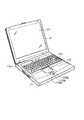
図1は本発明の実施形態に於ける情報処理装置の外観構成を示す斜視図であり、ここでは、ノートブック型パーソナルコンピュータを例に示している。
【0014】
この図1に示す、本発明の実施形態によるコンピュータは、コンピュータ本体11と、ディスプレイユニット12とから構成されている。ディスプレイユニット12には、LCDからなる主表示装置121が組み込まれている。このディスプレイユニット12は、コンピュータ本体11に対して解放位置と閉塞位置との間を回動自在に取り付けられている。コンピュータ本体11は薄い箱形の筐体を有しており、その筐体上面には、コンピュータ本体11の電源をオン/オフするためのパワーボタン114、キーボード111等が配置され、キーボード111の手前の筐体部分上面にはアームレストが形成されている。このアームレストのほぼ中央部には、タッチスクリーン機能を有する副表示装置(cPadデバイス)112が設けられる。この副表示装置112は、上記主表示装置121より表示面が小さいLCD等の表示パネルとダブレットとを一体に設けた表示一体型のポインティングデバイスを構成するもので、レフト(左)ボタン113a、ライト(右)ボタン113b、およびミドル(中)ボタン113cとともに上記アームレストを形成する筐体上面に配置されている。
【0015】
図2は上記図1に示したコンピュータのシステム構成を示すブロック図である。このコンピュータには、図示するように、CPU201、ホストブリッジ202、主メモリ203、グラフィクスコントローラ204、PCI−ISAブリッジ206、I/Oコントローラ207、ハードディスクドライブ(HDD)208、CD−ROMドライブ209、USBコントローラ210、エンベデッドコントローラ/キーボードコントローラIC(EC/KBC)211、および電源コントローラ213等が設けられている。
【0016】
USBコントローラ210には、上記した副表示装置(サブディスプレイ)112が接続されている。この副表示装置112は、タッチパッド112aと、表示部112bと、バックライト112cとが一体化されてタッチスクリーン機能を実現し、レフト(左)ボタン113a、ライト(右)ボタン113b、およびミドル(中)ボタン113cを含んで構成される。
【0017】
CPU201は、本コンピュータの動作を制御するために設けられたもので、ハードディスクドライブ(HDD)208から主メモリ203にロードされたオペレーティングシステム(OS)、およびアプリケーションプログラム、ユーティリティプログラム等を実行する。この実施形態では、上記副表示装置112の制御プログラム(図3参照)およびマウスドライバと連繋して後述する図5に示すような副表示装置112上での1タッチ操作によるマウスポインタの位置合わせ処理機能を実現する入出力プログラムの処理を実行する。
【0018】
ホストブリッジ202はCPU201のローカルバスとPCIバス1との間を双方向で接続するブリッジデバイスである。グラフィクスコントローラ204はビデオRAM(VRAM)を備え、専用ディスプレイドライバの制御の下に本コンピュータのディスプレイモニタとして使用される主表示装置121を制御する。I/Oコントローラ207はハードディスクドライブ(HDD)208、CD−ROMドライブ209等を制御する。PCI−ISAブリッジ206はPCIバス1とISAバス2を双方向で接続するブリッジデバイスであり、ここには例えばシステムタイマ、DMAコントローラ、割り込みコントローラなどの各種システムデバイスも内蔵されている。
【0019】
エンベデッドコントローラ/キーボードコントローラIC(EC/KBC)211は、電力管理のためのエンベデッドコントローラ(EC)とキーボード111を制御するためのキーボードコントローラ(KBC)とが集積された1チップマイクロコンピュータである。このエンベデッドコントローラ/キーボードコントローラIC(EC/KBC)211は、電源コントローラ213と協同して、ユーザによるパワーボタン114の操作に応じて本コンピュータをパワーオン/パワーオフする機能を有している。
【0020】
図3は本発明の実施形態に於ける副表示装置112の機能構成要素を示す図であり、ここでは、副表示装置112の機能を設定する設定テーブル301、設定テーブル301の内容に従い副表示装置112の機能制御を行う制御プログラム302、副表示装置112と制御プログラム302との間でやり取りされる情報の入出力を制御を行うインターフェース303、GUIにより設定テーブル301を作成する設定プログラム311、制御プログラム302の指示に従い各種の処理を実行する実行手段312、および副表示装置112を構成要素としている。この実施形態では、上記実行手段312が、ミドルボタン113cの操作に伴い、副表示装置112の機能を、マウス設定プログラムの制御に従うポインティング機能、即ち副表示装置112上で指を摺動させることで主表示装置121上のマウスポインタを移動可能なポインティング操作入力モード(デフォルトモード)と、仮想画面上での1タッチ操作によるマウスポインタの位置合わせ機能(マウスポインタタッチ操作入力モード)とを切り替える(図5参照)。
【0021】
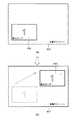
図4は、上記実施形態に於ける、コンピュータ本体11で扱う仮想画面と、実表示画面との関係を示す図である。尚、この実施形態では、主表示装置121に表示される、主操作画面領域を含んだデスクトップ全体画面を仮想画面若しくは仮想スクリーンと称し、主表示装置121に現在表示されている実表示画面を主操作画面と称している。
【0022】
コンピュータ本体11に設けられた、ディスプレイユニット12には、本コンピュータのディスプレイモニタとして使用される、LCDからなるディスプレイスクリーン(メインディスプレイ)121が組み込まれている。
【0023】
この主表示装置121には、仮想画面(仮想スクリーン)401上に割り当てられた表示エリア402内の画面イメージが主操作画面として表示される。この際の表示エリア402のサイズ(解像度)は、主表示装置121の表示画面(実表示画面)のサイズ(解像度)と同じである。すなわち、仮想スクリーン401全体の画面イメージのうち、表示エリア402内の画面イメージのみが主操作画面として主表示装置121に表示される。この意味で、表示エリア402内の画面イメージは、主表示装置121の実表示画面の画面イメージであるということができる。表示エリア402の位置は、図4の点線で示すように、パニング操作で、仮想スクリーン401内の任意の位置および範囲に設定することができる。この実施形態では、副表示装置112を用いた仮想画面上での1タッチ操作によるマウスポインタの位置合わせ操作時に於いて、マウスポインタの移動先(位置合わせ先)が主表示装置121に表示されている主操作画面の表示範囲外であるとき、入出力プログラム制御の下にパニング処理が行われる。この実施形態では、マウスポインタが移動する以前の主操作画面とマウスポインタとの相対位置関係を保つように、仮想画面とマウスポインタの移動先との相対位置をもとに、主操作画面の表示範囲を設定するパニング処理が行われる。これによって、主操作画面の表示範囲が切り替わっても(パニングしても)当該画面上でのマウスポインタ位置を容易に認識でき、マウスポインタの位置合わせ操作をより容易かつ迅速に行うことができる。
【0024】
図5は本発明の実施形態に於ける操作処理手順を示すフローチャートであり、副表示装置112の制御プログラム302とマウスドライバと入出力制御プログラムとの連繋処理により実現される。この処理では、副表示装置112を用いた仮想画面上での1タッチ操作によるマウスポインタの位置合わせ機能を実現するもので、ここでは一例として副表示装置11がポインティング操作入力モードにあるとき、副表示装置112に設けられたミドルボタン113cを操作することにより、副表示装置112を用いた仮想画面上での1タッチ操作によるマウスポインタの位置合わせ機能を実現するマウスポインタタッチ操作入力モードに切り替わる。
【0025】
図6および図7はそれぞれ本発明の実施形態に於けるマウスポインタの位置合わせ操作を説明するための図である。図6は副表示装置112上での操作例を示し、図7はその操作に伴う仮想画面(仮想スクリーン)上での主操作画面の表示遷移を示している。
【0026】
図6に於いては、副表示装置112が、マウス設定プログラムの制御に従う通常のポインティング機能、即ち副表示装置112上で指を摺動させることで主表示装置121上のマウスポインタを移動可能なポインティング操作入力モード(デフォルトモード)にある際に、図(a)に示すように、副表示装置112に設けられたミドルボタン113cを操作すると、副表示装置112が仮想画面上での1タッチ操作によるマウスポインタの位置合わせ機能(マウスポインタタッチ操作入力モード)に切り替わり、図(b)に示すように、副表示装置112に仮想画面のイメージが表示される。この実施形態では、マウスポインタの移動(位置合わせ)前に主表示装置121に表示されている主操作画面の領域(数値1を囲ったエリア)65と、当該領域65内に於けるマウスポインタ66の位置とを明示した仮想画面のイメージを副表示装置112に表示する。この仮想画面のイメージ表示状態下に於いて、指タッチ操作により、ある一点をタッチ操作することにより、マウスポインタの移動先(位置合わせ先)を指示できる。この際のタッチ操作位置(マウスポインタの移動先指示位置)の一例を図6に符号TPで示している。
【0027】
図7に於いては、上記図6に示すマウスポインタの位置合わせ操作(タッチ操作)で、主表示装置121に表示されている表示範囲を超えた仮想画面空間上が指示された際の主表示装置121の表示遷移例を示している。この実施形態では、マウスポインタの移動先が上記主表示装置に表示されている主操作画面の表示範囲外であるとき、上記マウスポインタが移動する以前の上記主操作画面と上記マウスポインタとの相対位置関係を保つように、上記仮想画面と上記マウスポインタの移動先との相対位置をもとに上記主操作画面の表示範囲を設定する処理で、主表示装置121に表示される主操作画面上でのマウスポインタの表示位置が設定(決定)される。
【0028】
ここで、上記各図を参照して本発明の実施形態に於ける動作を説明する。
【0029】
システムの起動後に於いては、副表示装置112が、マウス設定プログラムの制御に従う通常のポインティング機能、即ち副表示装置112上で指を摺動させることで主表示装置121上のマウスポインタを移動可能なポインティング操作入力モードとなっており、この際は、図6(a)に示すように、マウスポインティング操作画面として機能している(図5ステップS101)。
【0030】
この状態で、副表示装置112に設けられたミドルボタン113cが操作されると(図5ステップS102 Yes,S103 Yes)、副表示装置112の動作モード(機能)が、図6(a)に示すポインティング操作入力モードから、図6(b)に示すように、仮想画面(デスクトップ全体画面)上での1タッチ操作によるマウスポインタの位置合わせ機能を実現するマウスポインタタッチ操作入力モードに切り替わる(図5ステップS104)。この実施形態では、マウスポインタの位置合わせ前に主表示装置121に表示されている主操作画面の領域(数値1を囲ったエリア)65と、当該主操作画面の領域65内に於けるマウスポインタ66の位置とを明示した仮想画面のイメージが副表示装置112に表示される。
【0031】
この副表示装置112に仮想画面(デスクトップ全体画面)されている状態で、当該画面上のある一点がタッチ操作されると(図5ステップS105 No,S107 Yes)、そのタッチ操作位置(TP)が、副表示装置112に現在表示されている主操作画面の領域65内(数値1を囲ったエリア内)である際(図5ステップS108 Yes)は、主表示装置121の表示範囲に変化は無く(パニング処理を行わずに)、主表示装置121に表示されているマウスポインタを上記指タッチ操作位置(TP)に従う移動先(位置合わせ先)に移す(図5ステップS110)。また、上記図6に示すマウスポインタの位置合わせ操作(タッチ操作)で、主表示装置121に表示されている表示範囲を超えた仮想画面空間上が指示された際、即ちマウスポインタの移動先(位置合わせ先)が、現在、主表示装置121に表示されている主操作画面の表示範囲外であるときは、上記マウスポインタが移動する以前の主操作画面とマウスポインタとの相対位置関係を保つように、仮想画面とマウスポインタの移動先との相対位置をもとに主操作画面の表示範囲を設定する処理により、主表示装置121に表示される主操作画面上でのマウスポインタの表示位置が設定される。ここで設定された主操作画面の表示範囲およびマウスポインタの表示位置に従い、主表示装置121に主操作画面とマウスポインタが表示される(図5ステップS109,S110)。この際の主表示装置121に表示される、仮想画面内での主操作画面の遷移例を図7に示している。
【0032】
上記した副表示装置112上でのタッチ操作によるマウスポインタの位置合わせ後、再びミドルボタン113cが操作されると(図5ステップS105 Yes,S106 Yes)、副表示装置112の動作モード(機能)が、仮想画面上での1タッチ操作によるマウスポインタの位置合わせ機能を実現するマウスポインタタッチ操作入力モードから、上記した通常のポインティング操作入力モードに切り替わる(デフォルトモードに復帰する)。このように、ミドルボタン113cを操作する度に、上記した通常のポインティング操作入力モードと、マウスポインタタッチ操作入力モードとが交互に選択される。尚、上記通常のポインティング操作入力モード状態にあるとき、ミドル(中)ボタン113c以外のボタンが操作された際は、そのボタンに予め定められた割り付けられた処理が実行される。尚、上記処理内で、ミドルボタン113c以外のボタン(113a,113b)が操作された際は、その操作されたボタン(113a,113b)に割り付けられた機能の処理が実行される(図4ステップS111)。
【0033】
このように、副表示装置112に、主表示装置121に表示される主操作画面を含むデスクトップ全体の画面イメージをマウスポインタの位置をタッチ操作で指示する操作画面として表示することで、マウスポインタの位置精度を上げた状態で、デスクトップ上の広い範囲に亘ってマウスポインタを容易かつ迅速に移動(位置合わせ)操作できる。
【0034】
上記した実施形態では、副表示装置112に、主表示装置121に表示される主操作画面を含むデスクトップ全体の画面イメージをマウスポインタの位置をタッチ操作で指示する操作画面として表示しているが、例えば副表示装置112に、主表示装置121に表示される主操作画面全体のデスクトップ画面イメージをマウスポインタの位置をタッチ操作で指示する操作画面として表示する構成としてもよい。この際は、例えば主表示装置121に表示された主操作画面上に於いて、対向する端点の近傍間等、主操作画面上の離れた場所間でのマウスポインタの位置の合わせ操作に効果を発揮する。
【0035】
また、上記実施形態では、上記副表示装置112の動作モード切り替え(通常のポインティング操作入力モード/マウスポインタタッチ操作入力モード)をミドル(中)ボタン113cの操作で行っているが、例えば、タッチ操作によるマウスポインタの位置合わせ処理終了後、自動的に通常のポインティング操作入力モードに戻す(デフォルトモードに復帰させる)ことも可能である。
【0036】
また、上記実施形態では、マウスポインタの移動先(位置合わせ先)が、現在、主表示装置121に表示されている主操作画面の表示範囲外であるとき、上記マウスポインタが移動する以前の主操作画面とマウスポインタとの相対位置関係を保つように、仮想画面とマウスポインタの移動先との相対位置をもとに主操作画面の表示範囲を設定していたが、例えば、常に、主操作画面上の予め設めた位置(例えば中央、コーナー等)に表示することも可能である。
【0037】
【発明の効果】
以上詳記したように本発明によれば、ポインタの位置精度を上げた状態でデスクトップ上の広い範囲に亘ってポインタを容易かつ迅速に移動(位置合わせ)操作できる。
【図面の簡単な説明】
【図1】本発明の実施形態に於ける情報処理装置の外観構成を示す斜視図。
【図2】上記実施形態に於けるコンピュータのシステム構成を示すブロック図。
【図3】上記実施形態に於ける副表示装置の機能構成要素を示す図。
【図4】上記実施形態に於ける仮想画面(デスクトップ全体画面)と実表示画面との関係を示す図。
【図5】上記実施形態に於ける操作処理手順を示すフローチャート。
【図6】上記実施形態に於けるマウスポインタの位置合わせ操作を説明するための副表示装置上での操作例を示す図。
【図7】上記実施形態に於けるマウスポインタの位置合わせ操作を説明するための仮想画面(仮想スクリーン)上での主操作画面の表示遷移を示す図。
【符号の説明】
1…PCIバス、2…ISAバス、11…コンピュータ本体、12…ディスプレイユニット、65…副表示装置に表示された主操作画面のイメージ、66…副表示装置にひひされたマウスポインタ、111…キーボード(KB)、112…副表示装置(cPadデバイス)、112a…タッチパッド、112b…表示部、112c…バックライト、113a…レフトボタン、113b…ライトボタン、113c…ミドルボタン、114…パワーボタン、121…主表示装置(メインディスプレイ)、201…CPU、202…ホストブリッジ、203…主メモリ、204…グラフィクスコントローラ、206…PCI−ISAブリッジ、207…I/Oコントローラ、208…ハードディスクドライブ(HDD)、209…CD−ROMドライブ、210…USBコントローラ、211…エンベデッドコントローラ/キーボードコントローラIC(EC/KBC)、213…電源コントローラ、301…設定テーブル、302…制御プログラム、303…インターフェース、311…設定プログラム、312…実行手段、401…仮想画面(仮想スクリーン)、402…主操作画面となる表示エリア。[0001]
BACKGROUND OF THE INVENTION
The present invention relates to an information processing apparatus including a display device that displays an operation screen that can be operated using a pointer, and a pointer operation method.
[0002]
[Prior art]
In recent years, notebook-type or laptop-type portable personal computers are provided with a pointing device that enables, for example, a mouse pointing operation, a numeric keypad input operation, and the like (see, for example, Patent Document 1).
[0003]
In this type of conventional personal computer, when the mouse pointer is moved to a desired position on the real display screen or the virtual screen, conventionally, the pointer operation is a sliding operation on the touch pad, It was done by moving the mouse, rolling the trackball, operating the cursor keys on the keyboard.
[0004]
[Patent Document 1]
JP2000-339097
[0005]
[Problems to be solved by the invention]
The conventional mouse pointer operation means described above functions effectively in a narrow range where the operation range is limited. For example, the mouse can be used for a wide range on the screen with the movement amount pitch set finely. When moving the pointer, it is necessary to repeatedly operate the above-described operation device a plurality of times, which causes a problem in operability. At this time, the number of operations can be reduced by increasing the movement speed of the mouse pointer (by finely setting the movement amount pitch) and setting the pointer movement distance to the device operation to be large. However, there is a problem that the operability is remarkably deteriorated. In addition, when only a part of the desktop is displayed on the display device and the position where the mouse pointer is set is not displayed on the display device, in addition to the above operation, a panning operation for displaying the position where the mouse pointer is set (Operation to move the display range displayed on the actual display screen within the virtual screen) is required, and there is a problem that the operability is further deteriorated.
[0006]
The present invention has been made in view of the above circumstances, and an information processing apparatus that realizes a function that allows a pointer to be moved (positioned) easily and quickly over a wide range on the desktop in a state where the position accuracy of the pointer is increased, and An object is to provide a method for operating a pointer.
[0007]
[Means for Solving the Problems]
The present invention uses the above-described pointing device in which a display panel is integrally incorporated in the pointing device, and the pointing device is provided in a device main body, a keyboard housing or the like, on the display panel of the pointing device. A simple image of the virtual screen (the entire desktop screen) is displayed, and the pointing operation is performed with the simple image of the virtual screen displayed on the display panel, and the operation is reflected on the display screen of the display device of the device main body. It is characterized by having a configuration.
[0008]
That is, according to the present invention, in an information processing apparatus such as a personal computer, a first display device that displays amain operation screen, a second display devicethat includes a touch pad, anda pointer that can be operated by the touch pad. Is displayedon the main operation screen, and the control means displaysonthe second display device an operation screen having a virtual screen including the main operation screen as an operation range of the touchpad. And a means for setting a display range of the main operation screen as the pointer moves in a virtual screen including the main operation screen .
[0009]
In the information processing apparatus, the second display device is operated with an image of the entire screen displayed on the first display device or a virtual screen image exceeding the display range of the first display device. By displaying it as a screen, the pointer can be moved (positioned) easily and quickly over a wide range on the desktop with the position accuracy of the pointer raised.
[0010]
Further, when the movement destination of the pointer is outside the display range of the screen displayed on the first display device, the operation screen and the pointer displayed on the first display device before the pointer moves. By setting the display range of the operation screen displayed on the first display device based on the relative position between the virtual screen and the movement destination of the pointer so as to maintain the relative positional relationship with Even if the display range of the screen displayed on one display device is switched, the position of the pointer on the screen can be easily recognized, and the pointer positioning operation can be performed more easily and quickly.
[0011]
Further, the position of the pointer is displayed by displaying an image of a virtual screen in which the display range of the screen displayed on the first display device and the position of the pointer on the screen are clearly displayed on the second display device as an operation screen. The alignment operation can be performed more easily and quickly.
[0012]
DETAILED DESCRIPTION OF THE INVENTION
Hereinafter, embodiments of the present invention will be described with reference to the drawings.
[0013]
FIG. 1 is a perspective view showing an external configuration of an information processing apparatus according to an embodiment of the present invention. Here, a notebook personal computer is taken as an example.
[0014]
The computer according to the embodiment of the present invention shown in FIG. 1 includes a computer main body 11 and a
[0015]
FIG. 2 is a block diagram showing the system configuration of the computer shown in FIG. As shown, the computer includes a
[0016]
The
[0017]
The
[0018]
The
[0019]
The embedded controller / keyboard controller IC (EC / KBC) 211 is a one-chip microcomputer in which an embedded controller (EC) for power management and a keyboard controller (KBC) for controlling the
[0020]
FIG. 3 is a diagram showing functional components of the
[0021]
FIG. 4 is a diagram showing the relationship between the virtual screen handled by the computer main body 11 and the actual display screen in the embodiment. In this embodiment, the entire desktop screen including the main operation screen area displayed on the
[0022]
A
[0023]
On the
[0024]
FIG. 5 is a flowchart showing an operation processing procedure according to the embodiment of the present invention, and is realized by a linkage process of the
[0025]
6 and 7 are diagrams for explaining the mouse pointer positioning operation in the embodiment of the present invention. FIG. 6 shows an operation example on the
[0026]
In FIG. 6, the
[0027]
In FIG. 7, the main display when the mouse pointer alignment operation (touch operation) shown in FIG. 6 is instructed on the virtual screen space that exceeds the display range displayed on the
[0028]
Here, the operation in the embodiment of the present invention will be described with reference to the respective drawings.
[0029]
After the system is started, the
[0030]
In this state, when the
[0031]
When a certain point on the screen is touch-operated while the virtual screen (entire desktop screen) is displayed on the sub display device 112 (step S105 No, S107 Yes in FIG. 5), the touch operation position (TP) is set. When it is in the
[0032]
When the
[0033]
As described above, the screen image of the entire desktop including the main operation screen displayed on the
[0034]
In the above-described embodiment, the screen image of the entire desktop including the main operation screen displayed on the
[0035]
In the above-described embodiment, the operation mode switching (normal pointing operation input mode / mouse pointer touch operation input mode) of the
[0036]
In the above embodiment, when the movement destination (positioning destination) of the mouse pointer is currently outside the display range of the main operation screen displayed on the
[0037]
【The invention's effect】
As described above in detail, according to the present invention, it is possible to easily and quickly move (align) the pointer over a wide range on the desktop with the position accuracy of the pointer being raised.
[Brief description of the drawings]
FIG. 1 is a perspective view showing an external configuration of an information processing apparatus according to an embodiment of the present invention.
FIG. 2 is a block diagram showing a system configuration of a computer in the embodiment.
FIG. 3 is a diagram showing functional components of a sub display device in the embodiment.
FIG. 4 is a diagram showing a relationship between a virtual screen (entire desktop screen) and an actual display screen in the embodiment.
FIG. 5 is a flowchart showing an operation processing procedure in the embodiment.
FIG. 6 is a diagram showing an operation example on the sub display device for explaining the mouse pointer positioning operation in the embodiment.
FIG. 7 is a diagram showing a display transition of a main operation screen on a virtual screen (virtual screen) for explaining a mouse pointer positioning operation in the embodiment.
[Explanation of symbols]
DESCRIPTION OF
Claims (16)
Translated fromJapaneseタッチパッドを備えた第2の表示装置と、
前記タッチパッドにより操作可能なポインタを前記主操作画面上に表示する制御手段とを具備し、
前記制御手段は、前記主操作画面を含む仮想画面を前記タッチパッドの操作範囲とした操作画面を前記第2の表示装置に表示し、前記主操作画面を含む仮想画面内で前記ポインタの移動に伴い前記主操作画面の表示範囲を設定する手段を具備したことを特徴とする情報処理装置。A first display device for displaying amain operation screen;
A second display device comprising atouchpad ;
Control meansfor displayinga pointer operable by the touchpad on the main operation screen ,
The control meansdisplays an operation screen having the virtual screen including the main operation screen as an operation range of the touchpad on the second display device, and moves the pointer in the virtual screen including the main operation screen. Accordingly , an information processing apparatuscomprising means for setting a display range of the main operation screen .
前記制御手段は、前記主操作画面を含む仮想画面を前記タッチパッドの操作範囲とした操作画面を前記第2の表示装置に表示し、前記主操作画面を含む仮想画面内で前記ポインタの移動に伴い前記主操作画面の表示範囲を設定することを特徴とするポインタの操作方法。An apparatus comprising: a first display device that displays a main operation screen; a second display device that includes a touch pad; and a control unit that displays a pointer operable by the touch pad on the main operation screen. A pointer operation method,
The control means displays an operation screen having the virtual screen including the main operation screen as an operation range of the touchpad on the second display device, and moves the pointer in the virtual screen including the main operation screen. Accordingly, a display range of the main operation screen is set .
Priority Applications (3)
| Application Number | Priority Date | Filing Date | Title |
|---|---|---|---|
| JP2003024419AJP3811128B2 (en) | 2003-01-31 | 2003-01-31 | Information processing apparatus and pointer operating method |
| US10/767,267US7292206B2 (en) | 2003-01-31 | 2004-01-30 | Information processing apparatus and method of operating pointing device |
| EP04002168AEP1450239A3 (en) | 2003-01-31 | 2004-01-30 | Information processing apparatus and method of operating pointing device |
Applications Claiming Priority (1)
| Application Number | Priority Date | Filing Date | Title |
|---|---|---|---|
| JP2003024419AJP3811128B2 (en) | 2003-01-31 | 2003-01-31 | Information processing apparatus and pointer operating method |
Publications (2)
| Publication Number | Publication Date |
|---|---|
| JP2004234504A JP2004234504A (en) | 2004-08-19 |
| JP3811128B2true JP3811128B2 (en) | 2006-08-16 |
Family
ID=32732885
Family Applications (1)
| Application Number | Title | Priority Date | Filing Date |
|---|---|---|---|
| JP2003024419AExpired - Fee RelatedJP3811128B2 (en) | 2003-01-31 | 2003-01-31 | Information processing apparatus and pointer operating method |
Country Status (3)
| Country | Link |
|---|---|
| US (1) | US7292206B2 (en) |
| EP (1) | EP1450239A3 (en) |
| JP (1) | JP3811128B2 (en) |
Families Citing this family (22)
| Publication number | Priority date | Publication date | Assignee | Title |
|---|---|---|---|---|
| JP2006146556A (en)* | 2004-11-19 | 2006-06-08 | Nintendo Co Ltd | Image display processing program and image display processing device |
| US8487910B2 (en)* | 2005-05-02 | 2013-07-16 | Smart Technologies Ulc | Large scale touch system and methods for interacting with same |
| JP2007011459A (en)* | 2005-06-28 | 2007-01-18 | Konica Minolta Business Technologies Inc | Image formation device |
| JP2007158919A (en)* | 2005-12-07 | 2007-06-21 | Fujifilm Corp | Image display device and image display method |
| US20070165370A1 (en)* | 2006-01-13 | 2007-07-19 | Yao-Shih Leng | Portable computer with multiple monitors |
| EP1832965A1 (en)* | 2006-03-10 | 2007-09-12 | E-Lead Electronic Co., Ltd. | Composite cursor input method |
| US20100107067A1 (en)* | 2008-10-27 | 2010-04-29 | Nokia Corporation | Input on touch based user interfaces |
| US20100107116A1 (en)* | 2008-10-27 | 2010-04-29 | Nokia Corporation | Input on touch user interfaces |
| JP5540344B2 (en) | 2008-10-30 | 2014-07-02 | シャープ株式会社 | Electronic device, menu selection method, menu selection program |
| JP5154368B2 (en)* | 2008-10-31 | 2013-02-27 | シャープ株式会社 | COMMUNICATION DEVICE AND ITS CONTROL METHOD |
| JP2010108448A (en)* | 2008-10-31 | 2010-05-13 | Sharp Corp | Data transmission support device, electronic equipment, and method of controlling the data transmission support device |
| JP5370374B2 (en)* | 2009-02-13 | 2013-12-18 | 富士通モバイルコミュニケーションズ株式会社 | Information processing device |
| US9703411B2 (en) | 2009-04-30 | 2017-07-11 | Synaptics Incorporated | Reduction in latency between user input and visual feedback |
| TWI408671B (en)* | 2009-05-15 | 2013-09-11 | Wistron Corp | Portable electronic device |
| US10705692B2 (en) | 2009-05-21 | 2020-07-07 | Sony Interactive Entertainment Inc. | Continuous and dynamic scene decomposition for user interface |
| WO2011037558A1 (en) | 2009-09-22 | 2011-03-31 | Apple Inc. | Device, method, and graphical user interface for manipulating user interface objects |
| US9310907B2 (en) | 2009-09-25 | 2016-04-12 | Apple Inc. | Device, method, and graphical user interface for manipulating user interface objects |
| US8832585B2 (en) | 2009-09-25 | 2014-09-09 | Apple Inc. | Device, method, and graphical user interface for manipulating workspace views |
| JP2011134278A (en)* | 2009-12-25 | 2011-07-07 | Toshiba Corp | Information processing apparatus and pointing control method |
| US8797283B2 (en) | 2010-11-22 | 2014-08-05 | Sony Computer Entertainment America Llc | Method and apparatus for performing user-defined macros |
| US8907903B2 (en) | 2011-01-13 | 2014-12-09 | Sony Computer Entertainment America Llc | Handing control of an object from one touch input to another touch input |
| KR20140134940A (en)* | 2013-05-15 | 2014-11-25 | 삼성전자주식회사 | Mobile terminal and method for controlling touch screen and system threefor |
Family Cites Families (11)
| Publication number | Priority date | Publication date | Assignee | Title |
|---|---|---|---|---|
| DE19543377A1 (en)* | 1995-11-21 | 1997-05-22 | Philips Patentverwaltung | Method and arrangement for displaying images from an image group |
| US5841435A (en)* | 1996-07-26 | 1998-11-24 | International Business Machines Corporation | Virtual windows desktop |
| US5923307A (en)* | 1997-01-27 | 1999-07-13 | Microsoft Corporation | Logical monitor configuration in a multiple monitor environment |
| JP2000339097A (en) | 1998-12-16 | 2000-12-08 | Sony Corp | Information processor, its controlling method and recording medium |
| US6407779B1 (en)* | 1999-03-29 | 2002-06-18 | Zilog, Inc. | Method and apparatus for an intuitive universal remote control system |
| JP2000279399A (en) | 1999-03-31 | 2000-10-10 | Fuji Photo Film Co Ltd | Method and device for measuring radiation picture |
| KR100648231B1 (en)* | 1999-10-19 | 2006-11-24 | 삼성전자주식회사 | A portable computer comprising the pointing device using an auxiliary liquid crystal display panel having a touch screen and a method thereof |
| JP5039911B2 (en)* | 2000-10-11 | 2012-10-03 | インターナショナル・ビジネス・マシーンズ・コーポレーション | Data processing device, input / output device, touch panel control method, storage medium, and program transmission device |
| US7730401B2 (en)* | 2001-05-16 | 2010-06-01 | Synaptics Incorporated | Touch screen with user interface enhancement |
| US20050024341A1 (en)* | 2001-05-16 | 2005-02-03 | Synaptics, Inc. | Touch screen with user interface enhancement |
| JP2004127048A (en)* | 2002-10-04 | 2004-04-22 | Toshiba Corp | Information processing equipment |
- 2003
- 2003-01-31JPJP2003024419Apatent/JP3811128B2/ennot_activeExpired - Fee Related
- 2004
- 2004-01-30USUS10/767,267patent/US7292206B2/enactiveActive
- 2004-01-30EPEP04002168Apatent/EP1450239A3/ennot_activeWithdrawn
Also Published As
| Publication number | Publication date |
|---|---|
| EP1450239A3 (en) | 2007-11-07 |
| US20040239621A1 (en) | 2004-12-02 |
| EP1450239A2 (en) | 2004-08-25 |
| JP2004234504A (en) | 2004-08-19 |
| US7292206B2 (en) | 2007-11-06 |
Similar Documents
| Publication | Publication Date | Title |
|---|---|---|
| JP3811128B2 (en) | Information processing apparatus and pointer operating method | |
| JP4163713B2 (en) | Information processing apparatus and touchpad control method | |
| JP3892760B2 (en) | Information processing device | |
| JP3788942B2 (en) | Information processing apparatus and computer operation support method | |
| JP2003330591A (en) | Information processing apparatus and computer operation method | |
| JP4956644B2 (en) | Electronic device and input control method | |
| JP6162299B1 (en) | Information processing apparatus, input switching method, and program | |
| US20050138575A1 (en) | Information processing apparatus with display | |
| JP2003248550A (en) | Information processing device and computer operation function extension method | |
| JP2004234544A (en) | Information processing apparatus and operation window display method | |
| JP2006330912A (en) | Information processing apparatus and program | |
| JP2002259001A (en) | Method and device for window operation | |
| CN100447722C (en) | Cursor switching method in multi-display system and multi-display system | |
| JP2011159089A (en) | Information processor | |
| JP2011134127A (en) | Information processor and key input method | |
| US20040239645A1 (en) | Information processing apparatus and method of inputting character | |
| JPH0772976A (en) | Mouse input method on touch panel | |
| US11620015B2 (en) | Electronic device | |
| JP5458130B2 (en) | Electronic device and input control method | |
| JP2004246602A (en) | Information processor | |
| US20050262273A1 (en) | Information processing apparatus having data input devices and method of processing input data information | |
| JP2002244809A (en) | Method and device for freely changing moving speed of pointer, and minimization of touch pad | |
| US20040160413A1 (en) | Information processing apparatus | |
| JPH10198505A (en) | Personal computer equipment | |
| KR101118224B1 (en) | A realization method of mouse function buttom using keyboard in notebook computer |
Legal Events
| Date | Code | Title | Description |
|---|---|---|---|
| A977 | Report on retrieval | Free format text:JAPANESE INTERMEDIATE CODE: A971007 Effective date:20051212 | |
| A131 | Notification of reasons for refusal | Free format text:JAPANESE INTERMEDIATE CODE: A131 Effective date:20060221 | |
| A521 | Request for written amendment filed | Free format text:JAPANESE INTERMEDIATE CODE: A523 Effective date:20060421 | |
| TRDD | Decision of grant or rejection written | ||
| A01 | Written decision to grant a patent or to grant a registration (utility model) | Free format text:JAPANESE INTERMEDIATE CODE: A01 Effective date:20060523 | |
| A61 | First payment of annual fees (during grant procedure) | Free format text:JAPANESE INTERMEDIATE CODE: A61 Effective date:20060525 | |
| FPAY | Renewal fee payment (event date is renewal date of database) | Free format text:PAYMENT UNTIL: 20090602 Year of fee payment:3 | |
| FPAY | Renewal fee payment (event date is renewal date of database) | Free format text:PAYMENT UNTIL: 20100602 Year of fee payment:4 | |
| LAPS | Cancellation because of no payment of annual fees |