JP3810726B2 - Substrate heating control system and substrate heating control method - Google Patents
Substrate heating control system and substrate heating control methodDownload PDFInfo
- Publication number
- JP3810726B2 JP3810726B2JP2002291510AJP2002291510AJP3810726B2JP 3810726 B2JP3810726 B2JP 3810726B2JP 2002291510 AJP2002291510 AJP 2002291510AJP 2002291510 AJP2002291510 AJP 2002291510AJP 3810726 B2JP3810726 B2JP 3810726B2
- Authority
- JP
- Japan
- Prior art keywords
- temperature
- heater
- command value
- value
- mode
- Prior art date
- Legal status (The legal status is an assumption and is not a legal conclusion. Google has not performed a legal analysis and makes no representation as to the accuracy of the status listed.)
- Expired - Fee Related
Links
- 239000000758substrateSubstances0.000titleclaimsdescription72
- 238000010438heat treatmentMethods0.000titleclaimsdescription53
- 238000000034methodMethods0.000titleclaimsdescription33
- 238000009529body temperature measurementMethods0.000claimsdescription28
- 238000004519manufacturing processMethods0.000claimsdescription18
- 238000003860storageMethods0.000claimsdescription16
- 238000004364calculation methodMethods0.000claimsdescription12
- 230000004913activationEffects0.000claimsdescription11
- 238000005259measurementMethods0.000claimsdescription10
- 230000003247decreasing effectEffects0.000claimsdescription7
- 230000000630rising effectEffects0.000claimsdescription6
- 238000005268plasma chemical vapour depositionMethods0.000description13
- 239000010408filmSubstances0.000description8
- 230000000694effectsEffects0.000description7
- 239000004065semiconductorSubstances0.000description7
- 238000010586diagramMethods0.000description5
- 239000000126substanceSubstances0.000description5
- 238000012360testing methodMethods0.000description5
- 238000012546transferMethods0.000description5
- 230000015572biosynthetic processEffects0.000description4
- 238000012544monitoring processMethods0.000description3
- 238000004904shorteningMethods0.000description3
- 238000004891communicationMethods0.000description1
- 239000002131composite materialSubstances0.000description1
- 238000004590computer programMethods0.000description1
- 230000007423decreaseEffects0.000description1
- 238000000151depositionMethods0.000description1
- 230000008021depositionEffects0.000description1
- 238000009826distributionMethods0.000description1
- 238000012423maintenanceMethods0.000description1
- 239000000203mixtureSubstances0.000description1
- 238000002360preparation methodMethods0.000description1
- 230000002265preventionEffects0.000description1
- 238000012545processingMethods0.000description1
- 239000010409thin filmSubstances0.000description1
Images


Description
Translated fromJapanese【0001】
【発明の属する技術分野】
本発明は、プラズマCDV装置における基板加熱プロセスを管理する基板加熱制御システム及び基板加熱制御方法に関する。
【0002】
【従来の技術】
プラズマCVDは、多くの薄膜作成方法の中でも最も自由度が高く、無機物や有機物、複合物質等に至るまで、様々な物質の製膜に応用可能である。プラズマCVDにおいて制御可能なパラメータは、ガス組成、ガス流量、圧力、プラズマ出力、基板温度、基板バイアス等が存在し、膜堆積に関する物理現象や化学現象をこれらのパラメータによって独立に制御することが可能である。
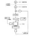
従来、プラズマCVD装置における基板温度制御方法として、図5に示す温度制御系が存在する。基板ヒータカバーにおけるTHC(ヒータカバー温度)の設定値と実際のTHCを比較してPID演算を行う。ことで、サイリスタが基板を加熱するヒータ本体へ出力する電力の最適値を算出し、この値に基づいてヒータ本体の温度制御を行う。また、温度モニタによってヒータ本体の温度を監視し、温度上限に関する条件リミットを設定しておくことでヒータ本体の暴走を防止することができる。
【0003】
しかし、上述の温度制御方法ではヒータ温度制御を行う系と、ヒータ温度の上限監視を行う系がそれぞれ独立して動作するため、温度管理効率が悪いという問題点がある。この問題点を解決するとともに、基板表面の温度管理を行う制御方法として、次に述べる方法が有効であることが知られている。すなわち、半導体加熱ステージである基板支持用電極の上方に半導体基板を載せて移動する移載部を設け、この移載部上に半導体基板を置く。移載部には加熱ヒータ及び熱電対が設けられており、熱電対によって測定された移載部上の半導体基板温度を温度コントローラに出力する。温度コントローラは、この温度情報に基づいて加熱ヒータの温度を制御する(特許文献1を参照)。
【0004】
【特許文献1】
特開平07−17683号公報
【0005】
【発明が解決しようとする課題】
しかし、プラズマCVD装置における基板加熱制御システムが大型化するに伴って、基板ヒータ本体の応答速度の低下が発生すると、温度整定にかかる時間が長時間化し、従来のような温度制御方法ではより大きな温度管理効率の低下を招くといった問題点がある。具体的には、大型の基板加熱制御システムにおける起動所要時間は10数時間に昇る場合がある。このため、プラズマCVD装置における基板加熱制御システムにおいては、温度管理における時間効率を従来以上に向上させることが望まれている。
【0006】
本発明は、このような事情を考慮してなされたものであり、その目的は、温度管理における時間効率を向上させることができる基板加熱制御システム及び基板加熱制御方法を提供することにある。
【0007】
【課題を解決するための手段】
この発明は上記の課題を解決すべくなされたもので、請求項1に記載の発明は、基板を加熱するヒータと、該ヒータを覆うヒータカバーと、前記ヒータの温度を測定し、出力するヒータ温度測定部と、前記ヒータカバーの温度を測定し、出力するヒータカバー温度測定部と、前記ヒータカバーの設定温度を入力する入力部と、前記ヒータカバーの温度設定値と、前記ヒータカバーの温度測定値とを受けて、該設定値と該測定値との差分変化を算出し、該差分変化に対するPIまたはPID演算を行い、第1の指令値を出力する第1のPID制御部と、予め設定された複数の温度管理モードを記憶する記憶部と、前記ヒータカバーの温度測定値に基づいて、前記温度管理モードを記憶部より読み出し、前記温度管理モードを切り替えるモード切替部と、前記温度管理モードで制御を行い、第2の指令値を出力する制御部と、前記制御部で算出された前記第2のヒータ温度指令値が予め設定された上限値を超えると当該第2の指令値を前記上限値に設定し、前記第2の指令値が予め設定された下限値を下回ると当該第2の指令値を前記下限値に設定する上下限リミッタと、前記ヒータの温度測定値と、前記第1の指令値または第2の指令値とを受けて、該測定値と該指令値との差分変化を算出し、該差分変化に対するPIまたはPID演算を行い、第3の指令値を出力する第2のPID制御部と、前記第3の指令値に基づいて、該ヒータへの電力制御を行うサイリスタと、を具備することを特徴とする。
【0009】
請求項2に記載の発明は、請求項1に記載の発明において、前記温度管理モードは、前記ヒータカバーの温度が予め設定された第1の閾値より低い場合、前記第1の指令値を無視し、昇温の初期段階で前記ヒータカバーに多めの熱量を投入して昇温時間を短縮するべく予め設定された昇温パターンに基づいて前記第2の指令値を決定する起動モードと、前記ヒータカバーの温度が予め設定された第2の閾値以上の場合、前記第1の指令値を前記第2の指令値とする待機モードまたは生産モードとからなることを特徴とする。
【0010】
請求項3に記載の発明は、請求項2に記載の発明において、前記温度管理モードは、ヒータの電源投入時に、前記ヒータカバーの温度が予め設定された第1の閾値より高い場合、予め設定された昇温パターンに基づいて前記第2の指令値を決定する再起動モードを
さらに有することを特徴とする。
【0011】
請求項4に記載の発明は、請求項2に記載の発明において、前記生産モードは、前記ヒータが設置される真空容器の真空度が予め決められた閾値より低い場合、前記第1のPID制御部における制御パラメータのゲインを増加させ、該真空度が該閾値より高い場合、前記第1のPID制御部における制御パラメータのゲインを減少させることを特徴とする。
【0012】
請求項5に記載の発明は、請求項2に記載の発明において、前記生産モードは、前記ヒータが設置される真空容器の真空度が予め決められた閾値より低い場合、前記第1のPID制御部における制御パラメータのゲインを増加させ、該真空度が該閾値より高い場合、前記第1のPID制御部における制御パラメータのゲインを減少させることを特徴とする。
【0013】
請求項6に記載の発明は、基板を加熱するヒータを覆うヒータカバーの設定温度を入力する過程と、前記ヒータカバーの温度を測定する過程と、前記ヒータカバーの温度設定値と前記ヒータカバーの温度測定値とに基づいて、該設定値と該測定値との差分変化を算出し、該差分変化に対するPIまたはPID演算を行い、第1の指令値を出力する過程と、前記ヒータカバーの温度測定値に基づいて、予め設定された複数の温度管理モードを記憶する記憶部より該温度管理モードを読み出し、前記温度管理モードを切り替える過程と、前記温度管理モードで制御を行い、第2の指令値を出力する過程と、前記制御部で算出された前記第2のヒータ温度指令値が予め設定された上限値を超えると当該第2の指令値を前記上限値に設定し、前記第2の指令値が予め設定された下限値を下回ると当該第2の指令値を前記下限値に設定する過程と、前記ヒータの温度を測定する過程と、前記ヒータの温度測定値と、前記第1の指令値または第2の指令値とに基づいて、該測定値と該指令値との差分変化を算出し、該差分変化に対するPIまたはPID演算を行い、第3の指令値を出力する過程と、前記第3の指令値に基づいて、前記ヒータへの電力制御を行う過程とを有することを特徴とする。
【0015】
請求項7に記載の発明は、請求項6に記載の発明において、前記温度管理モードは、前記ヒータカバーの温度が予め設定された第1の閾値より低い場合、予め設定された昇温パターンに基づいて前記第2の指令値を決定する起動モードと、前記ヒータカバーの温度が予め設定された第2の閾値以上の場合、前記第1の指令値を前記第2の指令値とする待機モードまたは生産モードとからなることを特徴とする。
【0016】
請求項8に記載の発明は、請求項7に記載の発明において、前記温度管理モードは、ヒータの電源投入時に、前記ヒータカバーの温度が予め設定された第1の閾値より高い場合、前記第1の指令値を無視し、昇温の初期段階で前記ヒータカバーに多めの熱量を投入して昇温時間を短縮するべく予め設定された昇温パターンに基づいて前記第2の指令値を決定する再起動モードをさらに有することを特徴とする。
【0017】
請求項9に記載の発明は、請求項7に記載の発明において、前記生産モードは、前記ヒータが設置される真空容器中に、前記基板が存在する場合、前記第1のPID制御部における制御パラメータのゲインを増加させ、前記基板が存在しない場合、前記第1のPID制御部における制御パラメータのゲインを減少させることを特徴とする。
【0018】
請求項10に記載の発明は、請求項7に記載の発明において、前記生産モードは、前記ヒータが設置される真空容器の真空度が予め決められた閾値より低い場合、前記第1のPID制御部における制御パラメータのゲインを増加させ、該真空度が該閾値より高い場合、前記第1のPID制御部における制御パラメータのゲインを減少させることを特徴とする。
【0019】
【発明の実施の形態】
以下、本発明の基板加熱制御システムの一実施形態について図面を参照して説明する。図1は、本実施形態における基板加熱制御システムの上位制御系の構成を示す構成図であり、図2は、その下位制御系の構成を示す構成図である。本実施形態における基板加熱制御システムは、ヒータ1と、ヒータカバー2と、ヒータ温度測定部3と、ヒータカバー温度測定部4と、入力部5と、PID制御部6と、記憶部7(図示せず)と、モード切替部8と、制御部9と、PID制御部10と、サイリスタ11と、リミッタ12と、パワー調整トリマ13とからなる。
【0020】
ヒータ1は、プラズマCVD装置内のチャンバー内に設けられており、サイリスタ11の電力制御によって基板を加熱する。ヒータカバー2は、ヒータ1を覆う形で設けられたカバーであり、ヒータカバー温度測定部4が内蔵または外装されている。ヒータ温度測定部3は、ヒータカバー温度測定部4と同様にヒータ1に内蔵または外装されたヒータ1の温度測定を行う熱電対等の温度測定器であって、PID制御部10と電気的に接続されている。ヒータカバー温度測定部4は、
ヒータ温度測定部3と同様にヒータカバー2の温度測定を行う熱電対等の温度測定器であって、PID制御部6と電気的に接続されている。入力部5は、基板加熱制御システムの管理者等がヒータカバーの設定温度を入力する入力装置である。
【0021】
PID制御部6は、ヒータカバーの温度設定値と、ヒータカバーの温度測定値との差分変化に基づくPID演算を行う。PLC(Programmable Logic Controller)による制御回路である。記憶部7は、上述のPLCに組み込まれたROM、RAM等の半導体メモリであり、複数の温度管理モードを記憶している。ここで、温度管理モードとは、プラズマCVD装置における基板加熱制御に関する一連の過程における、様々な状況に対応させたヒータカバーの温度設定値パターンであって、起動モード、待機モード、生産モード及び再起動モード等からなる。
【0022】
起動モードとは、図3及び図4に示す起動昇温プログラムによって制御される、ヒータ起動時の昇温モードであり、具体的には上述のPID制御部6の出力する指令値を用いずに、図4に示すヒータ1の温度設定値パターンによって制御される。昇温パターンは、基板ヒータ目標温度に対してオーバーシュートをしないこと及び起動昇温時間が極力短くなることを考慮して実際の基板加熱制御システムの加熱試験結果によって例えば図4のように定められる。
待機モードとは、起動モード終了後に移行する温度整定モードであり、真空容器を長時間高真空状態で保持させるために、上述のPID制御部6の出力する指令値によってPI制御を行う。
生産モードとは、真空容器にて製膜プロセスを実施する際の温度管理モードであって、真空容器中に基板が存在するか否か、或いは真空容器の真空度が予め決められた閾値より高いか低いかを判定することにより、PID制御部6における制御パラメータを変化させる。すなわち、真空容器中に、基板が存在する場合、PID制御部6における制御パラメータのゲインを増加させ、基板が存在しない場合、制御パラメータのゲインを減少させる。また、真空容器の真空度が予め決められた閾値より低い場合、PID制御部6における制御パラメータのゲインを増加させ、真空度が閾値より高い場合、制御パラメータのゲインを減少させる。
【0023】
モード切替部8は、上述のヒータカバー2の温度測定値に基づいて、温度管理モードを記憶部7より読み出し、温度管理モードを切り替える制御器であって、PID制御部6と同様、PLC上の制御回路である。
制御部9は、PID制御部6等と同様に、PLC上の制御回路であって、モード切替部8の出力する温度管理モードに基づいて、ヒータ温度を設定し、これを指令値として出力する。
加算器14は、同様にPLC上の制御回路でであって、PID制御部6の出力がOFFの時は制御部9の出力する指令値を、制御部6の出力がOFFの時は制御部9の出力する指令値をリミッタ12に出力する。
リミッタ12は、制御部9の指令値が、予め設定された上限値を超えた場合これを上限値に修正し、同様に設定された下限値を超えた場合これを下限値に修正する。この上限値及び下限値はヒータ1の設定可能レンジ等によって定めることができる。
PID制御部10は、PID制御部6等と同様に、ヒータ1の温度設定値と、ヒータ1の温度測定値との差分変化に基づくPID演算を行う。PLC上の制御回路である。
サイリスタ11は、PID制御部10の指令値に基づいてヒータ1への電力制御を行うパワー半導体デバイスである。
パワー調整トリマ13は、サイリスタ11のパワー調整を行う可変抵抗器である。
【0024】
以下、本実施形態の基板加熱制御システムの動作について図面を参照して説明する。図3は、ヒータ1の電源投入から起動までの流れを示すフローチャートである。また、図4はヒータ1の設定温度と、ヒータカバー2の測定温度の時系列的関係を示す温度グラフである。
【0025】
基板加熱制御システムの管理者等がヒータカバー2の設定温度を入力部5より入力し、ヒータ1の電源を投入すると(図3のステップ1)、ヒータカバー温度測定部4がヒータカバー2の温度の測定値をPID制御部6に出力する。このとき、図3、4に示すようにヒータカバー2の温度が20℃であって所定の閾値よりも低い(ステップS2でYes)ことから、モード切替部8は記憶部7より上述の起動モードに対応する起動昇温プログラムを読み出してこれをセットする(ステップS3)。ここで、ヒータカバーの温度の閾値は、実際の基板加熱制御システムの加熱試験結果によって定められる数値α(後述する)によって決定する。例えば、閾値はヒータカバー設定温度とαの差で表される。
【0026】
起動昇温プログラムのセットを受けて、PID制御部6はOFFされる。そして制御部9は、このプログラムに従って図4に示す昇温パターンを実行する。すなわち、制御部9は、まずヒータの設定温度を20℃に設定し、規定時間である45分後にヒータカバーの設定温度250℃に150℃を加えた400℃となるように、時間経過とともに右上がりの線に乗せてヒータ設定温度を出力する。
このヒータ設定温度はリミッタ12を介し、ヒータ温度設定値THSとしてPID制御部10に入力される。PID制御部10は、ヒータ温度測定部3よりヒータ温度測定値を、リミッタ12よりヒータ温度設定値THSを受けて、この差分変化を算出し、PID演算を行う。サイリスタ11は、PID制御部10よりヒータの設定温度を示す指令値を受けて、ヒータ1の電力制御を行う。このとき、パワー調整トリマ13はサイリスタ11のパワー調整を行う。ヒータ1は、サイリスタによる電力制御に基づいて基板を加熱する。
【0027】
このように起動初期段階でヒータ温度を高めに持ち上げることで、ヒータカバーに多めの熱量を投入して昇温時間を短縮することができる効果が得られる。
【0028】
加熱開始から45分経過後(ステップS4でYes)、制御部9は昇温プログラムに基づいてヒータ1の設定温度の上昇を停止させ、ヒータ1の設定温度400℃に設定したまま、モード切替部8がヒータカバー2の温度を監視する。そして、ヒータカバー2の温度が(設定温度―α)℃に達すると、制御部9はヒータの設定温度を下げて再びヒータカバー2の温度を監視する。
【0029】
このようにヒータカバー2の測定温度が(設定温度−α)である、図4に示すA時点でヒータ温度設定値を下げることで、投入しすぎた熱量を調整する目的でヒータカバーに投入する熱量をさげることでオーバーシュートを抑制する。
【0030】
ヒータカバー2の温度が例えば(設定温度―α/10)℃に達すると、モード切替部8は記憶部7より上述の待機モードに対応する待機プログラムを読み出してこれをセットする。すなわち、PID制御部6は、ヒータカバー温度測定部4よりヒータカバー2の温度測定値である(設定温度―α/10)と設定温度250℃との差分変化を算出し、PI制御を開始する(ステップS5)。そして、ヒータカバーの温度が設定温度である250℃に到達すると(ステップS6)、起動完了とする(ステップS7)。
【0031】
ここで、何らかのトラブル又は短時間のメンテナンスでヒータの電源を落とさざるを得ない場合等、短時間の電源OFFによってはヒータの温度がさほど低下しない。この場合に起動昇温プログラムを起動させると温度が整定するまでに時間を要する。従って、ヒータOFF後の温度低下が例えばα℃以下であれば、モード切替部8は起動昇温プログラムではなく、上述の再起動モードに対応する再起動昇温プログラムを読み出して、制御部9がこれを実行する。
ここで、上述の数値αはこのように、起動昇温プログラムによって温度制御を行った方が早いか、すぐさまPID制御を開始した方が早いかを実際の基板加熱制御システムの加熱試験結果によって定めることができる。本実施形態では、例としてα=30℃とする。
すなわち、上述のステップS2において、ヒータカバーの温度が[設定温度(=250)−α(=30)]=220℃以上である場合、制御部9は再起動昇温プログラムに基づいてPID制御を実行し、上述のように、ヒータカバーの温度が、[設定温度(=250)−α/10(=3)=247℃となると、モード切替部8は記憶部7より上述の待機モードに対応する待機プログラムを読み出してこれをセットする。そして、ヒータカバーの温度が設定温度である250℃に到達すると、再起動が完了する。
【0032】
このように、ヒータOFF時のヒータカバー温度のヒステリシス制御を行うことで、ヒータ温度整定時間の短縮を図ることができる効果が得られる。
【0033】
プラズマCVD装置は、基板加熱制御システムより起動完了または再起動完了を示す信号を受けて、他の制御プロセスの準備完了とともに製膜制御を開始する。
すなわち、モード切替部8は記憶部7より上述の生産モードに対応する生産プログラムを読み出してこれをセットする。
プラズマCVD装置における他の搬送システム等によって、基板が真空容器中に移送されてくると、真空容器の圧力管理システムよりガス導入又は排気のシーケンスの状態を示す信号が基板加熱制御システムに出力される。
制御部9は、この信号を受けて、真空容器中に基板が存在するか否か、或いは真空容器の真空度が予め決められた閾値より高いか低いかを判定することにより、PID制御部6における制御パラメータを変化させる。すなわち、真空容器中に、基板が存在する場合、PID制御部6における制御パラメータのゲインを増加させ、基板が存在しない場合、制御パラメータのゲインを減少させる。また、真空容器の真空度が予め決められた閾値より低い場合、PID制御部6における制御パラメータのゲインを増加させ、真空度が閾値より高い場合、制御パラメータのゲインを減少させる。そして、この制御パラメータの設定値で、ヒータカバーの温度設定値と、ヒータカバーの温度測定値との差分変化に基づくPID演算を行い、ヒータ設定温度を出力する。
【0034】
ここで、真空度に関する閾値は、上述の閾値である数値αの決定方法と同様に、実際の基板加熱制御システムの加熱試験によって定めることができる。すなわち、ガスが存在する場合はヒータの熱量が奪われ易くなるためゲインをあげなければヒータ温度が低下して製膜条件が崩れてしまい、 ガスが存在しない場合は、ゲインが高すぎると温度制御がハンチングし易くなる。従って、この製膜条件やハンチング防止を考慮して、加熱試験行った上で閾値を定める。
【0035】
上述のPID制御部6の出力するヒータ設定温度は、リミッタ12を介してヒータ温度設定値THSとして、PID制御部10に入力される。そして、上述の起動モードと同様に、PID制御部10及びサイリスタ11を介して、ヒータ1は基板を加熱する。
【0036】
このように、真空容器内では容器内の状態に即してPI制御パラメータの値を切り替えることでプラズマCVD装置における製膜制御に最適な温度制御が可能となる。
【0037】
なお、本実施形態においては、プラズマCVD装置における、真空容器のガス導入又は排気のシーケンスの状態に基づいて、真空容器内にガスが存在するか否かの判定を行ったが、ガス導入弁の開閉監視を行う、或いは真空容器内の圧力監視を圧力センサ等で測定し、この測定情報に基づいた上述の判定制御を行ってもよい。
【0038】
上述の基板加熱制御システムは内部に、コンピュータシステムを有している。そして、上述した基板加熱制御に関する一連の過程は、プログラムの形式でコンピュータ読み取り可能な記録媒体に記憶されており、このプログラムをコンピュータが読み出して実行することによって、上記処理が行われる。ここでコンピュータ読み取り可能な記録媒体とは、磁気ディスク、光磁気ディスク、CD−ROM、DVD−ROM、半導体メモリ等をいう。また、このコンピュータプログラムを通信回線によってコンピュータに配信し、この配信を受けたコンピュータが当該プログラムを実行するようにしても良い。
【0039】
【発明の効果】
以上説明したように、請求項1に記載の発明は、基板を加熱するヒータと、ヒータを覆うヒータカバーと、ヒータの温度を測定し、出力するヒータ温度測定部と、ヒータカバーの温度を測定し、出力するヒータカバー温度測定部と、ヒータカバーの設定温度を入力する入力部と、ヒータカバーの温度設定値と、ヒータカバーの温度測定値とを受けて、この設定値と測定値との差分変化を算出し、差分変化に対するPID演算を行い、第1の指令値を出力する第1のPID制御部と、予め設定された複数の温度管理モードを記憶する記憶部と、ヒータカバーの温度測定値に基づいて、温度管理モードを記憶部より読み出し、温度管理モードを切り替えるモード切替部と、第1の指令値を受けて、温度管理モードで制御を行い、第2の指令値を出力する制御部と、ヒータの温度測定値と、第2の指令値とを受けて、この測定値と指令値との差分変化を算出し、差分変化に対するPID演算を行い、第3の指令値を出力する第2のPID制御部と、第3の指令値に基づいて、ヒータへの電力制御を行うサイリスタとを具備するので、ヒータの温度制御によって、ヒータカバーの温度静定を行うため効率的な温度制御を行うことができる効果を得ることができる。
【0040】
また、第2の指令値が予め設定された上限値または下限値を超えた場合、第2の指令値を修正する上下限リミッタをさらに具備するので、ヒータの暴走を防ぐことができる効果が得られる。
【0041】
請求項2に記載の発明は、請求項1に記載の発明において、温度管理モードは、ヒータカバーの温度が予め設定された第1の閾値より低い場合、第1の指令値を無視し、予め設定された昇温パターンに基づいて第2の指令値を決定する起動モードと、ヒータカバーの温度が予め設定された第2の閾値以上の場合、第1の指令値を第2の指令値とする待機モードまたは生産モードとからなるので、起動時においては予め設定された昇温パターンに基づいて、ヒータの応答速度をあげることができるとともに、プラズマCVD装置における製膜プロセスにおける待機モードまたは生産モードにスムーズに移行できる効果が得られる。
【0042】
請求項3に記載の発明は、請求項2に記載の発明において、起動モードは、ヒータの電源投入時に、ヒータカバーの温度が予め設定された第1の閾値より高い場合、第1の指令値を無視し、予め設定された昇温パターンに基づいて前記第2の指令値を決定する再起動モードをさらに有するので、ヒータOFF時のヒータカバー温度のヒステリシス制御を行うことで、ヒータ温度整定時間の短縮を図ることができる効果が得られる。
【0043】
請求項4、請求項5に記載の発明は、請求項2に記載の発明において、生産モードは、ヒータが設置される真空容器中に、基板が存在する場合、第1のPID制御部における制御パラメータのゲインを増加させ、基板が存在しない場合、第1のPID制御部における制御パラメータのゲインを増加させるので、プラズマCVD装置における製膜制御に最適な温度制御が可能となる。
【図面の簡単な説明】
【図1】 本実施形態における基板加熱制御システムの上位制御系の構成を示す構成図である。
【図2】 本実施形態における基板加熱制御システムの下位制御系の構成を示す構成図である。
【図3】 ヒータ1の電源投入から起動までの流れを示すフローチャートである。
【図4】 ヒータ1の設定温度と、ヒータカバーの測定温度の時系列的関係を示す温度グラフである。
【図5】 従来の基板加熱制御システムの制御系の構成を示す構成図である。
【符号の説明】
1…ヒータ
2…ヒータカバー
3…ヒータ温度測定部
4…ヒータカバー温度測定部
5…入力部
6、10…PID制御部
7…記憶部
8…モード切替部
9…制御部
11…サイリスタ
12…リミッタ
13…パワー調整トリマ[0001]
BACKGROUND OF THE INVENTION
The present invention relates to a substrate heating control system and a substrate heating control method for managing a substrate heating process in a plasma CDV apparatus.
[0002]
[Prior art]
Plasma CVD has the highest degree of freedom among many thin film forming methods, and can be applied to film formation of various substances ranging from inorganic substances, organic substances, and composite substances. Parameters that can be controlled in plasma CVD include gas composition, gas flow rate, pressure, plasma output, substrate temperature, substrate bias, etc., and physical and chemical phenomena related to film deposition can be controlled independently by these parameters. It is.
Conventionally, a temperature control system shown in FIG. 5 exists as a substrate temperature control method in a plasma CVD apparatus. T in substrate heater coverHC (Heater cover temperature) setting value and actual THC Are compared to perform PID calculation. Thus, the optimum value of the electric power that the thyristor outputs to the heater body that heats the substrate is calculated, and the temperature control of the heater body is performed based on this value. Further, by monitoring the temperature of the heater main body with the temperature monitor and setting a condition limit regarding the upper temperature limit, the runaway of the heater main body can be prevented.
[0003]
However, the temperature control method described above has a problem in that the temperature management efficiency is poor because the system for controlling the heater temperature and the system for monitoring the upper limit of the heater temperature operate independently. It is known that the following method is effective as a control method for solving this problem and managing the temperature of the substrate surface. In other words, a transfer unit is provided on the substrate support electrode, which is a semiconductor heating stage, to move the semiconductor substrate, and the semiconductor substrate is placed on the transfer unit. The transfer unit is provided with a heater and a thermocouple, and outputs the semiconductor substrate temperature on the transfer unit measured by the thermocouple to the temperature controller. The temperature controller controls the temperature of the heater based on this temperature information (see Patent Document 1).
[0004]
[Patent Document 1]
Japanese Patent Laid-Open No. 07-17683
[0005]
[Problems to be solved by the invention]
However, as the substrate heating control system in the plasma CVD apparatus increases in size, if the response speed of the substrate heater body decreases, the time required for temperature setting becomes longer, and the conventional temperature control method is larger. There is a problem that the temperature management efficiency is lowered. Specifically, the start-up required time in a large substrate heating control system may increase to a dozen hours. For this reason, in the substrate heating control system in a plasma CVD apparatus, it is desired to improve the time efficiency in temperature management more than before.
[0006]
The present invention has been made in view of such circumstances, and an object of the present invention is to provide a substrate heating control system and a substrate heating control method capable of improving time efficiency in temperature management.
[0007]
[Means for Solving the Problems]
The present invention has been made to solve the above-mentioned problems. The invention according to
[0009]
[0010]
Claim3 The invention described in
Furthermore, it is characterized by having.
[0011]
[0012]
[0013]
[0015]
[0016]
[0017]
Claim9 The invention described in
[0018]
[0019]
DETAILED DESCRIPTION OF THE INVENTION
Hereinafter, an embodiment of a substrate heating control system of the present invention will be described with reference to the drawings. FIG. 1 is a configuration diagram showing the configuration of the upper control system of the substrate heating control system in the present embodiment, and FIG. 2 is a configuration diagram showing the configuration of the lower control system. The substrate heating control system according to the present embodiment includes a
[0020]
The
Similar to the heater temperature measuring unit 3, a temperature measuring device such as a thermocouple for measuring the temperature of the
[0021]
The
[0022]
The activation mode is a temperature increase mode at the time of heater activation controlled by the activation temperature increase program shown in FIGS. 3 and 4, and specifically, without using the command value output from the
The standby mode is a temperature settling mode that is shifted to after the start-up mode is completed, and PI control is performed according to the command value output from the
The production mode is a temperature management mode when the film forming process is performed in the vacuum vessel, and whether or not a substrate exists in the vacuum vessel or the vacuum degree of the vacuum vessel is higher than a predetermined threshold value. The control parameter in the
[0023]
The
The control unit 9 is a control circuit on the PLC like the
Similarly, the
The
The
The
The
[0024]
Hereinafter, the operation of the substrate heating control system of the present embodiment will be described with reference to the drawings. FIG. 3 is a flowchart showing a flow from power-on to activation of the
[0025]
When an administrator of the substrate heating control system or the like inputs the set temperature of the
[0026]
The
This heater set temperature is set via a
[0027]
Thus, by raising the heater temperature higher in the initial stage of startup, it is possible to obtain an effect that the heating time can be shortened by adding a larger amount of heat to the heater cover.
[0028]
After the elapse of 45 minutes from the start of heating (Yes in step S4), the control unit 9 stops the increase in the set temperature of the
[0029]
In this way, the measured temperature of the
[0030]
When the temperature of the
[0031]
Here, when the heater power must be turned off due to some trouble or short-time maintenance, the heater temperature does not drop so much when the power is turned off for a short time. In this case, when the startup temperature raising program is started, it takes time to set the temperature. Therefore, if the temperature drop after the heater is turned off is, for example, α ° C. or less, the
Here, the numerical value α is determined by the actual heating test result of the substrate heating control system as to whether the temperature control by the startup temperature raising program is faster or the PID control is started sooner. be able to. In this embodiment, α = 30 ° C. as an example.
That is, in the above-described step S2, when the temperature of the heater cover is [set temperature (= 250) −α (= 30)] = 220 ° C. or more, the control unit 9 performs PID control based on the restart temperature raising program. When the temperature of the heater cover becomes [set temperature (= 250) −α / 10 (= 3) = 247 ° C. as described above, the
[0032]
As described above, by performing the hysteresis control of the heater cover temperature when the heater is OFF, an effect of shortening the heater temperature settling time can be obtained.
[0033]
The plasma CVD apparatus receives a signal indicating start completion or restart completion from the substrate heating control system, and starts film formation control upon completion of preparation for another control process.
That is, the
When the substrate is transferred into the vacuum vessel by another transfer system or the like in the plasma CVD apparatus, a signal indicating the sequence of gas introduction or exhaustion is output from the pressure management system of the vacuum vessel to the substrate heating control system. .
In response to this signal, the control unit 9 determines whether or not a substrate is present in the vacuum vessel, or determines whether the vacuum degree of the vacuum vessel is higher or lower than a predetermined threshold value, thereby determining the
[0034]
Here, the threshold value relating to the degree of vacuum can be determined by a heating test of an actual substrate heating control system, similarly to the method of determining the numerical value α which is the threshold value described above. In other words, if the gas is present, the amount of heat from the heater is easily lost. Is easier to hunting. Therefore, in consideration of the film forming conditions and prevention of hunting, the threshold value is determined after conducting a heating test.
[0035]
The heater set temperature output from the
[0036]
As described above, in the vacuum container, temperature control optimum for film formation control in the plasma CVD apparatus can be performed by switching the value of the PI control parameter in accordance with the state in the container.
[0037]
In the present embodiment, whether or not gas is present in the vacuum vessel is determined based on the state of the gas introduction or exhaust sequence of the vacuum vessel in the plasma CVD apparatus. The above-described determination control based on the measurement information may be performed by performing open / close monitoring or measuring pressure in the vacuum vessel with a pressure sensor or the like.
[0038]
The substrate heating control system described above has a computer system inside. The series of processes related to the substrate heating control described above is stored in a computer-readable recording medium in the form of a program, and the above processing is performed by the computer reading and executing the program. Here, the computer-readable recording medium means a magnetic disk, a magneto-optical disk, a CD-ROM, a DVD-ROM, a semiconductor memory, or the like. Alternatively, the computer program may be distributed to the computer via a communication line, and the computer that has received the distribution may execute the program.
[0039]
【The invention's effect】
As described above, the invention described in
[0040]
Also, When the second command value exceeds a preset upper limit value or lower limit value, an upper / lower limiter for correcting the second command value is further provided, so that an effect of preventing the heater from running away can be obtained.
[0041]
[0042]
Claim3 The invention described in
[0043]
[Brief description of the drawings]
FIG. 1 is a configuration diagram showing a configuration of a host control system of a substrate heating control system in the present embodiment.
FIG. 2 is a configuration diagram showing a configuration of a lower control system of a substrate heating control system in the present embodiment.
FIG. 3 is a flowchart showing a flow from power-on to activation of the
FIG. 4 is a temperature graph showing a time-series relationship between the set temperature of the
FIG. 5 is a configuration diagram showing a configuration of a control system of a conventional substrate heating control system.
[Explanation of symbols]
1 ... Heater
2 ... Heater cover
3. Heater temperature measurement part
4. Heater cover temperature measurement unit
5 ... Input section
6, 10 ... PID control unit
7… Storage unit
8 ... Mode switching part
9 ... Control unit
11 ... Thyristor
12 ... Limiter
13 ... Power adjustment trimmer
Claims (10)
Translated fromJapanese該ヒータを覆うヒータカバーと、
前記ヒータの温度を測定し、出力するヒータ温度測定部と、
前記ヒータカバーの温度を測定し、出力するヒータカバー温度測定部と、
前記ヒータカバーの設定温度を入力する入力部と、
前記ヒータカバーの温度設定値と、前記ヒータカバーの温度測定値とを受けて、該設定値と該測定値との差分変化を算出し、該差分変化に対するPIまたはPID演算を行い、第1の指令値を出力する第1のPID制御部と、
予め設定された複数の温度管理モードを記憶する記憶部と、
前記ヒータカバーの温度測定値に基づいて、前記温度管理モードを記憶部より読み出し、前記温度管理モードを切り替えるモード切替部と、
前記温度管理モードで制御を行い、第2の指令値を出力する制御部と、
前記制御部で算出された前記第2のヒータ温度指令値が予め設定された上限値を超えると当該第2の指令値を前記上限値に設定し、前記第2の指令値が予め設定された下限値を下回ると当該第2の指令値を前記下限値に設定する上下限リミッタと、
前記ヒータの温度測定値と、前記第1の指令値または第2の指令値とを受けて、該測定値と該指令値との差分変化を算出し、該差分変化に対するPIまたはPID演算を行い、第3の指令値を出力する第2のPID制御部と、
前記第3の指令値に基づいて、該ヒータへの電力制御を行うサイリスタと、
を具備することを特徴とする基板加熱制御システム。A heater for heating the substrate;
A heater cover covering the heater;
A heater temperature measuring unit for measuring and outputting the temperature of the heater;
A heater cover temperature measuring unit for measuring and outputting the temperature of the heater cover;
An input unit for inputting a set temperature of the heater cover;
In response to the temperature setting value of the heater cover and the temperature measurement value of the heater cover, a difference change between the setting value and the measurement value is calculated, PI or PID calculation is performed on the difference change, and the first A first PID control unit that outputs a command value;
A storage unit for storing a plurality of preset temperature management modes;
Based on the temperature measurement value of the heater cover, the temperature management mode is read from the storage unit, a mode switching unit for switching the temperature management mode,
A control unit that performs control in the temperature management mode and outputs a second command value;
When the second heater temperature command value calculated by the control unit exceeds a preset upper limit value, the second command value is set to the upper limit value, and the second command value is preset. An upper / lower limiter that sets the second command value to the lower limit when the lower limit is exceeded;
In response to the temperature measurement value of the heater and the first command value or the second command value, a difference change between the measurement value and the command value is calculated, and PI or PID calculation is performed on the difference change. A second PID control unit for outputting a third command value;
A thyristor for controlling power to the heater based on the third command value;
A substrate heating control system comprising:
前記ヒータカバーの温度が予め設定された第1の閾値より低い場合、前記第1の指令値を無視し、昇温の初期段階で前記ヒータカバーに多めの熱量を投入して昇温時間を短縮するべく予め設定された昇温パターンに基づいて前記第2の指令値を決定する起動モードと、
前記ヒータカバーの温度が予め設定された第2の閾値以上の場合、前記第1の指令値を前記第2の指令値とする待機モードまたは生産モードと
からなることを特徴とする請求項1に記載の基板加熱制御システム。The temperature management mode is
When the temperature of the heater cover is lower than a preset first threshold value, the first command value is ignored and alarge amount of heat is input to the heater cover at the initial stage of temperature increase to shorten the temperature increase time. An activation mode for determining the second command value based on a temperature rising pattern set in advance to
The standby mode or the production mode in which the first command value is the second command value when the temperature of the heater cover is equal to or higher than a preset second threshold value. The substrate heating control system described.
さらに有することを特徴とする請求項2に記載の基板加熱制御システム。In the temperature management mode, when the heater is turned on and the temperature of the heater cover is higher than a preset first threshold, the second command value is determined based on a preset temperature increase pattern. The substrate heating control system according to claim2 , further comprising an activation mode.
ことを特徴とする請求項2に記載の基板加熱制御システム。The production mode increases the gain of a control parameter in the first PID control unit when the substrate is present in the vacuum vessel in which the heater is installed, and the first mode when the substrate is not present. The substrate heating control system according to claim2 , wherein a gain of a control parameter in the PID control unit is reduced.
ことを特徴とする請求項2に記載の基板加熱制御システム。In the production mode, when the degree of vacuum of the vacuum vessel in which the heater is installed is lower than a predetermined threshold, the gain of the control parameter in the first PID control unit is increased, and the degree of vacuum is higher than the threshold. In the case, the substrate heating control system according to claim2 , wherein a gain of a control parameter in the first PID control unit is decreased.
前記ヒータカバーの温度を測定する過程と、
前記ヒータカバーの温度設定値と前記ヒータカバーの温度測定値とに基づいて、該設定値と該測定値との差分変化を算出し、該差分変化に対するPIまたはPID演算を行い、第1の指令値を出力する過程と、
前記ヒータカバーの温度測定値に基づいて、予め設定された複数の温度管理モードを記憶する記憶部より該温度管理モードを読み出し、前記温度管理モードを切り替える過程と、
前記温度管理モードで制御を行い、第2の指令値を出力する過程と、
前記制御部で算出された前記第2のヒータ温度指令値が予め設定された上限値を超えると当該第2の指令値を前記上限値に設定し、前記第2の指令値が予め設定された下限値を下回ると当該第2の指令値を前記下限値に設定する過程と、
前記ヒータの温度を測定する過程と、
前記ヒータの温度測定値と、前記第1の指令値または第2の指令値とに基づいて、該測定値と該指令値との差分変化を算出し、該差分変化に対するPIまたはPID演算を行い、第3の指令値を出力する過程と、
前記第3の指令値に基づいて、前記ヒータへの電力制御を行う過程と
を有することを特徴とする基板加熱制御方法。The process of inputting the set temperature of the heater cover that covers the heater that heats the substrate,
Measuring the temperature of the heater cover;
Based on the temperature setting value of the heater cover and the temperature measurement value of the heater cover, a difference change between the setting value and the measurement value is calculated, PI or PID calculation is performed on the difference change, and a first command The process of outputting values,
Based on the temperature measurement value of the heater cover, reading the temperature management mode from a storage unit that stores a plurality of preset temperature management modes, and switching the temperature management mode;
A process of performing control in the temperature management mode and outputting a second command value;
When the second heater temperature command value calculated by the control unit exceeds a preset upper limit value, the second command value is set to the upper limit value, and the second command value is preset. A process of setting the second command value to the lower limit value below a lower limit value;
Measuring the temperature of the heater;
Based on the temperature measurement value of the heater and the first command value or the second command value, a difference change between the measurement value and the command value is calculated, and PI or PID calculation is performed on the difference change. A process of outputting a third command value;
A substrate heating control method comprising: performing power control on the heater based on the third command value.
前記ヒータカバーの温度が予め設定された第1の閾値より低い場合、予め設定された昇温パターンに基づいて前記第2の指令値を決定する起動モードと、
前記ヒータカバーの温度が予め設定された第2の閾値以上の場合、前記第1の指令値を前記第2の指令値とする待機モードまたは生産モードと
からなることを特徴とする請求項6に記載の基板加熱制御方法。The temperature management mode is
An activation mode for determining the second command value based on a preset temperature increase pattern when the temperature of the heater cover is lower than a preset first threshold;
For a second or more threshold temperature of the heater cover is preset to claim6, characterized in that said first command value from a standby mode or production mode and the second command value The substrate heating control method as described.
さらに有することを特徴とする請求項7に記載の基板加熱制御方法。In the temperature management mode, when the heater cover temperature is higher than a preset first threshold value when the heater is turned on, the first command value is ignored and the heater cover is turned on atthe initial stage of temperature increase. 8. The apparatus according to claim7 , further comprising a restarting mode for determining the second command value based on a temperature rising pattern set in advanceso as to shorten a temperature rising time by introducing a larger amount of heat. Substrate heating control method.
ことを特徴とする請求項7に記載の基板加熱制御方法。The production mode increases the gain of a control parameter in the first PID control unit when the substrate is present in the vacuum vessel in which the heater is installed, and the first mode when the substrate is not present. The substrate heating control method according to claim7 , wherein a gain of a control parameter in the PID control unit is decreased.
ことを特徴とする請求項7に記載の基板加熱制御方法。In the production mode, when the degree of vacuum of the vacuum vessel in which the heater is installed is lower than a predetermined threshold, the gain of the control parameter in the first PID control unit is increased, and the degree of vacuum is higher than the threshold. In the case, the substrate heating control method according to claim7 , wherein a gain of a control parameter in the first PID control unit is decreased.
Priority Applications (1)
| Application Number | Priority Date | Filing Date | Title |
|---|---|---|---|
| JP2002291510AJP3810726B2 (en) | 2002-10-03 | 2002-10-03 | Substrate heating control system and substrate heating control method |
Applications Claiming Priority (1)
| Application Number | Priority Date | Filing Date | Title |
|---|---|---|---|
| JP2002291510AJP3810726B2 (en) | 2002-10-03 | 2002-10-03 | Substrate heating control system and substrate heating control method |
Publications (2)
| Publication Number | Publication Date |
|---|---|
| JP2004128278A JP2004128278A (en) | 2004-04-22 |
| JP3810726B2true JP3810726B2 (en) | 2006-08-16 |
Family
ID=32283090
Family Applications (1)
| Application Number | Title | Priority Date | Filing Date |
|---|---|---|---|
| JP2002291510AExpired - Fee RelatedJP3810726B2 (en) | 2002-10-03 | 2002-10-03 | Substrate heating control system and substrate heating control method |
Country Status (1)
| Country | Link |
|---|---|
| JP (1) | JP3810726B2 (en) |
Cited By (1)
| Publication number | Priority date | Publication date | Assignee | Title |
|---|---|---|---|---|
| KR20200126399A (en) | 2018-03-19 | 2020-11-06 | 닛신덴키 가부시키 가이샤 | Substrate heating system and substrate processing device |
Families Citing this family (6)
| Publication number | Priority date | Publication date | Assignee | Title |
|---|---|---|---|---|
| EP2082919B2 (en)* | 2008-01-24 | 2018-08-15 | Eberspächer catem GmbH & Co. KG | Electric additional heating for a motor vehicle |
| JP5474317B2 (en)* | 2008-06-05 | 2014-04-16 | 株式会社日立国際電気 | Semiconductor device manufacturing method and substrate processing apparatus |
| JP5470341B2 (en)* | 2011-08-01 | 2014-04-16 | 中島硝子工業株式会社 | Manufacturing method of solar cell module |
| CN103710684B (en)* | 2013-12-31 | 2015-12-09 | 中国航空工业集团公司北京航空制造工程研究所 | A kind of integrated on-line detecting system for chemical vapour deposition reaction |
| CN104536365B (en)* | 2014-12-09 | 2017-06-13 | 北京七星华创电子股份有限公司 | A kind of chemical liquids on-line heating control system and control method |
| CN112626481A (en)* | 2021-02-04 | 2021-04-09 | 光驰科技(上海)有限公司 | Heating method and heating system suitable for sputtering coating machine |
Family Cites Families (7)
| Publication number | Priority date | Publication date | Assignee | Title |
|---|---|---|---|---|
| JPS62177918A (en)* | 1986-01-31 | 1987-08-04 | Hitachi Ltd | Jigs for manufacturing semiconductor devices |
| JPH03228322A (en)* | 1990-02-02 | 1991-10-09 | Nec Corp | Normal pressure vapor growth device |
| JP3380668B2 (en)* | 1996-01-23 | 2003-02-24 | 東京エレクトロン株式会社 | Temperature adjustment method, temperature adjustment device, and heat treatment device |
| JP3719839B2 (en)* | 1998-01-19 | 2005-11-24 | 大日本スクリーン製造株式会社 | Substrate processing equipment |
| JP3723398B2 (en)* | 2000-01-28 | 2005-12-07 | 大日本スクリーン製造株式会社 | Substrate processing apparatus and substrate processing method |
| JP2002198320A (en)* | 2000-12-26 | 2002-07-12 | Sony Corp | Heat treatment apparatus and its method, and method for manufacturing semiconductor device |
| JP3856125B2 (en)* | 2002-05-10 | 2006-12-13 | 東京エレクトロン株式会社 | Processing method and processing apparatus |
- 2002
- 2002-10-03JPJP2002291510Apatent/JP3810726B2/ennot_activeExpired - Fee Related
Cited By (1)
| Publication number | Priority date | Publication date | Assignee | Title |
|---|---|---|---|---|
| KR20200126399A (en) | 2018-03-19 | 2020-11-06 | 닛신덴키 가부시키 가이샤 | Substrate heating system and substrate processing device |
Also Published As
| Publication number | Publication date |
|---|---|
| JP2004128278A (en) | 2004-04-22 |
Similar Documents
| Publication | Publication Date | Title |
|---|---|---|
| TWI382485B (en) | Heat processing apparatus, method of automatically tuning control constants, and storage medium | |
| KR940002641B1 (en) | Clock thermostat control device | |
| US6211495B1 (en) | Temperature control system for a thermal reactor | |
| KR101103096B1 (en) | Heat treatment systems, heat treatment methods and computer readable storage media | |
| KR101654631B1 (en) | Heat treatment apparatus and method of controlling the same | |
| JP3810726B2 (en) | Substrate heating control system and substrate heating control method | |
| JP3776297B2 (en) | Control system | |
| US12431373B2 (en) | Temperature correction information calculating device, semiconductor manufacturing apparatus, recording medium, and temperature correction information calculating method | |
| GB2323942A (en) | Control of a humidifier with an ultrasonic vibrator and a water heater | |
| US20230257883A1 (en) | Substrate processing apparatus, recording medium, and method of manufacturing semiconductor device | |
| EP3637219B1 (en) | Industrial temperature control device having automatic soak time correction and self-diagnosing heating anomaly function, and method therefor | |
| US5188701A (en) | Method of fabricating semiconductor device | |
| US8694167B2 (en) | Method for controlling vacuum pumps in an industrial furnace complex | |
| CN112484311A (en) | Control method and device for water heater, water heater and processor | |
| KR20220165646A (en) | Temperature correction information calculation device, semiconductor manufacturing apparatus, storage medium, and temperature correction information calculation method | |
| CN112817349B (en) | Black body temperature control method | |
| US20210095377A1 (en) | Substrate heating system and substrate processing device | |
| JPH11305805A (en) | Process control method and electronic device manufacturing method using the same | |
| JPH09287881A (en) | Temperature control method of heating furnace | |
| JP3089784B2 (en) | Molten carbonate fuel cell temperature rise control method | |
| JP2744985B2 (en) | Resist processing equipment | |
| US20250163582A1 (en) | Substrate processing apparatus and substrate processing method | |
| EP4106059B1 (en) | Systems and methods for determining a stack current request based on fuel cell operational conditions | |
| JPH04305715A (en) | Temperature control device for heating equipment | |
| US20220392813A1 (en) | Control method and control apparatus |
Legal Events
| Date | Code | Title | Description |
|---|---|---|---|
| A977 | Report on retrieval | Free format text:JAPANESE INTERMEDIATE CODE: A971007 Effective date:20041022 | |
| A131 | Notification of reasons for refusal | Free format text:JAPANESE INTERMEDIATE CODE: A131 Effective date:20060214 | |
| A521 | Written amendment | Free format text:JAPANESE INTERMEDIATE CODE: A523 Effective date:20060412 | |
| TRDD | Decision of grant or rejection written | ||
| A01 | Written decision to grant a patent or to grant a registration (utility model) | Free format text:JAPANESE INTERMEDIATE CODE: A01 Effective date:20060509 | |
| A61 | First payment of annual fees (during grant procedure) | Free format text:JAPANESE INTERMEDIATE CODE: A61 Effective date:20060524 | |
| FPAY | Renewal fee payment (event date is renewal date of database) | Free format text:PAYMENT UNTIL: 20100602 Year of fee payment:4 | |
| FPAY | Renewal fee payment (event date is renewal date of database) | Free format text:PAYMENT UNTIL: 20100602 Year of fee payment:4 | |
| FPAY | Renewal fee payment (event date is renewal date of database) | Free format text:PAYMENT UNTIL: 20110602 Year of fee payment:5 | |
| FPAY | Renewal fee payment (event date is renewal date of database) | Free format text:PAYMENT UNTIL: 20110602 Year of fee payment:5 | |
| FPAY | Renewal fee payment (event date is renewal date of database) | Free format text:PAYMENT UNTIL: 20120602 Year of fee payment:6 | |
| FPAY | Renewal fee payment (event date is renewal date of database) | Free format text:PAYMENT UNTIL: 20130602 Year of fee payment:7 | |
| LAPS | Cancellation because of no payment of annual fees |