JP3810177B2 - Endoscope system - Google Patents
Endoscope systemDownload PDFInfo
- Publication number
- JP3810177B2 JP3810177B2JP07197797AJP7197797AJP3810177B2JP 3810177 B2JP3810177 B2JP 3810177B2JP 07197797 AJP07197797 AJP 07197797AJP 7197797 AJP7197797 AJP 7197797AJP 3810177 B2JP3810177 B2JP 3810177B2
- Authority
- JP
- Japan
- Prior art keywords
- endoscope
- biopsy forceps
- endoscope system
- treatment
- treatment instrument
- Prior art date
- Legal status (The legal status is an assumption and is not a legal conclusion. Google has not performed a legal analysis and makes no representation as to the accuracy of the status listed.)
- Expired - Fee Related
Links
- 238000011282treatmentMethods0.000claimsdescription38
- 238000003780insertionMethods0.000claimsdescription12
- 230000037431insertionEffects0.000claimsdescription12
- 238000001514detection methodMethods0.000claimsdescription7
- 230000007246mechanismEffects0.000claimsdescription7
- 238000001574biopsyMethods0.000description36
- 238000005452bendingMethods0.000description19
- WABPQHHGFIMREM-UHFFFAOYSA-Nlead(0)Chemical compound[Pb]WABPQHHGFIMREM-UHFFFAOYSA-N0.000description4
- 238000000034methodMethods0.000description4
- 230000000694effectsEffects0.000description3
- 238000012277endoscopic treatmentMethods0.000description3
- 239000013307optical fiberSubstances0.000description2
- 230000008054signal transmissionEffects0.000description2
- 238000007796conventional methodMethods0.000description1
- 239000011162core materialSubstances0.000description1
- 238000010586diagramMethods0.000description1
- 210000001035gastrointestinal tractAnatomy0.000description1
- 238000010438heat treatmentMethods0.000description1
- 238000012986modificationMethods0.000description1
- 230000004048modificationEffects0.000description1
- 230000002093peripheral effectEffects0.000description1
Images


Classifications
- A—HUMAN NECESSITIES
- A61—MEDICAL OR VETERINARY SCIENCE; HYGIENE
- A61B—DIAGNOSIS; SURGERY; IDENTIFICATION
- A61B1/00—Instruments for performing medical examinations of the interior of cavities or tubes of the body by visual or photographical inspection, e.g. endoscopes; Illuminating arrangements therefor
- A61B1/00064—Constructional details of the endoscope body
- A61B1/00071—Insertion part of the endoscope body
- A61B1/0008—Insertion part of the endoscope body characterised by distal tip features
- A61B1/00098—Deflecting means for inserted tools
Landscapes
- Health & Medical Sciences (AREA)
- Life Sciences & Earth Sciences (AREA)
- Surgery (AREA)
- Nuclear Medicine, Radiotherapy & Molecular Imaging (AREA)
- Biomedical Technology (AREA)
- Optics & Photonics (AREA)
- Pathology (AREA)
- Radiology & Medical Imaging (AREA)
- Biophysics (AREA)
- Engineering & Computer Science (AREA)
- Physics & Mathematics (AREA)
- Heart & Thoracic Surgery (AREA)
- Medical Informatics (AREA)
- Molecular Biology (AREA)
- Animal Behavior & Ethology (AREA)
- General Health & Medical Sciences (AREA)
- Public Health (AREA)
- Veterinary Medicine (AREA)
- Endoscopes (AREA)
Description
Translated fromJapanese【0001】
【発明の属する技術分野】
この発明は、体腔内を観察・治療するための内視鏡システムに関する。
【0002】
【従来の技術】
従来、内視鏡的処置を行う場合、内視鏡を保持操作する術者と、処置具を保持操作する助手との共同作業で行われている。近年、この内視鏡的処置も高度で複雑な処置を行うことになり、従来の方法では術者の意志通りに助手が処置操作を行えるようになるには相当の熟練が必要となってきている。
【0003】
そこで、操作性向上を目的として内視鏡、もしくは処置具それぞれでは操作の電動化が各種提案されているが、術者の操作勝手を考慮したシステムの提案はなかった。
【0004】
【発明が解決しようとする課題】
この発明は、複雑な内視鏡的処置を容易に行え、また処置具が誤ってチャンネル、内視鏡等を損傷することがない内視鏡システムの提供することにある。
【0005】
【課題を解決するための手段】
この発明は、前記目的を達成するために、鉗子挿入孔を有する内視鏡と、アクチュエータ手段により駆動する処置具と、前記アクチュエータ手段の動作制御を行う制御部とを備えた内視鏡システムにおいて、前記鉗子挿入孔の一部に前記処置具が完全に挿通されたことを検出する検出手段を設け、この検出手段が、前記鉗子挿入孔に前記処置具が完全に挿通されたことを検出するまでは、該検出手段の信号によって前記制御部からアクチュエータ手段の駆動を禁止する安全機構を備えたことを特徴とする。
【0006】
【発明の実施の形態】
以下、この発明の各実施の形態を図面に基づいて説明する。
【0007】
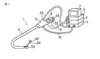
図1〜図8は第1の実施形態を示し、図1は内視鏡システムの全体構成を示し、図6は内視鏡の先端部の縦断側面図である。内視鏡システムは、図1に示すように、内視鏡1は先端湾曲部を持つ挿入部2と、操作部3とから構成されている。操作部3は外部に設置された光源装置4、カメラコントロールユニット(以下、CCUという)5にケーブル6で連結されている。CCU5はTVモニター7に接続されている。操作部3には先端湾曲部を操作するために操作ノブ8が設けられている。
【0008】
また、図6に示すように、内視鏡1には処置具挿通用のチャンネル56が設けられており、このチャンネル56内に、各種形態の処置具としての生検鉗子54を挿通して患部の処置を行うことができるようになっている。
【0009】
本実施形態では、電動で開閉、湾曲動作する生検鉗子54が使用されている。生検鉗子54の近位端は外部の処置具駆動制御装置(以下、駆動制御装置という)11に接続されている。駆動制御装置11は操作部3と接続コード12で接続されている。この接続コード12は操作部3に対して着脱自在になっており、電動処置具でない従来の処置具を使用する時は外した状態で使用できる。
【0010】
図1及び図6に示すように、内視鏡1の挿入部2の先端部53には生検鉗子54を挿通でき、手元側のチャンネル挿通孔55まで連通するチャンネル56と、鉗子起上台57が設けられている。鉗子起上台57は、ワイヤー58に連結され、ワイヤー58を矢印方向に引張ることで鉗子起上台57は起上し、生検鉗子54を起立できるようになっている。
【0011】
チャンネル56の終端部56a(すなわち、生検鉗子54が突出する直前の部分)の周壁には、受光素子59が設けられ、後述する受光信号をリード線60で手元側の操作部3へ伝送するようになっている。
【0012】
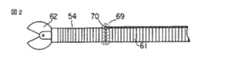
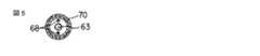
次に、内視鏡1と組み合わせ使用する生検鉗子54について説明する。図2〜図5及び図7に示すように、生検鉗子54には可撓管61が設けられている。この可撓管61の先端部には生体組織等を把持する把持部62が設けられている。一方、生検鉗子54の基端部は、図1に示す駆動制御装置11に接続されている。また、可撓管61内には把持部62の開閉用のワイヤー63が設けられている。
【0013】
図4に示すように、ワイヤー63の基端部にはラックアンドピニオン機構64が接続され、駆動制御装置11内でモータ65の回転機構によりワイヤー63を押し引きし、把持部62を開閉するようになっている。また、図3,図5に示すように、可撓管61内における先端部側には曲げ形状を記憶したSMAからなる例えばワイヤー状の一対の湾曲駆動部材66,67が可撓管61の軸心に対して線対称の位置に配設される。さらに湾曲駆動部材66,67には各々独立に通電加熱できるようにリード線68、68が接続されている。
【0014】
そして、各湾曲駆動部材66,67の通電加熱時の形状変化により、可撓管61の先端部を湾曲操作できるようになっている。なお、リード線68,68の基端部は、図1に示す外部の駆動制御装置11に接続されている。
【0015】
さらに、図2に示すように、生検鉗子54の湾曲部後方には発光手段69が設けられている。発光手段69は手元側から導びいた光ファイバーを可撓管61の外周上で周方向に丸めてある。この周方向に丸めた部分はコア材70のみからなる。
【0016】
このように構成された内視鏡システムは、内視鏡操作者が、内視鏡1を患者の消化管等に挿入する。そして生検等の処置が必要となった場合、駆動制御装置11に接続された生検鉗子54を、チャンネル挿通孔55に介してチャンネル56内に挿入する。生検鉗子54の湾曲部後方の発光手段69から発光しており、生検鉗子54がチャンネル56の終端部を通過した時点で受光素子59がこの光を感知する。この信号はリード線60により手元側の操作部3に送られ、接続ケーブル6を介して駆動制御装置11に送られる。
そして、図8に示すように、駆動制御装置11内の検出回路11a、処置具駆動制御部11bに送られる。そして、この信号伝達により、内視鏡1、操作ノブ8に設けた処置具操作スイッチとしての開閉用スイッチ22、湾曲操作スイッチ23は作動可能となる。
【0017】
このため、操作者は、生検鉗子54が目的処置部へ到達したら開閉用スイッチ22により、生検鉗子54、把持部62の開閉操作を行う。また、湾曲操作スイッチ23により、生検鉗子54、可撓管61の湾曲操作をして目的とする患部の処置を行なう。
【0018】
この実施形態によれば、複雑な内視鏡的処置を容易に行え、またチャンネル56から突出するまで生検鉗子54を作動できないため、生検鉗子54が誤ってチャンネル56、内視鏡1等を損傷することがない。
【0019】
なお、発光手段として、光ファイバーを用いたものを説明したが、これに限定されることなく、例えば、図9及び図10に示すようにLED71を生検鉗子54の湾曲部の後方に設けても良い。
【0020】
図11及び図12は第2の実施形態を示し、第1の実施形態と同一構成部分は同一番号を付して説明を省略する。第1の実施形態が処置具外表面の発光部からの光をチャンネル終端部に設けた受光素子で検出していたのに代え、本実施形態では、処置具外表面の濃淡を変化させている。すなわち、生検鉗子72の外表面は湾曲部73とその後方部74で色(濃淡)を変化させている。例えば湾曲部73は淡色、湾曲部73より後方部74は濃色としている。
【0021】
一方、内視鏡1の先端部53のチャンネル56の終端部には生検鉗子72の外表面の濃淡を読み取るCCD、CdS等より成る電荷蓄積素子75が設けられ、リード線60により検出信号を手元側へ送るようになっている。
【0022】
第1の実施形態と同じく、操作者は、処置が必要となった場合、駆動制御装置11に接続した生検鉗子72を内視鏡1のチャンネル56内に挿入する。そして生検鉗子72の湾曲部73の後方部74が電荷蓄積素子75上を通過し、濃淡が変化(淡→濃)すると、電荷蓄積素子75はこれを読み取り、リード線60により検出信号を手元側へ送信する。そして、この信号は接続ケーブル12を介して駆動制御装置11内の検出回路11a、処置具駆動制御部11bに送られる。そして、この信号伝達により内視鏡1の操作部3に設けた開閉用スイッチ22、湾曲操作スイッチ23は作動可能となり、操作者は目的患部を処置可能となる。したがって、第1の実施形態の効果に加え、処置具側の構成が簡単となる。
【0023】
図13及び図14は第3の実施形態を示し、第1,2の実施形態と同一構成部分は同一番号を付して説明を省略する。図13に示すように、生検鉗子54の手元側押し込み部には、生検鉗子54の把持部62がチャンネル56から完全に突出する押し込み量に相当する位置に、開閉用バーコード76が設けられている。同じく、生検鉗子54の湾曲駆動部材66,67がチャンネル56から完全に突出する押し込み量に相当する位置には、湾曲用バーコード77が設けられている。
【0024】
一方、内視鏡1の鉗子孔78の入口部には前記開閉用バーコード76、湾曲用バーコード77を読み取るためのバーコードリーダ79が設けられている。そして読み取った信号は接続ケーブル12を介して駆動制御装置11に送られ、操作部3に設けた開閉用スイッチ22、湾曲操作スイッチ23の駆動制御を行なえるようになっている。
【0025】
このように構成された内視鏡システムは、操作者が処置を必要とした場合、生検鉗子54を鉗子孔78に挿入する。そして、生検鉗子54の手元側の開閉用バーコード76がバーコードリーダ79を通過すると、これを読み取り、第1,2の実施形態と同じく接続ケーブル12を介して信号が駆動制御装置11に送られる。この時、生検鉗子54の把持部62はチャンネル56より突出している。そして操作部3に設けた開閉用スイッチ22が作動可能となり、術者は把持部62の開閉が行なえる。
【0026】
一方、生検鉗子54の手元側をさらに押し込むと、開閉用バーコード76がバーコードリーダ79を通過し、バーコードリーダ79がこれを読み取る。そして第1,2の実施形態と同じく接続ケーブル12を介して信号が駆動制御装置11に送られる。この時、生検鉗子54の湾曲駆動部材66,67は、チャンネル56より突出している。そして、操作部3に設けた湾曲操作スイッチ23が作動可能となり、術者は把持鉗子54の湾曲操作が行なえる。そして、術者は目的とする患部を処置可能となる。
【0027】
なお、第1〜第3の実施形態では、処置具として生検鉗子54について述べたが、これに限定されることなく、各種処置具が適用できる。また処置具の駆動機構(開閉、湾曲)としてSMA、モータ等を用いたものについて説明したが、これに限定されることなく、圧電アクチュエータ、ケモメカニカルアクチュエータ等、各種の駆動機構が利用できる。
【0028】
【発明の効果】
この発明によれば、複雑な内視鏡的処置を容易に行え、またチャンネルから処置具が突出するまで処置具が作動しないため、処置具が誤ってチャンネル、内視鏡等を損傷することがないという効果がある。
【図面の簡単な説明】
【図1】この発明の第1の実施形態を示す内視鏡システム全体の斜視図。
【図2】同実施形態の処置具の側面図。
【図3】同実施形態の処置具の縦断側面図。
【図4】同実施形態のラックアンドピニオン機構の側面図。
【図5】図3のA−A線に沿う断面図。
【図6】同実施形態の内視鏡の先端部の縦断側面図。
【図7】同実施形態の生検鉗子の斜視図。
【図8】同実施形態の作用を示すブロック図。
【図9】同実施形態の変形例を示す生検鉗子の側面図。
【図10】図9のB−B線に沿う断面図。
【図11】この発明の第2の実施形態を示す処置具の側面図。
【図12】同実施形態の内視鏡の先端部の縦断側面図。
【図13】この発明の第3の実施形態を示す操作部の斜視図。
【図14】同実施形態の操作部の縦断側面図。
【符号の説明】
1…内視鏡、2…挿入部、3…操作部、11…駆動制御装置(制御部)、54…生検鉗子(処置具)、56…チャンネル(鉗子挿入孔)、59…受光素子、69…発光素子[0001]
BACKGROUND OF THE INVENTION
The present invention relates to an endoscope system for observing and treating the inside of a body cavity.
[0002]
[Prior art]
Conventionally, when performing an endoscopic treatment, it has been carried out by a collaborative work between an operator holding and operating an endoscope and an assistant holding and operating a treatment instrument. In recent years, this endoscopic procedure is also an advanced and complicated procedure, and in the conventional method, considerable skill is required for an assistant to perform a procedure operation according to the will of the surgeon.
[0003]
Therefore, various types of motorized operation have been proposed for each endoscope or treatment tool for the purpose of improving operability, but there has been no proposal of a system that takes into account the operator's ease of operation.
[0004]
[Problems to be solved by the invention]
SUMMARY OF THE INVENTION An object of the present invention is to provide an endoscope system that can easily perform complicated endoscopic procedures and that does not accidentally damage channels, endoscopes, etc. by a treatment instrument.
[0005]
[Means for Solving the Problems]
In order to achieve the above object, the present invention provides an endoscope system including an endoscope having a forceps insertion hole, a treatment tool driven by an actuator means, and a control unit that controls the operation of the actuator means. , detecting means for detectingthat the treatment instrument to a portion of the forceps insertion hole is completely inserted is provided,the detecting means detects that the treatment instrument into the forceps insertion hole is fully inserted until it is characterized by comprising a safety mechanism that prohibits driving of the actuator means from the control unit by a signal ofsaid detecting means.
[0006]
DETAILED DESCRIPTION OF THE INVENTION
Embodiments of the present invention will be described below with reference to the drawings.
[0007]
FIGS. 1-8 shows 1st Embodiment, FIG. 1 shows the whole endoscope system structure, FIG. 6 is a vertical side view of the front-end | tip part of an endoscope. In the endoscope system, as shown in FIG. 1, the
[0008]
As shown in FIG. 6, the
[0009]
In this embodiment, a
[0010]
As shown in FIGS. 1 and 6, a
[0011]
A
[0012]
Next, the
[0013]
As shown in FIG. 4, a rack and
[0014]
And the bending | flexion operation of the front-end | tip part of the
[0015]
Further, as shown in FIG. 2, a light emitting means 69 is provided behind the curved portion of the
[0016]
In the endoscope system configured as described above, an endoscope operator inserts the
And as shown in FIG. 8, it sends to the detection circuit 11a in the
[0017]
For this reason, when the
[0018]
According to this embodiment, a complicated endoscopic treatment can be easily performed, and the
[0019]
In addition, although the thing using an optical fiber was demonstrated as a light emission means, it is not limited to this, For example, as shown in FIG.9 and FIG.10, even if LED71 is provided in the back of the curved part of the
[0020]
11 and 12 show a second embodiment, and the same components as those of the first embodiment are denoted by the same reference numerals and description thereof is omitted. Instead of detecting light from the light emitting portion on the outer surface of the treatment instrument with the light receiving element provided at the channel end portion in the first embodiment, in this embodiment, the shade on the outer surface of the treatment instrument is changed. . That is, the outer surface of the
[0021]
On the other hand, a
[0022]
Similar to the first embodiment, when treatment is required, the operator inserts the
[0023]
13 and 14 show a third embodiment, and the same components as those in the first and second embodiments are denoted by the same reference numerals and description thereof is omitted. As shown in FIG. 13, an opening /
[0024]
On the other hand, a
[0025]
The endoscope system configured as described above inserts the
[0026]
On the other hand, when the proximal side of the
[0027]
In the first to third embodiments, the
[0028]
【The invention's effect】
According to the present invention, a complicated endoscopic treatment can be easily performed, and the treatment tool does not operate until the treatment tool protrudes from the channel. Therefore, the treatment tool may damage the channel, the endoscope, etc. by mistake. There is no effect.
[Brief description of the drawings]
FIG. 1 is a perspective view of an entire endoscope system showing a first embodiment of the present invention.
FIG. 2 is a side view of the treatment tool of the embodiment.
FIG. 3 is a longitudinal side view of the treatment instrument of the embodiment.
FIG. 4 is a side view of the rack and pinion mechanism of the embodiment.
5 is a cross-sectional view taken along line AA in FIG.
FIG. 6 is a longitudinal side view of a distal end portion of the endoscope according to the embodiment.
FIG. 7 is a perspective view of the biopsy forceps according to the embodiment.
FIG. 8 is a block diagram showing the operation of the embodiment.
FIG. 9 is a side view of a biopsy forceps showing a modification of the embodiment.
10 is a cross-sectional view taken along line BB in FIG.
FIG. 11 is a side view of a treatment tool showing a second embodiment of the present invention.
FIG. 12 is a longitudinal side view of the distal end portion of the endoscope according to the embodiment.
FIG. 13 is a perspective view of an operation unit showing a third embodiment of the present invention.
FIG. 14 is a longitudinal side view of the operation unit of the embodiment.
[Explanation of symbols]
DESCRIPTION OF
Claims (4)
Translated fromJapanese前記鉗子挿入孔の一部に前記処置具が完全に挿通されたことを検出する検出手段を設け、この検出手段が、前記鉗子挿入孔に前記処置具が完全に挿通されたことを検出するまでは、該検出手段の信号によって前記制御部からアクチュエータ手段の駆動を禁止する安全機構を備えたことを特徴とする内視鏡システム。In an endoscope system including an endoscope having a forceps insertion hole, a treatment tool driven by an actuator means, and a control unit for controlling the operation of the actuator means,
Detecting means for detectingthat the treatment instrument to a portion of the forceps insertion hole is completely inserted is provided,until the detecting means detects that the treatment instrument into the forceps insertion hole is fully inserted the endoscope system characterized by comprising a safety mechanism that prohibits driving of the actuator means from the control unit by a signal ofsaid detecting means.
Priority Applications (1)
| Application Number | Priority Date | Filing Date | Title |
|---|---|---|---|
| JP07197797AJP3810177B2 (en) | 1997-03-25 | 1997-03-25 | Endoscope system |
Applications Claiming Priority (1)
| Application Number | Priority Date | Filing Date | Title |
|---|---|---|---|
| JP07197797AJP3810177B2 (en) | 1997-03-25 | 1997-03-25 | Endoscope system |
Publications (2)
| Publication Number | Publication Date |
|---|---|
| JPH10262900A JPH10262900A (en) | 1998-10-06 |
| JP3810177B2true JP3810177B2 (en) | 2006-08-16 |
Family
ID=13476042
Family Applications (1)
| Application Number | Title | Priority Date | Filing Date |
|---|---|---|---|
| JP07197797AExpired - Fee RelatedJP3810177B2 (en) | 1997-03-25 | 1997-03-25 | Endoscope system |
Country Status (1)
| Country | Link |
|---|---|
| JP (1) | JP3810177B2 (en) |
Cited By (2)
| Publication number | Priority date | Publication date | Assignee | Title |
|---|---|---|---|---|
| US9289111B2 (en) | 1999-03-12 | 2016-03-22 | Boston Scientific Scimed, Inc. | Controllable endoscopic sheath apparatus and related method of use |
| US9737196B2 (en) | 2008-07-18 | 2017-08-22 | Boston Scientific Scimed, Inc. | Endoscope with guide |
Families Citing this family (19)
| Publication number | Priority date | Publication date | Assignee | Title |
|---|---|---|---|---|
| JP2002078666A (en)* | 2000-09-05 | 2002-03-19 | Olympus Optical Co Ltd | Endoscope |
| JP4624572B2 (en)* | 2001-01-30 | 2011-02-02 | オリンパス株式会社 | Endoscope |
| JP2005237659A (en)* | 2004-02-26 | 2005-09-08 | Olympus Corp | Endoscopic treatment system |
| JP4723227B2 (en)* | 2004-11-15 | 2011-07-13 | Hoya株式会社 | Electronic endoscope system |
| JP4763307B2 (en)* | 2005-02-18 | 2011-08-31 | オリンパス株式会社 | Endoscopic treatment tool |
| JP4728075B2 (en)* | 2005-09-28 | 2011-07-20 | オリンパスメディカルシステムズ株式会社 | Endoscope system |
| JP4763420B2 (en)* | 2005-10-27 | 2011-08-31 | オリンパスメディカルシステムズ株式会社 | Endoscope operation assistance device |
| US7524284B2 (en)* | 2006-02-06 | 2009-04-28 | Olympus Medical Systems Corp. | Endoscopy system |
| JP5237608B2 (en)* | 2007-10-25 | 2013-07-17 | オリンパスメディカルシステムズ株式会社 | Medical equipment |
| JP2009254773A (en)* | 2008-03-28 | 2009-11-05 | Fujinon Corp | Ultrasonic diagnosis system and pump apparatus |
| JP5432473B2 (en)* | 2008-05-02 | 2014-03-05 | オリンパス株式会社 | Chemical solution administration device |
| CN102883649B (en)* | 2010-10-08 | 2016-02-24 | 奥林巴斯株式会社 | Endoscope |
| JP6053701B2 (en)* | 2013-10-22 | 2016-12-27 | オリンパス株式会社 | Manipulator system control method and manipulator system |
| WO2015060207A1 (en) | 2013-10-22 | 2015-04-30 | オリンパス株式会社 | Manipulator system control method and manipulator system |
| JP6238844B2 (en) | 2014-06-17 | 2017-11-29 | オリンパス株式会社 | Surgical manipulator operating device and surgical manipulator system |
| WO2016017222A1 (en)* | 2014-07-28 | 2016-02-04 | オリンパス株式会社 | Endoscope |
| US11213190B2 (en) | 2016-06-02 | 2022-01-04 | Gyrus Acmi, Inc. | Endoscope working channel protection |
| US20200154992A1 (en)* | 2018-11-16 | 2020-05-21 | Boston Scientific Scimed, Inc. | Button adapter for disposable ureteroscope |
| US12089817B2 (en)* | 2020-02-21 | 2024-09-17 | Canon U.S.A., Inc. | Controller for selectively controlling manual or robotic operation of endoscope probe |
- 1997
- 1997-03-25JPJP07197797Apatent/JP3810177B2/ennot_activeExpired - Fee Related
Cited By (6)
| Publication number | Priority date | Publication date | Assignee | Title |
|---|---|---|---|---|
| US9289111B2 (en) | 1999-03-12 | 2016-03-22 | Boston Scientific Scimed, Inc. | Controllable endoscopic sheath apparatus and related method of use |
| US9737196B2 (en) | 2008-07-18 | 2017-08-22 | Boston Scientific Scimed, Inc. | Endoscope with guide |
| US10178944B2 (en) | 2008-07-18 | 2019-01-15 | Boston Scientific Scimed, Inc. | Endoscope with guide |
| US10492666B2 (en) | 2008-07-18 | 2019-12-03 | Boston Scientific Scimed, Inc. | Endoscope with guide |
| US10881279B2 (en) | 2008-07-18 | 2021-01-05 | Boston Scientific Scimed, Inc. | Endoscope with guide |
| US12295551B2 (en) | 2008-07-18 | 2025-05-13 | Boston Scientific Scimed, Inc. | Endoscope with guide |
Also Published As
| Publication number | Publication date |
|---|---|
| JPH10262900A (en) | 1998-10-06 |
Similar Documents
| Publication | Publication Date | Title |
|---|---|---|
| JP3810177B2 (en) | Endoscope system | |
| JP3673157B2 (en) | Electric angle type electronic endoscope device | |
| JP4416990B2 (en) | System for operating a device in vivo | |
| JP4959579B2 (en) | Elongated medical material | |
| US7524284B2 (en) | Endoscopy system | |
| JP3854205B2 (en) | Endoscope device | |
| US8827922B2 (en) | Endoscope apparatus | |
| EP2340756B1 (en) | Medical instrument | |
| WO2006004053A1 (en) | Endoscope | |
| JP2009011809A (en) | Medical system | |
| JP2000000207A (en) | Treating tool inserting/drawing device for endoscope | |
| JP2005066139A (en) | Endoscopic high-frequency incision tool | |
| US20110288371A1 (en) | Endoscope device | |
| JP2000342516A (en) | Treatment endoscope and treatment tool | |
| JPH0260326B2 (en) | ||
| JPH04307050A (en) | Aspiration biopsy apparatus | |
| JP4323375B2 (en) | Endoscopic treatment tool and endoscope system | |
| JP5557237B2 (en) | Small diameter endoscope and small diameter endoscope set | |
| JPH07275197A (en) | Electronic endoscope apparatus for separating image pickup part | |
| JPH03139340A (en) | Treating implement for endoscope | |
| EP4245208A1 (en) | Endoscope system | |
| JP2966723B2 (en) | Electronic endoscope device that separates the imaging unit | |
| JPH07275196A (en) | Electronic endoscope apparatus for separating image pickup part | |
| JP2000014626A (en) | Endoscope | |
| WO2021176570A1 (en) | Endoscope system and method for operating endoscope |
Legal Events
| Date | Code | Title | Description |
|---|---|---|---|
| A621 | Written request for application examination | Free format text:JAPANESE INTERMEDIATE CODE: A621 Effective date:20040127 | |
| A977 | Report on retrieval | Free format text:JAPANESE INTERMEDIATE CODE: A971007 Effective date:20050915 | |
| A131 | Notification of reasons for refusal | Free format text:JAPANESE INTERMEDIATE CODE: A131 Effective date:20051004 | |
| A521 | Written amendment | Free format text:JAPANESE INTERMEDIATE CODE: A523 Effective date:20051130 | |
| A131 | Notification of reasons for refusal | Free format text:JAPANESE INTERMEDIATE CODE: A131 Effective date:20060207 | |
| A521 | Written amendment | Free format text:JAPANESE INTERMEDIATE CODE: A523 Effective date:20060405 | |
| TRDD | Decision of grant or rejection written | ||
| A01 | Written decision to grant a patent or to grant a registration (utility model) | Free format text:JAPANESE INTERMEDIATE CODE: A01 Effective date:20060516 | |
| A61 | First payment of annual fees (during grant procedure) | Free format text:JAPANESE INTERMEDIATE CODE: A61 Effective date:20060523 | |
| FPAY | Renewal fee payment (event date is renewal date of database) | Free format text:PAYMENT UNTIL: 20090602 Year of fee payment:3 | |
| FPAY | Renewal fee payment (event date is renewal date of database) | Free format text:PAYMENT UNTIL: 20100602 Year of fee payment:4 | |
| FPAY | Renewal fee payment (event date is renewal date of database) | Free format text:PAYMENT UNTIL: 20110602 Year of fee payment:5 | |
| FPAY | Renewal fee payment (event date is renewal date of database) | Free format text:PAYMENT UNTIL: 20120602 Year of fee payment:6 | |
| FPAY | Renewal fee payment (event date is renewal date of database) | Free format text:PAYMENT UNTIL: 20120602 Year of fee payment:6 | |
| FPAY | Renewal fee payment (event date is renewal date of database) | Free format text:PAYMENT UNTIL: 20130602 Year of fee payment:7 | |
| LAPS | Cancellation because of no payment of annual fees |